Abstract
The use of multi-joint arms in a high-spindle environment can solve complex problems, but the singularity problem of the manipulator related to the structure of the serial manipulator is prominent. Therefore, based on the general mathematical model of fruit spatial distribution in high-spindle apple orchards, this study proposes two harvesting system architecture schemes that can meet the constraints of fruit spatial distribution and reduce the singularity of harvesting robot operation, which are four-arm dual-module independent moving scheme (Scheme A) and four-arm single-module parallel moving scheme (Scheme B). Based on the link-joint method, the analytical expression of the singular configuration of the redundant degree of freedom arm group system under the two schemes is obtained. Then, the inverse kinematics solution method of the redundant arm group and the singularity avoidance picking trajectory planning strategy are proposed to realize the judgment and solution of the singular configuration in the complex working environment of the high-spindle. The singularity rate of Scheme A in the simulation environment is 17.098%, and the singularity rate of Scheme B is only 6.74%. In the field experiment, the singularity rate of Scheme A is 26.18%, while the singularity rate of Scheme B is 13.22%. The success rate of Schemes A and B are 80.49% and 72.33%, respectively. Through experimental comparison and analysis, Scheme B is more prominent in solving singular problems but still needs to improve the success rate in future research. This paper can provide a reference for solving the singular problems in the complex working environment of high spindles.
1. Introduction
Global production of apples is expected to increase to 83.1 million tons by 2024 [1]. As the world’s largest producer and consumer of apples, China’s apple planting area and production account for more than 40% of the world’s total and show an increasing trend year by year [2,3]. As a labor-intensive industry, apple harvesting accounts for about 30% of the total production process and 35% of the total production cost, but it is still mainly manual harvesting [4]. With the increasing hollowing out of rural areas and the aging of fruit farmers, the shortage of human resources has become the biggest problem in the production process, and high-speed mechanized operation has become an urgent need [5].
In response to the urgent needs of the apple harvesting industry, countries around the world are accelerating the development of corresponding machinery. At present, harvesting robots have become a research hotspot, and with high speed and high efficiency as the core, it is gradually developing in the direction of large-scale, multi-arm, and unmanned [6]. Among them, the rational use of harvesting robots with multiple manipulators working at the same time can significantly improve the harvesting efficiency of robots [7,8,9,10,11], which has become the main trend in the development of harvesting robots. At the same time, with the increasing demand for apple production year by year and the continuous improvement in agronomic technology, apple planting has changed from traditional unstructured orchard structure to dwarf and dense orchard, such as Tall-Spindle Structure, V-Trellis Structure, Vertical Fruiting Wall [12,13]. Compared with the traditional unstructured apple orchard, the dwarfed apple trees have early fruiting, are suitable for close planting, and have a high yield. At the same time, its canopy is small, and the fruit distribution is relatively concentrated, which provides the possibility for mechanized harvesting operations [14]. However, the actual management and maintenance of dwarf and close planting apple orchards in China cannot meet the agronomic technical standards, and the individual differences in fruit, canopy, and inter-row environment still exist. The complex internal environment of the apple tree canopy and the wide and uneven distribution of fruits lead to many problems in robot harvesting in this environment.
For the spatially distributed fruits and complex canopy, the rational design of the robot’s structural scheme has become the primary prerequisite for high-speed harvesting performance and successful harvesting. In the aspect of mechanical arm selection, a multi-joint arm can realize the dexterous operation similar to a human arm [15,16]. Because of its advantages of precision, flexibility, and good flexibility, it has been applied from the industrial field to the agricultural field and has become a research hotspot of agricultural harvesting robot selection and harvesting technology. Marsela et al. proposed a pepper harvesting robot system for a structured greenhouse environment [17]. This system adopts a 6-DOF flexible multi-joint manipulator, which can effectively solve the influence of branch and leaf occlusion on the accessibility of harvesting robots in complex working environments. Yoshida et al. designed a dual-arm fruit harvesting robot for the joint V-shaped trellis [18]. The 6-DOF manipulator can achieve selective fruit harvesting by bypassing obstacles through motion planning. Aiming at the problem of automatic harvesting of eggplant in an unstructured environment, Delia SepúLveda et al. used a flexible 6-DOF manipulator and proposed a decision strategy of a dual-arm robot system, which improved the success rate of harvesting [19]. In the scheme design of the harvesting system, the existing research puts forward the harvesting requirements of full coverage of fruit growth area. Through the simulation analysis of the spatial size relationship between the robot and the canopy or fruit growth area of fruit trees, the arm size that can meet the requirements of coverage harvesting is obtained [20,21], and the robot configuration scheme and key components that can meet the conditions of full coverage harvesting are optimized [22,23,24,25,26]. Some studies have analyzed the operable space or accessibility of robots [27,28] and used robot kinematics modeling and trajectory planning to maximize the robot harvest rate [29,30,31].
However, the use of multi-joint arms in a high-spindle environment can solve complex problems, but the singularity problem of the manipulator related to the structure of the serial manipulator is prominent. The singular configuration is a special structural configuration inside the mechanism. When the manipulator is in a singular configuration, it will cause the manipulator’s operable degree of freedom to be missing, the flexibility to be reduced, and the speed to change abruptly. As a result, the manipulator system loses its precise control of its velocity matrix, which makes the stability of the multi-joint manipulator worse and even stops acting [32]. Due to the decrease in the degree of freedom and flexibility, there are holes in the operable space of the robot, such that some fruits within the range of the manipulator’s arm can be theoretically reached but cannot be actually reached, which reduces the net rate and the success rate of harvesting.
The size of the robot’s singular workspace is closely related to the robot architecture scheme, which directly affects the success rate and efficiency of the operation. However, most of the existing design schemes are based on the idealization of the working environment. There are few studies on the analysis of the influence of singularity on the working performance of the manipulator in complex environments, and there is insufficient discussion on the coupling relationship between the singularity of the manipulator and the singularity space of the robot. Therefore, indicators such as harvesting success rate and efficiency are more idealized and do not conform to the actual situation in the field [33,34,35].
Therefore, this paper aims to address the problem of the singularity of the multi-joint arm in the high-spindle environment, which leads to the interruption of the operation and the reduction in the robot’s operable space. By generalizing the spatial distribution characteristics of the fruit in the high-spindle apple orchard, two harvesting system architecture schemes that can meet the spatial distribution constraints of the fruit and reduce the singularity of the harvesting robot’s operation are proposed, which are the four-arm dual-module independent moving scheme and the four-arm single-module parallel moving scheme. Then, according to the operation scheme of the harvesting robot, the inverse kinematics solution method of the redundant degree of freedom arm group system and the picking trajectory planning strategy for singularity avoidance is proposed. Finally, the singularity judgment and solution in the complex working environment of the high-spindle are finally realized.
This paper is structured as follows: The singularity problem faced by the harvesting robot in the high-spindle environment is analyzed in Section 2.1. In Section 2.2, two design schemes of harvesting robots under complex constraints of high-spindle are proposed. The singular configuration of the harvesting robot is analyzed, and the singularity avoidance planning strategy is proposed in Section 2.3. In Section 3.1 and Section 3.2, the singularity rate analysis and harvesting success rate analysis of the two design schemes are carried out, respectively. Finally, the research is summarized, and the prospect of future research is presented in Section 4.
2. Materials and Methods
2.1. The Singularity Problem of Harvesting Robot in High-Spindle Environment
2.1.1. Complexity of High-Spindle Cultivation Mode
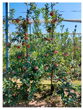
The high-spindle cultivation mode has the advantages of high yield, good fruit quality, convenient management, and suitable mechanized operation, and it has become the main form of dwarf and dense planting orchard promotion in China. Take the high-spindle apple orchard in Sweet Orchard in Suqian City, Jiangsu Province, as an example. The planting row spacing is 350 cm, the passable width is 160 cm, the tree height is between 350 and 400 cm, the fruit height interval is between 30 and 300 cm, the average crown width of fruit trees is between 100 and 150 cm, and the crown depth can reach 80~110 cm. There is a trapezoidal ridge surface with a height of 20–30 cm under the fruit tree. The overall structural characteristics are shown in Figure 1.
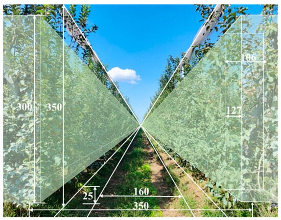
Figure 1.
The structural characteristics and tree shape characteristics of high-spindle apple trees in Sweet Orchard.
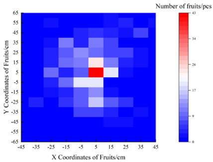
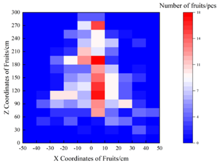
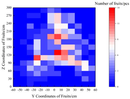
According to the investigation results, the cultivation mode of high-spindle apple trees in Sweet Orchard has tended to be standardized, but the management level is low. The main performance is that there is a gap between the pruning, flower thinning, fruit thinning, and other links of fruit trees and the relevant technical standards, resulting in obvious differences and complexity in different tree specifications and fruit distribution. (Table 1).

Table 1.
The challenges and specific performance of harvesting robots in high-spindle apple orchards.
The projection distribution results of fruits on xy, xz, and yz planes in Table 1 showed that the fruits in Sweet Orchard were approximately symmetrically distributed in the depth direction and the width direction with the canopy center as the symmetrical axis, and the distribution intervals were [−40, 40] cm and [−60, 80] cm, respectively. The height direction distribution range can reach 50~300 cm, and the fruit is concentrated between 50 and 200 cm. Therefore, the fruit distribution of a high-spindle apple orchard is characterized by uneven height and wide coverage.
At the same time, due to the limitation of the orchard management level, there are obvious differences in canopy specifications between different trees, and the canopy occlusion between adjacent trees is serious. The crown depth of fruit trees is characterized by a narrow upper and wide lower, and the overall depth is obviously uneven. This large-scale distribution of fruits and highly unstructured operating conditions not only have a greater demand for the robot’s operating space but also pose a challenge to the robot’s adaptability and flexible action in a differentiated environment.
2.1.2. The Singularity Problem Under the Influence of Multiple Factors
The singular configuration is a special configuration of the multi-joint manipulator, which is affected by the structure of the manipulator and the task. When the rotation of some joints is in the limit position, or the mechanism enters the dead point due to the interference of the connecting rod during the movement, the manipulator enters the singular state. The multi-joint arm used in the existing agricultural scene is mostly an industrial cooperative arm. In the actual operation process, the maximum arm span of the manipulator is often greater than the linear distance to the fruit. However, when the picking action is performed in a certain position, the degree of freedom of the joint is lost or even triggers a sudden stop, resulting in unreachable actual operation. At this time, the manipulator is in a singular configuration state, and it usually needs manual intervention to start working again, which seriously affects the picking continuity and operation efficiency.
Affected by the management level of high-spindle apple orchards, the complexity and uncertainty of robot-picking tasks have multiplied. Therefore, the multi-joint arm makes it easy to enter the singular state in the face of the operation task in this environment. The main reasons for the singularity include the following:
- (1)
- In the high-spindle operating environment, the robot is required to meet the requirements of large-scale and non-uniform distribution of fruits and to adapt to the highly unstructured canopy. Therefore, the robot’s operable space formed by the canopy-body manipulator does not match the environmental constraint space. When the manipulator is located at the edge of the workspace, it will enter the boundary singularity due to the joint reaching the limit state, as shown in Figure 2a; when picking the proximal end, the joints are more likely to pin each other down, thus entering the internal singularity, as shown in Figure 2b;
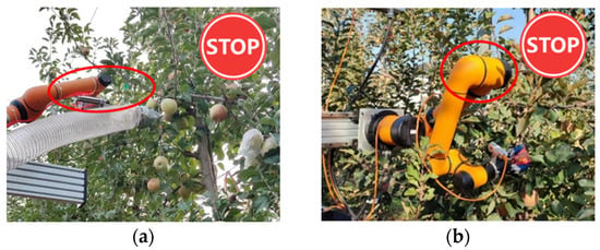 Figure 2. The trigger reason and actual influence of the singularity problem of the manipulator in the high-spindle cultivation mode. (a) Boundary singularity caused by a narrow upper canopy layer. (b) Elbow singularity caused by the opening of the lower canopy.
 - (2)
- In order to ensure successful harvesting, the end-effector needs to approach and pick the fruit in a specific posture. Therefore, when the target fruit is located in the interlaced area of the branches of the fruit tree or the outer area of the large canopy at the bottom, the changeable posture of the end may force some joints of the manipulator to enter the singularity, increasing the risk of singularity in the joint space, thus reducing the effective working space of the robot.
- (3)
- The existing industrial cooperative arm mostly uses the built-in controller for IK solution and path planning. Therefore, the singularity problem of the manipulator is not paid attention to when performing the harvesting action of the target point, which leads to the singularity of the manipulator during the movement from the initial picking point to the target picking point.
The successful harvesting in complex agricultural scenes does not depend entirely on the manipulator itself. The robot configuration scheme with a multi-joint arm determines the interaction mode between the manipulator and the working environment, which in turn affects the singular spatial distribution of the manipulator. In view of the above trigger reasons, based on the analysis of high-spindle scene constraints, it is important to explore the mapping relationship between robot operation requirements and its own singularity and to propose configuration schemes and motion planning methods that can reduce the singularity of robots.
2.2. Design of Harvesting Robot Under Complex Constraints of High-Spindle
2.2.1. Establishment of Fruit Spatial Distribution Model
The fruit distribution of high-spindle apple orchards is characterized by non-uniformity and significant differences among different trees, which aggravates the complexity of picking tasks. Therefore, the establishment of mathematical models to express the spatial distribution characteristics of high-spindle apple orchards has become the primary prerequisite for clarifying the operating space of harvesting robots.
A random sampling method was used to randomly select 50 5-year-old fruit trees in the orchard. The local base coordinate system was established at the intersection of the apple tree trunk and the ridge surface, and the three-dimensional coordinates of the fruit center point were measured. The x (Depth), y (Width), and z (Height) coordinates of the fruit in the collected data were extracted. After the data were standardized, the distribution test and nonlinear curve fitting were performed, respectively. The results showed that the z coordinate satisfied the normal distribution . Here, the mean value of the z coordinate was 149.7239 cm, the standard deviation was 65.61215, and the 95% confidence interval of the mean value was [143.5121, 155.9357] cm (Figure 3a). The x and y coordinates do not satisfy the normal distribution and show multi-peak characteristics, and there are multiple aggregation areas (Figure 3b).
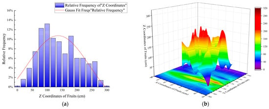
Figure 3.
High-spindle apple three-dimensional coordinate nonlinear curve fitting results and 3D heat map. (a) z coordinate nonlinear curve fitting results of fruits. (b) Three-dimensional coordinate 3D heat map and xy surface projection map of fruits.
The Gaussian Mixed Model can solve the problem of the data containing multiple different distributions and can be used to establish a mathematical model under the multi-peak distribution characteristics of the x and y coordinates of the high-spindle fruit. From a geometric point of view, GMM is defined as follows [36]:
Here, is the weight, and = 1, are the mean and variance of the i th Gaussian mixture distribution.
In this paper, the Bayesian information criterion (BIC) is used to determine the optimal number of Gaussian distributions in the data set. Based on the GMM clustering idea, the expectation maximization (EM) algorithm is used to solve the posterior probability distribution of the hidden variable zi corresponding to the x and y coordinates of the fruit after the t-cycle as follows:
Here, and are the normal distribution probability density functions of fruit x and y coordinates, respectively.
The weight , mean , and covariance corresponding to the x and y coordinates of the fruit in the t + 1th cycle are further solved until convergence. The fitting convergence results are shown in Figure 4. The mean value of the final x coordinate converges to 1.03765 cm, and the standard deviation converges to 15.85759 cm. The mean value of the y coordinate converges to 6.058 cm, and the standard deviation converges to 24.43194 cm.
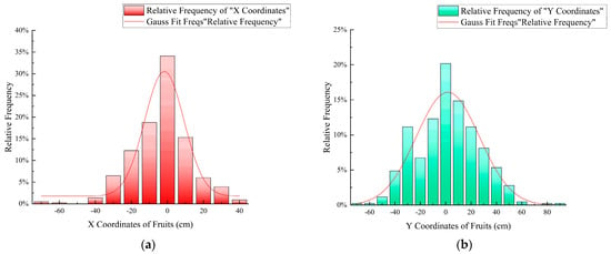
Figure 4.
Gaussian mixture model for x, y coordinate of fruit. (a) x coordinate fitting results. (b) y coordinate fitting results.
Considering the extreme situation of fruit growth in the orchard, according to the 2σ principle in statistics, the growth space U of high-spindle apple is described as follows:
Here, the x, y, and z coordinates of the fruit are 95.44% likely to fall into the above interval.
2.2.2. Four-Arm Synchronous Harvesting System Architecture Scheme
Under the high-spindle cultivation mode, the fruit trees are symmetrically distributed on both sides of the tree row, and the parameters such as plant spacing and row spacing are relatively uniform. Therefore, based on the standardized structural parameters of the high-spindle orchard and the mathematical model of fruit spatial distribution (Section 2.2.1), two kinds of system architecture schemes of four-arm synchronous harvesting are proposed, as shown in Figure 5. It is composed of an autonomous navigation chassis system (1-1, 1-2), a four-arm two-dimensional moving harvesting system (2-1, 2-2, 2-3, 2-4, 2-5), a fruit recovery system (3-1, 3-2) and a control system (4). In Figure 5a, 6-DOF cooperative arms are symmetrically arranged on both sides of the two-level bidirectional moving module. In Figure 5b, four 6-DOF cooperative arms are arranged in pairs on both sides of a horizontal two-way moving module. In both configuration schemes, the harvest of fruits inside the canopy is completed through the horizontal two-way moving module sliding table feed and the cooperative division of labor between the vertical ipsilateral two-arm system.
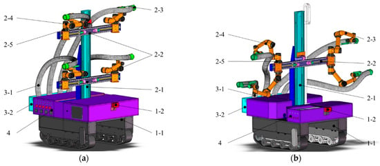
Figure 5.
Four-arm apple harvesting robot four-arm synchronous harvesting system architecture scheme. (a) Bilateral four-arm dual-module independent moving scheme. (b) Double-sided four-arm single-module parallel moving scheme. 1-1 and 1-2 represent the tracked chassis and multi-line lidar in the autonomous navigation chassis system, respectively. 2-1, 2-2, 2-3, 2-4, and 2-5 represent the vertical large-scale bidirectional active moving module, horizontal bidirectional moving module, swallowing end effector, 6-DOF cooperative arm and depth camera in the four-arm two-dimensional moving harvesting system, respectively. 3-1 and 3-2 represent the recovery hose and fruit box in the fruit recovery system, respectively. 4 represents the control system.
In terms of theory, the reachability of the robot’s hand-arm depends on the depth distance of the fruit in the canopy and the extension limit of the hand-arm. Therefore, the longer the arm’s length, the easier it is to approach the fruit near the center of the canopy. However, the hand-arm growth will directly increase the probability of collision with the crown element and its own singularity, reducing the flexibility of the manipulator [28]. To this end, we define a composite system composed of a swallowing end effector, a 6-DOF cooperative arm, and a horizontal bidirectional moving module sliding table as an arm group system, as shown in Figure 6. The arm group system can realize the global workspace expansion of the robot through the lateral movement of the horizontal bidirectional moving module to reduce the collision and singular configuration problems caused by the arm length when the installation position of the manipulator is fixed.
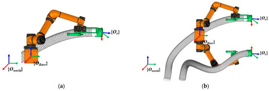
Figure 6.
Four-arm apple harvesting robot arm group system diagram. (a) Bilateral four-arm dual-module independent moving scheme arm group system. (b) Bilateral four-arm single-module parallel moving scheme arm group system.
2.2.3. Four-Arm Layout and Workspace Allocation
In order to meet the basic needs of the harvesting robot working space to cover the fruit growth space, the robot adopts the straight walking method and the walking–stop–harvesting operation method between the tree rows. With the trunk center as the symmetry axis, the robot walks straight along the tree row while completing the fruit harvesting in the red dotted line area inside the tree row. After the whole row harvesting is completed, the robot turns at the head of the row and starts the next line of operation.
Due to the non-uniform distribution of apples in the height direction under the high-spindle cultivation mode, the four-arm workspace should be divided according to the task volume. For a bilateral four-arm dual-module independent moving scheme (Hereinafter referred to as Scheme A), the operation area of the upper side arm group system is defined as Wu, and the operation area of the lower side arm group system is Wd (Figure 7a). The movement amount of the upper side arm group system in the z-axis direction is ha1, and the movement amount of the lower side arm group system in the z-axis direction is ha2. The two operation areas meet the following conditions:
Here, n is the number of fruits obtained by the visual system in Wu, is the Euclidean distance from the fruit in the {Oworld} coordinate system to the origin of the corresponding arm group system base, m is the number of fruits obtained by the visual system in W.
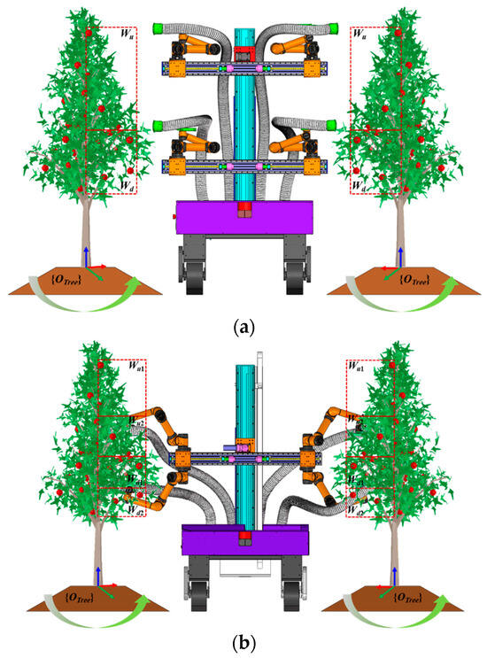
Figure 7.
Four-arm apple harvesting robot workspace diagram. (a) Scheme A. (b) Scheme B.
For the double-sided four-arm single-module parallel moving scheme (Hereinafter referred to as Scheme B), because the upper and lower arms have a parallel relationship in the y-axis direction, Wu and Wd are the common working areas of the upper and lower arm group system. At this time, Wu and Wd are equally divided into sub-operation areas Wu1, Wu2, Wd1, and Wd2 (Figure 7b) according to the principle of the same tasks. At this time, the movement of the arm group system in the z-axis direction is ha, and the sub-operation area meets the following conditions:
Here, n1 is the number of fruits obtained by the visual system in Wu1, n2 is the number of fruits obtained by the visual system in Wu2, and n3 is the number of fruits obtained by the visual system in Wd1.
The working space and working process of the harvesting robot are shown in Figure 8. Every time the chassis stops, the working space on one side of the harvesting robot is represented by the red dotted line area Wi, and its expression is as follows:
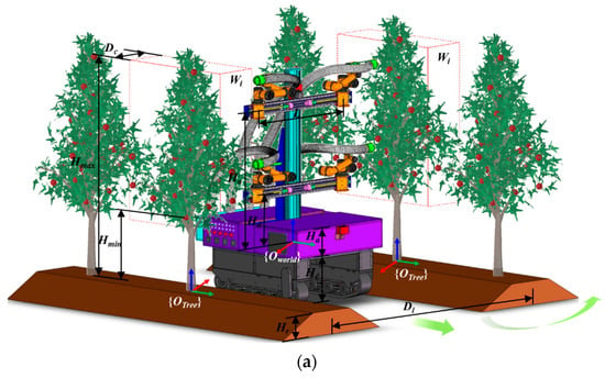
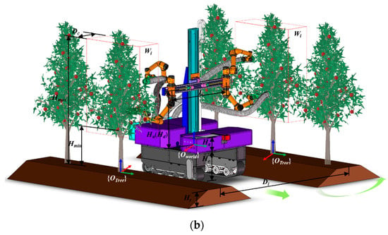
Figure 8.
Four-arm apple harvesting robot operation process diagram. (a) Scheme A. (b) Scheme B.
The schematic diagram of the working process of the four-arm apple harvesting robot. In order to meet the reachable demand of the target fruit in the Wi area, the working radius of the arm is set to Rm, and the relationship should be satisfied as follows:
Here, Hr is the height of the ridge surface, Ha is the height of the control box, Hc is the height of the chassis, and Hd is the distance between the lower arm group and the chassis. Rm is the maximum working radius of the hand-arm, Hmin is the minimum growth height of the fruit in the robot workspace, and Hmax is the maximum growth height of the fruit in the robot workspace. Dl is the planting spacing, and L is the maximum installation spacing of the horizontal ipsilateral arm group system.
Combined with the working environment parameters of the high-spindle apple orchard, the selection results, and the above relationship derivation, the key parameters of the four-arm harvesting robot are obtained, as shown in Table 2.

Table 2.
Key parameters of four-arm apple harvesting robot.
2.3. Singularity Analysis and Non-Singularity Planning of Harvesting Robot
2.3.1. Singular Configuration Description of Harvesting Robot
For the two system architecture schemes proposed in this research, the arm groups are parallel operation relationships; thus, there is no kinematic coupling constraint between the end-effectors. Therefore, the arm group system still belongs to the series manipulator group, and the singularity analysis of the single arm group system can be carried out according to the independent system.
In this paper, a simple method based on link-joint is used to construct the Jacobian matrix of the arm group system to avoid the complex matrix operation of the traditional analytical method [37,38] and judge the singularity condition of the arm group system according to the Jacobian matrix.
Firstly, the forward kinematics model of the arm group system needs to be established. For Scheme A, the arm group system includes two moving pairs and six rotating pairs at the base part, and its degree of freedom is 8. The swallowing end-effector is directly fixed on the end flange of the manipulator; thus, it can be regarded as a connecting rod with a length of d7. There is no relative rotation relationship between the sixth joint and the end of the manipulator. Aiming at Scheme B proposed in this study, the arm group system includes two moving pairs at the base part and six revolute pairs provided by the upper and lower arms, respectively, with a degree of freedom of 14.
The standard D-H parameter method is used to establish the connecting rod coordinate system of the arm group system of the two schemes, as shown in Figure 9. The corresponding D-H parameters of the 6-DOF cooperative arm are shown in Table 3. Here, θi is joint angle, di is link offset, ai is link length, and αi is link twist.
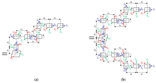
Figure 9.
Arm group system connecting rod coordinate system. (a) Scheme A. (b) Scheme B.

Table 3.
D-H parameters of the 6-DOF cooperative arm.
For Scheme A, in the {Oworld} coordinate system, the base of the arm group moves in the Y0 and Z0 directions. Assuming that the distance of the base in the Y0 direction is da and the distance in the Z0 direction is ha, then the pose transformation matrix between the arm group base and the world coordinate system is as follows:
The pose transformation relationship between joint 6 of the 6-DOF manipulator and the base of the arm group can be expressed by the following homogeneous transformation matrix of the adjacent connecting rod:
Here, is , is , is , is .
In the {Otool} coordinate system, the end-effector offsets d7 in the Z6 direction. Thus, the pose transformation matrix of the swallowing end-effector and the sixth joint of the manipulator is as follows:
The forward kinematics equation of the arm group system can be expressed as follows:
Here, is the x-axis unit vector of the {Otool} coordinate system, is the y-axis unit vector of the {Otool} coordinate system, is the z-axis unit vector of the {Otool} coordinate system, is the end position vector.
For the rotating joint i in the arm group system, the Jacobian matrix can be directly constructed by using the direction vector of each joint axis and the position vector of the connecting rod. The generalized Jacobian matrix under the composite system is composed of the manipulator, and the module is a 6 × 8 matrix. The expression is as follows:
Here, is the Jacobian matrix J(θi) of the rotary joint, is the Jacobian matrix J(da,ha) of the base translation pair. and are the linear velocity part and the angular velocity part of the Jacobian matrix J(θi) of the rotary joint, respectively, is the axis direction vector of the joint i−1, is the position vector of the end reference point, and is the position vector of the manipulator link i−1.
For the base moving pair in the arm group system, because it only affects the movement in the Y0 and Z0 directions in the coordinate system {Oworld}, the following is established:
For Scheme B, the generalized Jacobian matrix under the composite system of the manipulator and the module is a 6 × 14 matrix, and the block expression is as follows:
Here, is the Jacobian matrix J(θi) of the upper arm rotary joint, is the Jacobian matrix J(θi) of the lower arm rotation joint, and is the Jacobian matrix J(da,ha) of the base translation pair.
For the base moving pair of the arm group system in this scheme, it only affects the movement in the Y0 and Z0 directions in the {Oworld} coordinate system. Therefore, the following is established:
2.3.2. Non-Singular Inverse Kinematics Solution
In the two schemes proposed in this paper, because the arm group system contains redundant degrees of freedom, the IK solution for singular configuration avoidance in the robot workspace becomes a difficult problem [39]. Therefore, the decomposition method is used to describe the redundancy of the degree of freedom of the arm group system, and the IK solution method for the singularity avoidance of the redundant degree of freedom of the arm group system is proposed by considering the singularity constraint.
In Scheme A, the redundant degrees of freedom of the arm group can be decomposed into two translational degrees of freedom and six rotational degrees of freedom (Figure 10a). Since the axes of the adjacent joints 2, 3, and 4 are parallel to each other and satisfy the Pieper criterion, the IK solution task of the desired end pose can be divided into the following two steps:
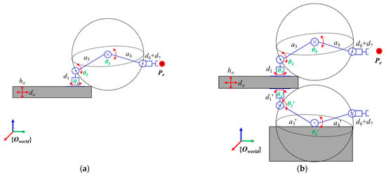
Figure 10.
The results of the arm group system are simplified by the decomposition method. (a) Scheme A. (b) Scheme B.
- (1)
- Position solution: Firstly, the translation variable ha is determined according to the operation space allocation result of the harvesting robot. Then, by converting the expected position of the end-effector to the position of joint 3 of the manipulator, the translation variable da and the joint rotation θ1, θ2, and θ3 can be solved.
- (2)
- Attitude solution: After obtaining the values of θ1, θ2, and θ3, the rotation amount of the last three joints, θ4, θ5, and θ6, is solved by using the rotation matrix and the end attitude matrix .
According to Figure 10a, the position vector of joint 3 in the {Oworld} coordinate system is obtained from the expected position Pe of the end-effector as follows:
Let the position of joint 1 in the {Oworld} coordinate system be P1 = , then the position vector of joint 3 pointing to joint 1 in the {OBase} coordinate system is as follows:
Here, is the transformation matrix from {Oworld} coordinate system to {OBase} coordinate system.
By projecting to the x1z1 plane of joint 1 and eliminating the vector in the y1 direction, we can obtain the following:
Here, is the element of row i and column j in the matrix .
When the multiple sets of IK of the target pose do not satisfy the non-singularity condition, that is, to avoid the singular IK solution results of the redundant arm group, the non-singular condition is as follows:
Here, is the manipulability, and is a 6 × 6 manipulability matrix.
In Scheme B, the redundant degrees of freedom of the arm group can be decomposed into two translational degrees of freedom, six rotational degrees of freedom of the upper arm, and 6-DOF of the lower arm (Figure 10b).
For the expected position of the end-effector, it is first necessary to determine the operating area according to the ye. When , it is located within the operating range of the upper arm group system. On the contrary, it is located in the working range of the lower arm group system. The solution method of the arm group translation da and the joint rotation θi (i = 1, …, 6) is the same as that of Scheme A.
The non-singular condition is as follows:
Here, is the manipulability, and is a 6 × 6 manipulability matrix.
2.3.3. Picking Trajectory Planning Strategy for Singularity Avoidance
In Section 2.3.2, the IK problem of the redundant degree-of-freedom arm group system is solved by the decomposition method. The non-singular IK solution can be directly judged and screened by the singular condition to achieve the purpose of singularity avoidance in the joint space. However, avoiding a singular configuration also requires considering the end trajectory. Since the industrial cooperative arm mostly uses the built-in controller to carry out path planning directly, the path planning algorithm only considers the optimal path and does not pay attention to the singularity problem. Therefore, the joint velocity will still change abruptly or fluctuate violently during the movement of the manipulator. At this time, the trajectory of the end effector will enter or close to the singular region.
Aiming at the singularity problem in the harvesting trajectory, this paper proposes a singularity avoidance planning strategy combining Cartesian space planning and joint space planning and combines the built-in controller of the 6-DOF cooperative arm to complete the singularity avoidance control. The planning and control process is shown in Figure 11.
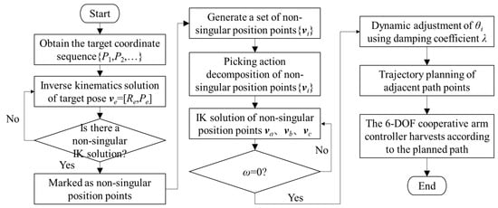
Figure 11.
Attitude control flow chart of the harvesting robot based on model predictive control.
Firstly, the IK solution of the arm group system needs to be calculated according to the target pose corresponding to the fruit coordinates. When the target pose does not have a non-singular IK solution, the point coordinates are eliminated, and a non-singular pose set {vi} is generated. Then, the picking action of each target point in {vi} is decomposed into three steps: preview, swallow, and avoidance (Figure 12). The picking path can be divided into the following three path points (va, vb, and vc):

Figure 12.
Picking action decomposition diagram. (a) Preview. (b) Swallow. (c) Avoidance.
Here, is the amount of feed, and is the safety value of avoidance.
In each path point, when the target velocity of the end-effector is x, the joint velocity q can be obtained by using the generalized Jacobian matrix J as follows:
Here, λ is the damping coefficient, and I is the unit matrix.
Here, is the damping coefficient of foundation, and is the strange suppression gain.
At time , when the starting joint angle of the manipulator is θ0 and the end joint angle is θT, for each adjacent path point, the quintic polynomial is used for interpolation as follows:
The constraint condition is as follows:
3. Results and Discussion
3.1. Simulation Experiment
In order to verify whether the design scheme proposed in this paper is helpful in solving the singularity problem in the complex environment of high-spindle, the simulation test is carried out in MATLAB R2019 b software.
3.1.1. Singularity Distribution
Based on the description of the singular configuration in Section 2.3.1, the singular space of the arm group under the two design schemes is solved by using the MATLAB Robotics Toolbox. The singular rate is used to represent the proportion of singular space, and the singular rate is defined as follows:
Here, ns is the number of singular points in the operable space, and nc is the number of sampling points in the operable space.
For Scheme A, the upper side arm group is taken as an example to calculate its singular space. The scheme sets the upper arm group movement constraint f1(d1, h1) with d1 being 80 cm, h1 being 120 cm, and the arm group being located at the outermost position of the horizontal two-way moving module. The projection of the singular space Sf1 on the xy, xz, and yz planes is in Figure 13 when the number of sampling points N = 50,000 and the generalized Jacobian matrix of the arm group satisfies the singularity determination condition.

Figure 13.
The singular space distribution of the arm group in Scheme A. (a) xy plane projection. (b) xz plane projection. (c) yz plane projection.
The red spherical region is the singular space of the arm group, and the red scatter is the singular point in the operable space. The coordinates of singular points are extracted, and 2% extreme values are removed. The relative frequency curves of the number of singular points with the change in x, y, and z values are drawn, as shown in Figure 14. The number of singular points is 8549, and the singularity rate is 17.098%.

Figure 14.
The relative frequency curve of singular points in Scheme A. (a) Variation of relative frequency distribution of with x values. (b) Variation of relative frequency of singularities with y values. (c) Variation of relative frequency distribution of with z values.
The change in the relative frequency of the singular point distribution of the arm group with the values of x, y, and z is an approximate even function of the values of x, y, and z. In the cylindrical region composed of x ∈ [−28.2, 36.2] cm, y ∈ [35.7, 129.7] cm, z ∈ [−20.85, 62.85] cm, it is a singular high-incidence area, which is consistent with the trend reflected in Figure 13. For Scheme B, Figure 15a–c is the projection of the singular space of the arm group when the number of sampling points is N = 50,000, d1 = 80 cm, h1 = 120 cm. Among them, the red spherical region is the singular space Sup of the upper arm, and the blue spherical region is the singular space Sdown of the lower arm. The union of the two is the singular space Sf2 of the right arm group. The total number of singular points is 3370, and the singularity rate is 6.74%.

Figure 15.
The singular space distribution of the arm group in Scheme B. (a) xy plane projection. (b) xz plane projection. (c) yz plane projection.
The coordinates of singular points are extracted, and 2% extreme values are removed. The relative frequency curves of the number of singular points with x, y, and z values are drawn as shown in Figure 16a–c. It can be seen from the above results that the relative frequency of the singular point distribution of the arm group is also an approximate even function of x, y, and z values, and the columnar region composed of x ∈ [−36.2, 19.0] cm, y ∈ [33.7, 127.7] cm, z ∈ [−21.9, 71.1] cm is a singular high-incidence area, which is basically similar to the singular spatial distribution of the arm group in the bilateral Scheme A.

Figure 16.
The relative frequency curve of singular points in Scheme B. (a) Variation of relative frequency distribution of with x values. (b) Variation of relative frequency of singularities with y values. (c) Variation of relative frequency distribution of with z values.
Through comparative analysis, the difference between the working range of the lower arm group of the two schemes is small. However, when the two arm groups carry out picking operations in the same working space, the singularity rate of Scheme B is significantly lower than that of Scheme A. The singular spatial distribution of the two arm groups contains the following characteristics: the z-axis is the cylindrical axis, and the cylindrical area near the base of the arm group is the singular high-incidence area. Therefore, in the two system design schemes proposed in this paper, the bilateral arm groups of the harvesting robot can solve the singularity problem in the y direction through horizontal bidirectional moving.
3.1.2. Dynamic Characteristics
According to the environmental parameters of the orchard and the structural parameters of the harvesting robot, it is assumed that the y-axis of the {Oworld} coordinate system coincides with the x-axis of the {Otree} coordinate system when the harvesting robot is working and the working space of the harvesting robot in the {Otree} coordinate system is converted to the {Oworld} coordinate system, the workspace of four-arm harvesting robot is .
In order to verify the effectiveness of the trajectory planning strategy for singularity avoidance, two target poses are selected from W1. For Schemes A and B, with P0 = (−25, −18, −49) as the initial position, P1 = (16, 36, 52) as the target position, and R = (94.35, −2.24, −169.97) as the harvesting pose. The angle change, angular velocity change, and angular acceleration change of each joint of the manipulator during the movement of the end-effector from P0 to P1 under the two schemes are recorded as shown in Figure 17 and Figure 18. The kinematic parameters have obvious mutations and perturbations from 5-time steps to 35-time steps.

Figure 17.
The change in kinematic parameters during the movement of the end-effector from P0 to P1 in Scheme A. (a) Angle changes of each joint. (b) Angular velocity changes of each joint. (c) Angular acceleration changes of each joint.

Figure 18.
The change in kinematic parameters during the movement of the end-effector from P0 to P1 in Scheme B. (a) Angle changes of each joint. (b) Angular velocity changes of each joint. (c) Angular acceleration changes of each joint.
There is a non-singular optimal IK for the target position P1 in both schemes. However, during the movement from the initial position P0 to the target position P1, the kinematic parameters of the manipulator fluctuate, indicating that the end of the movement passes near the singularity.
According to the method of picking the trajectory planning strategy proposed in Section 2.3.3, the motion parameters in the motion process are optimized by setting = 0.05. The results are shown in Figure 19 and Figure 20. After optimization, the changes in angle, angular velocity, and angular acceleration of each joint tend to be smooth when the time steps are 5, 20, and 25, respectively (Figure 19). At the same time, the mutation of angle, angular velocity, and angular acceleration of each joint tend to be gentle and continuous when the time steps are 5, 15, 20, 25, 30, and 35, respectively (Figure 20). This proves that this method can effectively reduce the fluctuation in dynamic parameters when the multi-joint manipulator is close to the singular region.

Figure 19.
The change in kinematic parameters in Scheme A after optimization. (a) Angles changes of each joint. (b) Angular velocity changes of each joint. (c) Angular acceleration changes of each joint.

Figure 20.
The change in kinematic parameters in Scheme B after optimization. (a) Angle changes of each joint. (b) Angular velocity changes of each joint. (c) Angular acceleration changes of each joint.
3.2. Field Experiment
3.2.1. Experiment Condition
In order to verify the actual operation effect of the harvesting robot in the high-spindle apple orchard, the prototype is developed, as shown in Figure 21. In October 2023 and 2024, field performance tests were carried out in Sweet Orchard, Suqian City, Jiangsu Province. The depth camera model used in the four-arm apple harvesting robot is Intel Relsense D435. The mechanical arm adopts the AUBO i5 cooperative arm. The end effector is the second-generation swallowing end-effector developed by the research group. The industrial computer adopts Advantech IPC-610 L, and the processor model is Core i7-9700. The main control system of the whole machine is developed based on the Windows 10 system.
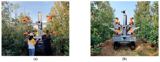
Figure 21.
Field test prototype and working environment. (a) Scheme A. (b) Scheme B.
3.2.2. Multi-Round Picking Singularity Rate Test
The harvesting process of the four-arm apple harvesting robot is shown in Figure 22, which mainly includes five steps: (1) Aiming, (2) Approaching, (3) Swallowing, (4) Closing, and (5) Avoiding. When picking the target fruit, we define the ratio of the number of fruits that cause the robot to have a singular configuration to the total number of harvested fruits as the singularity rate when repeating these five steps. The results are shown in Table 4.
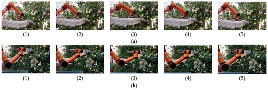
Figure 22.
The harvesting process of the upper and lower manipulators of the apple harvesting robot. (a) The picking process of the upper side manipulator. (b) The picking process of the lower side manipulator. (1) Aiming. (2) Approaching. (3) Swallowing. (4) Closing. (5) Avoiding.

Table 4.
Statistical results of singular occurrence during the harvesting process.
According to the statistical results of Table 4, it can be found that the singularity rate of Scheme A is about 26.18%, while the singularity rate of Scheme B is about 13.22%, which is about 12.96% lower than that of Scheme A. In addition, in the five steps of the harvesting process, both of the two schemes showed that the most singular configurations were generated when the end was swallowed, followed by concession and proximity, and no singularity occurred during the end closure process. This shows that whether the manipulator produces a singular configuration in addition to its own structural influence, its picking steps will also affect the singularity rate.
3.2.3. Multi-Round Picking Success Rate Test
The success rate of harvesting is a comprehensive index to measure the performance of the harvesting robot. In this paper, the success rate of harvesting is defined as the ratio of the number of fruits successfully picked within the scope of robot operation to the number of fruits that should be picked. When the harvesting robot has finished picking, and singularity occurs during the avoiding step (Figure 22), we consider that the fruit has been successfully harvested.
Because the operating conditions have a great influence on the success rate of harvesting, this paper chooses other harvesting robots developed for high-spindle apple orchards as the comparison objects, and there are some differences in canopy conditions and fruit density. The comparison of field test results is shown in Table 5.

Table 5.
Performance comparison of different apple harvesting robots.
By comparison, the success rate of Scheme A is 80.49%, which has the best performance in terms of picking success rate. For Scheme B, the success rate is 72.33%. The reason is that there are large differences in canopy conditions and fruit distribution among different tree rows in the experimental orchard, and the experimental conditions of Scheme B are more complex than those of Scheme A, resulting in a lower actual harvest success rate than Scheme A.
The results of Table 6 show the reasons for the failure of harvesting in Scheme A and Scheme B, including position error, obstacle, singularity, and attachment failure. Meanwhile, the harvesting failure caused by singularity includes two cases: the fruit that does not meet the non-singular condition is removed, and the manipulator’s action is stopped. Although affected by the working environment, Scheme B has more failures in positioning errors and obstacles, which also leads to a significant reduction in the success rate of harvesting. However, compared with Scheme A, Scheme B performs better in solving singular problems.

Table 6.
Comparison of the causes of harvesting failure between Scheme A and Scheme B.
Therefore, in view of the high-spindle environmental constraints and the singularity of the multi-joint arm, the two harvesting robot configuration design schemes proposed in this study have a good overall performance. Among them, Scheme B is more prominent in solving singular problems, but the success rate of harvesting is greatly affected by the operating environment, which needs to be improved in subsequent research.
4. Conclusions
Aiming at the problem of singular configuration caused by the use of multi-joint arms in a high-spindle environment, two harvesting system architecture schemes that can meet the constraints of fruit spatial distribution and reduce the singularity of harvesting robot operation were proposed in this paper. The conclusions are summarized as follows:
- (1)
- Firstly, in order to make the harvesting robot meet the requirements of complex canopy and non-uniform fruit distribution, a generalized mathematical model was established according to the spatial distribution characteristics of high-spindle orchard fruits, which was used as the design constraint.
- (2)
- Then, two design constraints-based schemes were proposed. Based on the link-joint method, the singular configuration conditions of the harvesting robot in the two schemes were obtained.
- (3)
- Finally, according to the harvesting robot operation scheme, the IK solution and trajectory planning strategy for singular avoidance were proposed to realize the singular configuration judgment and solution in the high-spindle orchard.
- (4)
- The simulation results showed that the singularity rate of Scheme A was 17.098%, while Scheme B was 6.74%. Meanwhile, the picking trajectory planning strategy can effectively solve the problem of velocity fluctuation when the joints pass through the singular region.
- (5)
- In the field experiment, the singularity rate of Scheme A was 26.18%, while Scheme B was 13.22%. Affected by the complexity of the testing environment, the success rate of Scheme B was 72.33%, which was lower than Scheme A (80.49%). However, Scheme B performs better in solving singular problems, which is crucial in this study. Therefore, Scheme B is better than Scheme A.
In the future, we will focus on how to improve the success rate of Scheme B. The increase in the complexity of the environment leads to the increase in the probability of position error and obstacle of Scheme B; hence, it will be solved by improving the performance of positioning and path planning algorithms under the complex canopy. At the same time, we find that there is a correlation between the singularity configuration of the harvesting robot and the setting of the picking steps. It is necessary to explore the rationality of the picking steps to optimize the singularity avoidance performance of the multi-joint four-arm harvesting robot.
Author Contributions
Conceptualization, X.L. and J.L.; methodology, X.L. and J.L.; validation, X.L., J.L., H.J. and B.X.; formal analysis, X.L. and J.L.; investigation X.L. and J.L.; resources, J.L.; data curation, X.L. and J.G.; writing–original draft preparation, X.L.; writing–review and editing, X.L. and J.L. Funding, J.L. and Y.J. All authors have read and agreed to the published version of the manuscript.
Funding
The work was supported by the Jiangsu Province Science and Technology Plan Special Fund Project (Grant Number: BE2022363), Project of Faculty of Agricultural Engineering of Jiangsu University (Grant Number: NZXB20240103), Guizhou Province Science and Technology Major Special Project (Guizhou Branch [2024] 002), and the Priority Academic Program Development of Jiangsu Higher Education Institutions (No. PAPD2023-87).
Data Availability Statement
The original contributions presented in this study are included in the article. Further inquiries can be directed to the corresponding author.
Conflicts of Interest
The authors declare no conflicts of interest.
References
- Roy, G. Global Apple Production Set To Rebound in 2024. Available online: https://www.producereport.com/article/global-apple-production-set-rebound-2024 (accessed on 10 June 2025).
- Zhang, X.; Du, L.; Zhu, Q. The potential of substituting labors with capitals in apple production under the constraint of increasing labor cost. Res. Agri Cult. Mod. 2020, 41, 484–492. [Google Scholar]
- Huo, X.; Liu, T.; Liu, J.; Wei, Y.; Yao, X.; Mao, X.; Lu, F. 2020 China apple industry development report (simplified version). China Fruit Veg. 2022, 42, 1–6. [Google Scholar]
- Zhang, Z.; Igathinathane, C.; Li, J.; Cen, H.; Lu, Y.; Flores, P. Technology progress in mechanical harvest of fresh market apples. Comput. Electron. Agric. 2020, 175, 105606. [Google Scholar] [CrossRef]
- Duan, L.; Yang, F.; Yan, B. Research progress of apple production intelligent chassis and weeding and harvesting equipment technology. Smart Agric. 2022, 4, 24. [Google Scholar]
- Abhiram, G. The Evolution of Tea Harvesting: A Comprehensive Review of Machinery and Technological Advancements. J. Biosyst. Eng. 2024, 49, 346–367. [Google Scholar] [CrossRef]
- Yang, Y.; Xie, H.; Zhang, K.; Wang, Y.; Li, Y.; Zhou, J.; Xu, L. Design, Development, Integration, and Field Evaluation of a Ridge-Planting Strawberry Harvesting Robot. Agriculture 2024, 14, 2126. [Google Scholar] [CrossRef]
- Williams, H.A.; Jones, M.H.; Nejati, M.; Seabright, M.J.; Bell, J.; Penhall, N.D.; Barnett, J.J.; Duke, M.D.; Scarfe, A.J.; Ahn, H.S. Robotic kiwifruit harvesting using machine vision, convolutional neural networks, and robotic arms. Biosyst. Eng. 2019, 181, 140–156. [Google Scholar] [CrossRef]
- Tibbetts, J.H. Agricultural disruption: New technology, consolidation, may yield production gains, job upheaval. BioScience 2019, 69, 237–243. [Google Scholar] [CrossRef]
- Jin, Y.; Liu, J.; Xu, Z.; Yuan, S.; Li, P.; Wang, J. Development status and trend of agricultural robot technology. Int. J. Agric. Biol. Eng. 2021, 14, 1–19. [Google Scholar] [CrossRef]
- Fu, L.; Tola, E.; Al-Mallahi, A.; Li, R.; Cui, Y. A novel image processing algorithm to separate linearly clustered kiwifruits. Biosyst. Eng. 2019, 183, 184–195. [Google Scholar] [CrossRef]
- Zhang, K.; Lammers, K.; Chu, P.; Li, Z.; Lu, R. An automated apple harvesting robot—From system design to field evaluation. J. Field Robot. 2024, 41, 2384–2400. [Google Scholar] [CrossRef]
- Silwal, A.; Davidson, J.R.; Karkee, M.; Mo, C.; Zhang, Q.; Lewis, K. Design, integration, and field evaluation of a robotic apple harvester. J. Field Robot. 2017, 34, 1140–1159. [Google Scholar] [CrossRef]
- Li, T.; Xie, F.; Zhao, Z.; Zhao, H.; Guo, X.; Feng, Q. A multi-arm robot system for efficient apple harvesting: Perception, task plan and control. Comput. Electron. Agric. 2023, 211, 107979. [Google Scholar] [CrossRef]
- Joseph, R.; Abhisesh, S.; Cameron, H.; Manoj, K.; Changki, M.; Qin, Z. Proof-of-concept of a robotic apple harvester. In Proceedings of the International Conference on Intelligent Robots and Systems (IROS), Daejeon, Republic of Korea, 9–14 October 2016; pp. 952–972. [Google Scholar]
- Davidson, J.; Silwal, A.; Karkee, M.; Mo, C.; Zhang, Q. Hand-picking dynamic analysis for undersensed robotic apple harvesting. Trans. ASABE 2016, 59, 745–758. [Google Scholar]
- Polic, M.; Tabak, J.; Orsag, M. Pepper to fall: A perception method for sweet pepper robotic harvesting. Intell. Serv. Robot. 2022, 15, 193–201. [Google Scholar] [CrossRef]
- Yoshida, T.; Onishi, Y.; Kawahara, T.; Fukao, T. Automated harvesting by a dual-arm fruit harvesting robot. ROBOMECH J. 2022, 9, 19. [Google Scholar] [CrossRef]
- SepúLveda, D.; Fernández, R.; Navas, E.; Armada, M.; González-De-Santos, P. Robotic aubergine harvesting using dual-arm manipulation. IEEE Access 2020, 8, 121889–121904. [Google Scholar] [CrossRef]
- Xiong, Z.; Feng, Q.; Li, T.; Xie, F.; Liu, C.; Liu, L.; Guo, X.; Zhao, C. Dual-manipulator optimal design for apple robotic harvesting. Agronomy 2022, 12, 3128. [Google Scholar] [CrossRef]
- Wang, H.; Hohimer, C.J.; Bhusal, S.; Karkee, M.; Mo, C.; Miller, J.H. Simulation as a tool in designing and evaluating a robotic apple harvesting system. IFAC-Pap. 2018, 51, 135–140. [Google Scholar] [CrossRef]
- Zhou, K.; Xia, L.; Liu, J.; Qian, M.; Pi, J. Design of a flexible end-effector based on characteristics of tomatoes. Int. J. Agric. Biol. Eng. 2022, 15, 13–24. [Google Scholar] [CrossRef]
- Yang, S.; Ji, J.; Cai, H.; Chen, H. Modeling and force analysis of a harvesting robot for button mushrooms. IEEE Access 2022, 10, 78519–78526. [Google Scholar] [CrossRef]
- Pi, J.; Liu, J.; Zhou, K.; Qian, M. An octopus-inspired bionic flexible gripper for apple grasping. Agriculture 2021, 11, 1014. [Google Scholar] [CrossRef]
- Ji, W.; Qian, Z.; Xu, B.; Tang, W.; Li, J.; Zhao, D. Grasping damage analysis of apple by end-effector in harvesting robot. J. Food Process Eng. 2017, 40, e12589. [Google Scholar] [CrossRef]
- Chen, K.; Li, T.; Yan, T.; Xie, F.; Feng, Q.; Zhu, Q.; Zhao, C. A soft gripper design for apple harvesting with force feedback and fruit slip detection. Agriculture 2022, 12, 1802. [Google Scholar] [CrossRef]
- Au, C.; Barnett, J.; Lim, S.H.; Duke, M. Workspace analysis of Cartesian robot system for kiwifruit harvesting. Ind. Robot. Int. J. Robot. Res. Appl. 2020, 47, 503–510. [Google Scholar] [CrossRef]
- Arikapudi, R.; Vougioukas, S.G. Robotic tree-fruit harvesting with telescoping arms: A study of linear fruit reachability under geometric constraints. IEEE Access 2021, 9, 17114–17126. [Google Scholar] [CrossRef]
- Li, Y.; Wu, S.; He, L.; Tong, J.; Zhao, R.; Jia, J.; Chen, J.; Wu, C. Development and field evaluation of a robotic harvesting system for plucking high-quality tea. Comput. Electron. Agric. 2023, 206, 107659. [Google Scholar] [CrossRef]
- Jiang, Y.; Liu, J.; Wang, J.; Li, W.; Peng, Y.; Shan, H. Development of a dual-arm rapid grape-harvesting robot for horizontal trellis cultivation. Front. Plant Sci. 2022, 13, 881904. [Google Scholar] [CrossRef]
- Xie, F.; Guo, Z.; Li, T.; Feng, Q.; Zhao, C. Dynamic Task Planning for Multi-Arm Harvesting Robots Under Multiple Constraints Using Deep Reinforcement Learning. Horticulturae 2025, 11, 2311–7524. [Google Scholar] [CrossRef]
- Zhang, F.; Zhao, Y. Kinematics and singularity analysis of UR5 robot. J. Hebei Univ. Sci. Technol. 2019, 40, 51–59. [Google Scholar]
- Avigad, G.; Salomon, S.; Kahani, A.; Koster, Y. Robotic Fruit Harvesting Machine with Fruit-Pair Picking and Hybrid Motorized-Pneumatic Robot Arms. U.S. Patent No 11,477,942, 25 October 2022. [Google Scholar]
- Curt, S.; Jacob, S.; Rich, M. End Effector for Robotic Harvesting. US2022192094A1. 2022. Available online: https://patents.google.com/patent/US20170273241A1/en (accessed on 10 June 2025).
- Yan, L.; Yang, Y.; Xu, W.; Vijayakumar, S. Dual-arm coordinated motion planning and compliance control for capturing moving objects with large momentum. In Proceedings of the 2018 IEEE/RSJ International Conference on Intelligent Robots and Systems (IROS), Madrid, Spain, 1–5 October 2018; pp. 7137–7144. [Google Scholar]
- Fischer, D.; Craig, W.; Watada, A.; Douglas, W.; Ashby, B. Simulated in-transit vibration damage to packaged fresh market grapes and strawberries. Appl. Eng. Agric. 1992, 8, 363–366. [Google Scholar] [CrossRef]
- Zhou, J.; He, L.; Karkee, M.; Zhang, Q. Analysis of shaking-induced cherry fruit motion and damage. Biosyst. Eng. 2016, 144, 105–114. [Google Scholar] [CrossRef]
- Li, X.; Sheng, R.; Zhang, L.; Song, T.; Zhang, J. Singular configuration analysis of 6-DOF modular manipulator. Trans. Chin. Soc. Agric. Mach. 2017, 48, 376–382. [Google Scholar]
- Faria, C.; Ferreira, F.; Erlhagen, W.; Monteiro, S.; Bicho, E. Position-based kinematics for 7-DoF serial manipulators with global configuration control, joint limit and singularity avoidance. Mech. Mach. Theory 2018, 121, 317–334. [Google Scholar] [CrossRef]
- Jiang, Z.; Zhou, J.; Han, H.; Wang, Y. Apple Picking Pose Establishment Based on Filtering Point-cloud Noise by RANSAC Fitting. Trans. Chin. Soc. Agric. Mach. 2024, 55, 72–81. [Google Scholar]
- Huang, W.; Miao, Z.; Wu, T.; Guo, Z.; Han, W.; Li, T. Design of and Experiment with a Dual-Arm Apple Harvesting Robot System. Horticulturae 2024, 10, 1268. [Google Scholar] [CrossRef]
Disclaimer/Publisher’s Note: The statements, opinions and data contained in all publications are solely those of the individual author(s) and contributor(s) and not of MDPI and/or the editor(s). MDPI and/or the editor(s) disclaim responsibility for any injury to people or property resulting from any ideas, methods, instructions or products referred to in the content. |
© 2025 by the authors. Licensee MDPI, Basel, Switzerland. This article is an open access article distributed under the terms and conditions of the Creative Commons Attribution (CC BY) license (https://creativecommons.org/licenses/by/4.0/).
