Article

Path Planning and Bending Behaviors of 3D Printed Continuous Carbon Fiber Reinforced Polymer Honeycomb Structures

Key Laboratory of Traffic Safety on Track of Ministry of Education, School of Traffic & Transportation Engineering, Central South University, Changsha 410075, China
*
Authors to whom correspondence should be addressed.
Polymers 2023, 15(23), 4485; https://doi.org/10.3390/polym15234485
Submission received: 30 September 2023 / Revised: 9 November 2023 / Accepted: 18 November 2023 / Published: 22 November 2023
(This article belongs to the Special Issue Additive Manufacturing of Fibre Reinforced Polymer Composites)

Abstract

:
Continuous fiber reinforced polymer composites are widely used in load-bearing components and energy absorbers owing to their high specific strength and high specific modulus. The path planning of continuous fiber is closely related to its structural defects and mechanical properties. In this work, continuous fiber reinforced polymer honeycomb structures (CFRPHSs) with different printing paths were designed and fabricated via the fused deposition modeling (FDM) technique. The investigation of fiber dislocation at path corners was utilized to analyze the structural defects of nodes caused by printing paths. The lower stiffness nodes filled with pure polymer due to fiber dislocation result in uneven stiffness distribution. The bending performance and deformation modes of CFRPHSs with different printing paths and corresponding pure polymer honeycomb structures were investigated by three-point bending tests. The results showed that the enhancement effect of continuous fibers on the bending performance of honeycomb structures was significantly affected by the printing paths. The CFRPHSs with a staggered trapezoidal path exhibited the highest specific load capacity (68.33 ± 2.25 N/g) and flexural stiffness (627.70 ± 38.78 N/mm). In addition, the fiber distributions and structural defects caused by the printing paths determine the stiffness distribution of the loading region, thereby affecting the stress distribution and failure modes of CFRPHSs.

1. Introduction

Due to their lightweight, high strength, and superior energy absorption capacity, honeycomb structures are widely used as load-bearing components and energy absorbers in the forms of sandwich structures and thin-walled structures, owing great application potential in many industrial fields such as aerospace, automobile, and construction [1,2,3,4,5]. The macroscopic performance of honeycomb structures depends on the structural design of their cells and material selection [6,7,8]. With the advancement of design, numerous cells with various forms have been applied in the evolution of honeycomb structures, such as Kagome [9], re-entrant [10], chiral honeycombs [11], etc. The materials of honeycomb structures have also expanded from traditional metals and wood to various newly developed composites, such as polymer composites with excellent mechanical properties and lightweight performance [12,13,14].
Adding continuous fibers as reinforcement in polymers could significantly improve the specific strength and modulus while maintaining their lightweight performance [15,16,17,18]. Traditional preparation methods of continuous fiber reinforced polymers (CFRPs), such as hot press molding [19], vacuum-assisted molding [20], and filament winding [21], require complicated multi-step processes and expensive manufacturing equipment, while the manufacturing of honeycomb structures commonly needs custom molds and subsequent bonding processes [22,23]. These factors became obstacles to the development of continuous fiber reinforced polymer honeycomb structures (CFRPHSs). However, 3D printing techniques with high design freedoms and multi-scale molding capabilities allow a non-mold-based approach to manufacturing structures with customized materials and complex geometric shapes, providing the possibility for the integrated manufacturing of CFRPHSs [24,25,26]. According to the ISO/ASTM 52900 standard, 3D printing technologies are divided into seven types, among which material extrusion (MEX) technology is very suitable for 3D printing of polymers [27,28]. Fused deposition modeling (FDM), as one of the most widely used MEX technologies, with rapid prototyping and low-cost characteristics, combines continuous fibers with polymer matrix [29,30,31]. Many researchers have introduced CFRPs with lightweight and high specific strength features into the design of honeycomb structures via the FDM technique [32,33,34]. For example, Kentaro et al. [35] printed a series of CFRPHSs with hexagon, rhombus, rectangle, and circle core shapes through the FDM technique. The experimental results showed that bending properties increased with the increase of core density, and the CFRPHSs with a rhombus core shape exhibited the strongest bending properties. Dou et al. [36] fabricated hexagon-filled CFRPHSs and studied their in-plane compression properties. The results showed the specific energy absorption of composite honeycomb was 186.58% and 596.84% higher than that of pure polymer matrix and aluminum alloy, respectively.
In addition, the printing path also had a crucial influence on the arrangement and orientation of continuous fibers and further affects the mechanical properties of the structure [37,38,39]. Some researchers have tried to improve the manufacturing process and mechanical properties of CFRPHSs by printing path planning [40,41]. For most FDM-based 3D printers without fiber cutting and jumping functions, the one-stroke printing path planning was an inevitable choice to achieve cyclic printing in the height direction [42,43]. Based on one-stroke printing path planning, Quan et al. [44] designed and fabricated a group of auxetic honeycomb-filled CFRPHSs. The compressive stiffness and energy absorption of the CFRPHSs were increased by 86.3% and 100%, respectively, compared to the structures made of pure polymer matrix. Dong et al. [45] investigated the influences of printing paths on the tensile properties of diamond-filled CFRPHSs. The improved trapezoid-like path allowed an even fiber distribution without weak nodes in the CFRPHSs, exhibiting excellent tensile strength.
Depending on the path planning, there were various situations of the fiber crossing at the nodes of the honeycomb structures [46]. The nodes without fiber interlacement might result in structurally weak regions [45], and printing path corners inevitably appeared at the nodes owing to the structural features of the honeycomb. Some printing defects, including fiber dislocation and the absence of fiber, can occur at the corner paths, which might further exacerbate the structural defects of the CFRPHSs [47,48,49,50]. The details of the fiber distributions and printing defects were effectively displayed on the honeycomb structures, especially at the nodes. These fiber distributions and structural defects caused by printing paths affect the mechanical behavior of CFRPHSs during loading. However, to the best of the authors’ knowledge, only a small amount of literature has investigated how the printing path planning affects 3D printed continuous fiber reinforced structural defects and further mechanical properties.
In this study, diamond-filled CFRPHSs with four different printing paths were designed and fabricated. Three corners (45°, 90°, and 135°) that appeared in the printing paths were selected to investigate the fiber dislocation phenomena at the path corners. Three-point bending tests and morphological analysis were conducted to investigate the influence of the printing path and printing defects at path corners on the bending behaviors of CFRPHSs. This study analyzed the mapping relationship between the printing path planning, structural defects, and final structural and mechanical performance, aiming to provide guidance for the printing path planning of 3D printed CFRPHSs with high performance.

2. Materials and Methods

2.1. Design and Fabrication

In this study, a honeycomb structure with a diamond configuration was designed to investigate bending behaviors and failure mechanisms, as shown in Figure 1a. The honeycomb core consisted of a repeating arrangement of unit diamond cells. The included angle of the diamond cell was 90°; the length (L) and width (W) of the CFRPHSs were determined by the diamond cell length (P); the height (H) of the CFRPHSs was 10 mm.
Polyamide (PA) filament (Polymaker Inc., Changshu, China) with a diameter of 1.75 mm was adopted as the polymer matrix of the CFRPHSs. The continuous carbon fiber (CCF) (HTA40-E15-1K, Toho Tenax Co., Ltd., Tokyo, Japan) was used as the reinforced fiber, which was a flat fiber bundle with a width of 0.80 mm. Before printing, the filaments were sealed and stored at 20 °C. According to the instructions from the materials supplier, the mechanical properties of the PA filament and CCF are listed in Table 1.
A commercial 3D printer (COMBOT-200, Fibertech Technology Development Co., Ltd., Shaanxi China), based on the FDM technique, was used to fabricate the CFRPHSs. The schematic representation of the 3D printing process is shown in Figure 1b. The PA filament (blue) and CCF (black) were simultaneously fed into the extrusion head through these two feed ports, respectively. The in situ impregnation of CFRPs was realized in the heated mixing chamber. Then, CFRPs were extruded onto the printing bed and solidified rapidly. With the relative motion of the printing nozzle and the printing bed, the subsequent CFRPs were dragged out from the printing nozzle, ensuring the continuity of the printing process. The models of the CFRPHSs were sliced before manufacturing and the slice data was recorded in the G-codes developed by our team, including the printing paths, geometrical parameters, and printing parameters. For all samples in this study, the printing nozzle temperature was 260 °C, and the printing bed temperature was 50 °C. The printing speed was 180 mm/min, and the layer height was 0.4 mm.
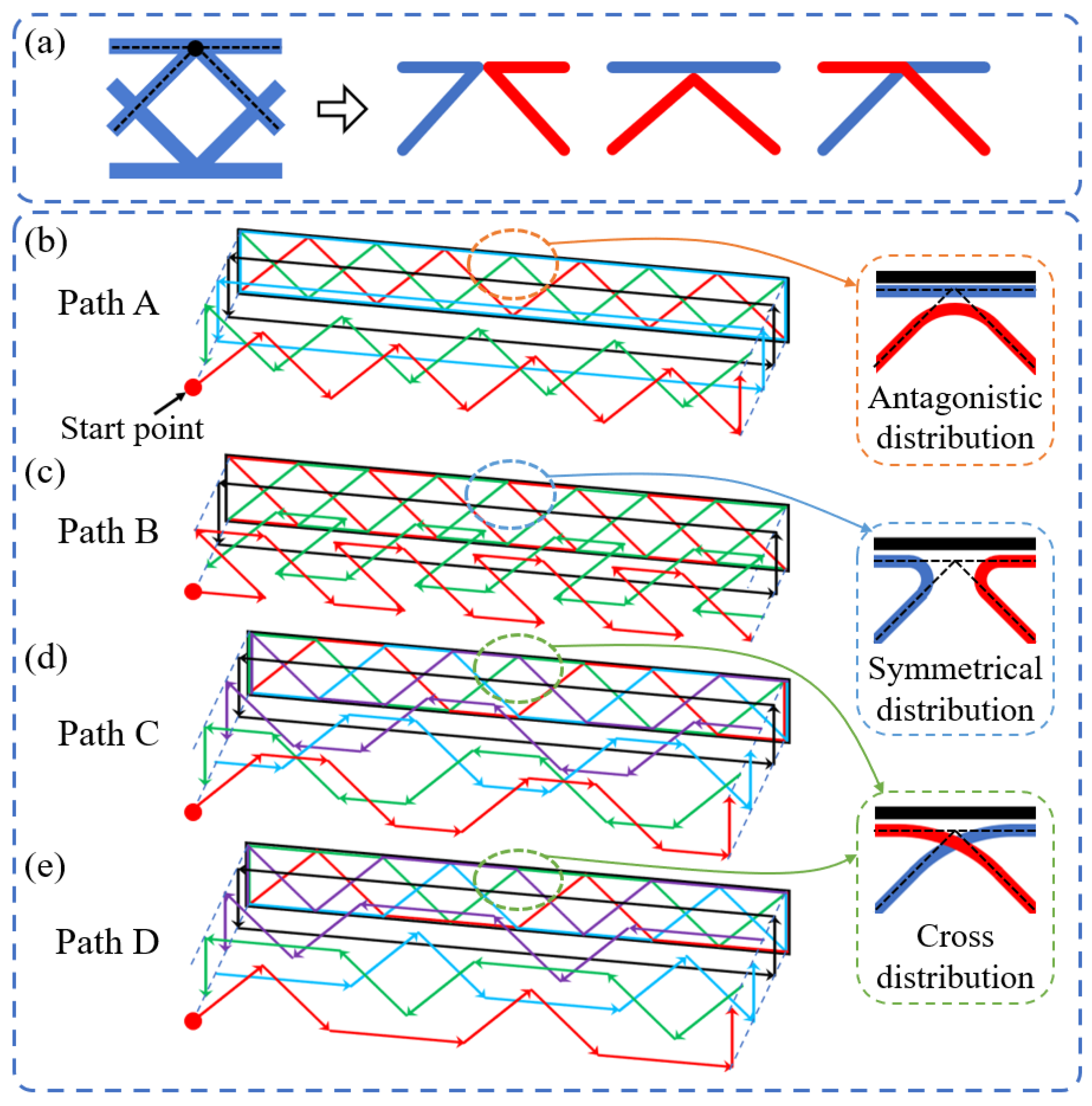
One-stroke printing path planning was required for the CFRPHSs to ensure the integrity of CCF due to the printer’s lack of jumping and fiber-cutting features [51]. The manufacturing of 3D printed CFRPHSs was based on the layer-by-layer stacking mechanism of FDM, which was only needed to design a single-layer printing path and print the same single-layer printing path repeatedly in Z-direction. Based on the flexibility of the 3D printing path planning, the printing paths at the nodes lapped between the core and face sheets of the CFRPHSs could be crossing or non-crossing, resulting in fiber interleaving or adjacency [45,46]. Figure 2a shows three printing path strategies at the nodes. According to these different path strategies, four printing paths for the diamond-filled CFRPHSs were designed in this study, as shown in Figure 2b–e. These complete single-layer paths were decomposed into multiple branches distinguished by different colors according to the printing order; these branches were printed successively from the outside to the inside. The combined graphs of the path branches were shown at each bottom. The printing nozzle began from the start point of a single-layer printing path and moved along the arrow direction during printing. After completing the one-stroke path of each layer, the printing nozzle returned to the start point. Then, the printing bed moved downward by a layer height along the Z-direction to repeat the print for the next layer. In the whole printing process, the continuous fibers remained intact. On the right side of these printing paths, the corresponding fiber distribution modes at the nodes were displayed, including antagonistic distribution, symmetrical distribution, and cross-distribution. In addition, pure polymer honeycomb structures (PPHSs) were also prepared with the same geometrical parameters and printing parameters.

2.2. Experimental Methods

The fiber dislocation inevitably appeared at the path corners in the CFRP’s printing process. The morphology of the fiber dislocation at different path corners was recorded by a digital camera (5D mark IV, Canon, Tokyo, Japan). ImageJ version 1.53t software was used to measure the actual angle and position of the fibers at these corners, and a quantitative evaluation method of fiber dislocation was used to analyze the obtained data.
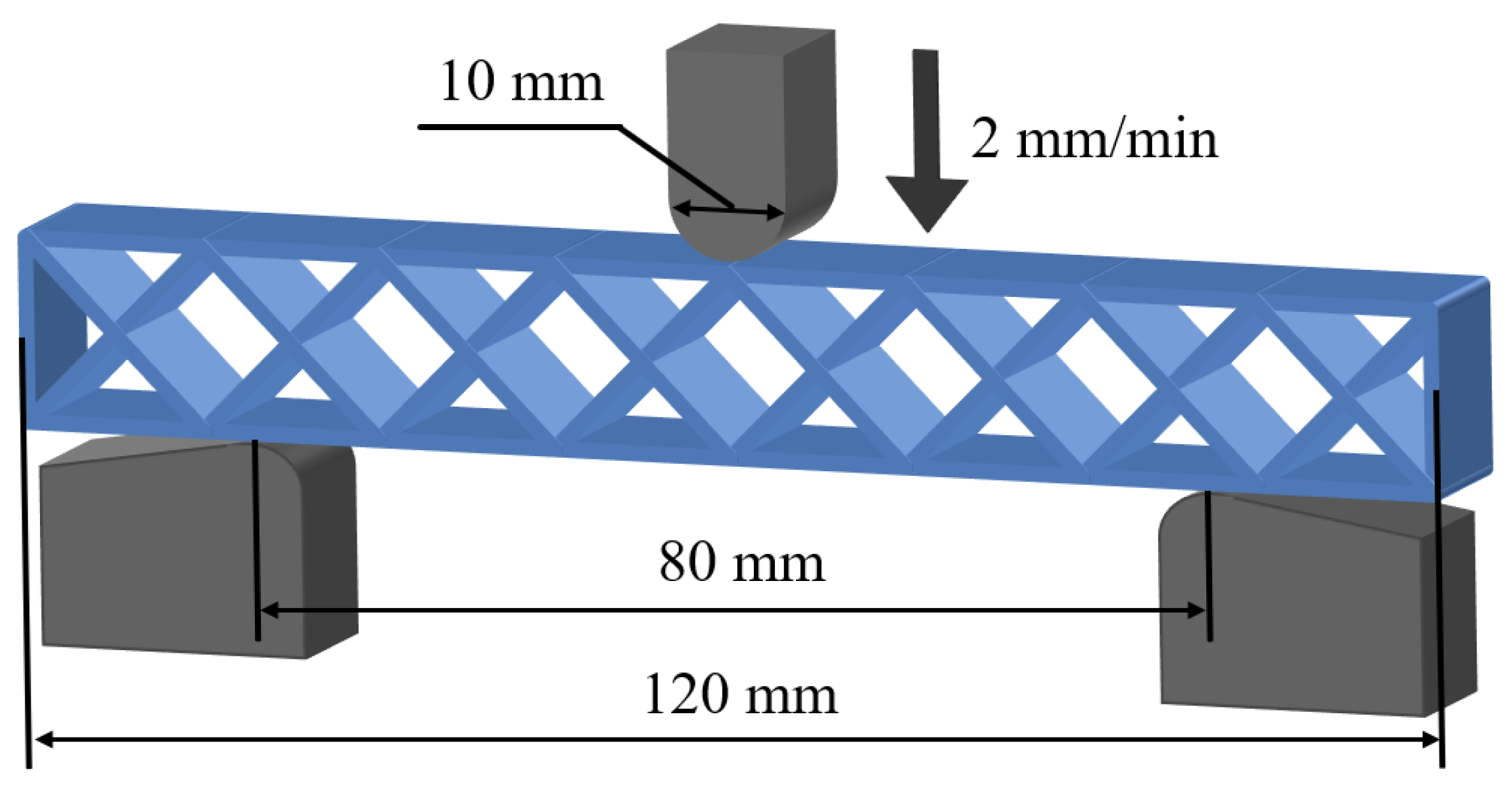
Honeycomb structures are subjected to a complex stress state during the bending process, and these are helpful in studying the influence of the printing path on mechanical behaviors [52,53]. Therefore, the three-point bending tests were performed on a universal material testing machine (E44, MTS Co., Eden Prairie, MN, USA) to investigate the bending properties and failure modes of 3D printed CFRPHSs with different printing paths and PPHSs. The schematic diagram of the three-point bending test is shown in Figure 3. The span between the supports was 80 mm, and the loading roller radius was 5 mm [35,54]. The displacement loading was applied to the samples with a speed of 2 mm/min, and the maximum displacement was 20 mm. The load and displacement data of all tests were automatically collected in the data acquisition system, and the whole test process was recorded by the digital camera. The failure areas of the samples were characterized through an optical microscope (AO-3M150GS, AOSVI, Shenzhen, China). According to the measured load-displacement curves, several indicators were used to quantify the bending properties, including specific load capability and flexural stiffness. The specific load capability (SLC) was calculated by dividing a maximum peak load by the structure mass:
S L C = F p e a k m
where m is the mass of the sample, and F p e a k is the maximum peak load. The flexural stiffness was calculated as the slope of the load-displacement curve in a low displacement regime where the curve was almost linear. Each group of tests was repeated five times to ensure reliability, and the average results are reported in this study.

3. Results and Discussions

3.1. Investigation of Fiber Dislocation at Path Corners

The corner paths appear at the nodes (i.e., the corners of the honeycomb walls) due to the structural features of honeycomb structures. At the nodes lapped between the core and face sheets in the CFRPHSs, the printing paths are composed of different corner paths distributed in different forms (e.g., crossing or non-crossing), which are the distinctions between different printing paths of the CFRPHSs [45,46]. The printing defects of fiber dislocations are inevitably generated at the corner paths [48,49]. The corner paths with fiber dislocation may cause structural defects at the nodes of the CFRPHSs, which can further affect the mechanical properties and deformation modes.
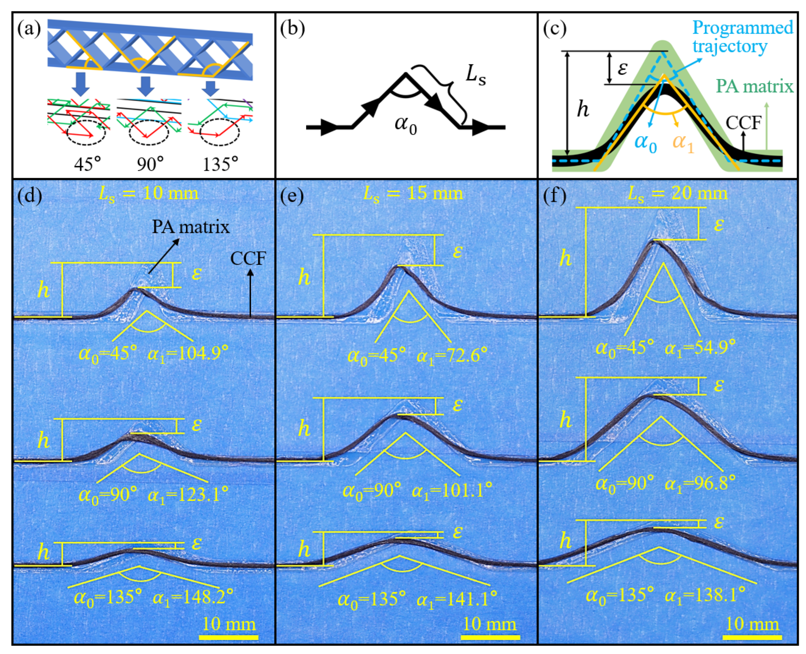
The degree of fiber dislocation was mainly affected by the angle of path corner and the shortest length of straight paths forming the corner [47]. For the diamond-filled CFRPHSs, there were only three kinds of path corners (45°, 90°, and 135°) in all printing paths, as shown in Figure 4a. The shortest straight path ( L s ) of the CFRPHSs was limited by the structural geometric parameters. Here, L s was equal to the diamond cell length (P), as well as the width of the CFRPHSs (W). Thus, a corner path consisting of two equal straight paths ( L s ) is designed in Figure 4b, which could be 45°, 90°, and 135°. Under the default printing process parameters, these corner paths were printed as L s = 10 mm, 15 mm, and 20 mm, corresponding to Figure 4d–f, respectively. Noticeable carbon fiber dislocations at these path corners could be observed. To further quantify the degree of fiber dislocation at these corners and determine the appropriate geometric parameters for the CFRPHSs, the angle distortion ratio (φ) and the height distortion ratio ( δ ) were used as the quantitative evidence, and are expressed as follows:
φ = α 1 α 0 α 0
δ = ε h
where α 0 denotes the programmed angle of the path corner, α 1 refers to the actual angle of the CCF at the path corner, h is the theoretical height of the CCF raised at the corner, and ε is the retraction distance of the CCF at the corner, as shown in Figure 4c.
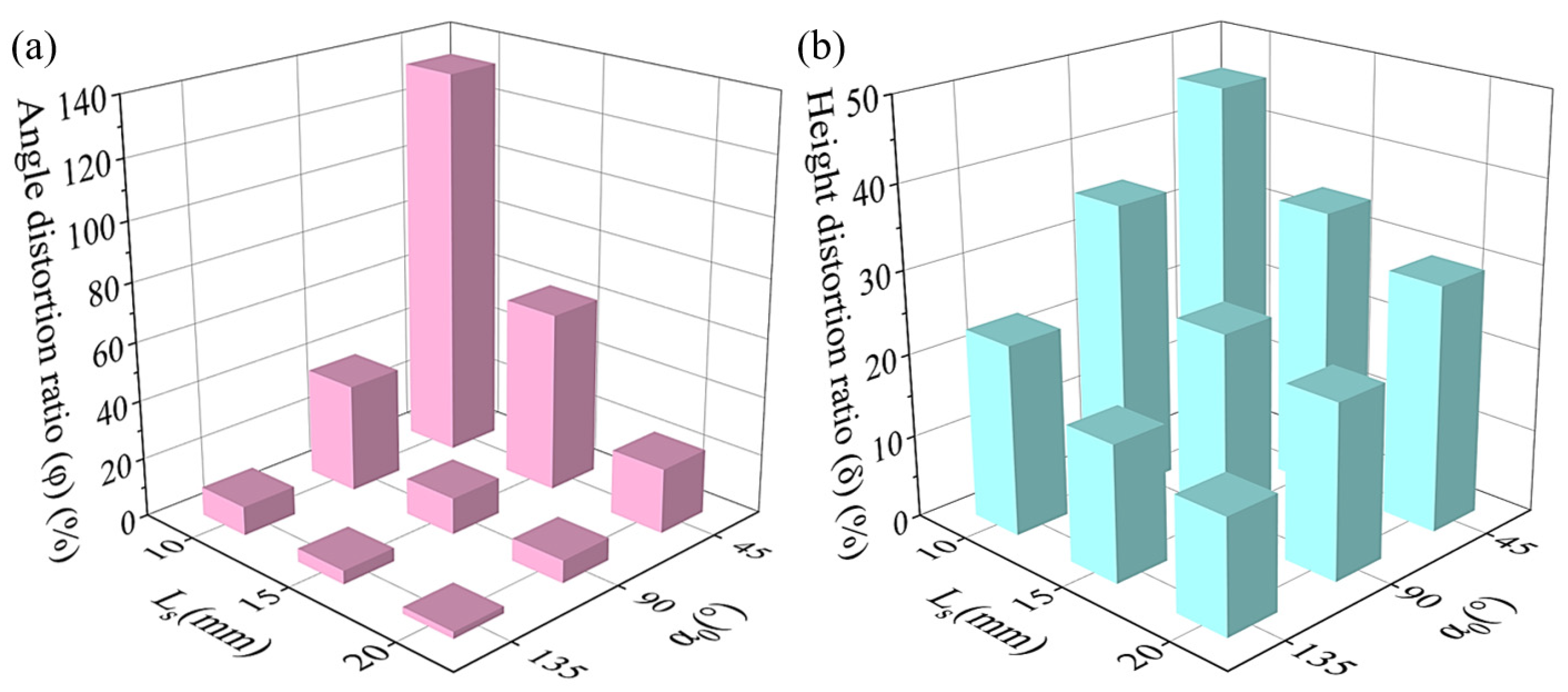
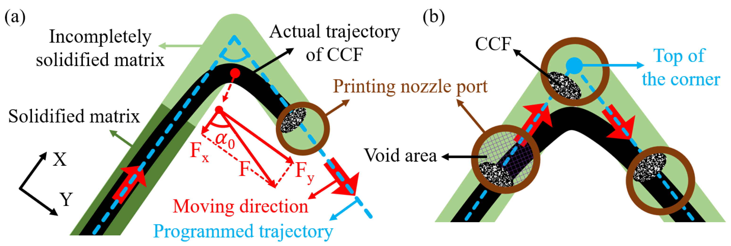
According to Formulas (2) and (3), the calculated values of φ and δ of these path corners are exhibited in Figure 5a,b, respectively. It can be observed that the values of φ and δ increased with the decrease of α 0 , as well as the decrease of L s . According to the schematic diagram in Figure 6a, the incompletely solidified matrix could not constrain the fiber effectively [47], which was the main factor causing the fiber dislocation at the corner paths. A pulling force F, generated by the movement of the nozzle during printing, pulled the subsequent CCF out of the nozzle to ensure the continuity of the printing. After the nozzle turned, the direction of the pulling force F changed, which was parallel to the second straight path. However, there was some incompletely solidified matrix close to the printing nozzle due to the short cooling time and inadequate solidification, which could not provide enough constraints for the CCF at the corner. As a result, the printed CCF at the end of the first straight path was pulled out by the pulling force F. The direction of the first straight path and its vertical direction were defined as the X-direction and the Y-direction, respectively. Fx and Fy are the two vertical components of the pulling force F in the X-direction and Y-direction. When α 0 ≥ 90°, the fiber dislocation is mainly caused by Fy, while Fx along the X-axis positive direction has no negative effect. The vertical component Fy increased as α 0 decreased when F was constant, exacerbating the fiber dislocation. When α 0 < 90°, the CCF, pulled by Fx along the X-axis positive direction, and Fy, exhibited significantly higher angle distortion and height distortion. Therefore, the values of φ and δ were increased with the decrease of α 0 , and they were significantly higher when α 0 = 45°. The length of the incompletely solidified matrix close to the nozzle was almost fixed under the same process conditions. The proportion of the fiber dislocation area in the corner increased with the decrease of L s when the angle was constant. Therefore, both the values of φ and δ increased with the decrease of L s , as shown in Figure 5.
In addition, the fiber could not maintain a fixed position relative to the nozzle port, which was another factor causing fiber dislocation [48], as shown in Figure 6b. To reduce fiber damage during printing, there was a difference between the cross-sectional area of fiber and the nozzle port, resulting in the CCF with a high degree of freedom in the nozzle port. The relative position of CCF could not remain fixed during nozzle turning owing to the high fluidity of the molten polymer matrix. Therefore, the CCF could not reach the top of the corners.
According to the above investigation, the angle distortion ratio of the 45° corner reached 133.1%, and its height distortion ratio reached 45.7% when L s = 10 mm, showing serious printing defects. To maintain the fiber dislocation at relatively low levels, L s could not be less than 15 mm. Moreover, the CFRPHSs show better mechanical properties with increasing filling density, which tended to be with a smaller L s [55]. Therefore, L s was set as 15 mm of the CFRPHSs with different printing paths.

3.2. Effect of Printing Path on Bending Properties

The distribution and orientation of continuous fibers within the CFRPHSs were determined by their printing paths, which affects the mechanical behaviors [56]. To investigate the influence of the printing path on the bending performance of the 3D printed CFRPHSs, three-point bending tests for the CFRPHSs with four printing paths and the PPHSs were carried out. According to the discussions in Section 3.1, L and W of the CFRPHSs were set as 120 mm and 15 mm, respectively. The maximum bending displacement was 20 mm. Figure 7a,b shows the photographs of the bending test samples at displacements of 0 mm and 20 mm, respectively.
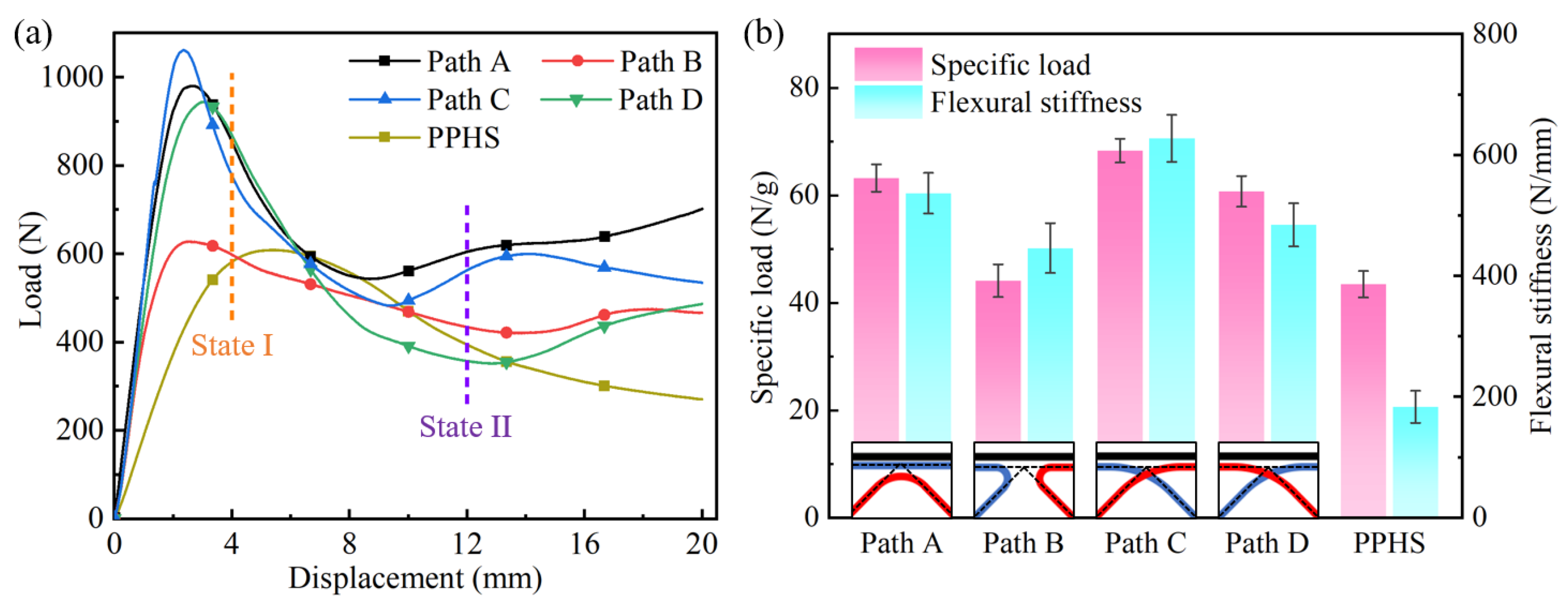
Figure 8a exhibits the load-displacement curves of the CFRPHSs with four printing paths and the PPHSs under three-point bending tests. It can be observed that the load-displacement curves of these CFRPHSs can be divided into three clear stages: the elastic stage, yield stage, and plateau stage. The CFRPHSs initially exhibited short-term elastic deformation during the bending process, and the load increased almost linearly up to the initial peak load, which was the elastic stage. After elastic deformation, the CFRPHSs quickly entered the yield stage. In this stage, the load dropped rapidly to a relatively low value with the progressive failure of structures. Subsequently, the load-displacement curves presented a plateau stage accompanied by small fluctuations in the load. Meanwhile, the deformation stages of the PPHSs were similar to those of the CFRPHSs.
The specific load capability and flexural stiffness of these CFRPHSs and the PPHSs were calculated to further evaluate the bending properties, as shown by the results in Figure 8b and Table 2. It was observed that the addition of continuous fiber greatly improves the flexural stiffness of honeycomb structures. In particular, the CFRPHSs with path C exhibited the highest flexural stiffness (627.70 ± 38.78 N/mm), which was 241.8% higher than the PPHSs. However, the enhancement effect of continuous fiber on specific load capability was more significantly influenced by the printing paths. The CFRPHSs with path C showed the highest specific load capability (68.33 ± 2.25 N/g), while the specific load capability of the CFRPHSs with path B (44.12 ± 3.04 N/g) was close to that of the PPHSs (43.48 ± 2.46 N/g). Therefore, the printing paths would affect the improvement effect of continuous fibers on the bending performance of honeycomb structures.
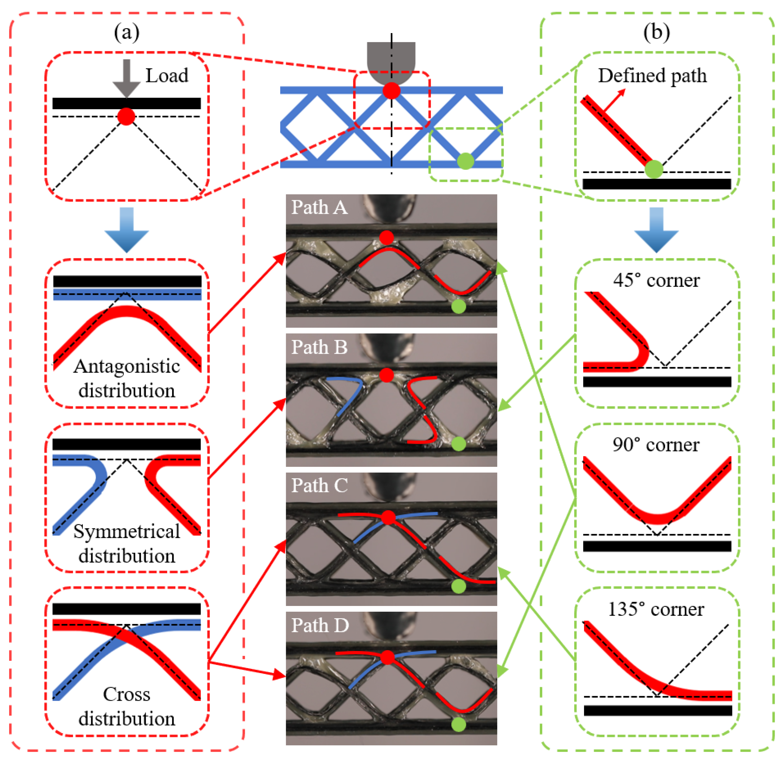
During the bending process, the upper face sheet was directly subjected to the load, whereas the honeycomb core showed supporting and strengthening effects for the face sheet to slow the deformation [57]. Figure 9 further exhibits the fiber distributions of the CFRPHSs in the loading region, distinguished by the color lines. There were three fiber distribution modes at the red node beneath the loading roller, including antagonistic distribution, symmetrical distribution, and cross-distribution, as shown in Figure 9a. The symmetrical distribution consisted of two opposite and symmetrical 45° path corners corresponding to path B. Based on the discussions in Section 3.1, the fiber dislocation of the 45° path corner was the most severe. Thus, a large area of polymer matrix without fiber filling formed at the red node of the CFRPHSs with path B, resulting in a lack of direct support for the compression area of the upper panel because of the low stiffness of pure polymer. It caused the lowest flexural stiffness and specific load capacity of path B. The antagonistic distribution was a 90° path corner with the tip facing the upper face sheet, corresponding to path A. And the cross-distribution was composed of two intersecting 135° path corners, corresponding to paths C and D. The red nodes with these two fiber distribution modes had higher stiffness than the nodes filled with pure polymer and could provide better support to the loading region of the upper face sheets, causing higher flexural stiffness and specific load capacity of the CFRPHSs compared with path B.
In addition, the load acting on the upper face sheet was transmitted to the lower face sheet through continuous fibers distributed in the core. The fiber distribution modes (45°, 90°, and 135° corners) close to the lower face sheet would affect the load transmission from the core to the lower face sheet, as shown by the green nodes in Figure 9b. Among them, the CCF distributed at 135° corner had the largest contact area with the lower face sheet in path C, which could better transfer the load to the lower face sheet and obtain the support from the lower face sheet. Moreover, the staggered trapezoidal path C allowed CCF intersections at all nodes of the CFRPHSs, ensuring a strong connection between core and face sheets [58]. These enabled the structure to have good load transfer performance and fully utilize the supporting function of the honeycomb core. Thus, the CFRPHSs with path C showed the strongest specific load capacity and flexural stiffness compared to other CFRPHSs and PPHSs.
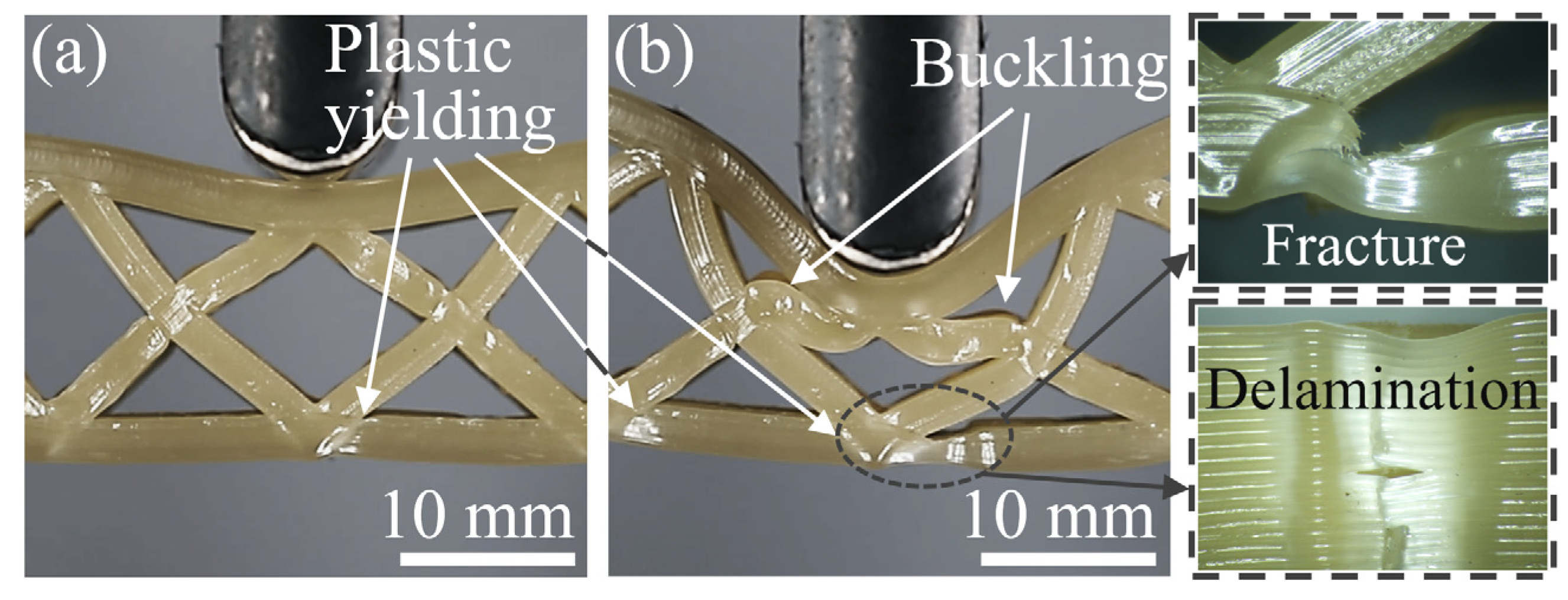
The core and face sheets of honeycomb structures were subjected to a complex stress state during the bending process, accompanied by potential failure modes, including face sheet indentation and core shear. Figure 10 shows the bending deformation states of the PPHSs at displacements of 6 mm and 18 mm, corresponding to the yield stage and the plateau stage, respectively. In Figure 10a, plastic yielding occurred in the lower face sheet near the node, causing the load to begin to decrease. When the displacement reached 12 mm, the PPHSs exhibited indentation failure and core shear failure induced by the core upper member buckling, as shown in Figure 10b. The plastic yielding of the lower face sheet was deepening, accompanied by fracture and delamination. Due to the contact between adjacent honeycomb core members and face sheets, the rate of load decline slowed down, and the PPHSs entered the plateau stage.
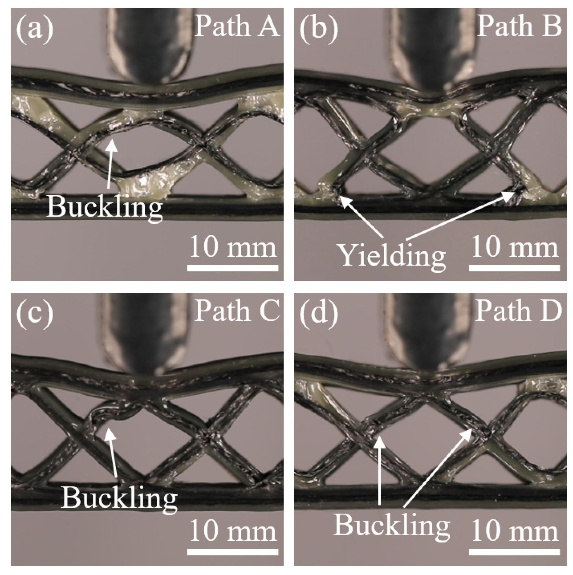
Figure 11 and Figure 12 show the photographs of the bending deformation states of these CFRPHSs at two different moments during the yield and plateau stages, which corresponded to the colored lines in Figure 8a, to further analyze their failure modes. The CFRPHSs at the state I began to enter the yield stage. It can be observed in Figure 11 that the upper face sheet bending beneath the loading roller occurred in all CFRPHSs. Meanwhile, the core shear failure began to occur in the CFRPHSs, resulting in a decrease in their structural bearing capacity. Two possible core shear failure modes are caused by core member buckling or core member yielding, respectively [54]. For paths A, C, and D, the initial failure modes were core shear failure caused by core member buckling, as shown in Figure 11a,c,d. The degrees of core member buckling in these CFRPHSs were different. Path C, with the most severe core member buckling, resulting in the most rapid drop in state I in the load-displacement curve. However, for path B, two 45° corners with severe fiber dislocation were distributed close to the lower face sheet (see Figure 9b), where the nodes filled with pure polymer had low stiffness, resulting in yield failure easily occurring at the end of core members, as shown in Figure 11b. The core shear failure caused by yielding had a smaller effect on the support of the honeycomb core to the upper face sheet than that caused by buckling, maintaining the load of path B declining at a slower rate. Therefore, the core shear failure modes of the CFRPHSs were affected by fiber distribution modes at the nodes. The rate of load decline in the yield stage was determined by the mode and degree of core shear failure.
At state I I , the CFRPHSs began to enter the plateau stage. Indentation failure occurred on the upper face sheets beneath the loading rollers, and core shear failure further deepened in all CFRPHSs, as shown in Figure 12. It could be observed that the CFRPHSs with paths A, C, and D exhibited indentation failure induced by the core upper member buckling (see Figure 12a,c,d), while the indentation failure of path B was induced by the core lower member yielding (see Figure 12b). The results indicated that the antagonistic distribution and cross-distribution of paths A, C, and D endowed their nodes with good stiffness, providing better support to the loading region. Thus, the stress concentration was close to the upper face sheet in the early stage in the core members, which finally resulted in core shear failure on the upper side caused by core member buckling in the plateau stage. Their failure mode was similar to that of PPHSs. However, for path B, the symmetrical distribution and the 45° corners close to the lower face sheet had severe fiber dislocation, causing the low-stiffness nodes to be filled with pure polymer and the uneven stiffness distribution in the loading region. The uneven stiffness distribution led to a stress concentration in the core members close to the lower face sheet, and the end of core members yielded easily, ultimately resulting in core shear failure on the lower side. Thus, depending on the printing paths, the fiber distribution modes, and structural defects determined the stiffness distribution in the loading region, further affecting the stress concentration regions as well as the locations and types of core shear failure in the CFRPHSs.
In addition, some core members and face sheets touched each other with the deepening indentation failure and core shear failure, causing structural densification. Therefore, the bending loads of these CFRPHSs rose in a small amplitude after state I I , as shown in Figure 8a. Moreover, combined with the microscopic morphologies after unloading in Figure 12, severe plastic deformation and damage of the polymer matrix, as well as obvious fiber breakage and fiber detachment from the matrix, could be observed in the areas of core shear failure, which caused irreversible structural failure and a decrease in the bearing capacity.

4. Conclusions

In this study, diamond-filled continuous fiber reinforced polymer honeycomb structures (CFRPHSs) with different printing paths were designed and fabricated via the FDM technique. The fiber dislocation at the path corners was investigated to characterize the structural defects of the CFRPHSs caused by the printing path. The bending behaviors and failure modes of the CFRPHSs with the different printing paths and pure polymer honeycomb structures (PPHSs) were studied by three-point bending tests. The results showed that the fiber distribution modes and structural defects determined the stress concentration regions and core shear failure modes of the CFRPHSs. This study revealed the mapping relationship between the printing path planning, structural defects, and structural and mechanical performance, providing references for the printing path optimization of the 3D printed CFRPHSs with high performance. The main conclusions can be drawn as follows:
(1)
There were three fiber distribution modes at the nodes lapped between the core and face sheets of the CFRPHSs, including symmetrical distribution, antagonistic distribution, and cross distribution, which were determined by the printing paths.
(2)
The structural defects at the nodes of the CFRPHSs were caused by the fiber dislocations at path corners. Low stiffness nodes filled with pure polymer caused by severe fiber dislocation led to uneven stiffness distribution in the loading region of the CFRPHSs. As the angle of the corner and the length of the straight path increased, the degree of fiber dislocation at path corners would decrease.
(3)
The enhancement effect of continuous fibers on the bending performance of honeycomb structures was affected by the printing paths. The path C with staggered trapezoidal distribution ensured a strong connection and good load transfer performance between the core and face sheets of the CFRPHSs, fully utilizing the supporting function of the honeycomb core, exhibiting the highest specific load capability (68.33 ± 2.25 N/g) and flexural stiffness (627.70 ± 38.78 N/mm).
(4)
The nodes of the CFRPHSs with fiber antagonistic distribution and cross distribution had good stiffness, providing better support to the loading region, leading to a stress concentration in the upper core and final core shear failure on the upper side caused by core member buckling. The failure mode of these CFRPHSs was similar to that of the PPHSs.
(5)
When the fibers were symmetrically distributed, the low-stiffness nodes filled with pure polymer caused uneven stiffness distribution in the loading region of the CFRPHSs, resulting in concentrated stress in the core members close to the lower face sheet, which ultimately led to yielding at the 45° corners.
This study has guiding significance for the printing path planning of other continuous fiber reinforced polymer two-dimensional cellular structures. It is necessary to carry out finite element simulation studies incorporating fiber path planning for further optimization of structural parameters in future work.

Author Contributions

Conceptualization, K.W.; methodology, Y.P.; validation, H.G.; formal analysis, Y.P.; investigation, D.W. and Y.L.; resources, C.Y.; data curation, D.W. and H.G.; writing—original draft preparation, K.W. and D.W.; writing—review and editing, Y.L.; visualization, C.Y.; supervision, K.W.; project administration, C.Y. All authors have read and agreed to the published version of the manuscript.

Funding

This research was funded by the Hu-Xiang Youth Talent Program (No. 2020RC3009).

Institutional Review Board Statement

Not applicable.

Data Availability Statement

The data presented in this study are available on request from the corresponding author.

Conflicts of Interest

The authors declare no conflict of interest.

References

  1. Zhang, Q.; Yang, X.; Li, P.; Huang, G.; Feng, S.; Shen, C.; Han, B.; Zhang, X.; Jin, F.; Xu, F.; et al. Bioinspired Engineering of Honeycomb Structure—Using Nature to Inspire Human Innovation. Prog. Mater. Sci. 2015, 74, 332–400. [Google Scholar] [CrossRef]
  2. Thomas, T.; Tiwari, G. Crushing Behavior of Honeycomb Structure: A Review. Int. J. Crashworthiness 2019, 24, 555–579. [Google Scholar] [CrossRef]
  3. Carneiro, V.H.; Rawson, S.D.; Puga, H.; Meireles, J.; Withers, P.J. Additive Manufacturing Assisted Investment Casting: A Low-Cost Method to Fabricate Periodic Metallic Cellular Lattices. Addit. Manuf. 2020, 33, 101085. [Google Scholar] [CrossRef]
  4. An, M.-R.; Wang, L.; Liu, H.-T.; Ren, F.-G. In-Plane Crushing Response of a Novel Bidirectional Re-Entrant Honeycomb with Two Plateau Stress Regions. Thin-Walled Struct. 2022, 170, 108530. [Google Scholar] [CrossRef]
  5. Liu, Y.; Wang, J.; Cai, R.; Xiang, J.; Wang, K.; Yao, S.; Peng, Y. Effects of Loading Rate and Temperature on Crushing Behaviors of 3D Printed Multi-Cell Composite Tubes. Thin-Walled Struct. 2023, 182, 110311. [Google Scholar] [CrossRef]
  6. Habib, F.N.; Iovenitti, P.; Masood, S.H.; Nikzad, M. Cell Geometry Effect on In-Plane Energy Absorption of Periodic Honeycomb Structures. Int. J. Adv. Manuf. Technol. 2018, 94, 2369–2380. [Google Scholar] [CrossRef]
  7. Wang, Z. Recent Advances in Novel Metallic Honeycomb Structure. Compos. Part B Eng. 2019, 166, 731–741. [Google Scholar] [CrossRef]
  8. Qi, C.; Jiang, F.; Yang, S. Advanced Honeycomb Designs for Improving Mechanical Properties: A Review. Compos. Part B Eng. 2021, 227, 109393. [Google Scholar] [CrossRef]
  9. Wang, Z.; Lei, Z.; Li, Z.; Yuan, K.; Wang, X. Mechanical Reinforcement Mechanism of a Hierarchical Kagome Honeycomb. Thin-Walled Struct. 2021, 167, 108235. [Google Scholar] [CrossRef]
  10. Zhang, X.; Yang, D. Mechanical Properties of Auxetic Cellular Material Consisting of Re-Entrant Hexagonal Honeycombs. Materials 2016, 9, 900. [Google Scholar] [CrossRef]
  11. Qi, C.; Jiang, F.; Yu, C.; Yang, S. In-Plane Crushing Response of Tetra-Chiral Honeycombs. Int. J. Impact Eng. 2019, 130, 247–265. [Google Scholar] [CrossRef]
  12. Rajak, D.K.; Pagar, D.D.; Menezes, P.L.; Linul, E. Fiber-Reinforced Polymer Composites: Manufacturing, Properties, and Applications. Polymers 2019, 11, 1667. [Google Scholar] [CrossRef] [PubMed]
  13. Ozkan, D.; Gok, M.S.; Karaoglanli, A.C. Carbon Fiber Reinforced Polymer (CFRP) Composite Materials, Their Characteristic Properties, Industrial Application Areas and Their Machinability. In Engineering Design Applications III: Structures, Materials and Processes; Öchsner, A., Altenbach, H., Eds.; Advanced Structured Materials; Springer International Publishing: Cham, Switzerland, 2020; pp. 235–253. ISBN 978-3-030-39062-4. [Google Scholar]
  14. Du, J.; Zhang, H.; Geng, Y.; Ming, W.; He, W.; Ma, J.; Cao, Y.; Li, X.; Liu, K. A Review on Machining of Carbon Fiber Reinforced Ceramic Matrix Composites. Ceram. Int. 2019, 45, 18155–18166. [Google Scholar] [CrossRef]
  15. Li, J.; Durandet, Y.; Huang, X.; Sun, G.; Ruan, D. Additively Manufactured Fiber-Reinforced Composites: A Review of Mechanical Behavior and Opportunities. J. Mater. Sci. Technol. 2022, 119, 219–244. [Google Scholar] [CrossRef]
  16. Kabir, S.M.F.; Mathur, K.; Seyam, A.-F.M. A Critical Review on 3D Printed Continuous Fiber-Reinforced Composites: History, Mechanism, Materials and Properties. Compos. Struct. 2020, 232, 111476. [Google Scholar] [CrossRef]
  17. Dickson, A.N.; Barry, J.N.; McDonnell, K.A.; Dowling, D.P. Fabrication of Continuous Carbon, Glass and Kevlar Fibre Reinforced Polymer Composites Using Additive Manufacturing. Addit. Manuf. 2017, 16, 146–152. [Google Scholar] [CrossRef]
  18. Xiang, J.; Liu, Y.; Wang, J.; Wang, K.; Peng, Y.; Rao, Y.; Matadi Boumbimba, R. Effect of Heat-Treatment on Compressive Response of 3D Printed Continuous Carbon Fiber Reinforced Composites under Different Loading Directions. J. Appl. Polym. Sci. 2023, 140, e53330. [Google Scholar] [CrossRef]
  19. Zhang, Y.; Sun, L.; Li, L.; Wei, J. Effects of Strain Rate and High Temperature Environment on the Mechanical Performance of Carbon Fiber Reinforced Thermoplastic Composites Fabricated by Hot Press Molding. Compos. Part A Appl. Sci. Manuf. 2020, 134, 105905. [Google Scholar] [CrossRef]
  20. Arulappan, C.; Duraisamy, A.; Adhikari, D.; Gururaja, S. Investigations on Pressure and Thickness Profiles in Carbon Fiber-Reinforced Polymers during Vacuum Assisted Resin Transfer Molding. J. Reinf. Plast. Compos. 2015, 34, 3–18. [Google Scholar] [CrossRef]
  21. Boon, Y.D.; Joshi, S.C.; Bhudolia, S.K. Review: Filament Winding and Automated Fiber Placement with In Situ Consolidation for Fiber Reinforced Thermoplastic Polymer Composites. Polymers 2021, 13, 1951. [Google Scholar] [CrossRef]
  22. Ning, H.; Janowski, G.M.; Vaidya, U.K.; Husman, G. Thermoplastic Sandwich Structure Design and Manufacturing for the Body Panel of Mass Transit Vehicle. Compos. Struct. 2007, 80, 82–91. [Google Scholar] [CrossRef]
  23. Chen, X.; Yu, G.; Wang, Z.; Feng, L.; Wu, L. Enhancing Out-of-Plane Compressive Performance of Carbon Fiber Composite Honeycombs. Compos. Struct. 2021, 255, 112984. [Google Scholar] [CrossRef]
  24. Wang, J.; Liu, Y.; Wang, K.; Yao, S.; Peng, Y.; Rao, Y.; Ahzi, S. Progressive Collapse Behaviors and Mechanisms of 3D Printed Thin-Walled Composite Structures under Multi-Conditional Loading. Thin-Walled Struct. 2022, 171, 108810. [Google Scholar] [CrossRef]
  25. Liu, Y.; Tan, Q.; Lin, H.; Wang, J.; Wang, K.; Peng, Y.; Yao, S. Integrated Design and Additive Manufacturing of Lattice-Filled Multi-Cell Tubes. Compos. Sci. Technol. 2023, 243, 110252. [Google Scholar] [CrossRef]
  26. Xie, G.; Wang, K.; Wu, X.; Wang, J.; Li, T.; Peng, Y.; Zhang, H. A Hybrid Multi-Stage Decision-Making Method with Probabilistic Interval-Valued Hesitant Fuzzy Set for 3D Printed Composite Material Selection. Eng. Appl. Artif. Intell. 2023, 123, 106483. [Google Scholar] [CrossRef]
  27. Alexander, A.E.; Wake, N.; Chepelev, L.; Brantner, P.; Ryan, J.; Wang, K.C. A Guideline for 3D Printing Terminology in Biomedical Research Utilizing ISO/ASTM Standards. 3D Print. Med. 2021, 7, 8. [Google Scholar] [CrossRef] [PubMed]
  28. Ekinci, A.; Johnson, A.A.; Gleadall, A.; Engstrøm, D.S.; Han, X. Layer-Dependent Properties of Material Extruded Biodegradable Polylactic Acid. J. Mech. Behav. Biomed. Mater. 2020, 104, 103654. [Google Scholar] [CrossRef] [PubMed]
  29. Zhang, H.; Huang, T.; Jiang, Q.; He, L.; Bismarck, A.; Hu, Q. Recent Progress of 3D Printed Continuous Fiber Reinforced Polymer Composites Based on Fused Deposition Modeling: A Review. J. Mater. Sci. 2021, 56, 12999–13022. [Google Scholar] [CrossRef]
  30. Li, H.; Lou, R.; Liu, B.; Chen, Y.; Wang, Y. Research on the Fusion of Continuous Fiber Reinforced Thermoplastic Filaments for Fused Filament Fabrication. Int. J. Solids Struct. 2023, 276, 112328. [Google Scholar] [CrossRef]
  31. Cheng, P.; Peng, Y.; Wang, K.; Le Duigou, A.; Yao, S.; Chen, C. Quasi-Static Penetration Property of 3D Printed Woven-like Ramie Fiber Reinforced Biocomposites. Compos. Struct. 2023, 303, 116313. [Google Scholar] [CrossRef]
  32. Cheng, P.; Peng, Y.; Li, S.; Rao, Y.; Le Duigou, A.; Wang, K.; Ahzi, S. 3D Printed Continuous Fiber Reinforced Composite Lightweight Structures: A Review and Outlook. Compos. Part B Eng. 2023, 250, 110450. [Google Scholar] [CrossRef]
  33. Cheng, Y.; Li, J.; Qian, X.; Rudykh, S. 3D Printed Recoverable Honeycomb Composites Reinforced by Continuous Carbon Fibers. Compos. Struct. 2021, 268, 113974. [Google Scholar] [CrossRef]
  34. Dou, H.; Ye, W.; Zhang, D.; Cheng, Y.; Huang, K.; Yang, F.; Rudykh, S. Research on Drop-Weight Impact of Continuous Carbon Fiber Reinforced 3D Printed Honeycomb Structure. Mater. Today Commun. 2021, 29, 102869. [Google Scholar] [CrossRef]
  35. Sugiyama, K.; Matsuzaki, R.; Ueda, M.; Todoroki, A.; Hirano, Y. 3D Printing of Composite Sandwich Structures Using Continuous Carbon Fiber and Fiber Tension. Compos. Part A Appl. Sci. Manuf. 2018, 113, 114–121. [Google Scholar] [CrossRef]
  36. Dou, H.; Ye, W.; Zhang, D.; Cheng, Y.; Wu, C. Comparative Study on In-Plane Compression Properties of 3D Printed Continuous Carbon Fiber Reinforced Composite Honeycomb and Aluminum Alloy Honeycomb. Thin-Walled Struct. 2022, 176, 109335. [Google Scholar] [CrossRef]
  37. Huang, Y.; Tian, X.; Wu, L.; Zia, A.A.; Liu, T.; Li, D. Progressive Concurrent Topological Optimization with Variable Fiber Orientation and Content for 3D Printed Continuous Fiber Reinforced Polymer Composites. Compos. Part B Eng. 2023, 255, 110602. [Google Scholar] [CrossRef]
  38. Hou, Z.; Tian, X.; Zhang, J.; Zhe, L.; Zheng, Z.; Li, D.; Malakhov, A.V.; Polilov, A.N. Design and 3D Printing of Continuous Fiber Reinforced Heterogeneous Composites. Compos. Struct. 2020, 237, 111945. [Google Scholar] [CrossRef]
  39. Zhu, W.; Li, S.; Peng, Y.; Wang, K.; Ahzi, S. Effect of Continuous Fiber Orientations on Quasi-Static Indentation Properties in 3D Printed Hybrid Continuous Carbon/Kevlar Fiber Reinforced Composites. Polym. Adv. Technol. 2023, 34, 1565–1574. [Google Scholar] [CrossRef]
  40. Zhang, G.; Wang, Y.; He, J.; Xiong, Y. A Graph-Based Path Planning Method for Additive Manufacturing of Continuous Fiber-Reinforced Planar Thin-Walled Cellular Structures. Rapid Prototyp. J. 2023, 29, 344–353. [Google Scholar] [CrossRef]
  41. Huang, Y.; Fang, G.; Zhang, T.; Wang, C.C.L. Turning-Angle Optimized Printing Path of Continuous Carbon Fiber for Cellular Structures. Addit. Manuf. 2023, 68, 103501. [Google Scholar] [CrossRef]
  42. Zeng, C.; Liu, L.; Bian, W.; Leng, J.; Liu, Y. Compression Behavior and Energy Absorption of 3D Printed Continuous Fiber Reinforced Composite Honeycomb Structures with Shape Memory Effects. Addit. Manuf. 2021, 38, 101842. [Google Scholar] [CrossRef]
  43. Feng, J.; Yao, L.; Lyu, Z.; Wu, Z.; Zhang, G.; Zhao, H. Mechanical Properties and Damage Failure of 3D-Printed Continuous Carbon Fiber-Reinforced Composite Honeycomb Sandwich Structures with Fiber-Interleaved Core. Polym. Compos. 2023, 44, 1980–1992. [Google Scholar] [CrossRef]
  44. Quan, C.; Han, B.; Hou, Z.; Zhang, Q.; Tian, X.; Lu, T.J. 3D Printed Continuous Fiber Reinforced Composite Auxetic Honeycomb Structures. Compos. Part B Eng. 2020, 187, 107858. [Google Scholar] [CrossRef]
  45. Dong, K.; Liu, L.; Huang, X.; Xiao, X. 3D Printing of Continuous Fiber Reinforced Diamond Cellular Structural Composites and Tensile Properties. Compos. Struct. 2020, 250, 112610. [Google Scholar] [CrossRef]
  46. Yamamoto, K.; Luces, J.V.S.; Shirasu, K.; Hoshikawa, Y.; Okabe, T.; Hirata, Y. A Novel Single-Stroke Path Planning Algorithm for 3D Printers Using Continuous Carbon Fiber Reinforced Thermoplastics. Addit. Manuf. 2022, 55, 102816. [Google Scholar] [CrossRef]
  47. Zhang, G.; Wang, Y.; Qiu, W.; Dong, K.; Xiong, Y. Geometric Characteristics of Single Bead Fabricated by Continuous Fiber Reinforced Polymer Composite Additive Manufacturing. Mater. Today Proc. 2022, 70, 431–437. [Google Scholar] [CrossRef]
  48. Liu, J.; Kang, Y.; Ma, C.; Wang, Y. Research on a Fiber Corner Compensation Algorithm in a 3D Printing Layer of Continuous Fiber-Reinforced Composite Materials. Appl. Sci. 2022, 12, 6687. [Google Scholar] [CrossRef]
  49. Zhang, H.; Chen, J.; Yang, D. Fibre Misalignment and Breakage in 3D Printing of Continuous Carbon Fibre Reinforced Thermoplastic Composites. Addit. Manuf. 2021, 38, 101775. [Google Scholar] [CrossRef]
  50. Matsuzaki, R.; Nakamura, T.; Sugiyama, K.; Ueda, M.; Todoroki, A.; Hirano, Y.; Yamagata, Y. Effects of Set Curvature and Fiber Bundle Size on the Printed Radius of Curvature by a Continuous Carbon Fiber Composite 3D Printer. Addit. Manuf. 2018, 24, 93–102. [Google Scholar] [CrossRef]
  51. Cui, Z.; Huang, X.; Jia, M.; Panahi-Sarmad, M.; Hossen, M.I.; Dong, K.; Xiao, X. 3D Printing of Continuous Fiber Reinforced Cellular Structural Composites for the Study of Bending Performance. J. Reinf. Plast. Compos. 2023, 42, 673–684. [Google Scholar] [CrossRef]
  52. Li, T.; Wang, L. Bending Behavior of Sandwich Composite Structures with Tunable 3D-Printed Core Materials. Compos. Struct. 2017, 175, 46–57. [Google Scholar] [CrossRef]
  53. Liu, Z.; Chen, H.; Xing, S. Mechanical Performances of Metal-Polymer Sandwich Structures with 3D-Printed Lattice Cores Subjected to Bending Load. Arch. Civ. Mech. Eng. 2020, 20, 89. [Google Scholar] [CrossRef]
  54. Zeng, C.; Liu, L.; Bian, W.; Leng, J.; Liu, Y. Bending Performance and Failure Behavior of 3D Printed Continuous Fiber Reinforced Composite Corrugated Sandwich Structures with Shape Memory Capability. Compos. Struct. 2021, 262, 113626. [Google Scholar] [CrossRef]
  55. Zárybnická, L.; Machotová, J.; Pagáč, M.; Rychlý, J.; Vykydalová, A. The Effect of Filling Density on Flammability and Mechanical Properties of 3D-Printed Carbon Fiber-Reinforced Nylon. Polym. Test. 2023, 120, 107944. [Google Scholar] [CrossRef]
  56. Wang, T.; Li, N.; Link, G.; Jelonnek, J.; Fleischer, J.; Dittus, J.; Kupzik, D. Load-Dependent Path Planning Method for 3D Printing of Continuous Fiber Reinforced Plastics. Compos. Part A Appl. Sci. Manuf. 2021, 140, 106181. [Google Scholar] [CrossRef]
  57. Cai, L.; Zhang, D.; Zhou, S.; Xu, W. Investigation on Mechanical Properties and Equivalent Model of Aluminum Honeycomb Sandwich Panels. J. Mater. Eng. Perform. 2018, 27, 6585–6596. [Google Scholar] [CrossRef]
  58. Wang, B.; Ming, Y.; Zhou, J.; Xiao, H.; Wang, F.; Duan, Y.; Kazancı, Z. Fabrication of Triangular Corrugated Structure Using 3D Printed Continuous Carbon Fiber-Reinforced Thermosetting Epoxy Composites. Polym. Test. 2022, 106, 107469. [Google Scholar] [CrossRef]
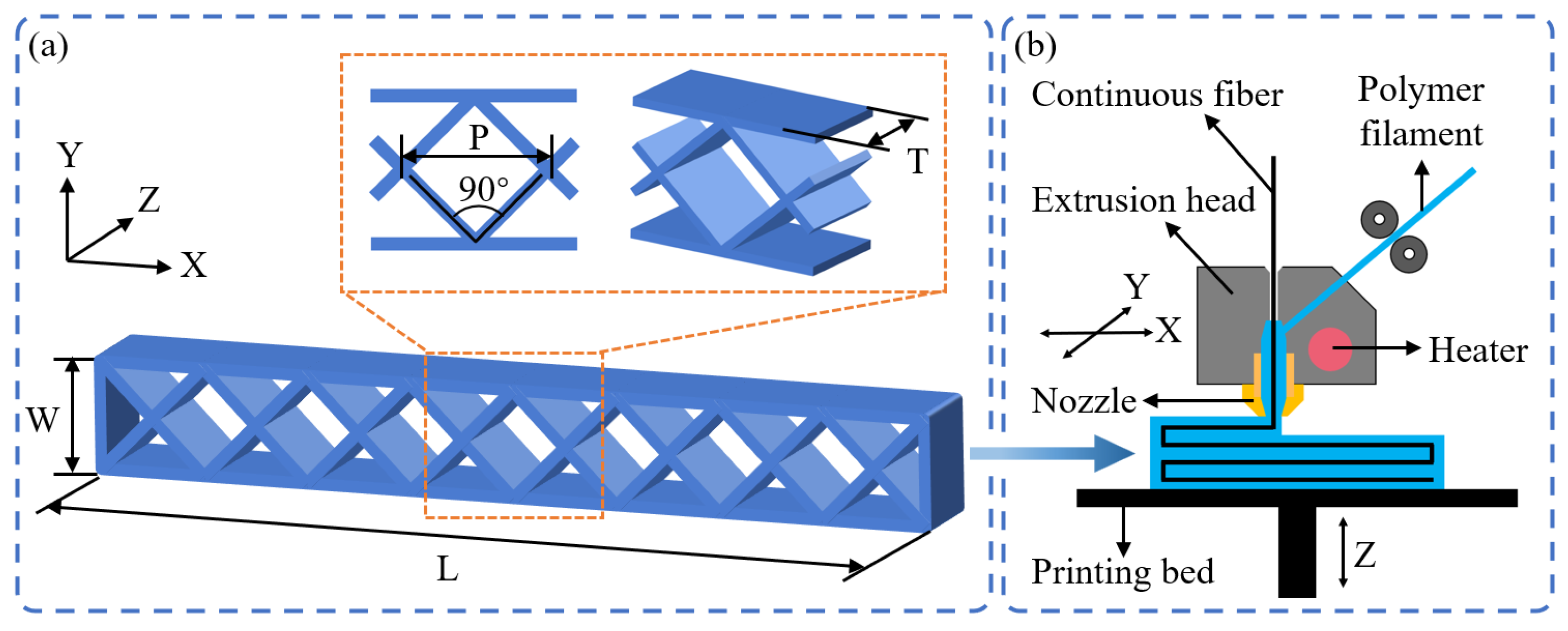
Figure 1. Schematic presentations of (a) the diamond-filled CFRPHSs with geometrical dimensions and (b) 3D printer using the in situ impregnation FDM technique.
Polymers 15 04485 g001
Figure 2. Printing path planning: (a) printing path strategies at the nodes, and (be) four printing paths of the CFRPHSs (the arrows indicate the printing directions, and the colors indicate different printing orders of continuous fibers).
Polymers 15 04485 g002
Figure 3. Schematic diagram of the three-point bending test (the arrow indicates the loading direction).
Polymers 15 04485 g003
Figure 4. Fiber dislocation of the path corners: (a) three path corners in the printing paths: 45°, 90°, and 135°; (b) the printing paths for three path corners; (c) schematic diagram of the evaluation methods; geometric images of three path corners in different L s , (d) L s = 10 mm, (e) L s = 15 mm, and (f) L s = 20 mm.
Polymers 15 04485 g004
Figure 5. The degree of fiber dislocation at the path corners in different L s and α 0 : (a) angle distortion ratio ( φ ) and (b) height distortion ratio ( δ ).
Polymers 15 04485 g005
Figure 6. Schematic diagrams of the fiber dislocation at the path corners: (a) the incompletely solidified matrix could not constrain the CCF effectively; (b) the CCF could not maintain a fixed position relative to the printing nozzle port.
Polymers 15 04485 g006
Figure 7. Photographs of the three-point bending test samples at displacements of (a) 0 mm and (b) 20 mm.
Polymers 15 04485 g007
Figure 8. The bending properties of the CFRPHSs with different printing paths and the PPHS; (a) three-point bending test load-displacement curves; (b) specific load capability and flexural stiffness.
Polymers 15 04485 g008
Figure 9. Fiber distribution modes at the nodes in the loading region of the CFRPHSs with different printing paths: (a) the red node beneath the loading roller; (b) the green node close to the lower face sheet (the red circles indicate the region beneath the loading roller, and the green circles indicate the region close to the lower face sheet).
Polymers 15 04485 g009
Figure 10. Deformation states of the PPHSs at displacements of (a) 6 mm and (b) 18 mm.
Polymers 15 04485 g010
Figure 11. Deformation state I of the CFRPHSs with (a) path A, (b) path B, (c) path C, and (d) path D.
Polymers 15 04485 g011
Figure 12. Deformation state I I of the CFRPHSs with (a) path A, (b) path B, (c) path C, and (d) path D.
Polymers 15 04485 g012
Table 1. Properties of the 3D printing PA filament and CCF.
Filament TypeDensity (g/cm3)Tensile Strength (MPa)Tensile Modulus (GPa)Elongation (%)
PA1.1231.401.05216.50
CCF1.774100.00240.001.70
Table 2. The bending properties of all samples.
PropertiesPath APath BPath CPath DPPHSs
Specific load capability (N/g)63.23 ± 2.5344.12 ± 3.0468.33 ± 2.2560.74 ± 2.8543.48 ± 2.46
Flexural stiffness (N/mm)627.70 ± 33.59696.44 ± 41.28627.70 ± 38.78484.56 ± 35.64183.62 ± 26.57
Disclaimer/Publisher’s Note: The statements, opinions and data contained in all publications are solely those of the individual author(s) and contributor(s) and not of MDPI and/or the editor(s). MDPI and/or the editor(s) disclaim responsibility for any injury to people or property resulting from any ideas, methods, instructions or products referred to in the content.