
Flexible Copper Nanowire/Polyvinylidene Fluoride Membranous Composites with a Frequency-Independent Negative Permittivity


Abstract
:1. Introduction
2. Materials and Methods
2.1. Materials
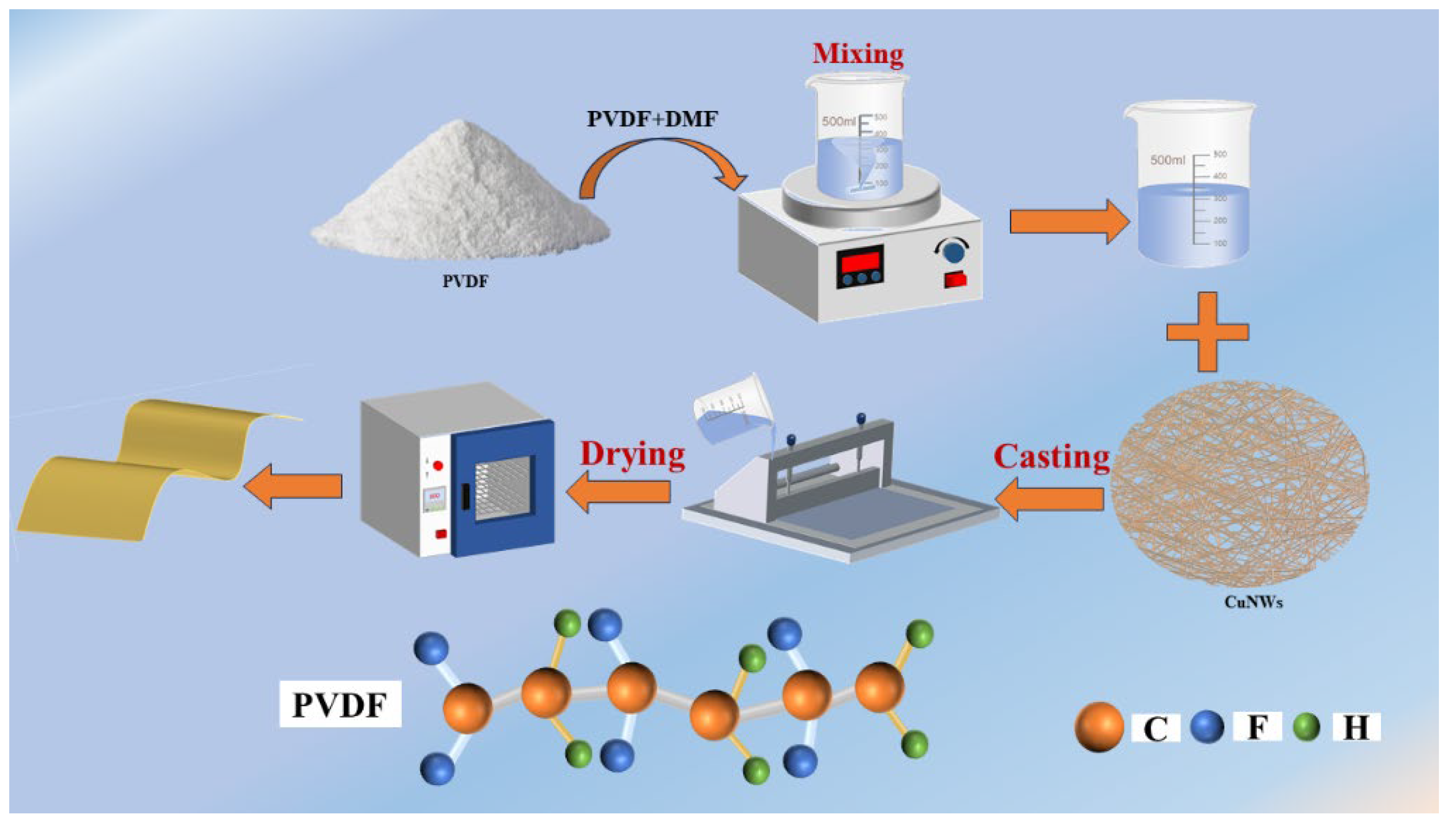
2.2. Methods
2.3. Characterization and Measurement
3. Results and Discussion
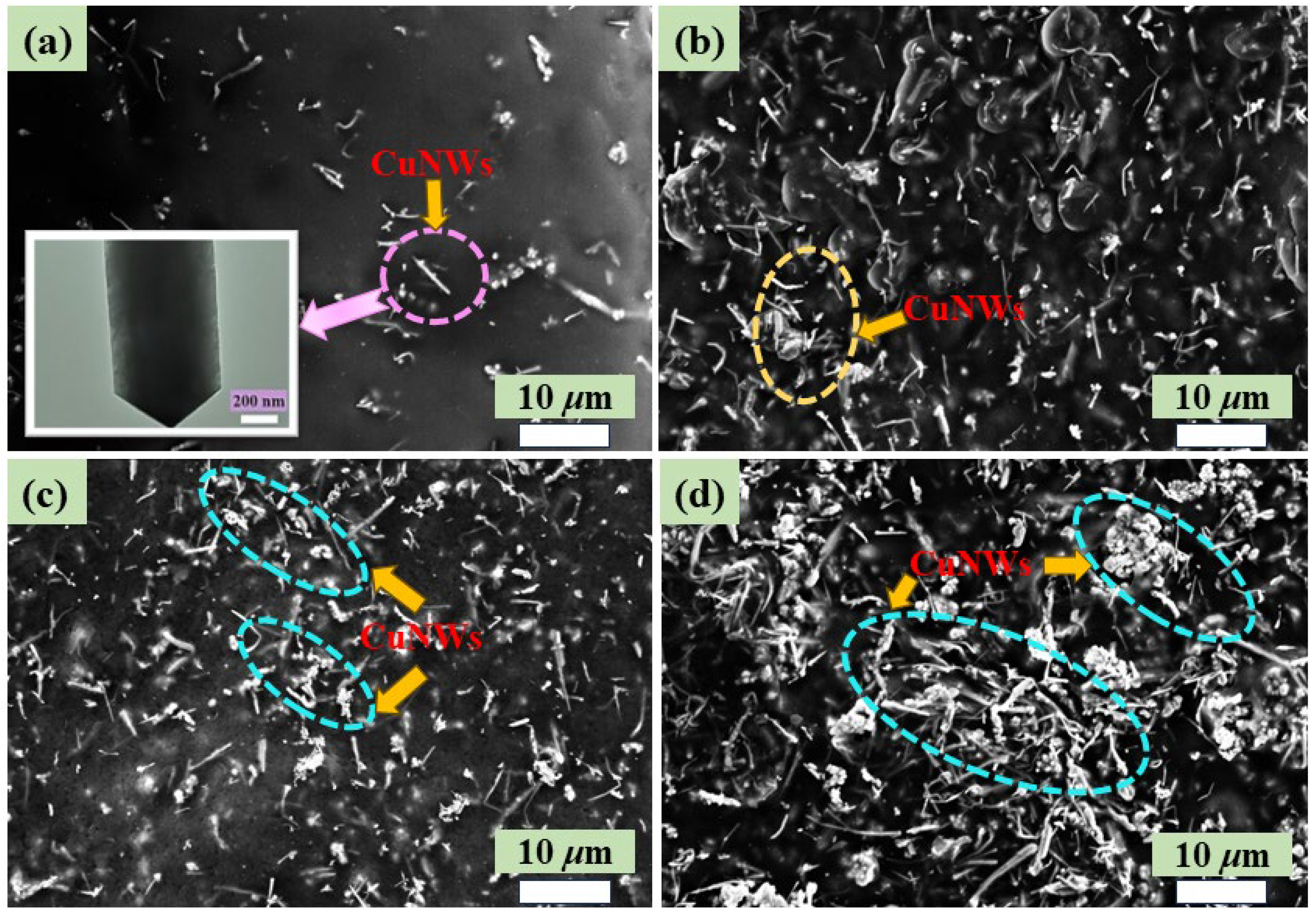
3.1. Microstructural Features and Morphology
3.2. Electrical Conductivity of Alternating Current
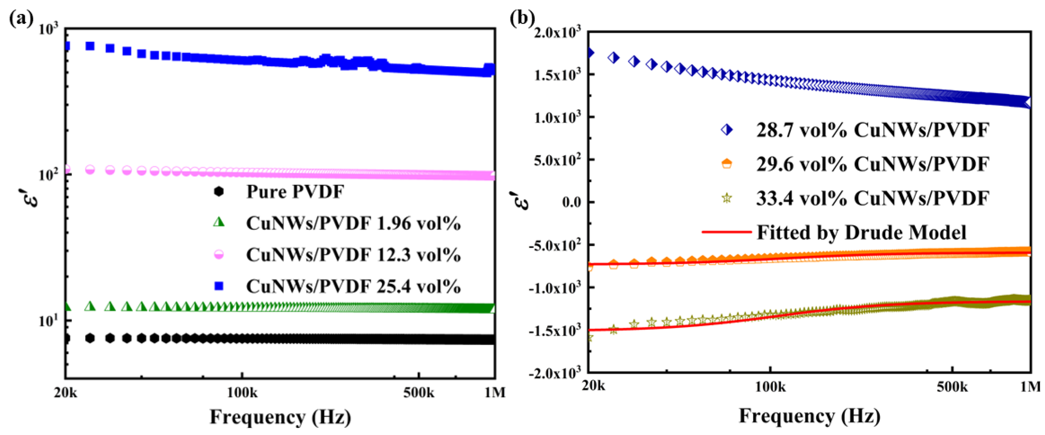
3.3. Dielectric Properties
3.4. Impedance Analysis
4. Conclusions
Author Contributions
Funding
Institutional Review Board Statement
Data Availability Statement
Acknowledgments
Conflicts of Interest
References
- Luo, H.C.; Qiu, J. Carbon nanotubes/epoxy resin metacomposites with adjustable radio-frequency negative permittivity and low dielectric loss. Ceram. Int. 2019, 45, 843–848. [Google Scholar] [CrossRef]
- He, Q.; Sun, K.; Shi, Z.; Liu, Y.; Fan, R. Polymer dielectrics for capacitive energy storage: From theories, materials to industrial capacitors. Mater. Today 2023, 68, 298–333. [Google Scholar] [CrossRef]
- Xu, X.; Fu, Q.; Gu, H.; Guo, Y.; Zhou, H.; Zhang, J.; Pan, D.; Wu, S.; Dong, M.; Guo, Z. Polyaniline crystalline nanostructures dependent negative permittivity metamaterials. Polymer 2020, 188, 122129. [Google Scholar] [CrossRef]
- Xia, S.; Shi, Z.; Sun, K.; Yin, P.; Dastan, D.; Liu, Y.; Cui, H.Z.; Fan, R. Achieving remarkable energy storage enhancement in polymer dielectrics via constructing an ultrathin Coulomb blockade layer of gold nanoparticles. Mater. Horiz. 2023, 10, 2476–2486. [Google Scholar] [CrossRef]
- Sun, K.; Wang, C.; Tian, J.; Zhang, Z.; Zeng, N.; Yin, R.; Duan, W.; Hou, Q.; Zhao, Y.; Wu, H.; et al. Magnetic-driven broadband epsilon-near-zero materials at radio frequency. Adv. Funct. Mater. 2023; Early View. [Google Scholar] [CrossRef]
- Li, B.; Sui, G.; Zhong, W.H. Single negative metamaterials in unstructured polymer nanocomposites toward selectable and controllable negative permittivity. Adv. Mater. 2009, 21, 4176–4180. [Google Scholar] [CrossRef]
- Shen, C.; Hung, T.; Chuang, Y.; Shao, K.; Chi, M. Room-Temperature NH3 gas surface acoustic wave (saw) sensors based on graphene/PPy composite films decorated by Au nanoparticles with ppb detection ability. Polymers 2023, 15, 4353. [Google Scholar] [CrossRef]
- Oganisian, K.; Strek, W. Observation of negative refraction in the graphene/ferrite composite. Phys. Status Solidi Rapid Res. Lett. 2014, 8, 1011–1014. [Google Scholar] [CrossRef]
- Kasagi, T.; Yamamoto, S. Effect of particle shape on electrical conductivity and negative permittivity spectra of Cu granular composite materials. J. Mater. Sci. Mater. Electron. 2022, 33, 4974–4983. [Google Scholar] [CrossRef]
- Tang, X.; Wu, C.; Gan, L.; Zhang, T.; Zhou, T.; Huang, J.; Wang, H.; Xie, C.; Zeng, D. Multilevel microstructured flexible pressure sensors with ultrahigh sensitivity and ultrawide pressure range for versatile electronic skins. Small 2019, 15, 1804559. [Google Scholar] [CrossRef]
- Zhang, Z.; Liu, M.; Ibrahim, M.; Wu, H.; Wu, Y.; Li, Y.; Mersal, G.A.M.; El Azab, I.H.; El-Bahy, S.M.; Huang, M.; et al. Flexible polystyrene/graphene composites with epsilon-near-zero properties. Adv. Compos. Hybrid. Mater. 2022, 5, 1054–1066. [Google Scholar] [CrossRef]
- Zhu, J.; Wei, S.; Ryu, J.; Guo, Z. Strain-sensing elastomer/carbon nanofiber “metacomposites”. J. Phys. Chem. C 2011, 115, 13215–13222. [Google Scholar] [CrossRef]
- Yao, F.; Xie, W.; Yang, M.; Zhang, H.; Gu, H.; Du, A.; Naik, N.; Young, D.; Lin, J.; Guo, Z. Interfacial polymerized copolymers of aniline and phenylenediamine with tunable magnetoresistance and negative permittivity. Mater. Today Phys. 2021, 21, 100502. [Google Scholar] [CrossRef]
- Shi, Y.; Pan, K.; Moloney, M.G.; Qiu, J. Strain sensing metacomposites of polyaniline/silver nanoparticles/carbon foam. Compos. Part. A Appl. Sci. Manuf. 2021, 144, 106351. [Google Scholar] [CrossRef]
- Qin, G.; Qiu, J. Graphene/polypyrrole nanocomposites with high negative permittivity and low dielectric loss tangent. Ceram. Int. 2019, 45, 5407–5412. [Google Scholar] [CrossRef]
- Wan, Y.; Qiu, Z.; Hong, Y.; Wang, Y.; Zhang, J.; Liu, Q.; Wu, Z.; Guo, C.F. A highly sensitive flexible capacitive tactile sensor with sparse and high-aspect-ratio microstructures. Adv. Electron. Mater. 2018, 4, 1700586. [Google Scholar] [CrossRef]
- Wang, H.C.; Mao, P.N.; Lv, H.W.; Peng, H.L. Flexible pulse sensor based on PDMS/MWCNTs. Transducer Microsyst. Technol. 2020, 39, 70–72+76. [Google Scholar] [CrossRef]
- Wang, L.; Jackman, J.A.; Tan, E.L.; Park, J.H.; Potroz, M.G.; Hwang, E.T.; Cho, N.J. High-performance, flexible electronic skin sensor incorporating natural microcapsule actuators. Nano Energy 2017, 36, 38–45. [Google Scholar] [CrossRef]
- Shu, Y.; Tian, H.; Yang, Y.; Li, C.; Cui, Y.; Mi, W.; Li, Y.; Wang, Z.; Deng, N.; Peng, B. Surface-modified piezoresistive nanocomposite flexible pressure sensors with high sensitivity and wide linearity. Nanoscale Microscale Thermophys. Eng. 2015, 7, 8636–8644. [Google Scholar] [CrossRef]
- Leng, Z.; Wu, H.; Tang, X.; Li, Y.; Xin, Y.; Xie, P.; Li, G.; Yan, K.; Liu, C. Carbon nanotube/epoxy composites with low percolation threshold and negative dielectric constant. J. Mater. Sci. Mater. Electron. 2022, 33, 26015–26024. [Google Scholar] [CrossRef]
- Gholipur, R.; Khorshidi, Z.; Bahari, A. Enhanced absorption performance of carbon nanostructure based metamaterials and tuning impedance matching behavior by an external AC electric field. ACS Appl. Mater. Interfaces 2017, 9, 12528–12539. [Google Scholar] [CrossRef] [PubMed]
- Hakim, M.L.; Alam, T.; Soliman, M.S.; Sahar, N.M.; Baharuddin, M.H.; Almalki, S.H.; Islam, M.T. Polarization insensitive symmetrical structured double negative (DNG) metamaterial absorber for Ku-band sensing applications. Sci. Rep. 2022, 12, 479. [Google Scholar] [CrossRef] [PubMed]
- Wang, S.; Luo, Z.; Liang, J.; Hu, J.; Jiang, N.; He, J.; Li, Q. Polymer nanocomposite dielectrics: Understanding the matrix/particle interface. ACS Nano 2022, 16, 13612–13656. [Google Scholar] [CrossRef] [PubMed]
- Mardiansyah, D.; Badloe, T.; Triyana, K.; Mehmood, M.Q.; Raeis-Hosseini, N.; Lee, Y.; Sabarman, H.; Kim, K.; Rho, J. Effect of temperature on the oxidation of Cu nanowires and development of an easy to produce, oxidation−resistant transparent conducting electrode using a PEDOT:PSS coating. Sci. Rep. 2018, 8, 10639. [Google Scholar] [CrossRef]
- Zhang, B.; Li, W.; Yang, Y.; Chen, C.; Li, C.F.; Suganuma, K. Fully embedded CuNWs/PDMS conductor with high oxidation resistance and high conductivity for stretchable electronics. J. Mater. Sci. 2019, 54, 6381–6392. [Google Scholar] [CrossRef]
- Park, J.; Hwang, J.C.; Kim, G.G.; Park, J.U. Flexible electronics based on one-dimensional and two-dimensional hybrid nanomaterials. InfoMat 2020, 2, 33–56. [Google Scholar] [CrossRef]
- Guo, C.; Wang, S.; Wu, C.; Li, L.; Yu, S. Transparent, elastomer-free capacitive pressure sensors using CuNWs and ultrathin UV-cured polymer. Mater. Lett. 2022, 325, 132850. [Google Scholar] [CrossRef]
- Zhao, S.; Han, F.; Li, J.; Meng, X.; Huang, W.; Cao, D.; Zhang, G.; Sun, R.; Wong, C.P. Advancements in copper nanowires: Synthesis, purification, assemblies, surface modification, and applications. Small 2018, 14, 1800047. [Google Scholar] [CrossRef]
- Da Silva, A.B.; Arjmand, M.; Sundararaj, U.; Bretas, R.E.S. Novel composites of copper nanowire/PVDF with superior dielectric properties. Polymer 2014, 55, 226–234. [Google Scholar] [CrossRef]
- Yu, S.H.; Li, J.J.; Zhao, L.; Wang, B.; Zheng, H.R. Stretch-insensitive capacitive pressure sensor based on highly stretchable CuNWs electrode. Sens. Actuator A Phys. 2022, 346, 113868. [Google Scholar] [CrossRef]
- Zhou, Y.; Zaghloul, M. Changes in permittivity of the piezoelectric material PVDF as functions of the electrical field and temperature. Materials 2021, 14, 5736. [Google Scholar] [CrossRef] [PubMed]
- Yang, Y.; Chen, J.; Li, Y.; Shi, D.; Lin, B.; Zhang, S.; Tang, Y.; He, F.; Lam, K. Preparation and dielectric properties of composites based on PVDF and PVDF-grafted graphene obtained from electrospinning-hot pressing method. J. Macromol. Sci. A 2018, 55, 148–153. [Google Scholar] [CrossRef]
- Qi, F.; Xu, L.; He, Y.; Yan, H.; Liu, H. PVDF-based flexible piezoelectric tactile sensors: Review. Cryst. Res. Technol. 2023, 58, 2300119. [Google Scholar] [CrossRef]
- Engheta, N. 150 years of Maxwell’s equations. Science 2015, 349, 136–137. [Google Scholar] [CrossRef]
- Gu, H.; Guo, J.; Khan, M.; Young, D.; Shen, T.; Wei, S.; Guo, Z. Magnetoresistive polyaniline–silicon carbide metacomposites: Plasma frequency determination and high magnetic field sensitivity. Phys. Chem. Chem. Phys. 2016, 18, 19536–19543. [Google Scholar] [CrossRef] [PubMed]
- Mantas, P. Dielectric response of materials: Extension to the Debye model. J. Eur. Ceram. Soc. 1999, 19, 2079–2086. [Google Scholar] [CrossRef]
- Sun, K.; Wang, Z.; Xin, J.; Wang, Z.; Xie, P.; Fan, G.; Murugadoss, V.; Fan, R.; Fan, J.; Guo, Z. Hydrosoluble graphene/polyvinyl alcohol membranous composites with negative permittivity behavior. Macromol. Mater. Eng. 2020, 305, 1900709. [Google Scholar] [CrossRef]
- Sun, K.; Dong, J.; Wang, Z.; Wang, Z.; Fan, G.; Hou, Q.; An, L.; Dong, M.; Fan, R.; Guo, Z. Tunable negative permittivity in flexible graphene/PDMS metacomposites. J. Phys. Chem. C 2019, 123, 23635–23642. [Google Scholar] [CrossRef]
- Xu, C.; Fan, G.; Qu, Y.; Liu, Y.; Zhang, Z.; Fan, R. Core-shell structured tungsten carbide/polypyrrole metacomposites with tailorable negative permittivity at the radio frequency. Polymer 2020, 188, 122125. [Google Scholar] [CrossRef]
- Tang, X.; Zhang, Z.; Zheng, K.; Wu, Y.; Chen, Z.; Wang, C.; Shi, Z. Low dielectric loss in poly (vinyl alcohol)/graphene metacomposite films with negative permittivity prepared by spin coating. Polymer 2023, 281, 126092. [Google Scholar] [CrossRef]
- Sun, Z.; Yan, Z.; Yin, R.; Huang, X.; Yue, K.; Li, A.; Qian, L. Homogeneous poly (vinylidenefluoride)-graphene films with secondary percolation behaviors towards negative permittivity properties. Compos. Commun. 2020, 17, 18–21. [Google Scholar] [CrossRef]
- Swetha, P.; Aswini, R.; Binesh, M.; Th, M.S.; Sridharan, K.; Swaminathan, S. Cost efficient fabrication of flexible polymer metacomposites: Impact of carbon in achieving tunable negative permittivity at low radio frequency range. Mater. Today Commun. 2023, 34, 105287. [Google Scholar] [CrossRef]
- Shetty, H.D.; Prasad, V. Existence of negative permittivity in carbon coated iron nanoparticle—PDMS composites. Mater. Chem. Phys. 2017, 196, 153–159. [Google Scholar] [CrossRef]
- Iç, S.; Kalkan, N.; Karabul, Y.; Özdemir, Z.; Kiliç, M. Analyses of negative real permittivity behavior, AC conductivity and impedance properties of (YxEu1−x)Ba2Cu3O6.5 ceramics. Ceram. Int. 2023, 49, 23546–23557. [Google Scholar] [CrossRef]


| Composites Category | Fillers Content | Dispersion (Beginning–End) | Frequency Range | References |
|---|---|---|---|---|
| GR/PVA | 26% | −5.5 × 10⁴ to −3.0 × 10⁴ | 10 kHz–1 MHz | [37] |
| GR/PDMS | 4% | −6.1 × 10⁴ to −3.0 × 10⁴ | 10 kHz–1 MHz | [38] |
| WC/PPy | 60% | −3.0 × 10³ to −300 | 10 kHz–1 MHz | [39] |
| PVA/GR | 20% | −4.8 × 10³ to −480 | 10 kHz–1 MHz | [40] |
| PVP@GR/PVDF | 25% | −480 to −50 | 10 MHz–1 GHz | [41] |
| PVA/CB | 2.5% | −450 to 0 | 10 kHz–10 MHz | [42] |
| PDMS/CCFeNP | 50% | −4 × 10³ to −400 | 100 Hz–100 MHz | [43] |
| CuNW/PVDF | 29.6% | −760 to −584 | 20 kHz–1 MHz | This work |
Disclaimer/Publisher’s Note: The statements, opinions and data contained in all publications are solely those of the individual author(s) and contributor(s) and not of MDPI and/or the editor(s). MDPI and/or the editor(s) disclaim responsibility for any injury to people or property resulting from any ideas, methods, instructions or products referred to in the content. |
© 2023 by the authors. Licensee MDPI, Basel, Switzerland. This article is an open access article distributed under the terms and conditions of the Creative Commons Attribution (CC BY) license (https://creativecommons.org/licenses/by/4.0/).
Share and Cite
Sun, K.; Ma, A.; Yang, P.; Qi, J.; Lei, Y.; Zhang, F.; Duan, W.; Fan, R. Flexible Copper Nanowire/Polyvinylidene Fluoride Membranous Composites with a Frequency-Independent Negative Permittivity. Polymers 2023, 15, 4486. https://doi.org/10.3390/polym15234486
Sun K, Ma A, Yang P, Qi J, Lei Y, Zhang F, Duan W, Fan R. Flexible Copper Nanowire/Polyvinylidene Fluoride Membranous Composites with a Frequency-Independent Negative Permittivity. Polymers. 2023; 15(23):4486. https://doi.org/10.3390/polym15234486
Chicago/Turabian StyleSun, Kai, Ao Ma, Pengtao Yang, Jinjiu Qi, Yanhua Lei, Fei Zhang, Wenxin Duan, and Runhua Fan. 2023. "Flexible Copper Nanowire/Polyvinylidene Fluoride Membranous Composites with a Frequency-Independent Negative Permittivity" Polymers 15, no. 23: 4486. https://doi.org/10.3390/polym15234486
APA StyleSun, K., Ma, A., Yang, P., Qi, J., Lei, Y., Zhang, F., Duan, W., & Fan, R. (2023). Flexible Copper Nanowire/Polyvinylidene Fluoride Membranous Composites with a Frequency-Independent Negative Permittivity. Polymers, 15(23), 4486. https://doi.org/10.3390/polym15234486