Article

Introduction of Nanoscale Si3N4 to Improve the Dielectric Thermal Stability of a Si3N4/P(VDF-HFP) Composite Film

Science and Technology on Thermostructural Composite Materials Laboratory, Northwestern Polytechnical University, Xi’an 710072, China
*
Author to whom correspondence should be addressed.
Polymers 2023, 15(21), 4264; https://doi.org/10.3390/polym15214264
Submission received: 7 September 2023 / Revised: 8 October 2023 / Accepted: 18 October 2023 / Published: 30 October 2023
(This article belongs to the Section Polymer Membranes and Films)

Abstract

:
In order to improve the dielectric thermal stability of polyvinylidene fluoride (PVDF)-based film, nano silicon nitride (Si3N4) was introduced, and hence the energy storage performance was improved. The introduction of nano Si3N4 fillers will induce a phase transition of P(VDF-HFP) from polar β to nonpolar α, which leads to the improved energy storage property. As such, the discharging energy density of Si3N4/P(VDF-HFP) composite films increased with the amount of doped Si3N4. After incorporating 10wt% Si3N4 in Si3N4/P(VDF-HFP) films, the discharging density increased to 1.2 J/cm3 under a relatively low electric field of 100 MV/m. Compared with a pure P(VDF-HFP) film, both the discharging energy density and thermal dielectric relaxor temperature of Si3N4/P(VDF-HFP) increased. The working temperature increased from 80 °C to 120 °C, which is significant for ensuring its adaptability in high-temperature energy storage areas. Thus, this result indicates that Si3N4 is a key filler that can improve the thermal stability of PVDF-based energy storage polymer films and may provide a reference for high-temperature capacitor materials.

1. Introduction

The advanced electronic and electrical industry requires energy storge capacitors possessing the characteristics of miniaturization, easy portability, good stability, and so on [1,2]. Thus, as a key component of capacitors, dielectric materials must be lightweight, flexible, and have a high energy storage density [3]. After decades of efforts, the traditional inorganic dielectric materials, such as barium strontium (BaTiO3)-series ceramics, calcium copper titanate (CCTO), and lead zirconate titanate (PZT), have been well investigated and widely used as capacitors in some areas [4]. These dielectric ceramics show the characteristics of a large Young’s modulus, a high dielectric constant (εr), and low dielectric loss (tan δ), but they have a low energy density and weak tolerance for changing electric fields, and additionally, these ceramics are hard, brittle, and difficult to process into specially shaped units [5]. More significantly, this ceramic material is unable to meet the requirements of small size, high flexibility, and portability in a high-power-density capacitor. In contrast, dielectric polymers are light, easy to process, and show considerable electrical resistance (>500 MV/m), which is believed to make up for the disadvantages of ceramics [6].
The energy density, Ue, of dielectric materials is an important parameter to evaluate when assessing energy storage capacity. To improve the energy density of polymers, Qiming Zhang et al., in 2006 [7], proposed that the oriented polyvinylidene fluoride trifluorochloroethylene (P(VDF-CTFE) can be employed for energy storage, as it has a large electric dipole moment (-CF2-CH2-) and produces a huge electrical displacement (D) (about 0.13 μC/cm2) in P(VDF-CTFE [8]. After stretching, the εr of P (VDF-CTFE) is about 12, Eb is as high as 700 MV/m, and Ue reaches 21 J/cm3 at the maximum polarization electric field, which is far higher than that of BOPP [9]. As is already known, PVDF-based polymers are nonlinear dielectrics, and Ue is usually calculated from formula [10]
U e = E   d D
Thus, besides displacement, using polymer materials with an Eb larger than 500 MV/m is essential for achieving a high capacitor Ue. However, for nonlinear PVDF-based polymers, working at such a high electrical field while maintaining good stability is difficult [11]. More importantly, PVDF-based polymers have poor thermal conductivity, and multiple charging and discharging processes at high-frequency electrical fields will generate a lot of heat, resulting in an increase in the temperature of the capacitor and further leading to the thermal aging of the polymer materials or even the destruction of related capacitors [12].
To solve this problem, many researchers have proposed introducing ceramic particles, such as BaTiO3, PZT, copper calcium titanate (CCTO), etc., as fillers into PVDF-based polymers to construct a polymer/ceramic composite [13,14,15]. One of the purposes of this design is to improve the electrical displacement and dielectric properties by virtue of the high ion displacement of these ceramics. Another reason for choosing this design is to reduce the working electrical field of dielectric polymers. For example, recently, an energy density of 10.54 J/cm3 was obtained in a Ba0.6Sr0.4TiO3/PVDF composite thin film under 300 MV/m, which is larger than that of pure PVDF [16]. And a K0.5Na0.5NbO3-SrTiO3/PVDF polymer composite film was prepared with a recoverable energy storage density of 1.34 J/cm3 under 100 MV/m [17]. Moreover, BaTiO3-doped PVDF composites with a well-treated interface exhibit a maximum energy storage density of 4.08 J/cm3 under 200 MV/m [18]. In the above research, although the Ue under a low electrical field was improved, the heat generated from frequent charging–discharging processes still posed a big problem to the use of these materials in capacitors. This is because most ceramic fillers have poor thermal conductivity [19,20].
For this reason, researchers recently proposed doping PVDF-based polymers with ceramics with high thermal conductivity, and the fillers used were mainly SiC-series inorganic particles [21,22,23]. The introduction of fillers with high thermal conductivity, to a certain degree, solved the problem of the poor thermal conductivity of composite materials. However, SiC-series inorganic particles are also good electric conductors, which can lead to considerable energy loss in PVDF-based composites. Thus, how to improve the thermal stability while maintaining an improved Ue and low loss should be further investigated [24].
Thus, in this work, we selected the relaxor ferroelectric copolymer of polyvinylidene fluoride hexafluoropropylene (P(VDF-HFP)) as the polymer matrix, as it proved in our former report [25] to possess a favorable energy storage performance. In addition, nano-sized Si3N4 was used as a replacement for SiC-series fillers. We expected to achieve a relatively high discharging energy density with good thermal stability for this Si3N4/P(VDF-HFP) two-phase composite film.

2. Materials and Methods

Silicon nitride (Si3N4) with a size ranging from 100 nm to 200 nm was obtained from Suzhou Yuante Material Co., Ltd. (Suzhou, China), and was further purified using analytic reagent ethyl alcohol. P(VDF-HFP) powder with a 91/9 mol% VDF/HFP ratio was purchased from Piezotech Co. (Pierre-Bénite, France). Si3N4/P(VDF-HFP) composite films were prepared using the solution casting method, as shown in Figure 1. P(VDF-HFP) was dissolved in dimethyl formamide (DMF) and then purified using the filter element. After that, purified Si3N4 nanoparticles were introduced into the solutions of P(VDF-HFP) with various mass fractions of 0 wt%, 5 wt%, 7.5 wt%, 10 wt%, 12.5 wt%, 15 wt%, 17.5 wt%, 20 wt%, and 22.5 wt%. After stirring for 12 h, the uniform solution was coated on the glass slides at room temperature in the oven for the drying process. Then, the solvent was evaporated at 70 °C for 12 h, and in order to remove the DMF solvent completely, the dried Si3N4/P(VDF-HFP) composite film was melted by holding it at 170 °C for 6 h. To modify the crystalline properties of P(VDF-HFP) [26], the hot Si3N4/P(VDF-HFP) melt was cooled rapidly to room temperature in air, and similar Si3N4/P(VDF-HFP) composite films with different Si3N4 fractions and a relatively uniform thickness of 30 μm were obtained. For electrical characterization, the different films were cut into the desired dimensions and gold electrodes 80 nm in thickness were sputtered on both sides of the film as the top and bottom electrodes.
The crystal phases of Si3N4/P(VDF-HFP) composite films were examined using X-ray diffraction (XRD) with a RIGAKU D/MAX-2400 diffractometer (Akishima, Japan) with a scanning rate of 20°/min, and the wavelength of the X-ray was 1.542 Å (Cu Ka radiation, 40 kV and 100 mA). A Shimadzu Fourier 8400S spectrometer (Kyoto, Japan) was employed to scan the Fourier transform infrared (FTIR) spectra of samples in the wavelength range of 400–1500 cm−1 with a resolution of 0.85 cm−1. SEM Quanta F250 (Oberkochen, Germany) with an energy-dispersive X-ray spectroscopy (EDS) detector was used to determine the morphology of the composite films. The dielectric frequency and thermal properties were measured using an Agilent-4284A (Lake Mary, FL, USA) precision impedance analysis LCR tester in the frequency range of 100 Hz–10 MHz. A TF Analyzer 2000 ferroelectric test system (Aachen, Germany) was employed to obtain the displacement vs. electric field unipolar hysteresis (D-E) curves with a triangular voltage wave form at a frequency of 10 Hz.

3. Results and Discussion

In order to investigate the influence of the introduction of Si3N4 into the crystal structure of P(VDF-HFP), Figure 2 shows the XRD diagram of Si3N4/P(VDF-HFP) composite film samples doped with different amounts of Si3N4. The pure P(VDF-HFP) film exhibited obvious characteristic diffraction peaks at 18.5° and 20.2°, corresponding to the (020) and (110/002) crystal planes, respectively [24]. Regarding these, (020) is the typical characteristic peak of the α-crystal phase, and (110/002) are the typical characteristic peaks of the β-crystal phase. Compared with the pure P(VDF-HFP) film, the XRD of the composite film samples doped with Si3N4 exhibited not only diffraction peaks of the polymer matrix but also the peaks of Si3N4 at the positions 13.3°, 20.6°, 22.9°, 26.5°, 31.1°, 34.5°, 35.3°, 38.1°, 38.3°, 41.9°, and 43.5°, corresponding to (010), (101), (110), (220), (201), (102), (210), (211), (112), (021), (310), and other crystal planes. Moreover, Figure 2b provides the refined result of the XRD patterns of Si3N4 particles, indicating the existence of the α-crystal phase in the Si3N4 sample obtained, and the pattern matches the standard card peak of slice PDF# 41-0360 [27]. The successful recombination of P(VDF-HFP) and Si3N4 is shown, and the characteristic diffraction peak intensity of Si3N4 was seen to gradually increase with the increase in Si3N4 content.
In addition, as the content of Si3N4 increased, the characteristic diffraction peak of the sample (110/002), corresponding to peak 20.6°, shifted to about ~20.0°. According to the Bragg formula, the increasing crystal plane spacing of the sample indicates that the addition of Si3N4 had an influence on the crystal form of P(VDF-HFP) film. Although it showed a slight change, the peak shift from plane (110/002) to plane (110) of P(VDF-HFP) corresponds to the phase transition from β to α(γ) due to the presence of Si3N4 filler. This is because the ~20.0° peak refers to the diffraction position of the α- or γ-crystal phase, according to the literature. [28] Compared with highly polar β-P(VDF-HFP), whose remnant polarization is so high that the dipoles cannot reverse with frequent electric fields, non-α-P(VDF-HFP) is more suitable as a material for high-frequency charging–discharging capacitors [29].
To further investigate and verify the crystal structure of Si3N4/P(VDF-HFP) composite films, FTIR was used to analyze the crystal structure of composite film samples with different Si3N4 contents, as shown in Figure 3. Clearly, the absorption peaks of the α phase, β phase, and γ phase appeared in all the thin-film samples. The six absorption peaks that appeared at 484 cm−1, 615 cm−1, 759 cm−1, 1068 cm−1, 1169 cm−1, and 1401 cm−1 corresponded to the α phase (TGTG conformation of -CF2-CH2- chains); the absorption peak at 873 cm−1 corresponded to the β phase (TTTT); and the absorption peak at 832 cm−1 corresponded to the γ phase (TGTG’) [30]. Among these absorption peaks, with the addition of Si3N4, the absorption peak intensity at 873 cm−1 of the β phase weakened, indicating that all the trans β-crystal phases decreased with the introduction of Si3N4 particles. Moreover, with the introduction of Si3N4, the absorption peak intensity of the α phase slightly increased, and the absorption peak at 832 cm−1 of the γ phase disappeared. This was due to the occurrence of the phase transition from the γ phase to the α phase. Additionally, importantly, the crystallinity of P(VDF-HFP) was slightly depressed by the introduction of Si3N4, and the FTIR results are consistent with the XRD results. This phase transition promotes the dielectric and energy storage properties of this kind of two-phase composite.
Figure 4a–i show the cross-sectional SEM images of Si3N4/P(VDF-HFP) composites with different Si3N4 doping contents, indicating that the P(VDF-HFP) matrix was successfully doped with Si3N4 nanoparticles. As the doping amount of Si3N4 increased, an increasing amount Si3N4 was observed in the polymer matrix. However, when the doping amount of Si3N4 was too high, an obvious agglomeration phenomenon appeared in some areas of the composite films, such as that seen with a doping amount of 20 wt% Si3N4, as shown in Figure 4h. In order to further verify the composite composition between the filler and the matrix, EDS detection was performed on pure P(VDF-HFP) and the composite film sample with a Si3N4 content of 22.5 wt%, as shown in Figure 3j,k. In Figure 4j, the peak positions and percentage contents of the C and F elements (H element has no inner electrons and cannot be determined) in pure P(VDF-HFP) can be clearly seen. In Figure 4k, the peak positions and percentage contents of the C and F elements in pure P(VDF-HFP) and the Si and N elements in Si3N4 can be observed, which further confirms the successful development of a composite of the filler and the matrix.
To clarify the effect of Si3N4 on the electric properties of P(VDF-HFP)-based composite films, Figure 5a,b present the variation trend of the relative dielectric constant (εr) and dielectric loss (tanδ) of different Si3N4/P(VDF-HFP) composite film samples with frequency and Si3N4 content. Firstly, it can be seen from Figure 5a that εr decreased with increasing frequency. According to the theory of polarization, when the frequency of the AC electric field is small, various polarization modes, such as electron polarization, atomic polarization, dipole orientation polarization, and interface polarization of the dielectric material, will contribute to εr. Therefore, εr is relatively high at low frequencies. As the frequency increases, the dipole orientation polarization cannot keep up with the rate of change in frequency, making it unable to play its great role, resulting in the decrease in εr. As the frequency further increases and the dipole orientation polarization is further weakened, εr is greatly reduced at high frequencies. In addition, with the increase in Si3N4 content, the Si3N4/P(VDF-HFP) composite films’ εr was enhanced to a certain extent: the value of the 10wt% Si3N4 reached 14 at 100 Hz, which is 33.3% higher than that of pure P(VDF-HFP) (~10.5). The reason for the enhancement of εr is that the appropriate addition of Si3N4 increases interface polarization and ion polarization.
Moreover, variation in the tan δ of all Si3N4/P(VDF-HFP) composite film samples followed a trend of first decreasing and then increasing with the increase in frequency. In the low-frequency range, the tan δ of composite materials mainly depends on conductivity loss, which decreases with increasing frequency. In the high-frequency range, the tan δ of composite materials mainly depends on polarization loss, which increases with increasing frequency. In addition, the tan δ of Si3N4/P(VDF-HFP) composite material increases as the content of Si3N4 increases, as shown in Figure 5b, and this is because higher amounts of Si3N4 result in agglomerated defects in the P(VDF-HFP) matrix, leading to an increase in the heterogeneity of the composite material and a higher tanδ than that of pure polymers [28,31].
In order to further investigate the influence of Si3N4 content on the dielectric thermal stability of Si3N4/P(VDF-HFP) composites, we determined the dielectric temperature spectrum of different samples tested at a frequency ranging from −20 °C to 150 °C, as shown in Figure 6. In pure P(VDF-HFP), the εr curve had no obvious peak (Figure 6a), and the wide dielectric peak corresponded to the dielectric relaxation generated by dipole polarization with increasing temperature. This is because the crystallization zone of pure P(VDF-HFP) is mainly a nonpolar α phase and a few polar β phases. After the appropriate addition of Si3N4, the dielectric peak became weaker as a result of the reduction in the β-phase proportion, as proved by the XRD and FTIR results. Nevertheless, the dielectric temperature spectrum curve exhibits a dielectric peak at approximately 75 °C, which was attributed to the dielectric temperature relaxation of nonlinear PVDF-based copolymers, as shown in Figure 6b–h, instead of the F-P phase transition. In addition, the εr of all film samples decreased with increasing frequency, which is consistent with the dielectric frequency spectrum.
In practical applications, the temperature stability of Si3N4/P(VDF-HFP) composite material as a functional capacitor also deserves special attention. To evaluate the dielectric temperature stability of Si3N4/P(VDF-HFP) composites, Figure 6i summarizes the dielectric temperature spectrum of all Si3N4/P(VDF-HFP) composites at a frequency of 1 kHz. As the temperature increased, the εr curves of all samples showed a trend almost parallel to the abscissa, indicating that the Si3N4/P(VDF-HFP) composite material samples had good temperature stability. The reason for this is that Si3N4/is a good conductor of heat, being able to significantly absorb the heat from the composites and improve the thermal stability and dielectric properties of Si3N4/P(VDF-HFP). As such, Si3N4/P(VDF-HFP) with a high Si3N4 content of 20wt% possessed a gentler dielectric curve than other samples, as indicated in Figure 6i. Attractively, compared with pure P(VDF-HFP), the thermal relaxor temperature of the Si3N4/P(VDF-HFP) exhibiting dielectric loss increased from 80 °C to 120 °C, which is significant for high-temperature energy storage areas.
In addition, Figure 7a–g show the unipolar hysteresis loops of all Si3N4/P(VDF-HFP) composite film samples at a frequency of 10 Hz under an increasing electrical field. Clearly, the maximum polarization (Pm) and residual polarization (Pr) of all samples gradually increased with the increase in the electric field. This is because a large electric field can cause large orientation polarization in a material. As the content of Si3N4 increased, Pm and Pr first increased and then decreased. The main reason for this is that an appropriate amount of Si3N4 can increase interface polarization and ion polarization. However, excessive Si3N4 will cause more defects in the material, leading to an unpleasant current leakage. In order to determine the energy storage performance of Si3N4/P(VDF-HFP), composite film samples were prepared by the institute as raw materials for capacitors, and the formula [8]
W r e c = P r P m a x E   d P
was used to calculate the recoverable energy density (Wrec) of all samples. Here, E is the electric field and P is the polarization intensity. According to the formula, a large polarization difference (Pm-Pr) is the key to obtaining a large Wrec. Table 1 lists the Pm, Pr, and Pm-Pr of Si3N4/P(VDF-HFP) composite film samples.
Figure 7h shows the Wrec of all Si3N4/P(VDF-HFP) composite film samples with different Si3N4 contents. As seen in Figure 7h, Wrec first increased and then decreased with the increase in Si3N4 content, and it reached 1.2 J/cm3 when the content of Si3N4 increased to 10 wt%. The reason for this increase is that the addition of an appropriate amount of Si3N4 increased Pm-Pr, resulting in an increase in the calculated Wrec. Then, Wrec decreased as more Si3N4 was added. The reason for this is that excess Si3N4 may lead to the current leakage and has a negative influence on the discharging energy density.

4. Conclusions

In this work, Si3N4/P(VDF-HFP) composite film samples were prepared using the solution casting method. The crystal structure, microstructure, dielectric property, temperature stability, and energy storage performance of the Si3N4/P(VDF-HFP) composite materials were characterized and tested. Through characterization methods such as XRD, FTIR, and SEM, it was found that a P(VDF-HFP) matrix with Si3N4 filler was successfully composed. Through analyzing the dielectric temperature spectrum, it was found that the appropriate addition of Si3N4 increased the ferroelectric phase of the P(VDF-HFP) polymer matrix, and the dielectric properties of the sample exhibited good temperature stability from −20 to 150 °C. In addition, the Wrec of the composite film sample was obtained by calculating the unipolar hysteresis loops, and it was found that the appropriate addition of Si3N4 contributed to the improvement in energy storage performance. Therefore, the Si3N4/P(VDF-HFP) composite material proposed in this work can be applied to capacitor devices operating under high-temperature conditions.

Author Contributions

J.G. mainly contributed to the conception of this study, carrying out measurements, and manuscript composition. Y.F. mainly contributed to the conception of the experimental design and funding. L.C. contributed to the funding and manuscript composition. All authors have read and agreed to the published version of the manuscript.

Funding

This work was supported by the ND Basic Research Funds (G2023WD).

Institutional Review Board Statement

Not applicable.

Data Availability Statement

Data available on request.

Acknowledgments

Many thanks to my supervisors, Laifei Cheng and Ye Fang, for their guidance during this research.

Conflicts of Interest

The authors declare no conflict of interest.

References

  1. Fan, B.; Zhou, M.; Zhang, C.; He, D.; Bai, J. Polymer-based materials for achieving high energy density film capacitors. Prog. Polym. Sci. 2019, 97, 101143. [Google Scholar] [CrossRef]
  2. Tan, D.Q. Review of Polymer-Based Nanodielectric Exploration and Film Scale-Up for Advanced Capacitors. Adv. Funct. Mater. 2019, 30, 1808567. [Google Scholar] [CrossRef]
  3. Zhang, G.; Li, Q.; Allahyarov, E.; Li, Y.; Zhu, L. Challenges and Opportunities of Polymer Nanodielectrics for Capacitive Energy Storage. ACS Appl. Mater. Interfaces 2021, 13, 37939–37960. [Google Scholar] [CrossRef]
  4. Li, D.; Zeng, X.; Li, Z.; Shen, Z.-Y.; Hao, H.; Luo, W.; Wang, X.; Song, F.; Wang, Z.; Li, Y. Progress and perspectives in dielectric energy storage ceramics. J. Adv. Ceram. 2021, 10, 675–703. [Google Scholar] [CrossRef]
  5. Burn, I.; Smyth, D.M. Energy storage in ceramic dielectrics. J. Mater. Sci. 1972, 7, 339–343. [Google Scholar] [CrossRef]
  6. Luo, H.; Wang, F.; Guo, R.; Zhang, D.; He, G.; Chen, S.; Wang, Q. Progress on Polymer Dielectrics for Electrostatic Capacitors Application. Adv. Sci. 2022, 9, e2202438. [Google Scholar] [CrossRef] [PubMed]
  7. Chu, B.; Zhou, X.; Ren, K.; Neese, B.; Lin, M.; Wang, Q.; Bauer, F.; Zhang, Q.M. A Dielectric Polymer with High Electric Energy Density and Fast Discharge Speed. Science 2006, 313, 334–336. [Google Scholar] [CrossRef]
  8. Lovinger, A.J.J.S. Ferroelectric Polymers. Science 1983, 220, 1115–1121. [Google Scholar] [CrossRef] [PubMed]
  9. Ritamaki, M.; Rytoluoto, I.; Lahti, K. Performance metrics for a modern BOPP capacitor film. IEEE Trans. Dielectr. Electr. Insul. 2019, 26, 1229–1237. [Google Scholar] [CrossRef]
  10. Rožič, B.; Malič, B.; Uršič, H.; Holc, J.; Kosec, M.; Neese, B.; Zhang, Q.M.; Kutnjak, Z. Direct Measurements of the Giant Electrocaloric Effect in Soft and Solid Ferroelectric Materials. Ferroelectrics 2010, 405, 26–31. [Google Scholar] [CrossRef]
  11. Marshall, J.E.; Zhenova, A.; Roberts, S.; Petchey, T.; Zhu, P.; Dancer, C.E.J.; McElroy, C.R.; Kendrick, E.; Goodship, V. On the Solubility and Stability of Polyvinylidene Fluoride. Polymers 2021, 13, 1354. [Google Scholar] [CrossRef]
  12. Ho, J.S.; Greenbaum, S.G. Polymer Capacitor Dielectrics for High Temperature Applications. ACS Appl. Mater. Interfaces 2018, 10, 29189–29218. [Google Scholar] [CrossRef]
  13. Liu, S.; Xue, S.; Zhang, W.; Zhai, J.; Chen, G. The influence of crystalline transformation of Ba0.6Sr0.4TiO3 nanofibers/poly(vinylidene fluoride) composites on the energy storage properties by quenched technique. Ceram. Int. 2015, 41, S430–S434. [Google Scholar] [CrossRef]
  14. Xia, W.; Xu, Z.; Wen, F.; Zhang, Z. Electrical energy density and dielectric properties of poly(vinylidene fluoride-chlorotrifluoroethylene)/BaSrTiO3 nanocomposites. Ceram. Int. 2012, 38, 1071–1075. [Google Scholar] [CrossRef]
  15. Thomas, P.; Varughese, K.T.; Dwarakanath, K.; Varma, K.B.R. Dielectric properties of Poly(vinylidene fluoride)/CaCu3Ti4O12 composites. Compos. Sci. Technol. 2010, 70, 539–545. [Google Scholar] [CrossRef]
  16. Guo, Y.; Wu, S.; Liu, S.; Xu, J.; Pawlikowska, E.; Szafran, M.; Rydosz, A.; Gao, F. Enhanced dielectric tunability and energy storage density of sandwich-structured Ba0.6Sr0.4TiO3/PVDF composites. Mater. Lett. 2022, 306, 130910. [Google Scholar] [CrossRef]
  17. Chen, C.; Wang, L.; Liu, X.; Yang, W.; Lin, J.; Chen, G.; Yang, X. K0.5Na0.5NbO3-SrTiO3/PVDF Polymer Composite Film with Low Remnant Polarization and High Discharge Energy Storage Density. Polymers 2019, 11, 310. [Google Scholar] [CrossRef] [PubMed]
  18. Sang, X.; Li, X.; Zhang, D.; Zhang, X.; Wang, H.; Li, S. Improved dielectric properties and energy-storage densities of BaTiO3-doped PVDF composites by heat treatment and surface modification of BaTiO3. J. Phys. D Appl. Phys. 2022, 55, 215501. [Google Scholar] [CrossRef]
  19. Chen, W.; Xing, Z.; Wei, Y.; Zhang, X.; Zhang, Q. High thermal safety and conductivity gel polymer electrolyte composed of ionic liquid [EMIM][BF4] and PVDF-HFP for EDLCs. Polymer 2023, 268, 125727. [Google Scholar] [CrossRef]
  20. Zhao, Q.; Ma, L.; Xu, Y.; Wu, X.; Jiang, S.; Zheng, Q.; Hong, G.; He, B.; Li, C.; Cen, W.; et al. An upgraded polymeric composite with interparticle chemical bonding microstructure toward lithium-ion battery separators with enhanced safety and electrochemical performance. J. Energy Chem. 2023, 84, 402–413. [Google Scholar] [CrossRef]
  21. He, D.; Wang, Y.; Song, S.; Liu, S.; Deng, Y. Significantly Enhanced Dielectric Performances and High Thermal Conductivity in Poly(vinylidene fluoride)-Based Composites Enabled by SiC@SiO2 Core–Shell Whiskers Alignment. ACS Appl. Mater. Interfaces 2017, 9, 44839–44846. [Google Scholar] [CrossRef]
  22. Sun, D.; Chen, F.; Gao, Y.; Huang, S.; Wang, Y. Polymer-derived SiCN ceramics as fillers for polymer composites with high dielectric constants. J. Mater. Sci. 2019, 54, 6982–6990. [Google Scholar] [CrossRef]
  23. Zhou, J.; Zhou, W.; Li, B.; Cao, D.; Lin, N.; Shang, B.; Wang, F.; Feng, A.; Hou, C. Synchronous enhancements in dielectric performances and thermal conductivity of β-SiCw/PVDF nanocomposites through building crystalline SiO2 shell as an interlayer. J. Polym. Res. 2022, 29, 234. [Google Scholar] [CrossRef]
  24. Wang, Y.; Chen, Z.; Wu, Y.; Li, Y.; Yue, Z.; Chen, M. PVDF-HFP/PAN/PDA@LLZTO Composite Solid Electrolyte Enabling Reinforced Safety and Outstanding Low-Temperature Performance for Quasi-Solid-State Lithium Metal Batteries. ACS Appl. Mater. Interfaces 2023, 15, 21526–21536. [Google Scholar] [CrossRef]
  25. Xia, W.; Zhou, Z.; Liu, Y.; Wang, Q.; Zhang, Z. Crystal phase transition dependence of the energy storage performance of poly(vinylidene fluoride) and poly(vinylidene fluoride-hexafluoropropene) copolymers. J. Appl. Polym. Sci. 2018, 135, 46306. [Google Scholar] [CrossRef]
  26. Xia, W.; Chen, B.; Liu, Y.; Wang, Q.; Zhang, Z. Low Young’s moduli induced D–E loop dispersion and its effect on the energy discharging performance of PVDF and P(VDF-co-HFP) films. AIP Adv. 2018, 8, 035211. [Google Scholar] [CrossRef]
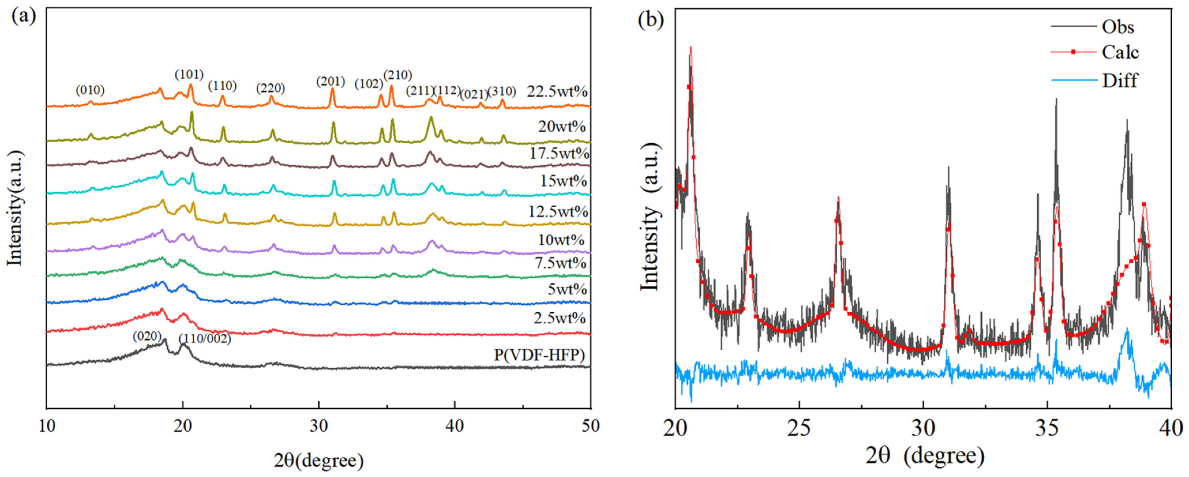
  27. Toraya, H. Crystal structure refinement of α-Si3N4 using synchrotron radiation powder diffraction data: Unbiased refinement strategy. J. Appl. Crystallogr. 2010, 33, 95–102. [Google Scholar] [CrossRef]
  28. Li, W.; Meng, Q.; Zheng, Y.; Zhang, Z.; Xia, W.; Xu, Z. Electric energy storage properties of poly(vinylidene fluoride). Appl. Phys. Lett. 2010, 96, 192905. [Google Scholar] [CrossRef]
  29. Cui, L.; Hu, M.; Wang, Q.; Xu, B.; Yu, D.; Liu, Z.; He, J. Prediction of novel hard phases of Si3N4: First-principles calculations. J. Solid State Chem. 2015, 228, 20–26. [Google Scholar] [CrossRef]
  30. Zhang, X.; Xia, W.; Liu, J.; Zhao, M.; Li, M.; Xing, J. PVDF-based and its Copolymer-Based Piezoelectric Composites: Preparation Methods and Applications. J. Electron. Mater. 2022, 51, 5528–5549. [Google Scholar] [CrossRef]
  31. Xia, W.; Xu, Z.; Wen, F.; Li, W.; Zhang, Z. Crystalline properties dependence of dielectric and energy storage properties of poly(vinylidene fluoride-chlorotrifluoroethylene). Appl. Phys. Lett. 2010, 97, 222905. [Google Scholar] [CrossRef]
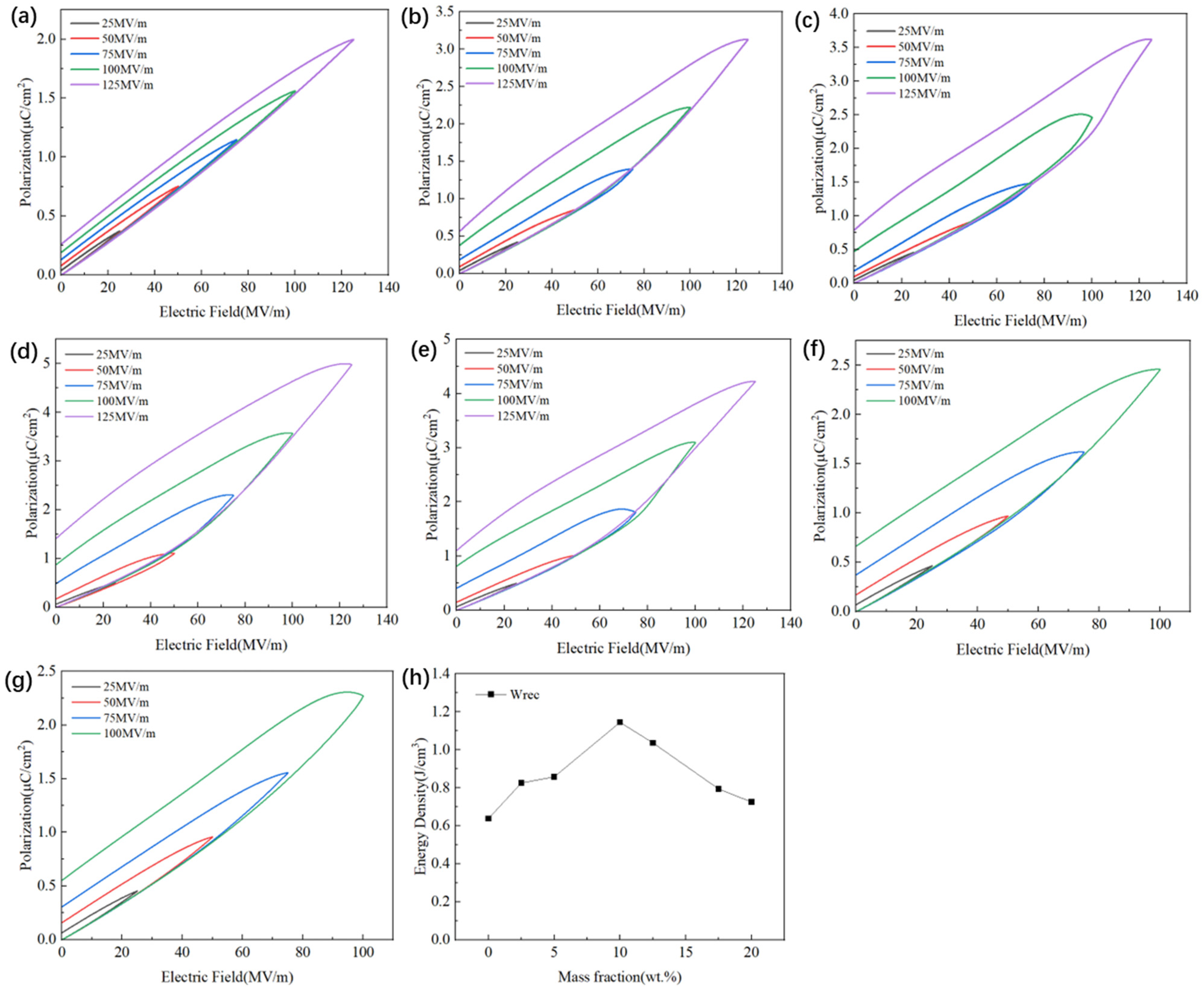
Figure 1. Schematic diagram of the preparation process of Si3N4/P(VDF-HFP) composite film.
Polymers 15 04264 g001
Figure 2. XRD pattern of Si3N4/P(VDF-HFP) composites. (a) XRD of different Si3N4 contents and (b) the refined result of Si3N4/filler.
Polymers 15 04264 g002
Figure 3. FTIR of Si3N4/P(VDF-HFP) composites with different Si3N4 contents.
Polymers 15 04264 g003
Figure 4. SEM images of P(VDF-HFP)-based two-phase composites with different Si3N4 contents: (a) 0 wt%, (b) 5 wt%, (c) 7.5 wt%, (d) 10 wt%, (e) 12.5 wt%, (f) 15 wt%, (g) 17.5 wt%, (h) 20 wt%, and (i) 22.5 wt%. EDS of (j) pure P(VDF-HFP) and (k) Si3N4/P(VDF-HFP) composite with 22.5 wt% Si3N4.
Polymers 15 04264 g004
Figure 5. Dielectric property–frequency patterns: (a) εr and (b) tan δ.
Polymers 15 04264 g005
Figure 6. Dielectric property–temperature patterns of Si3N4/P(VDF-HFP) composites at frequencies of 100 Hz, 1 kHz, 10 kHz, 100 kHz, and 1 MHz for (a) 0 wt%, (b) 2.5 wt%, (c) 5 wt%, (d) 7.5 wt%, (e) 10 wt%, (f) 12.5 wt%, (g) 15 wt%, and (h) 20 wt%. (i) Dielectric property–temperature patterns of all Si3N4/P(VDF-HFP) composites at the frequency of 1 kHz.
Polymers 15 04264 g006
Figure 7. Unipolar P-E curves of Si3N4/P(VDF-HFP) composites with different Si3N4 contents: (a) 0 wt%, (b) 2.5 wt%, (c) 5 wt%, (d) 10 wt%, (e) 12.5 wt%, (f) 17.5 wt%, (g) 20 wt%. (h) Wrec of composite materials with different Si3N4 contents at 100 MV/m.
Polymers 15 04264 g007
Table 1. Pm, Pr and Pm-Pr of Si3N4/P(VDF-HFP) composite film samples with different Si3N4 contents.
Si3N4 ContentsPmPrPm-Pr
0.0 wt%1.560.191.37
2.5 wt%2.230.381.85
5.0 wt%2.50.472.03
10.0 wt%3.570.872.7
12.5 wt%3.10.812.29
17.5 wt%2.450.671.78
20.0 wt%2.30.551.75
Disclaimer/Publisher’s Note: The statements, opinions and data contained in all publications are solely those of the individual author(s) and contributor(s) and not of MDPI and/or the editor(s). MDPI and/or the editor(s) disclaim responsibility for any injury to people or property resulting from any ideas, methods, instructions or products referred to in the content.

