

Effect of PEG Molecular Weight on the Polyurethane-Based Quasi-Solid-State Electrolyte for Dye-Sensitized Solar Cells


Abstract
:1. Introduction
2. Materials and Methods
2.1. Preparation of the Polyurethane Quasi-Solid-State Electrolyte (QSE)
2.2. Preparation of Dye-Sensitized Solar Cells
2.3. Characterization
3. Results and Discussion
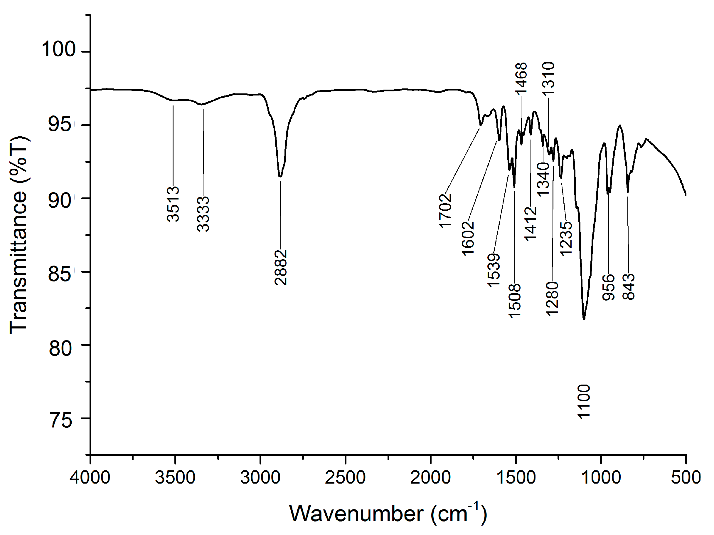
3.1. ATR−FTIR Analysis
3.2. Distribution Pattern
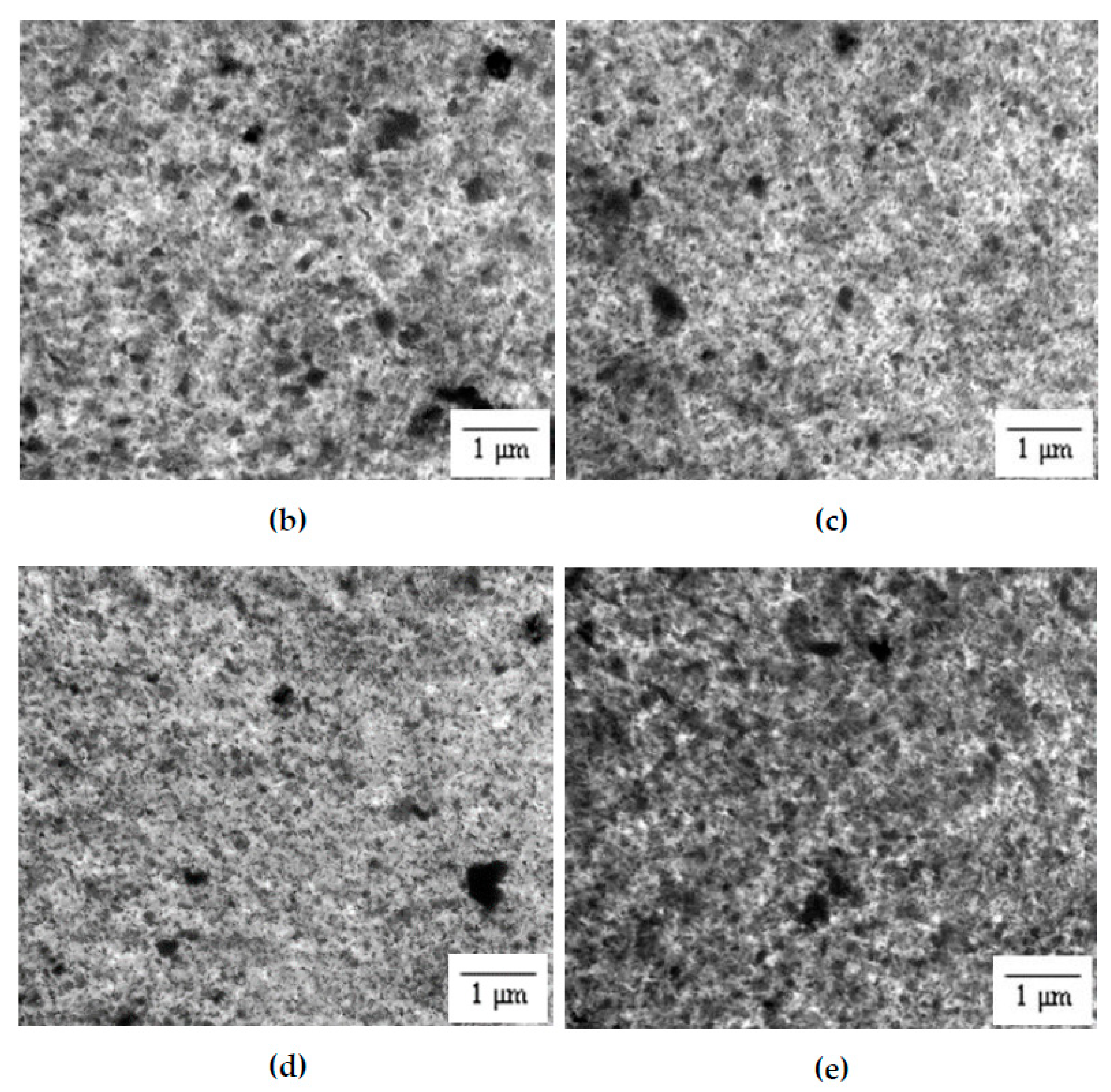
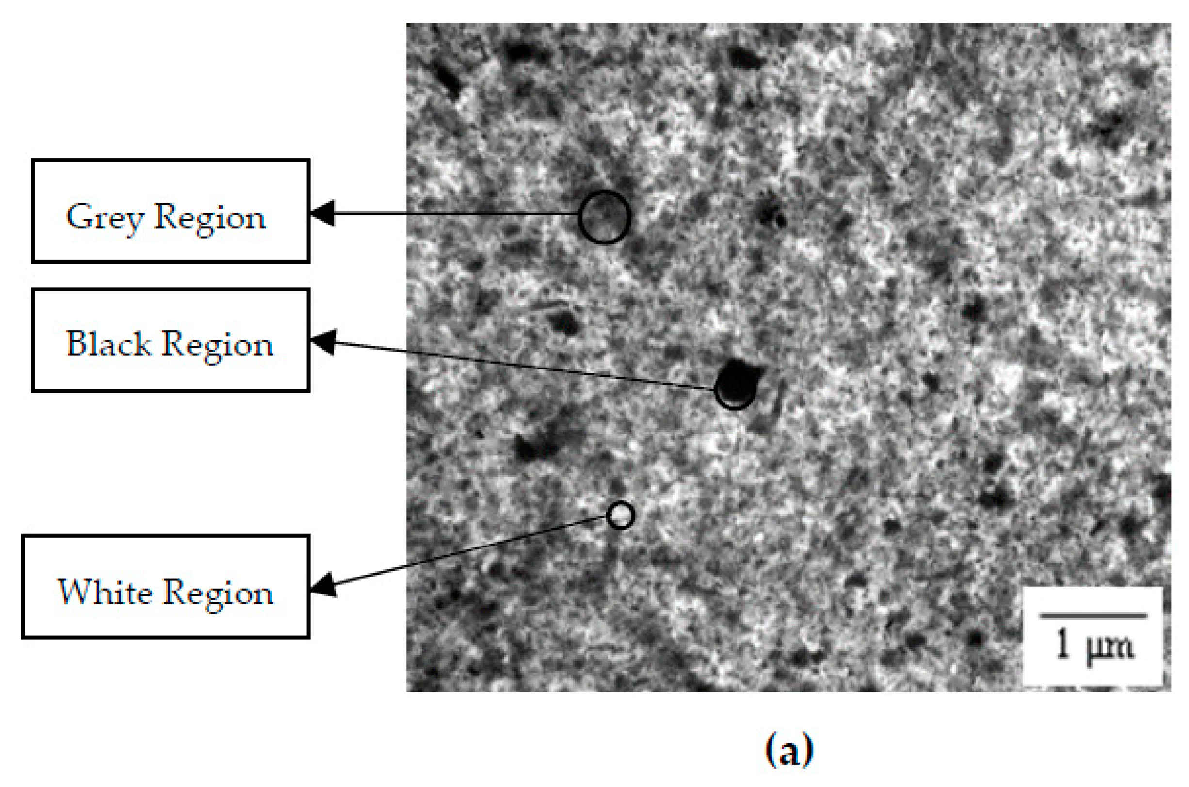
3.3. Surface Morphology
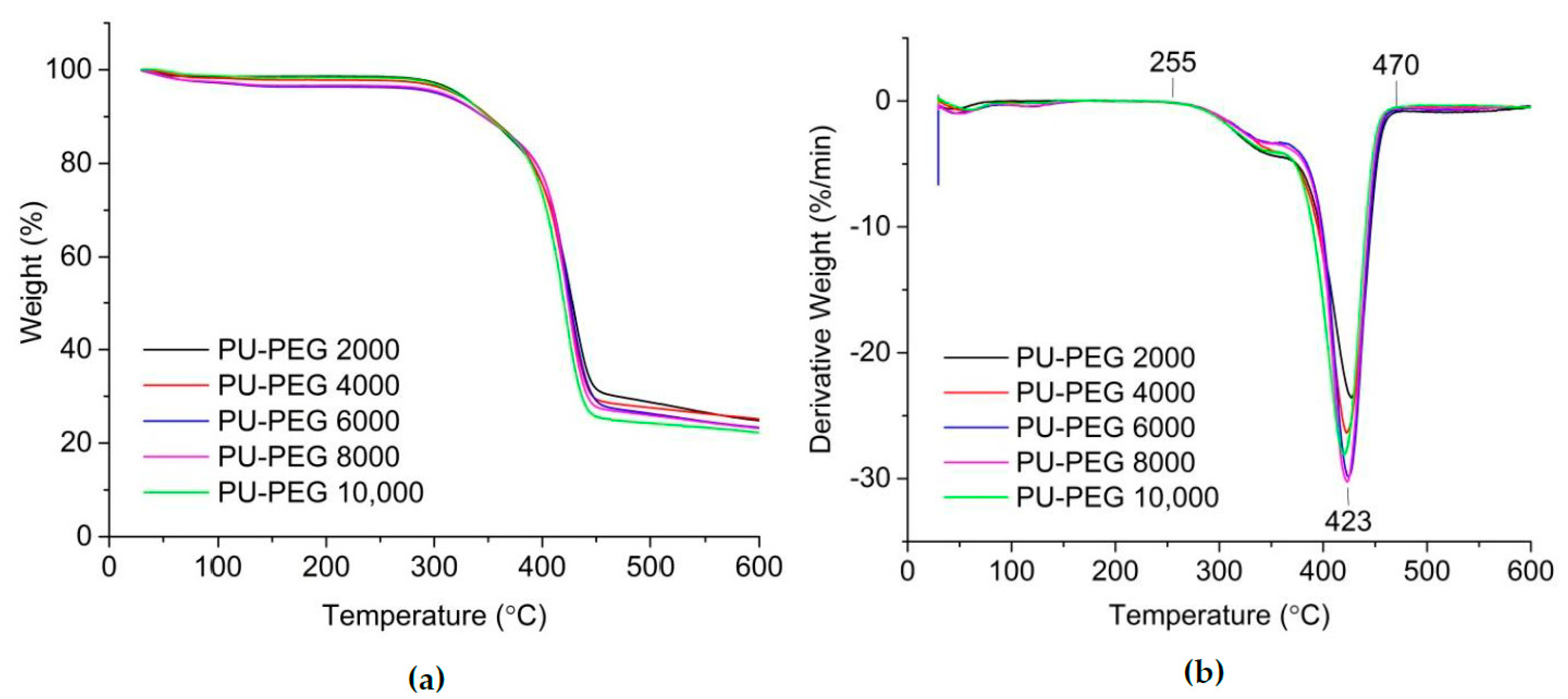
3.4. Thermal Stability
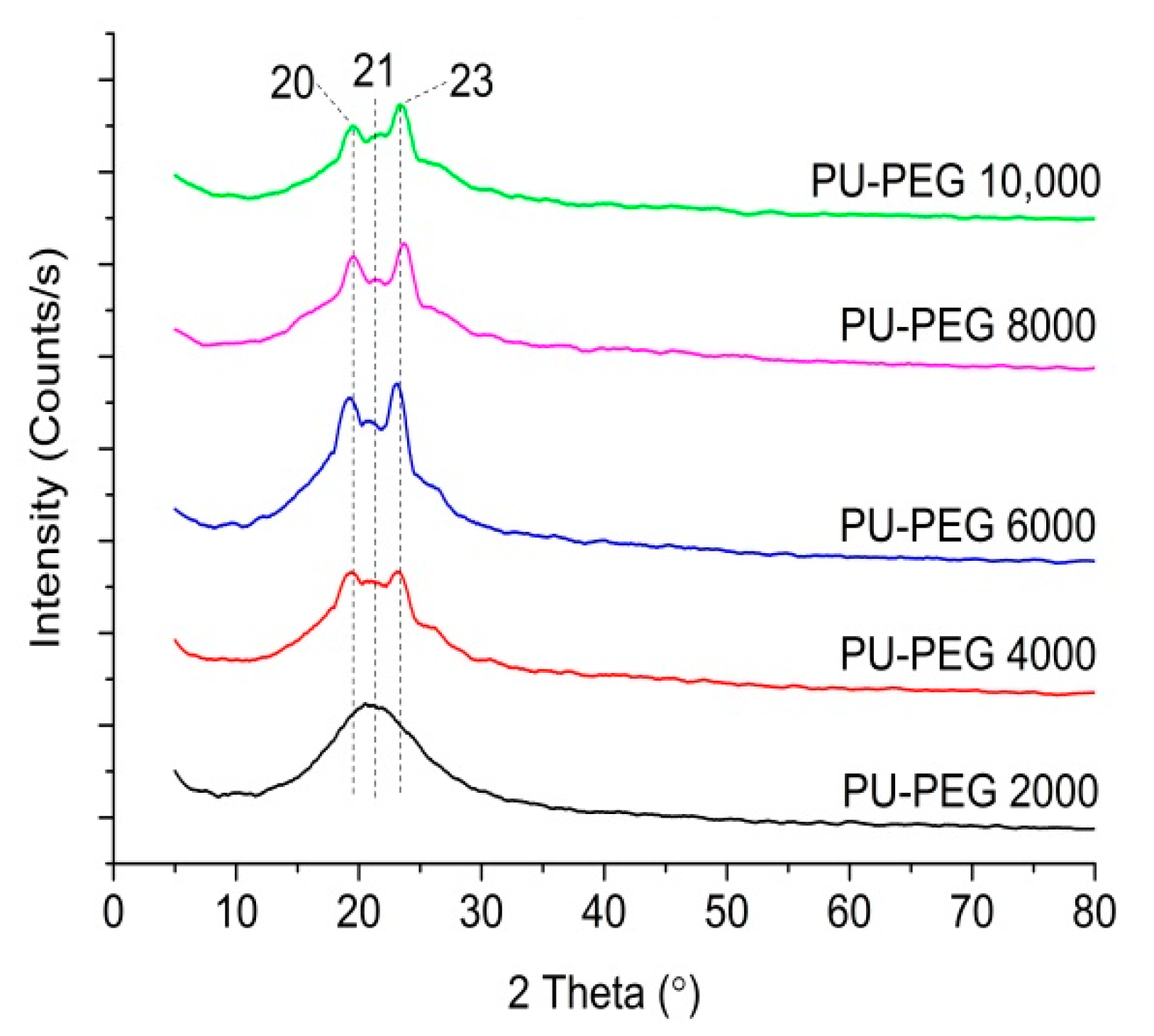
3.5. Structural Analysis
3.6. Gel Content
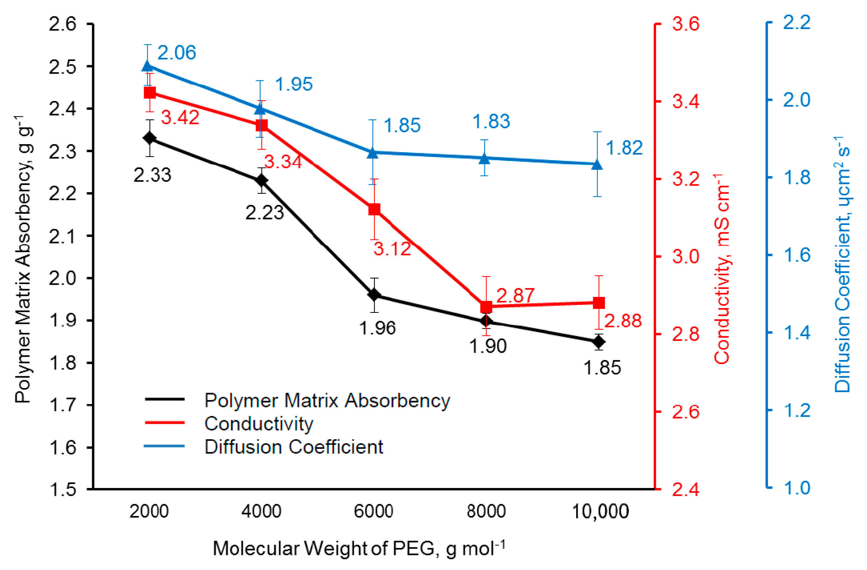
3.7. Polymer Matrix Absorbency, Electrical Property, and Electrochemical Property
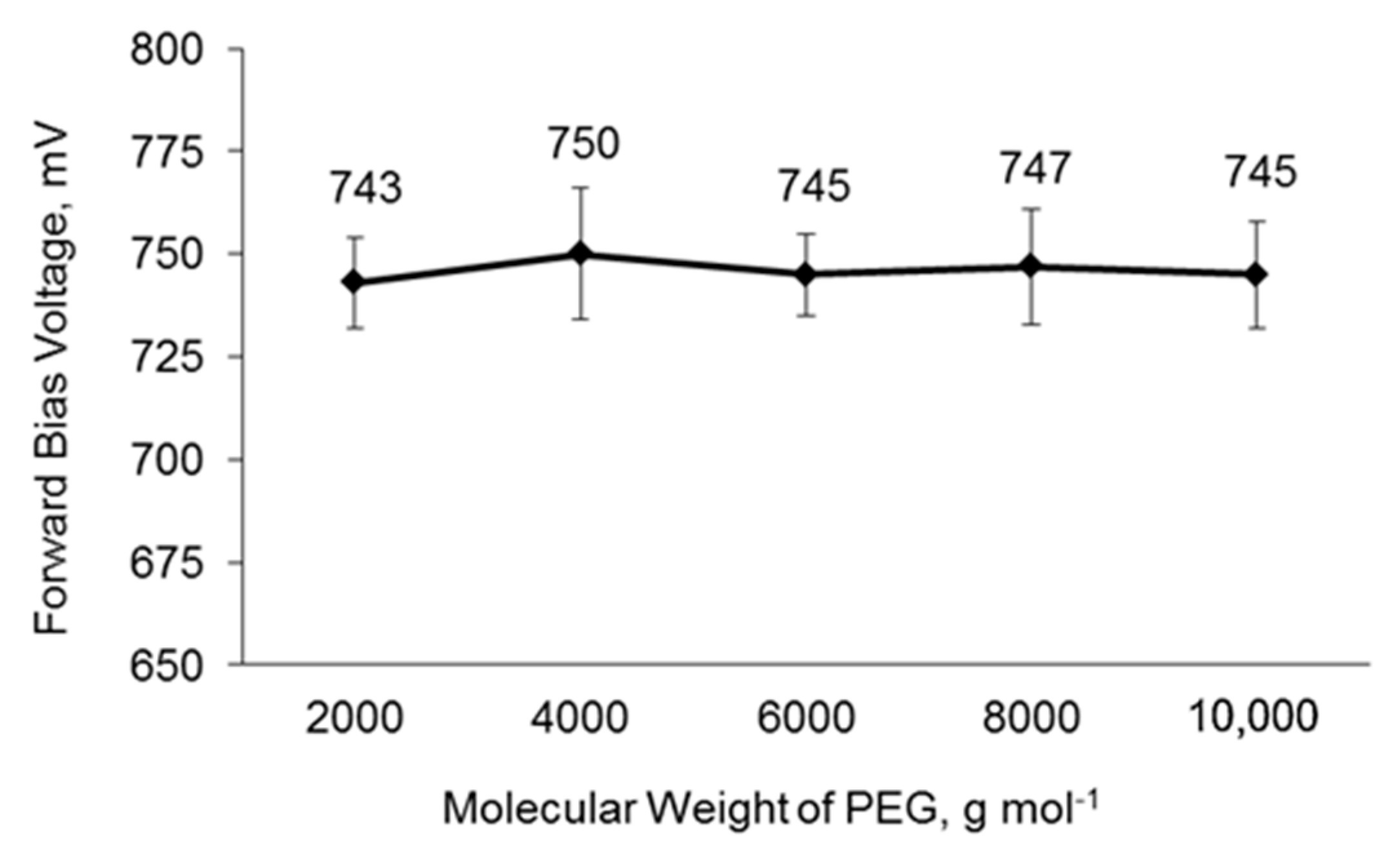
3.8. Charge Recombination of DSSCs
3.9. Photovoltaic Performance of DSSCs
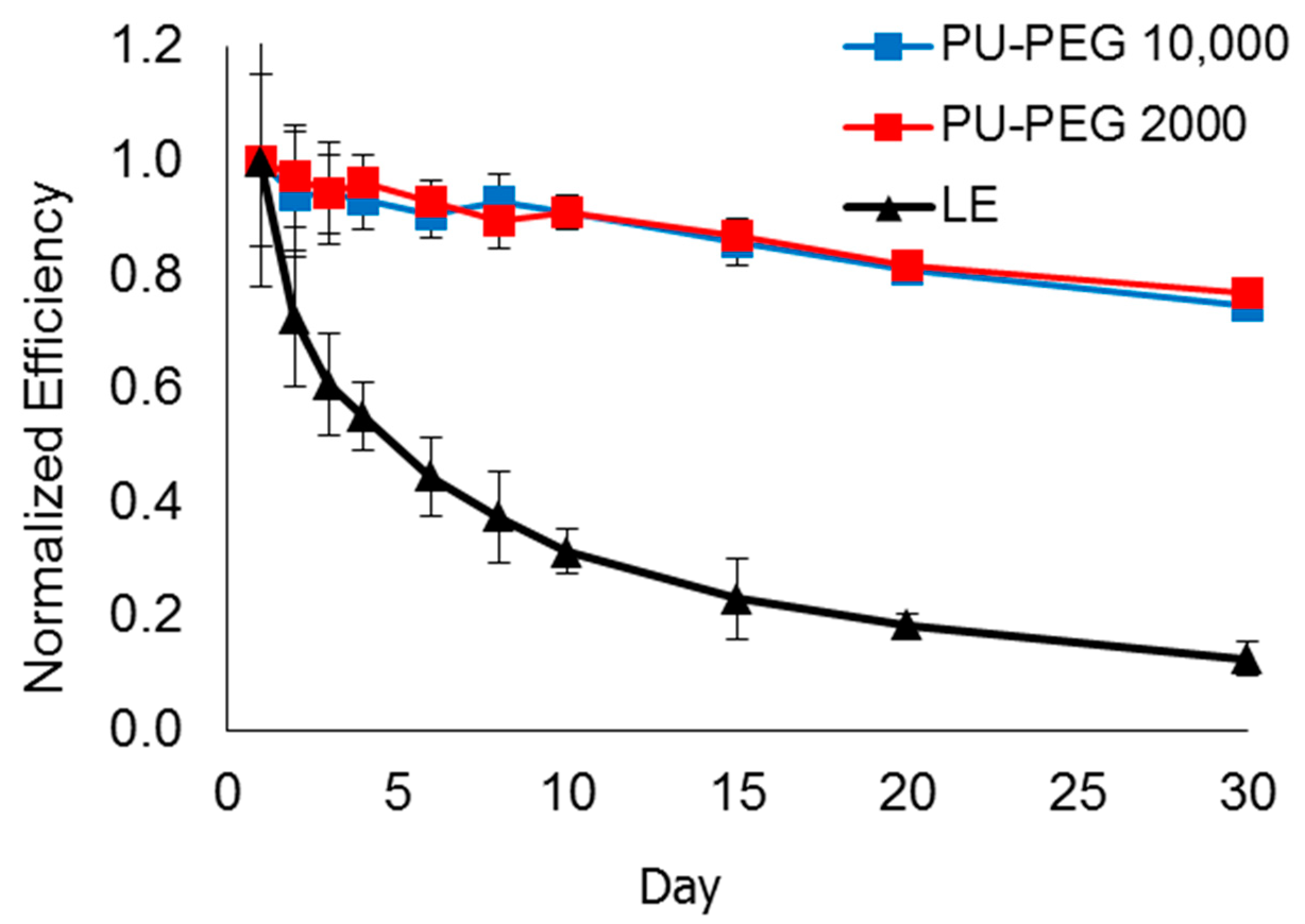
3.10. Lifespan of DSSCs
4. Conclusions
Author Contributions
Funding
Data Availability Statement
Acknowledgments
Conflicts of Interest
References
- Mathew, S.; Yella, A.; Gao, P.; Humphry-Baker, R.; Curchod, B.F.E.; Ashari-Astani, N.; Tavernelli, I.; Rothlisberger, U.; Nazeeruddin, M.K.; Grätzel, M. Dye-sensitized solar cells with 13% efficiency achieved through the molecular engineering of porphyrin sensitizers. Nat. Chem. 2014, 6, 242–247. [Google Scholar] [CrossRef] [PubMed]
- Huo, Z.; Dai, S.; Wang, K.; Kong, F.; Zhang, C.; Pan, X.; Fang, X. Nanocomposite gel electrolyte with large enhanced charge transport properties of an I3-/I-redox couple for quasi-solid-state dye-sensitized solar cells. Sol. Energy Mater. Sol. Cells 2007, 91, 1959–1965. [Google Scholar] [CrossRef]
- Kamenan, K.A.; Jagadeesh, A.; Kre, N.R.; Assanvo, E.F.; Soman, S.; Unni, K.N.N. Natural rubber (Hevea Brasiliensis)-based quasi-solid electrolyte as a potential candidate for arresting recombination and improving performance in aqueous dye-sensitized solar cells. J. Mater. Sci. Mater. Electron. 2021, 32, 14207–14216. [Google Scholar] [CrossRef]
- Raut, P.; Kishnani, V.; Mondal, K.; Gupta, A.; Jana, S.C. A review on gel polymer electrolytes for dye-sensitized solar cells. Micromachines 2022, 13, 680. [Google Scholar] [CrossRef] [PubMed]
- Jena, A.; Mohanty, S.P.; Kumar, P.; Naduvath, J.; Lekha, P.; Das, J.; Narula, H.K.; Mallick, S.; Bhargava, P.; Jena, A.; et al. Dye sensitized solar cells: A review. Trans. Indian Ceram. Soc. 2012, 71, 1–16. [Google Scholar] [CrossRef]
- Wu, J.; Lan, Z.; Hao, S.; Li, P.; Lin, J. Progress on the electrolytes for dye-sensitized solar cells. Pure Appl. Chem. 2008, 80, 2241–2258. [Google Scholar] [CrossRef]
- Wu, J.; Lan, Z.; Lin, J.; Huang, M.; Hao, S.; Fang, L. Influence of solvent on the poly (acrylic acid)-oligo-(ethylene glycol) polymer gel electrolyte and the performance of quasi-solid-state dye-sensitized solar cells. Electrochim. Acta 2007, 52, 7128–7135. [Google Scholar] [CrossRef]
- Zheng, J. Graphene tailored polymer gel electrolytes for 9.1% efficiency quasi-solid-state dye-sensitized solar cells. J. Power Sources 2017, 348, 239–245. [Google Scholar] [CrossRef]
- Wu, B.J.; Lan, Z.; Lin, J.; Huang, M.; Hao, S.; Sato, T.; Yin, S. A Novel Thermosetting gel electrolyte for stable quasi-solid-state dye-sensitized solar cells. Adv. Mater. 2007, 19, 4006–4011. [Google Scholar] [CrossRef]
- Li, Q.; Li, H.; Jin, X.; Chen, Z. PEDOT and derivatives tailored conducting gel electrolytes for high-efficiency quasi-solid-state dye-sensitized solar cells. Electrochim. Acta 2018, 260, 413–419. [Google Scholar] [CrossRef]
- Li, P.; Yuan, S.; Tang, Q.; He, B. Robust conducting gel electrolytes for efficient quasi-solid-state dye-sensitized solar cells. Electrochim. Acta 2014, 137, 57–64. [Google Scholar] [CrossRef]
- Lan, Z.; Wu, J.; Lin, J.; Huang, M.; Yin, S.; Sato, T. Influence of molecular weight of PEG on the property of polymer gel electrolyte and performance of quasi-solid-state dye-sensitized solar cells. Electrochim. Acta 2007, 52, 6673–6678. [Google Scholar] [CrossRef]
- Yuan, S.; Tang, Q.; He, B.; Yu, L. Conducting gel electrolytes with microporous structures for efficient quasi-solid-state dye-sensitized solar cells. J. Power Sources 2015, 273, 1148–1155. [Google Scholar] [CrossRef]
- Tang, Z.; Liu, Q.; Tang, Q.; Wu, J.; Wang, J.; Chen, S.; Cheng, C.; Yu, H.; Lan, Z.; Lin, J.; et al. Electrochimica acta preparation of PAA-G-CTAB/PANI polymer based gel-electrolyte and the application in quasi-solid-state dye-sensitized solar cells. Electrochim. Acta 2011, 58, 52–57. [Google Scholar] [CrossRef]
- Li, Q.; Tang, Q.; He, B.; Yang, P. Full-ionic liquid gel electrolytes: Enhanced photovoltaic performances in dye-sensitized solar cells. J. Power Sources 2014, 264, 83–91. [Google Scholar] [CrossRef]
- Yang, Y.; Tao, J.; Jin, X.; Qin, Q. New microporous polymer electrolyte based on polysiloxane grafted with imidazolium iodide moieties for DSSC. Int. J. Photoenergy 2011, 2011, 405738. [Google Scholar] [CrossRef]
- Yang, H.; Ileperuma, O.A.; Shimomura, M.; Murakami, K. Effect of ultra-thin polymer membrane electrolytes on dye-sensitized solar cells. Sol. Energy Mater. Sol. Cells 2009, 93, 1083–1086. [Google Scholar] [CrossRef]
- Priya, A.R.S.; Subramania, A.; Jung, Y.; Kim, K. High-performance quasi-solid-state dye-sensitized solar cell based on an electrospun PVdF-HFP membrane electrolyte. Langmuir 2008, 24, 9816–9819. [Google Scholar] [CrossRef]
- Angaiah, S.; Murugadoss, V.; Arunachalam, S.; Panneerselvam, P.; Krishnan, S. Influence of various ionic liquids embedded electrospun polymer membrane electrolytes on the photovoltaic performance of DSSC. Eng. Sci. 2018, 4, 44–51. [Google Scholar] [CrossRef]
- Vinoth, S.; Kanimozhi, G.; Kumar, H.; Srinadhu, E.S.; Satyanarayana, N. High conducting nanocomposite electrospun PVDF-HFP/TiO 2 quasi-solid electrolyte for dye-sensitized solar cell. J. Mater. Sci. Mater. Electron. 2019, 30, 1199–1213. [Google Scholar] [CrossRef]
- Zhao, J.; Jo, S.; Kim, D. Photovoltaic performance of dye-sensitized solar cells assembled with electrospun polyacrylonitrile/silica-based fibrous composite membrance. Electrochim. Acta 2014, 142, 261–267. [Google Scholar] [CrossRef]
- Murugadoss, V.; Arunachalam, S.; Elayappan, V.; Angaiah, S. Development of electrospun PAN/CoS nanocomposite membrane electrolyte for high-performance DSSC. Ionics 2018, 24, 4071–4080. [Google Scholar] [CrossRef]
- Dissanayake, S.S.; Dissanayake, M.A.K.L.; Seneviratne, V.A. Performance of dye sensitized solar cells fabricated with electrospun polymer nanofiber based electrolyte. Mater. Today Proc. 2016, 3, S104–S111. [Google Scholar] [CrossRef]
- Saidi, N.M.; Goh, Z.L.; Arif, H.M.; Farhana, N.K.; Ramesh, S.; Ramesh, K. Consolidation of ion promoters into quasi solid-state (QSS) polymer electrolytes for dye-sensitized solar cells (DSSCs). Solid State Ion. 2021, 363, 115592. [Google Scholar] [CrossRef]
- Chen, K.; Liu, C.; Huang, H.; Tsai, C.; Chen, F. Polyvinyl butyral-based thin film polymeric electrolyte for dye-sensitized solar cell with long-term stability. Int. J. Electrochem. Sci. 2013, 8, 3524–3539. [Google Scholar]
- Li, Q.; Chen, X.; Tang, Q.; Cai, H.; Qin, Y.; He, B.; Li, M.; Jin, S.; Liu, Z. Enhanced photovoltaic performances of quasi-solid-state dye-sensitized solar cells using a novel conducting gel electrolyte. J. Power Sources 2014, 248, 923–930. [Google Scholar] [CrossRef]
- Weerasinghe, A.M.J.S.; Dissanayake, M.A.K.L.; Senadeera, G.K.R. Application of electrospun cellulose acetate nanofibre membrane based quasi-solid state electrolyte for dye sensitized solar Cells. Ceylon J. Sci. 2017, 46, 93–98. [Google Scholar] [CrossRef]
- Sj, L.; Pw, L.; Fy, H.; Kw, C.; Yl, T. Correlation between dye-sensitized solar cell performance and internal resistance using electrochemical impedance spectroscopy. Phys. Chem. Biophys. 2015, 5, 1. [Google Scholar] [CrossRef]
- Liow, K.S.; Sipaut, C.S.; Jafarzadeh, M. Polypyrrole- and polyaniline-surface modified nanosilica as quasi-solid state electrolyte ingredients for dye-sensitized solar cells. J. Mater. Sci. Mater. Electron. 2018, 29, 21097–21108. [Google Scholar] [CrossRef]
- Liow, K.S.; Sipaut, C.S.; Mansa, R.F.; Ung, M.C.; Jafarzadeh, M. Formulated quasi-solid state electrolyte based on polypyrrole/polyaniline—Polyurethane nanocomposite for dye-sensitized solar cell. J. Mater. Sci. Mater. Electron. 2018, 29, 11653–11663. [Google Scholar] [CrossRef]
- Boonsin, R.; Sudchanham, J.; Panusophon, N.; Sae-heng, P. Dye-sensitized solar cell with poly (acrylic acid-co-acrylonitrile)-based gel polymer electrolyte. Mater. Chem. Phys. 2012, 132, 993–998. [Google Scholar] [CrossRef]
- Sethupathy, M.; Pandey, P.; Manisankar, P. Development of quasi-solid-state dye-sensitized solar cell based on an electrospun polyvinylidene fluoride—Polyacrylonitrile membrane electrolyte. J. Appl. Polym. Sci. 2014, 131, 40022. [Google Scholar] [CrossRef]
- Vinoth, S.; Kanimozhi, G.; Hari Prasad, K.; Kumar, H.; Srinadhu, E.S.; Satyanarayana, N. Enhanced ionic conductivity of electrospun nanocomposite (PVDF-HFP 1 TiO2 nanofibers fillers) polymer fibrous membrane electrolyte for DSSC application. Polym. Compos. 2018, 40, 1585–1594. [Google Scholar] [CrossRef]
- Spasova, M.; Manolova, N.; Markova, N.; Rashkov, I. Superhydrophobic PVDF and PVDF-HFP nanofibrous mats with antibacterial and anti-biofouling properties. Appl. Surf. Sci. 2016, 363, 363–371. [Google Scholar] [CrossRef]
- He, S.; Zhai, S.; Zhang, C.; Xue, Y.; Yang, W.; Lin, J. Effect of sulfonation degree and PVDF content on the structure and transport Properties of SPEEK/PVDF blend membranes. Polymers 2019, 11, 676. [Google Scholar] [CrossRef]
- Bliznyuk, V.N.; Baig, A.; Singamaneni, S.; Pud, A.A.; Fatyeyeva, K.Y.; Shapoval, G.S. Effects of surface and volume modification of poly (vinylidene fluoride) by polyaniline on the structure and electrical properties of their composites. Polymer 2005, 46, 11728–11736. [Google Scholar] [CrossRef]
- Wang, X.; Xiao, C.; Liu, H.; Huang, Q.; Hao, J.; Fu, H. Poly (vinylidene fluoride-hexafluoropropylene) porous membrane with controllable structure and applications in efficient oil/water separation. Materials 2018, 11, 443. [Google Scholar] [CrossRef]
- Lee, J.; Choi, H.; Park, S.; Won, D.; Park, H.; Kim, J.; Lee, C. Fabrications of poly (vinylidenefluoride-co-hexafluoropropylene) nanofibers containing inorganic filler by electrospinning technique and its application to dye-sensitized solar cells. Mol. Cryst. Liq. Cryst. 2010, 519, 234–244. [Google Scholar] [CrossRef]
- Ibrahim, S.; Ahmad, A.; Mohamed, N.S. Comprehensive studies on polymer electrolyte and dye-sensitized solar cell developed using castor oil-based polyurethane. J. Solid State Electrochem. 2018, 22, 461–470. [Google Scholar] [CrossRef]
- Su’ait, M.S.; Jumaah, F.N.; Faizzi, H.M.; Mamat, S.; Ludin, N.A.; Farhan, W.A.; Haron, A.; Atifah, N.; Latif, M.N.; Badri, K.H.; et al. Palm-based polyurethane-ionic liquid gel polymer electrolyte for quasi-solid state dye sensitized solar cell. Ind. Crops Prod. 2018, 113, 406–413. [Google Scholar] [CrossRef]
- Lee, H.S.; Han, C.H.; Sung, Y.M.; Sekhon, S.S.; Kim, K.J. Gel electrolyte based on UV-cured polyurethane for dye-sensitized solar cells. Curr. Appl. Phys. 2011, 11, S158–S162. [Google Scholar] [CrossRef]
- Chuang, P.Y.; Chang, L.Y.; Chuang, C.N.; Chen, S.H.; Lin, J.J.; Ho, K.C.; Hsieh, K.H. A novel gel electrolyte based on polyurethane for highly efficient in dye-sensitized solar cells. J. Polym. Res. 2016, 23, 214. [Google Scholar] [CrossRef]
- Li, Q.; Chen, H.; Li, P.; Qin, Y.; Li, M.; He, B.; Chu, L.; Tang, Q. Quasi-solid-state dye-sensitized solar cell from polyaniline integrated poly (hexamethylene diisocynate tripolymer/polyethylene glycol) gel electrolyte. J. Mater. Chem. A 2015, 1, 5326–5332. [Google Scholar] [CrossRef]
- Rayung, M.; Aung, M.M.; Su’Ait, M.S.; Chuah Abdullah, L.; Ahmad, A.; Lim, H.N. Performance analysis of jatropha oil-based polyurethane acrylate gel polymer electrolyte for dye-sensitized solar cells. ACS Omega 2020, 5, 14267–14274. [Google Scholar] [CrossRef] [PubMed]
- Liow, K.S.; Sipaut, C.S.; Ung, M.C.; Dayou, J. Effect of incorporating different polyaniline-surface modified nanosilica content into polyurethane-based quasi-solid-state electrolyte for dye-sensitized solar cells. J. Appl. Polym. Sci. 2020, 137, 49147. [Google Scholar] [CrossRef]
- Wen, T.C.; Du, Y.L.; Digar, M. Compositional effect on the morphology and ionic conductivity of thermoplastic polyurethane based electrolytes. Eur. Polym. J. 2002, 38, 1039–1048. [Google Scholar] [CrossRef]
- Sa’Adun, N.N.; Subramaniam, R.; Kasi, R. Development and characterization of poly(1-vinylpyrrolidone-co-vinyl acetate) copolymer based polymer electrolytes. Sci. World J. 2014, 2014, 254215. [Google Scholar] [CrossRef]
- Wong, C.S.; Badri, K.H.; Ataollahi, N.; Law, K.P.; Su, M.S.; Hassan, N.I. Synthesis of new bio-based solid polymer electrolyte effect of NCO/OH ratio on their chemical, thermal properties and ionic conductivity. Int. J. Chem. Mol. Eng. 2014, 8, 1234–1250. [Google Scholar]
- Chen, C.C.; Ting, C.C. Photoelectrode fabrication of dye-sensitized nanosolar cells using multiple spray coating technique. Int. J. Photoenergy 2013, 2013, 629059. [Google Scholar] [CrossRef]
- Chen, Y.S.; Lee, J.N.; Tsai, S.Y.; Ting, C.C. Manufacture of dye-sensitized nano solar cells and THEIR I-V curve measurements. Mater. Sci. Forum 2008, 594, 324–330. [Google Scholar] [CrossRef]
- Chang, H.; Chen, W.A.; Kao, M.J. An investigation of TiO2 thin film in dye sesitized solar cells by electrophoresis method. Mater. Sci. Forum 2007, 561–565, 2171–2174. [Google Scholar] [CrossRef]
- Ung, M.C.; Sipaut, C.S.; Dayou, J.; Liow, K.S.; Kulip, J.; Mansa, R.F. Fruit Based Dye Sensitized Solar Cells. In IOP Conference Series: Materials Science and Engineering; IOP Publishing: Bristol, UK, 2017; Volume 217, p. 012003. [Google Scholar] [CrossRef]
- Wang, Z.; Yang, X.; Zhou, Y.; Liu, C. Mechanical and thermal properties of polyurethane films from peroxy-acid wheat straw lignin. BioResources 2013, 8, 3833–3843. [Google Scholar] [CrossRef]
- Strankowski, M.; Strankowska, J.; Gazda, M.; Piszczyk, L.; Nowaczyk, G.; Jurga, S. Thermoplastic polyurethane/(organically modified montmorillonite) nanocomposites produced by in situ polymerization. Express Polym. Lett. 2012, 6, 610–619. [Google Scholar] [CrossRef]
- Kannan, M.; Bhagawan, S.S.; Thomas, S.; Joseph, K. Thermogravimetric analysis and differential scanning calorimetric studies on nanoclay-filled TPU/PP blends. J. Therm. Anal. Calorim. 2013, 112, 1231–1244. [Google Scholar] [CrossRef]
- Kang, S.H.; Ku, D.C.; Lim, J.H.; Yang, Y.K.; Kwak, N.S.; Hwang, T.S. Characterization for pyrolysis of thermoplastic polyurethane by thermal analyses. Macromol. Res. 2005, 13, 212–217. [Google Scholar] [CrossRef]
- Vega-baudrit, J.; Carballo, S.M.; De Adhesión, L.; De Alicante, U.; Rica, C. Thermoplastic polyurethanes-fumed silica composites: Influence of NCO/OH in the study of thermal and rheological properties and morphological characteristics. In Thermoplastic—Composite Materials; El-Sonbati, A., Ed.; Books on Demand: Norderstedt, Germany, 2012; pp. 12–24. ISBN 978-953-51-0310-3. [Google Scholar]
- Agarwala, S.; Thummalakunta, L.N.S.A.; Cook, C.A.; Peh, C.K.N.; Wong, A.S.W.; Ke, L.; Ho, G.W. Co-existence of LiI and KI in filler-free, quasi-solid-state electrolyte for efficient and stable dye-sensitized solar cell. J. Power Sources 2011, 196, 1651–1656. [Google Scholar] [CrossRef]
- Jawad, M.; Al-Ajaj, E.; Suhail, M.; Majid, S.R. Efficiency enhancement of photovoltaic performance of quasi-solid state dye Sensitized solar cell with TPAI and KI binary iodide salt mixture. Adv. Phys. Theor. Appl. 2014, 34, 51–60. [Google Scholar]
- Yang, Y.; Hu, H.; Zhou, C.H.; Xu, S.; Sebo, B.; Zhao, X.Z. Novel agarose polymer electrolyte for quasi-solid state dye-sensitized solar cell. J. Power Sources 2011, 196, 2410–2415. [Google Scholar] [CrossRef]
- Liang, G.; Zhong, Z.; Qu, S.; Wang, S.; Liu, K.; Wang, J.; Xu, J. Novel in situ crosslinked polymer electrolyte for solid-state dye-sensitized solar cells. J. Mater. Sci. 2013, 48, 6377–6385. [Google Scholar] [CrossRef]
- Hao, F.; Lin, H.; Zhang, J.; Zhuang, D.; Liu, Y.; Li, J. Influence of iodine concentration on the photoelectrochemical performance of dye-sensitized solar cells containing non-volatile electrolyte. Electrochim. Acta 2010, 55, 7225–7229. [Google Scholar] [CrossRef]
- Hauch, A.; Georg, A. Diffusion in the electrolyte and charge-transfer reaction at the platinum electrode in dye-sensitized solar cells. Electrochim. Acta 2001, 46, 3457–3466. [Google Scholar] [CrossRef]
- Hsu, H.L.; Tien, C.F.; Yang, Y.T.; Leu, J. Dye-sensitized solar cells based on agarose gel electrolytes using allylimidazolium Iodides and environmentally benign solvents. Electrochim. Acta 2013, 91, 208–213. [Google Scholar] [CrossRef]
- Krawczak, E.; Zdyb, A. The influence of the dye adsorption time on the DSSC performance. E3S Web Conf. 2019, 100, 00040. [Google Scholar] [CrossRef]
- Yu, H.; Zhang, S.; Zhao, H.; Will, G.; Liu, P. An efficient and low-cost TiO2 compact layer for performance improvement of dye-sensitized solar cells. Electrochim. Acta 2009, 54, 1319–1324. [Google Scholar] [CrossRef]
- Huang, K.C.; Vittal, R.; Ho, K.C. Effects of crown ethers in nanocomposite silica-gel electrolytes on the performance of quasi-solid-state dye-sensitized solar cells. Sol. Energy Mater. Sol. Cells 2010, 94, 675–679. [Google Scholar] [CrossRef]
- Park, J.H.; Jun, Y.; Yun, H.G.; Lee, S.Y.; Kang, M.G. Fabrication of an efficient dye-sensitized solar cell with stainless steel substrate. J. Electrochem. Soc. 2008, 155, F145. [Google Scholar] [CrossRef]
- Malay, O.; Oguz, O.; Kosak, C.; Yilgor, E.; Yilgor, I. Polyurethaneurea E silica nanocomposites: Preparation and investigation of the structure E property behavior. Polymer 2013, 54, 5310–5320. [Google Scholar] [CrossRef]
- Petrini, P.; Fare, S.; Piva, A.; Tanzi, M. Design, synthesis and properties of polyurethane hydrogels for tissue engineering. J. Mater. Sci. Mater. Med. 2003, 14, 683–686. [Google Scholar] [CrossRef] [PubMed]
- Ren, Z.Y.; Wu, H.P.; Ma, J.M.; Ma, D.Z. FTIR studies on the model polyurethane hard segments based on a new waterborne chain extender dimethylol butanoic acid. Chin. J. Polym. Sci. 2004, 22, 225–230. [Google Scholar]
- Wong, C.S. Chemical analyses of palm kernel oil-based polyurethane prepolymer. Mater. Sci. Appl. 2012, 3, 78–86. [Google Scholar] [CrossRef]
- Asefnejad, A.; Khorasani, M.T.; Behnamghader, A.; Farsadzadeh, B.; Bonakdar, S. Manufacturing of biodegradable polyurethane scaffolds based on polycaprolactone using a phase separation method: Physical properties and in vitro assay. Int. J. Nanomed. 2011, 6, 2375–2384. [Google Scholar] [CrossRef] [PubMed]
- Shriner, R.L.; Hermann, C.K.F.; Morrill, T.C.; Curtin, D.Y.; Fuson, R.C. The Systematic Identification of Organic Compounds, 8th ed.; John Wiley & Sons, Inc.: Hoboken, NJ, USA, 2004. [Google Scholar]
- Gogoi, R.; Alam, S. Study of effect of NCO/OH molar ratio and molecular weight of polyol on the physico-mechanical properties of polyurethane plaster cast study of effect of NCO/OH molar ratio and molecular weight of polyol on the physico-mechanical properties of polyure. World Appl. Sci. J. 2013, 21, 276–283. [Google Scholar] [CrossRef]
- Gite, V.V.; Mahulikar, P.P.; Hundiwale, D.G.; Kapadi, U.R. Polyurethane coatings using trimer of isophorone diisocyanate. J. Sci. Ind. Res. 2004, 63, 348–354. [Google Scholar]
- Plisko, T.V.; Bildyukevich, A.V.; Usosky, V.V.; Volkov, V.V. Influence of the concentration and molecular weight of polyethylene glycol on the structure and permeability of polysulfone hollow fiber membranes. Pet. Chem. 2016, 56, 321–329. [Google Scholar] [CrossRef]
- Yan, W.; Han, Z.J.; Phung, B.T.; Faupel, F.; Ostrikov, K.K. High-voltage insulation organic-inorganic nanocomposites by plasma polymerization. Materials. 2014, 7, 563–575. [Google Scholar] [CrossRef]
- Xia, H.S.; Song, M.; Zhang, Z.Y.; Richardson, M. Microphase separation, stress relaxation, and creep behavior of polyurethane nanocomposites. J. Appl. Polym. Sci. 2007, 103, 2992–3002. [Google Scholar] [CrossRef]
- Deepa, P.; Jayakannan, M. Microporous polyurethane: Synthesis and investigation of the mechanism of the pore formation. J. Polym. Sci. Part B Polym. Phys. 2006, 44, 1296–1308. [Google Scholar] [CrossRef]
- Chen, K.; Leon Yu, T.; Chen, Y.; Lin, T.; Liu, W. Soft- and hard-segmental phase segregation of polyester-based polyurethane. J. Polym. Res. 2001, 8, 99–109. [Google Scholar] [CrossRef]
- Silver, J.H.; Myers, C.W.; Lim, F.; Cooper, S.L. Effect of polyol molecular-weight on the physical-properties and hemocompatibility of polyurethanes containing polyethylene oxide macroglycols. Biomaterials 1994, 15, 695–704. [Google Scholar] [CrossRef]
- Lin, Y.; Chou, N.; Chen, K.; Ho, G.; Chang, C.; Wang, S.; Chu, S.; Hsieh, K. Effect of soft segment lenght on properties of hydrophilic/hydrophobic polyurethanes. Polym. Int. 2008, 57, 171–180. [Google Scholar] [CrossRef]
- Trovati, G.; Sanches, E.A.; Neto, S.C.; Mascarenhas, Y.P.; Chierice, G.O. Characterization of polyurethane resins by FTIR, TGA, and XRD. J. Appl. Polym. Sci. 2010, 115, 263–268. [Google Scholar] [CrossRef]
- Amado, F.D.R.; Rodrigues, L.F.; Rodrigues, M.A.S.; Bernardes, A.M.; Ferreira, J.Z.; Ferreira, C.A. Development of polyurethane/polyaniline membranes for zinc recovery through electrodialysis. Desalination 2005, 186, 199–206. [Google Scholar] [CrossRef]
- Wen, T.C.; Hung, S.L.; Digar, M. Effect of polypyrrole on the morphology and ionic conductivity of TPU electrolyte containing LiClO4. Synth. Met. 2001, 118, 11–18. [Google Scholar] [CrossRef]
- Bagdi, K.; Molnár, K.; Sajó, I.; Pukánszky, B. Specific interactions, structure and properties in segmented polyurethane elastomers. Express Polym. Lett. 2011, 5, 417–427. [Google Scholar] [CrossRef]
- Çakmak, E.G.; Dalgakiran, D.; Güner, F.S. Castor oil and PEG-based shape memory polyurethane films: Effect of chain extender amount on some polymer properties and performance. Turkish J. Chem. 2018, 42, 1161–1173. [Google Scholar] [CrossRef]
- Pielichowski, K.; Flejtuch, K. Differential scanning calorimetry studies on poly (ethylene glycol) with different molecular weights for thermal energy storage materials. Polym. Adv. Technol. 2002, 13, 690–696. [Google Scholar] [CrossRef]
- Majumdar, R.; Alexander, K.S.; Riga, A.T. Physical characterization of polyethylene glycols by thermal analytical technique and the effect of humidity and molecular weight. Pharmazie 2009, 65, 343–347. [Google Scholar] [CrossRef]
- Rodrigues, P.C.; Akcelrud, L. Networks and blends of polyaniline and polyurethane: Correlations between composition and thermal, dynamic mechanical and electrical properties. Polymer 2003, 44, 6891–6899. [Google Scholar] [CrossRef]
- Gurunathan, T.; Rao, C.R.K.; Narayan, R.; Raju, K.V.S.N. Polyurethane conductive blends and composites: Synthesis and applications perspective. J. Mater. Sci. 2013, 48, 67–80. [Google Scholar] [CrossRef]
- Oka, O.; Kiyohara, O. Electrical and mechanical properties of crosslinked polyanilines. Synth. Met. 1993, 55, 999–1004. [Google Scholar] [CrossRef]
- Amado, F.D.R.; Rodrigues, L.F.; Forte, M.M.; Ferreira, C. Properties evaluation of the membranes synthesized with castor oil polyurethane and polyaniline. Polym. Eng. Sci. 2006, 46, 1485–1489. [Google Scholar] [CrossRef]
- Das, S.; Pandey, P.; Mohanty, S.; Nayak, S.K. Materials Express. Mater. Express 2015, 5, 377–389. [Google Scholar] [CrossRef]
- Semsarzadeh, M.A.; Navarchian, A.H. Effects of NCO/OH ratio and catalyst concentration on structure, thermal stability, and crosslink density of poly (urethane-isocyanurate). J. Appl. Polym. Sci. 2003, 90, 963–972. [Google Scholar] [CrossRef]
- Li, X.; Zhang, D.; Yin, X.J.; Chen, S.; Shi, J.; Sun, Z.; Huang, S. The effects of polymer gel electrolyte composition on performance of quasi-solid-state dye-sensitized solar cells. J. Solid State Electrochem. 2011, 15, 1271–1277. [Google Scholar] [CrossRef]
- Yoshikawa, H.; Hino, T.; Kuramoto, N. Effect of temperature and moisture on electrical conductivity in polyaniline/polyurethane (PANI/PU) blends. Synth. Met. 2006, 156, 1187–1193. [Google Scholar] [CrossRef]
- Weber, L.M.; Lopez, C.G.; Anseth, K.S. Effects of PEG hydrogel crosslinking density on protein diffusion and encapsulated islet survival and function. J. Biomed. Mater. Res. Part A 2009, 90A, 720–729. [Google Scholar] [CrossRef]
- Ye, Y.S.; Chen, W.Y.; Huang, Y.J.; Cheng, M.Y.; Yen, Y.C.; Cheng, C.C.; Chang, F.C. Preparation and characterization of high-durability zwitterionic crosslinked proton exchange membranes. J. Memb. Sci. 2010, 362, 29–37. [Google Scholar] [CrossRef]
- Gopakumar, S.; Gopinathan Nair, M.R. Swelling characteristics of NR/PU Block copolymers and the effect of NCO/OH ratio on swelling behaviour. Polymer 2005, 46, 10419–10430. [Google Scholar] [CrossRef]
- Suriwong, T.; Thongtem, T.; Thongtem, S. CuAlO2 powder dispersed in composite gel electrolyte for application in quasi-solid state dye-sensitized solar cells. Mater. Sci. Semicond. Process. 2015, 39, 348–354. [Google Scholar] [CrossRef]
- Hou, R.; Yuan, S.; Ren, X.; Zhao, Y.; Wang, Z.; Zhang, M.; Li, D.; Shi, L. Effects of acetyl acetone-typed co-adsorbents on the interface charge recombination in dye-sensitized solar cell photoanodes. Electrochim. Acta 2015, 154, 190–196. [Google Scholar] [CrossRef]
- Zhang, H.; Fan, J.; Iqbal, Z.; Kuang, D.B.; Wang, L.; Cao, D.; Meier, H. Anti-recombination organic dyes containing dendritic triphenylamine moieties for high open-circuit voltage of DSSCs. Dyes Pigment. 2013, 99, 74–81. [Google Scholar] [CrossRef]
- Xiang, W.; Fang, Y.; Lin, Y.; Fang, S. Polymer-metal complex as gel electrolyte for quasi-solid-state dye-sensitized solar cells. Electrochim. Acta 2011, 56, 1605–1610. [Google Scholar] [CrossRef]


| Label | Molecular Weight, gmol−1 | PEG, g | MDI, g | PC, g | S−PANi, g | NCO:OH |
|---|---|---|---|---|---|---|
| PU−PEG 10,000 | 10,000 | 1 | 0.3 | 1 | 0.15 | 12.0 |
| PU−PEG 8000 | 8000 | 1 | 0.3 | 1 | 0.15 | 9.6 |
| PU−PEG 6000 | 6000 | 1 | 0.3 | 1 | 0.15 | 7.3 |
| PU−PEG 4000 | 4000 | 1 | 0.3 | 1 | 0.15 | 4.8 |
| PU−PEG 2000 | 2000 | 1 | 0.3 | 1 | 0.15 | 2.4 |
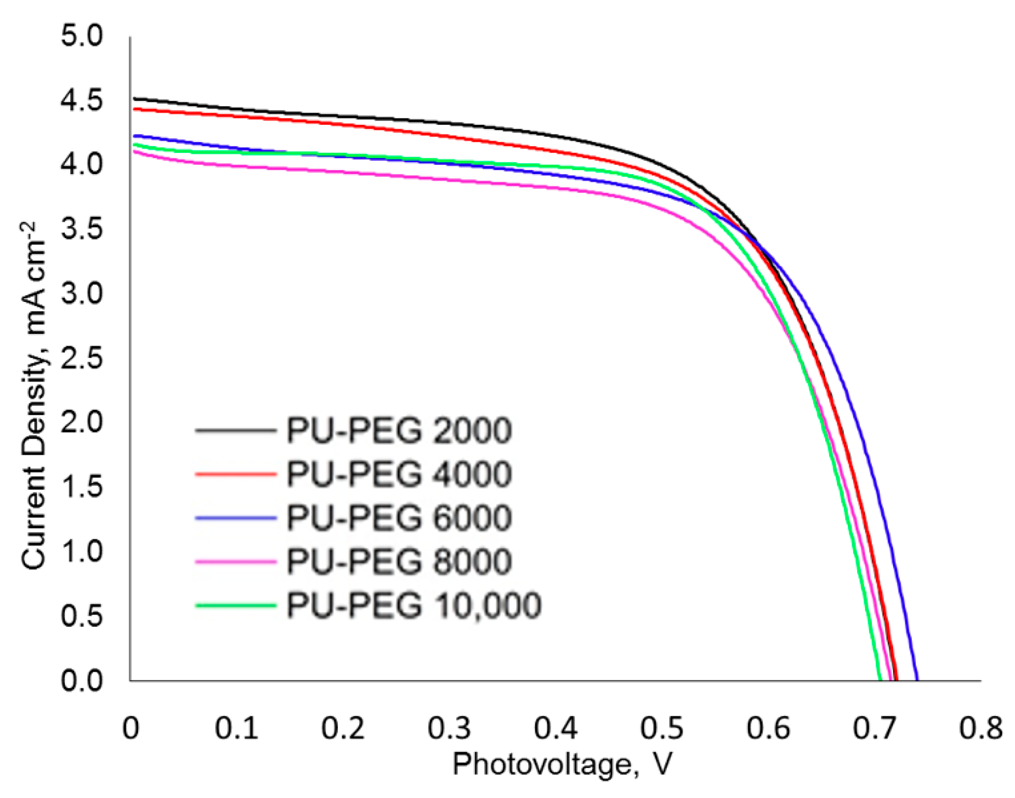
| Voc, mV | Jsc, mAcm−2 | FF | Ƞ (%) | |
|---|---|---|---|---|
| PU−PEG 2000 | 720 ± 04 | 4.52 ± 0.11 | 0.63 ± 0.02 | 3.41 ± 0.15 |
| PU−PEG 4000 | 721 ± 06 | 4.41 ± 0.16 | 0.63 ± 0.01 | 3.33 ± 0.18 |
| PU−PEG 6000 | 715 ± 12 | 4.24 ± 0.09 | 0.63 ± 0.01 | 3.18 ± 0.16 |
| PU−PEG 8000 | 716 ± 05 | 4.13 ± 0.06 | 0.63 ± 0.01 | 3.11 ± 0.10 |
| PU−PEG 10,000 | 708 ± 10 | 4.13 ± 0.14 | 0.65 ± 0.02 | 3.17 ± 0.16 |
Publisher’s Note: MDPI stays neutral with regard to jurisdictional claims in published maps and institutional affiliations. |
© 2022 by the authors. Licensee MDPI, Basel, Switzerland. This article is an open access article distributed under the terms and conditions of the Creative Commons Attribution (CC BY) license (https://creativecommons.org/licenses/by/4.0/).
Share and Cite
Sing Liow, K.; Sipaut, C.S.; Fran Mansa, R.; Ching Ung, M.; Ebrahimi, S. Effect of PEG Molecular Weight on the Polyurethane-Based Quasi-Solid-State Electrolyte for Dye-Sensitized Solar Cells. Polymers 2022, 14, 3603. https://doi.org/10.3390/polym14173603
Sing Liow K, Sipaut CS, Fran Mansa R, Ching Ung M, Ebrahimi S. Effect of PEG Molecular Weight on the Polyurethane-Based Quasi-Solid-State Electrolyte for Dye-Sensitized Solar Cells. Polymers. 2022; 14(17):3603. https://doi.org/10.3390/polym14173603
Chicago/Turabian StyleSing Liow, Kai, Coswald Stephen Sipaut, Rachel Fran Mansa, Mee Ching Ung, and Shamsi Ebrahimi. 2022. "Effect of PEG Molecular Weight on the Polyurethane-Based Quasi-Solid-State Electrolyte for Dye-Sensitized Solar Cells" Polymers 14, no. 17: 3603. https://doi.org/10.3390/polym14173603
APA StyleSing Liow, K., Sipaut, C. S., Fran Mansa, R., Ching Ung, M., & Ebrahimi, S. (2022). Effect of PEG Molecular Weight on the Polyurethane-Based Quasi-Solid-State Electrolyte for Dye-Sensitized Solar Cells. Polymers, 14(17), 3603. https://doi.org/10.3390/polym14173603