
Bamboo Charcoal/Poly(L-lactide) Fiber Webs Prepared Using Laser-Heated Melt Electrospinning

 and
and
Abstract
:1. Introduction
2. Materials and Methods
2.1. Materials
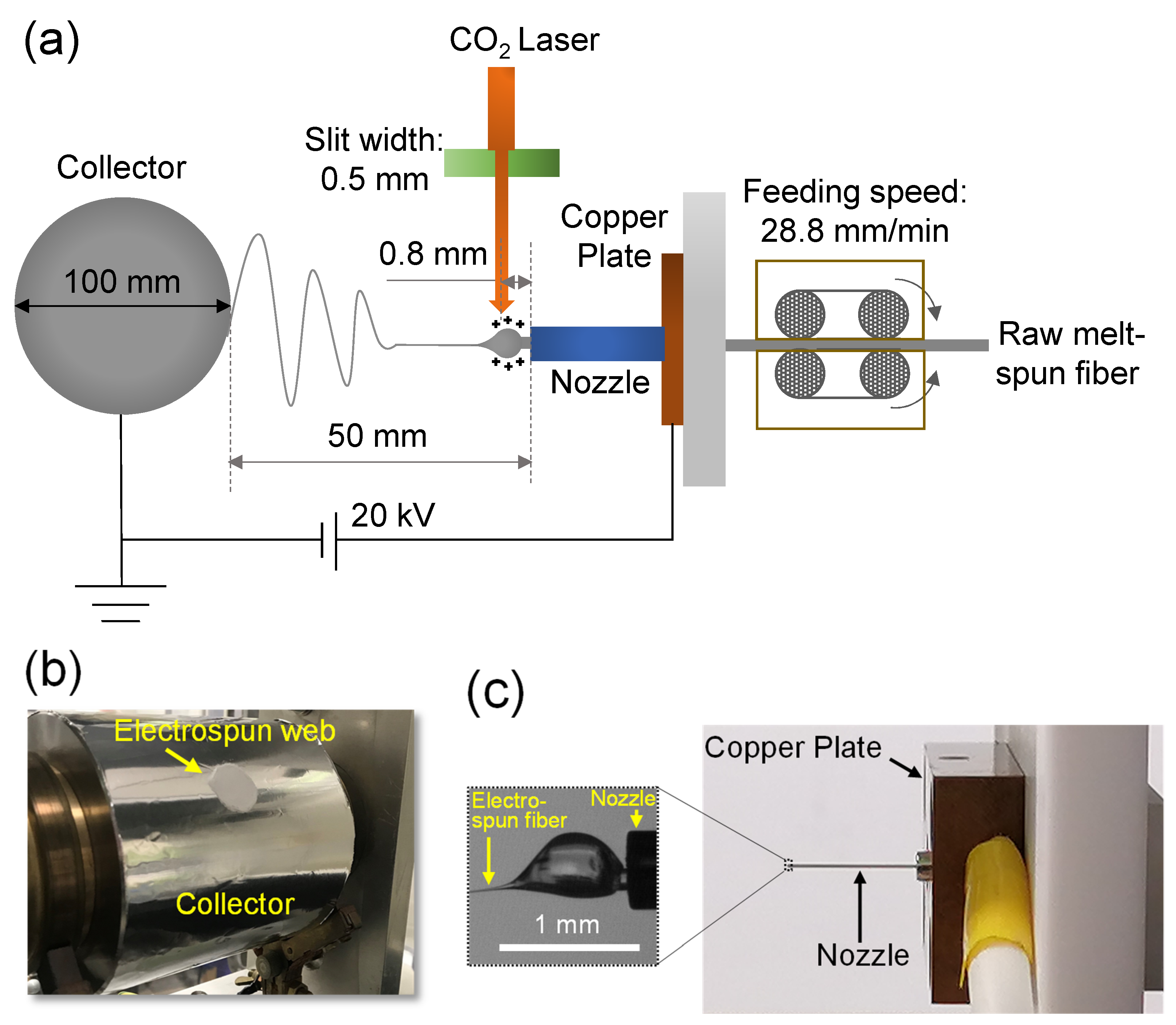
2.2. LES
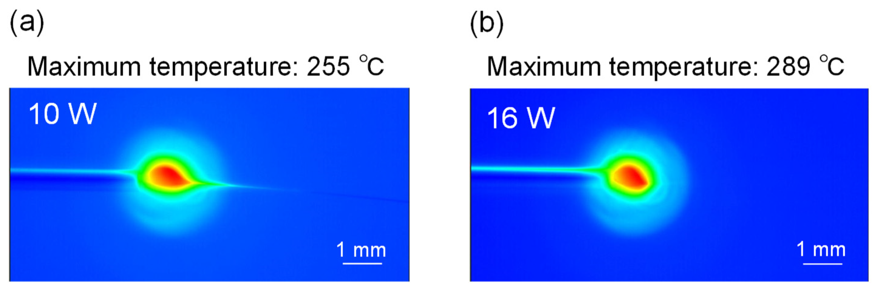
2.3. Fiber Temperature Measurement Using Thermography during LES
2.4. Preparation of Film Samples
2.5. Fourier Transform Infrared (FTIR) Spectroscopy
2.6. SEM
2.7. Temperature-Modulated Differential Scanning Calorimetry (TMDSC)
2.8. WAXD
2.9. Ultraviolet-Visible (UV-Vis) Spectroscopy
2.10. Polarizing Microscope
3. Results and Discussion
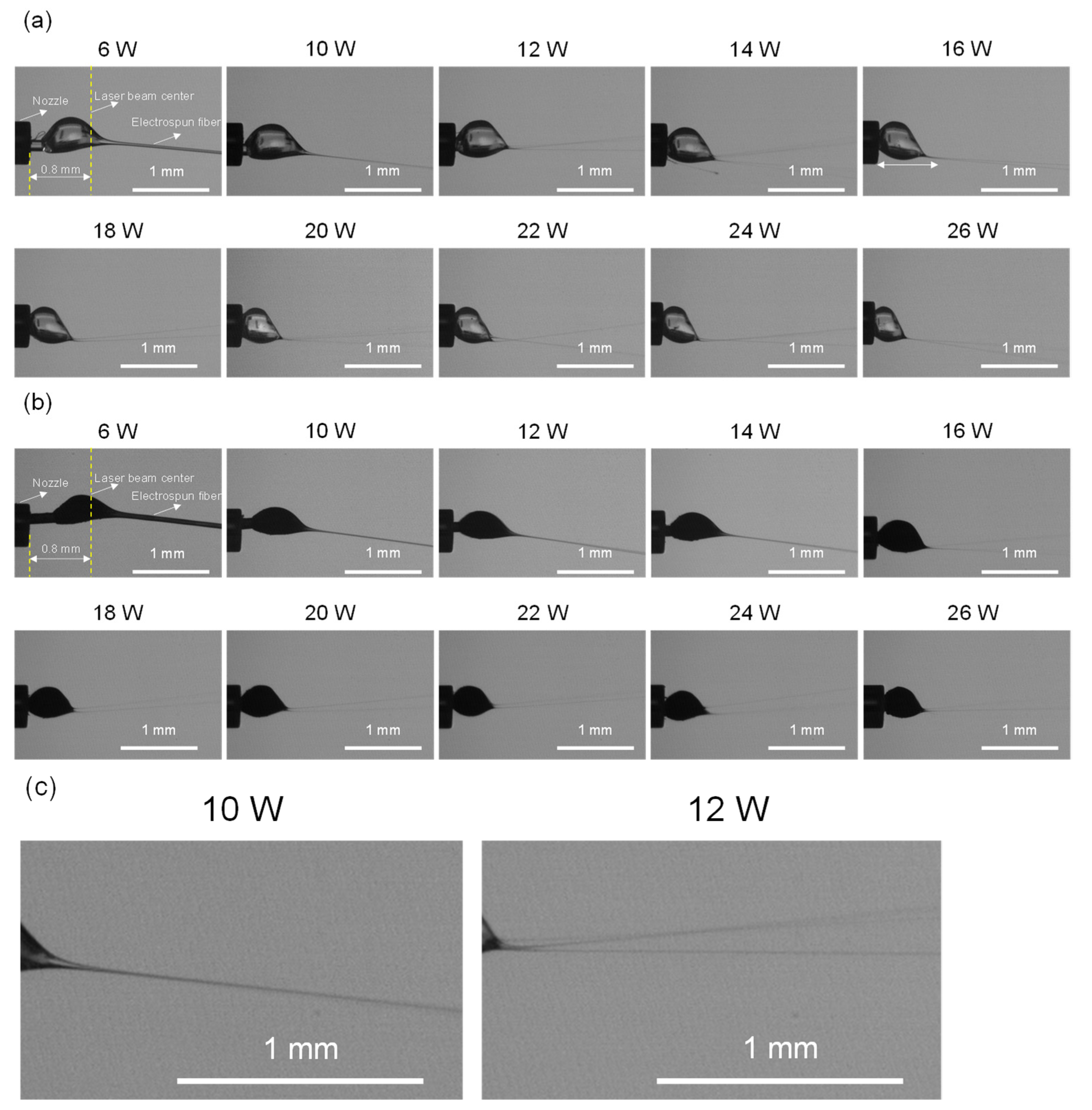
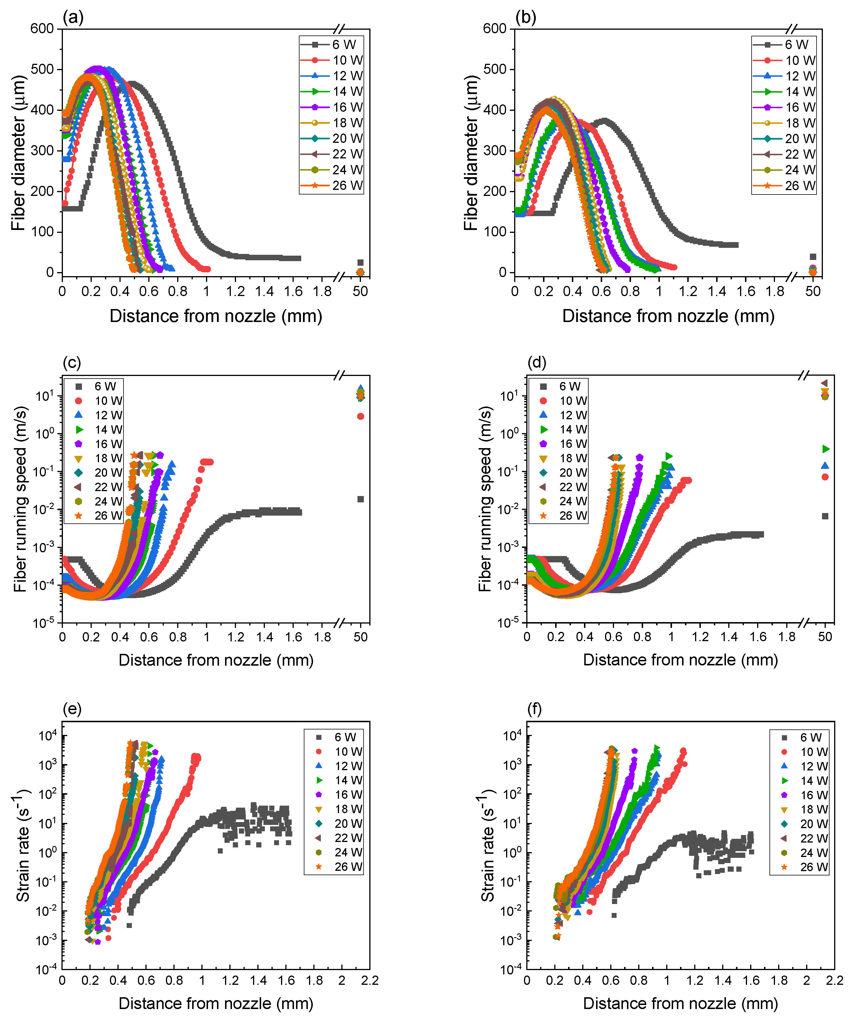
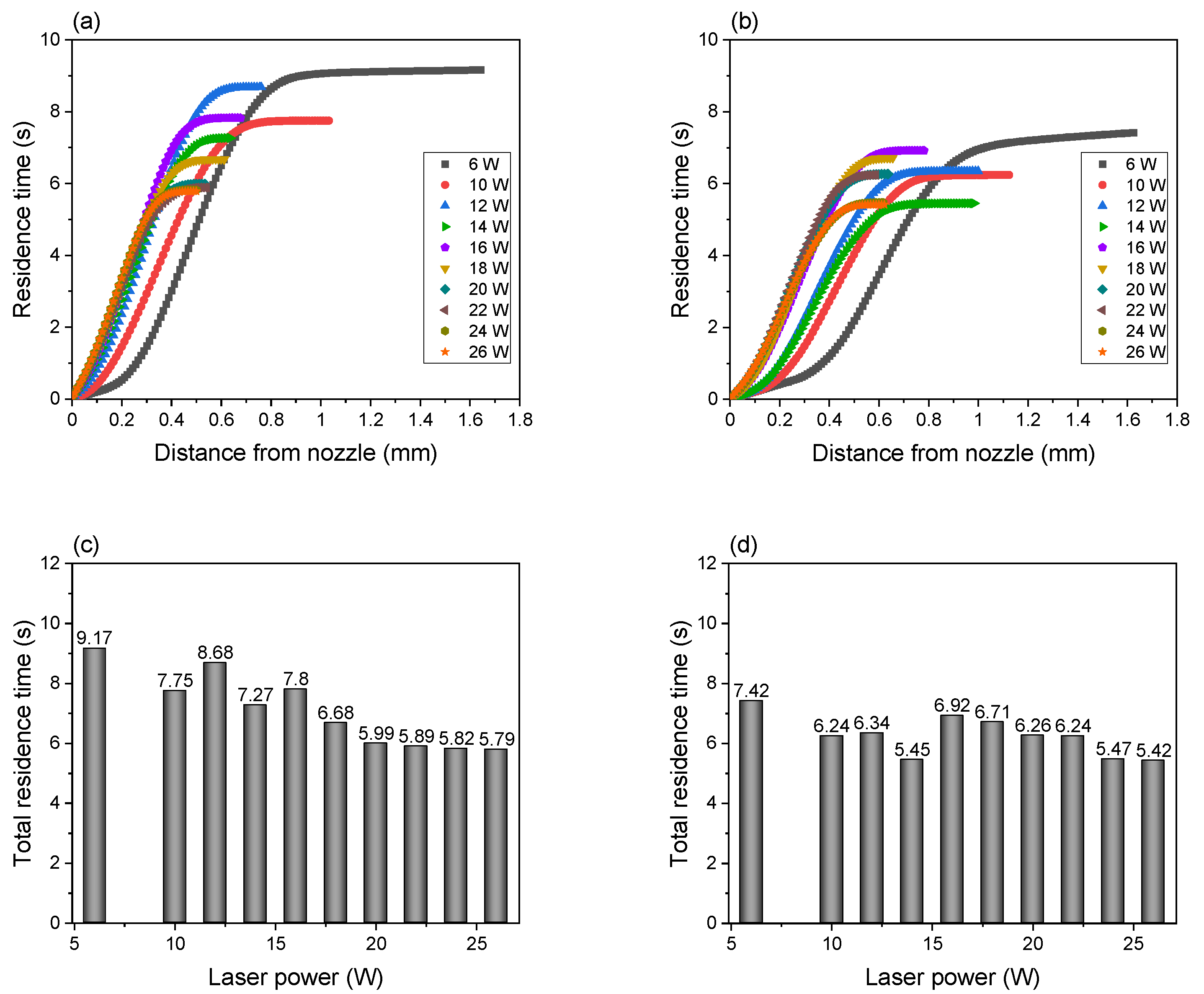
3.1. Thinning Behavior of the Fiber near the Nozzle during LES
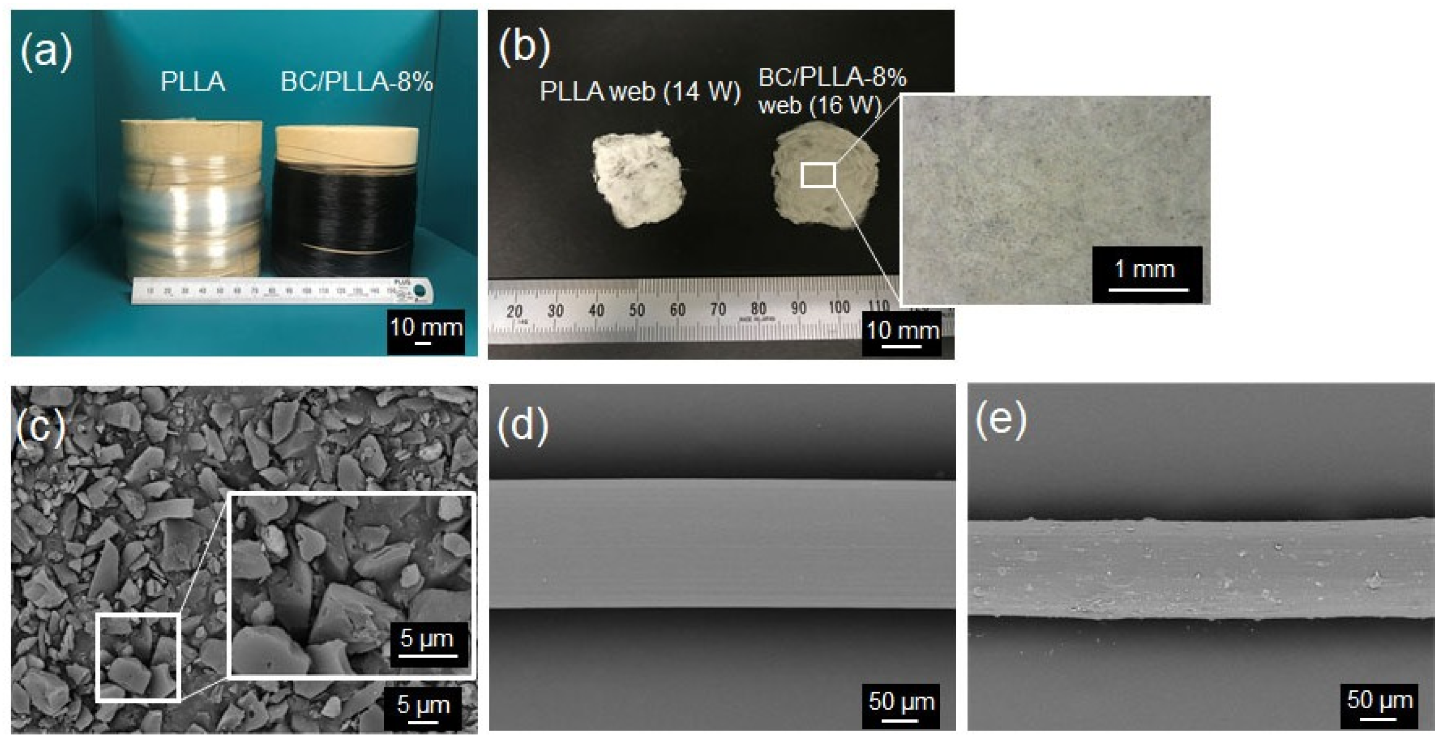
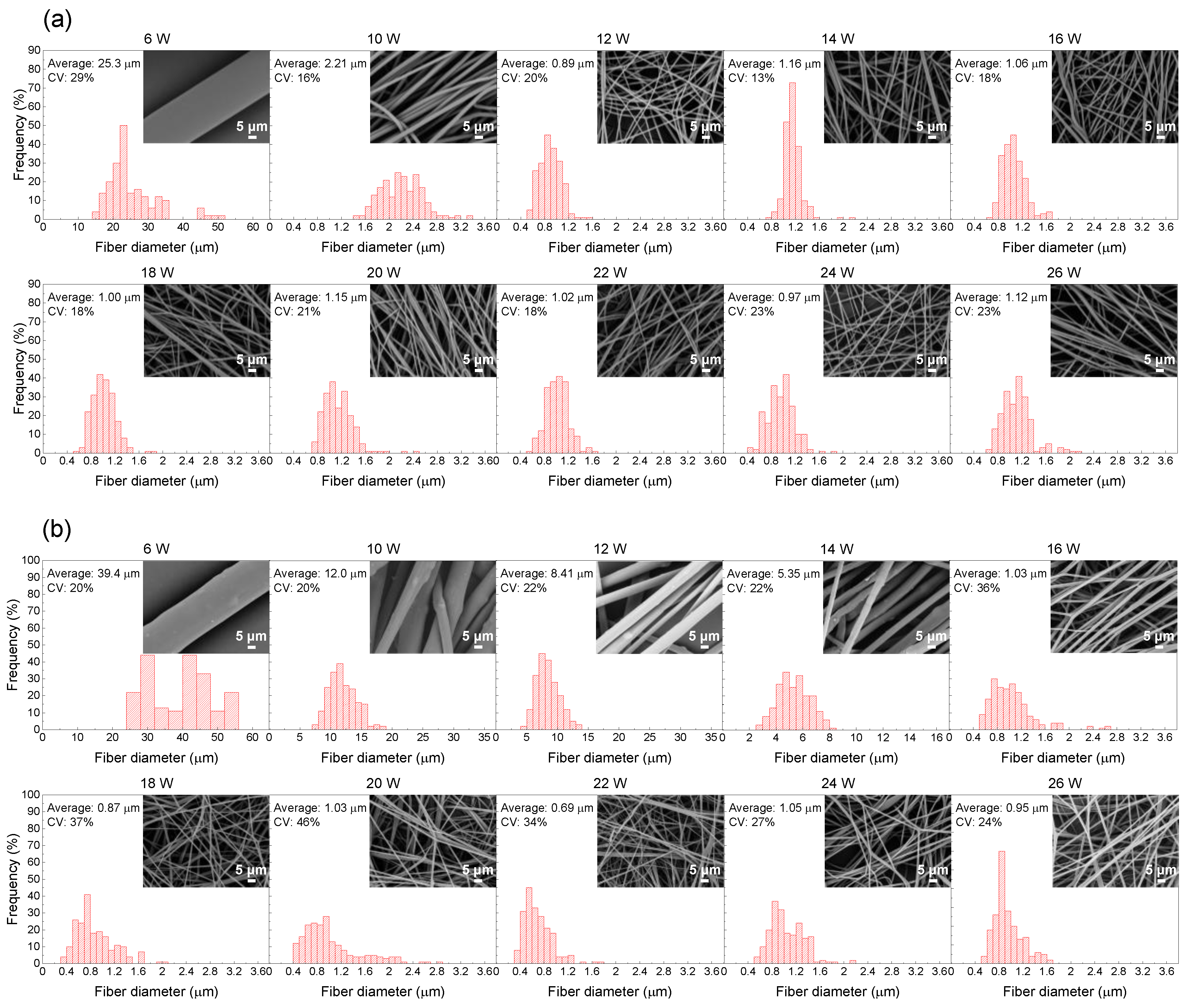
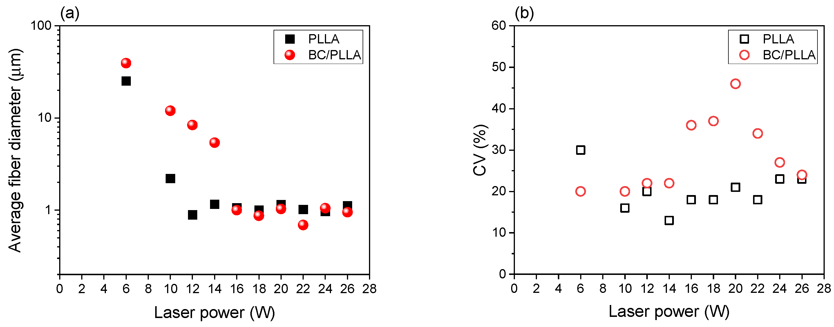
3.2. Morphologies and Diameter of Fiber Samples
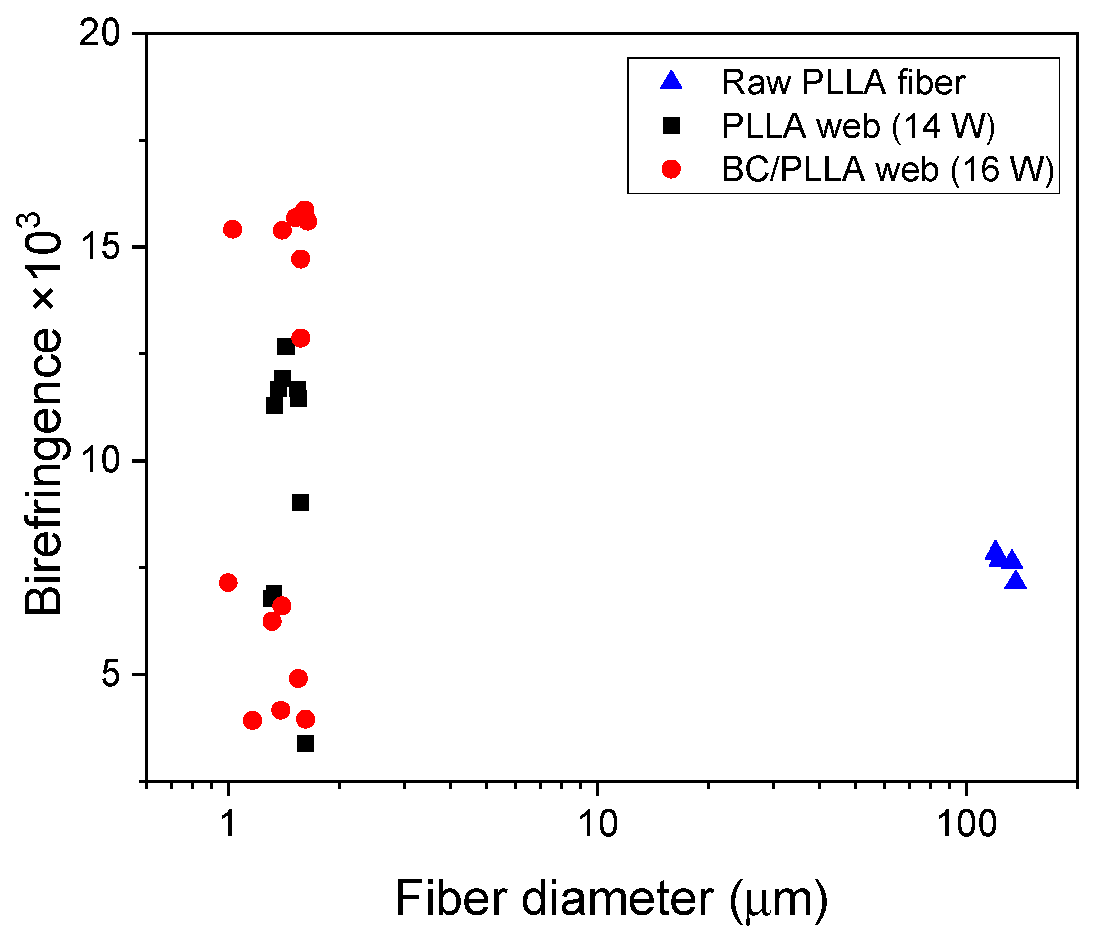
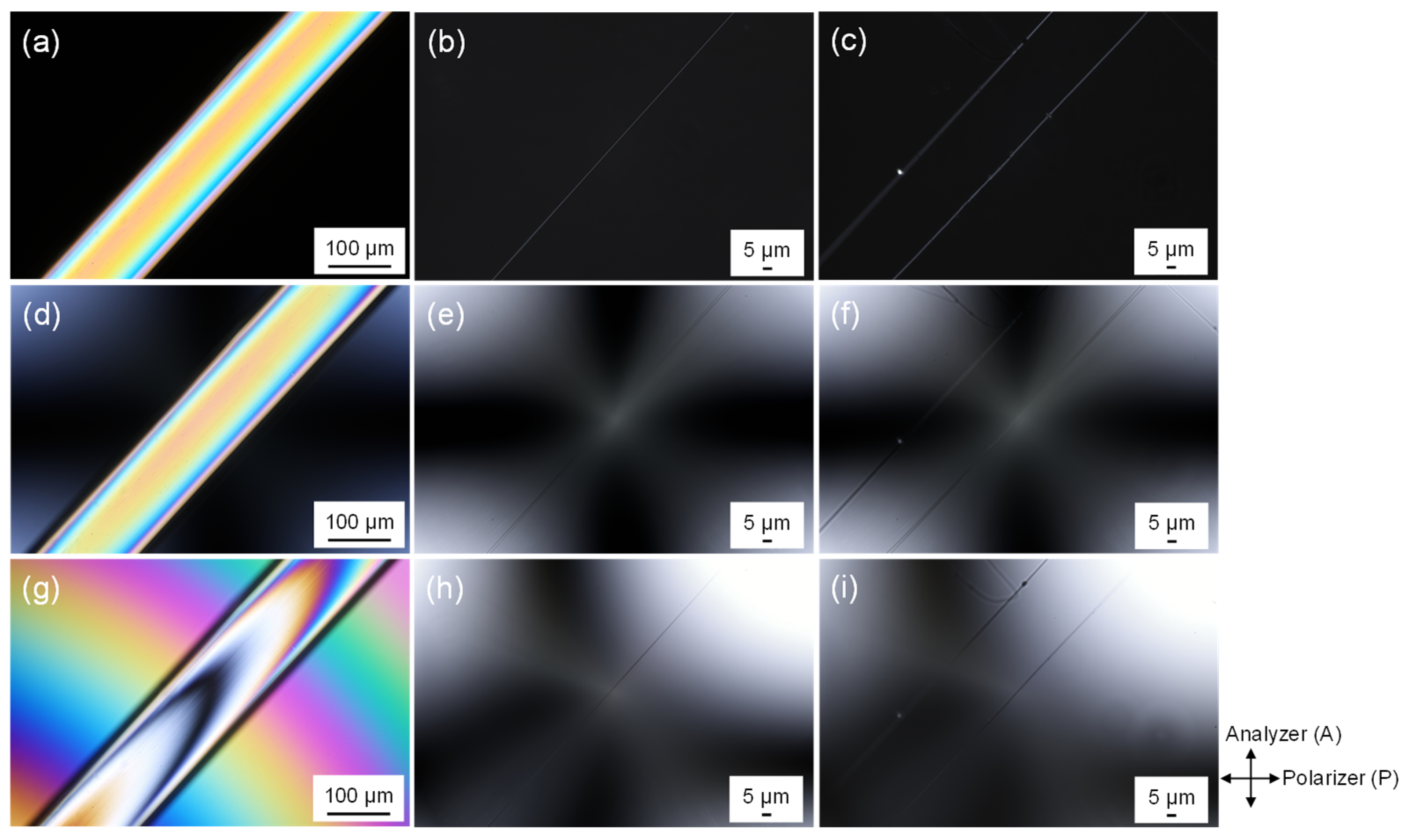
3.3. Birefringence Analysis
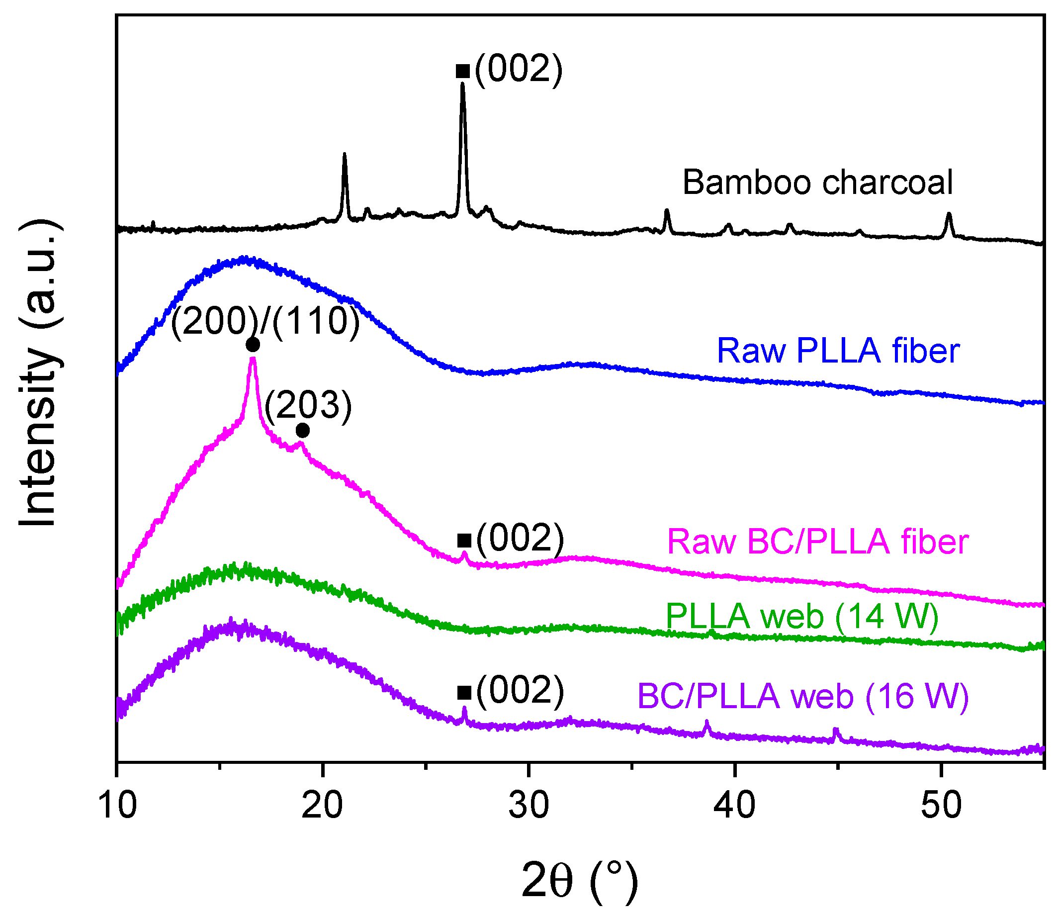
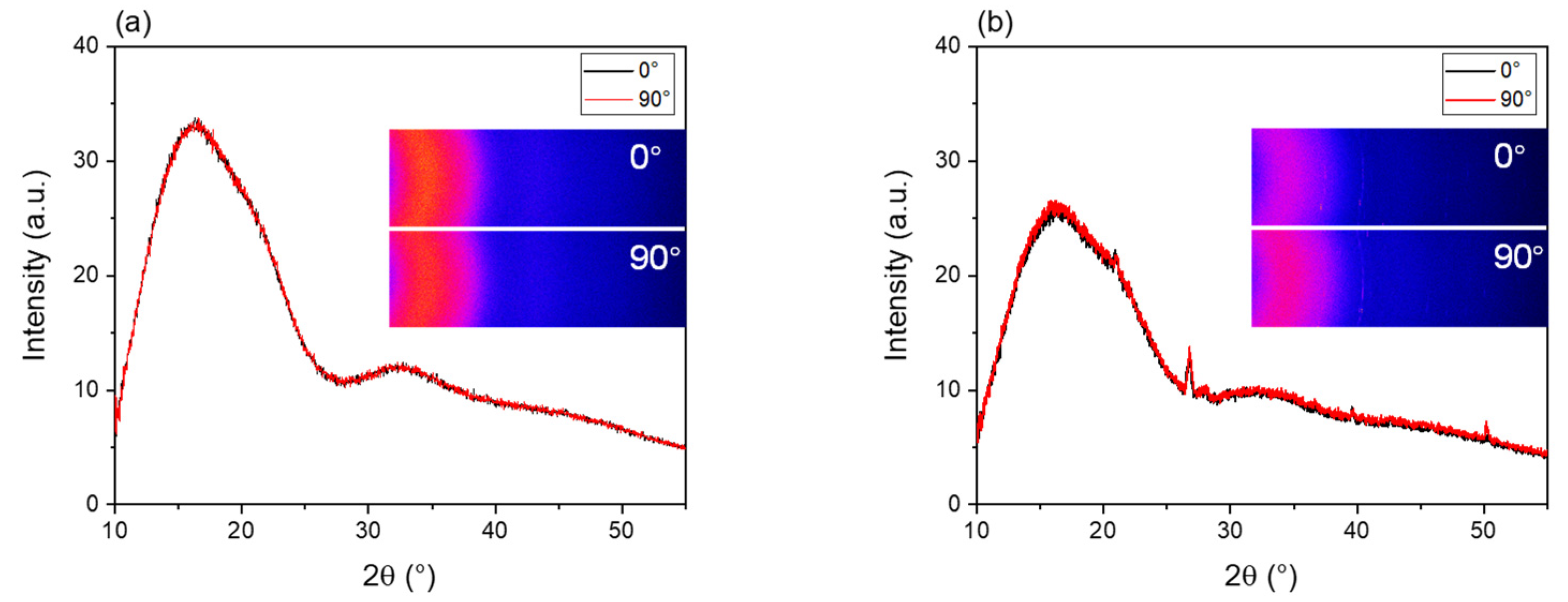
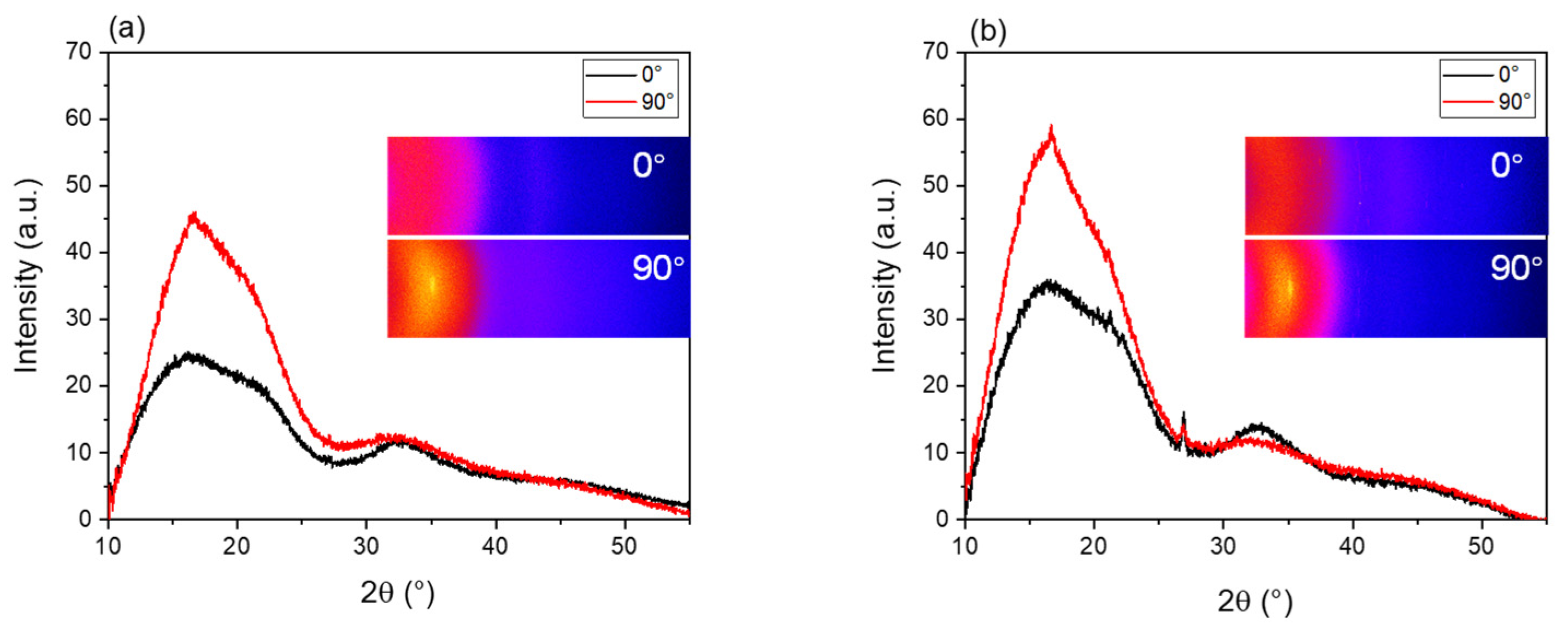
3.4. WAXD Analysis
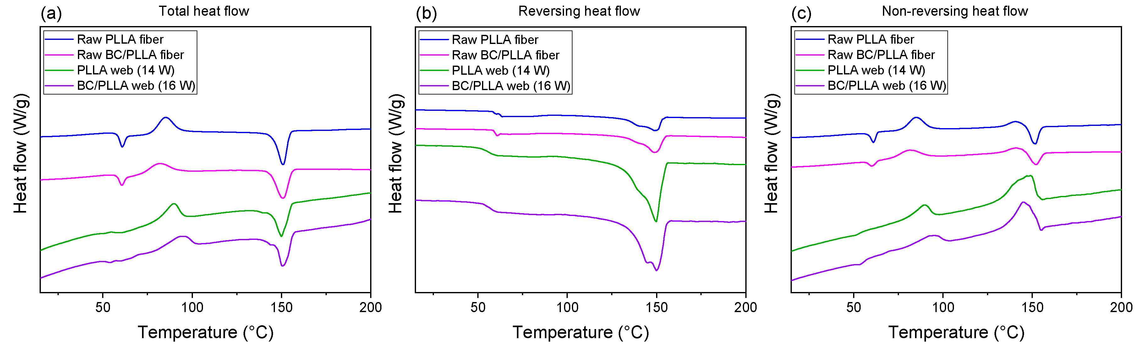
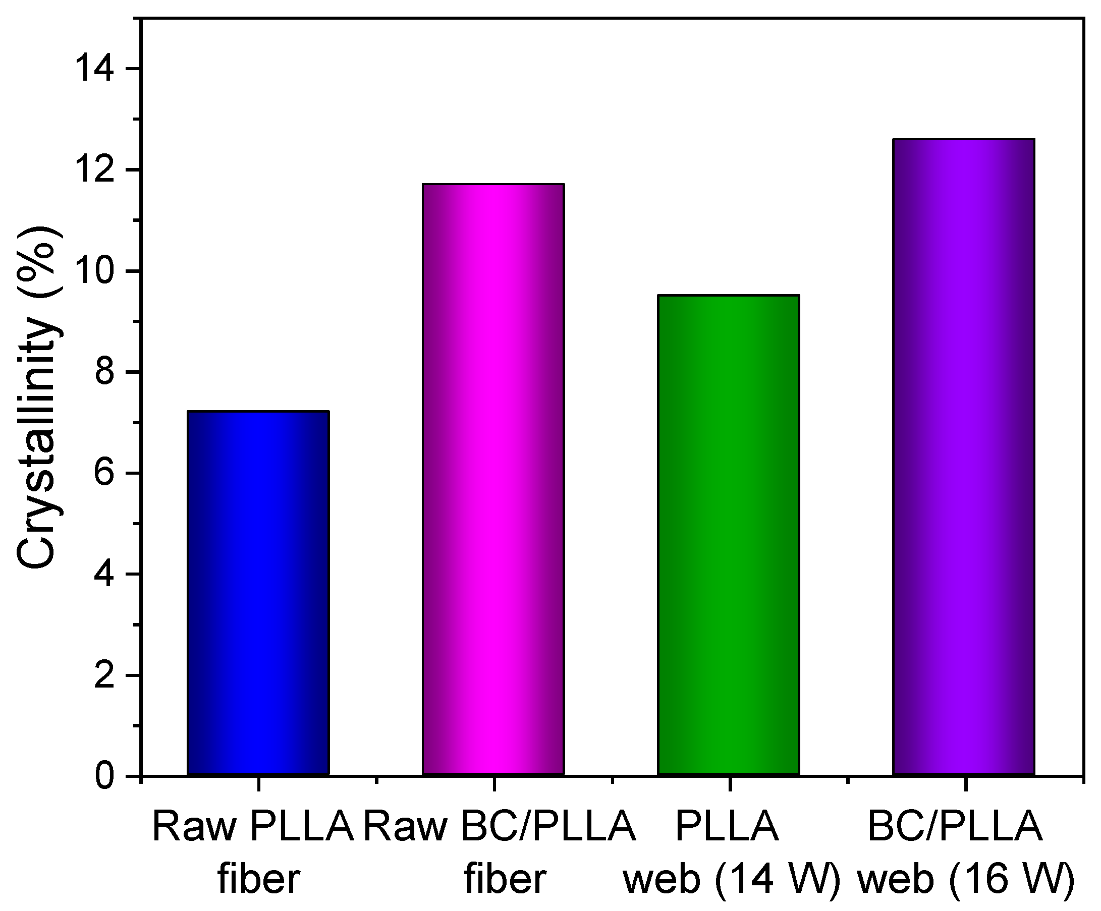
3.5. TMDSC
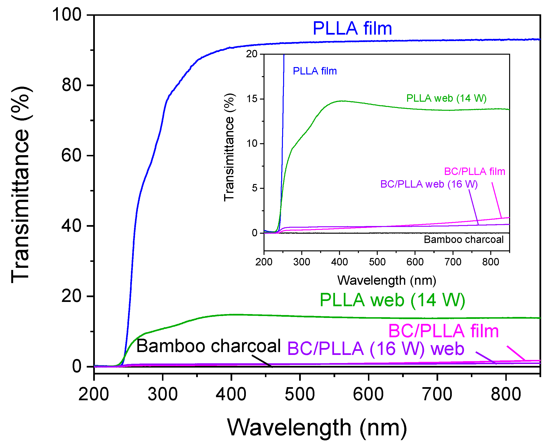
3.6. UV-Vis Shielding
4. Conclusions
Author Contributions
Funding
Institutional Review Board Statement
Informed Consent Statement
Data Availability Statement
Acknowledgments
Conflicts of Interest
Nomenclature
| Fiber running speed in the spinline (m/s) | |
| Feeding speed of the raw melt-spun fiber (m/s) | |
| Diameter in the spinline (m) | |
| Diameter of the raw melt-spun fiber (m) | |
| Strain rate (s−1) | |
| Distance from the nozzle (mm) | |
| Residence time (s) | |
| Absorbances | |
| Absorption coefficient (m−1) | |
| Transmittance | |
| Thickness of the film (m) | |
| Effect of the surface reflection | |
| Birefringence | |
| Optical retardation (nm) | |
| Fiber diameter (μm) |
References
- Park, J.H.; Rutledge, G.C. Ultrafine high performance polyethylene fibers. J. Mater. Sci. 2018, 53, 3049–3063. [Google Scholar] [CrossRef] [Green Version]
- Zhang, Z.; Ji, D.; He, H.; Ramakrishna, S. Electrospun ultrafine fibers for advanced face masks. Mater. Sci. Eng. R Rep. 2021, 143, 100594. [Google Scholar] [CrossRef]
- Balakrishnan, N.K.; Koenig, K.; Seide, G. The effect of dye and pigment concentrations on the diameter of melt-electrospun polylactic acid fibers. Polymers 2020, 12, 2321. [Google Scholar] [CrossRef] [PubMed]
- Yu, Y.; Xiong, S.; Huang, H.; Zhao, L.; Nie, K.; Chen, S.; Xu, J.; Yin, X.; Wang, H.; Wang, L. Fabrication and application of poly (phenylene sulfide) ultrafine fiber. React. Funct. Polym. 2020, 150, 104539. [Google Scholar] [CrossRef]
- Iordanskii, A.; Karpova, S.; Olkhov, A.; Borovikov, P.; Kildeeva, N.; Liu, Y. Structure-morphology impact upon segmental dynamics and diffusion in the biodegradable ultrafine fibers of polyhydroxybutyrate-polylactide blends. Eur. Polym. J. 2019, 117, 208–216. [Google Scholar] [CrossRef]
- Zapletalova, T.; Michielsen, S.; Pourdeyhimi, B. Polyether based thermoplastic polyurethane melt blown nonwovens. J. Eng. Fibers Fabr. 2006, 1, 62–72. [Google Scholar] [CrossRef] [Green Version]
- Zhang, X.; Lu, Y. Centrifugal spinning: An alternative approach to fabricate nanofibers at high speed and low cost. Polym. Rev. 2014, 54, 677–701. [Google Scholar] [CrossRef]
- Weitz, R.T.; Harnau, L.; Rauschenbach, S.; Burghard, M.; Kern, K. Polymer nanofibers via nozzle-free centrifugal spinning. Nano Lett. 2008, 8, 1187–1191. [Google Scholar] [CrossRef] [Green Version]
- Xue, J.; Wu, T.; Dai, Y.; Xia, Y. Electrospinning and electrospun nanofibers: Methods, materials, and applications. Chem. Rev. 2019, 119, 5298–5415. [Google Scholar] [CrossRef]
- Takasaki, M.; Nakashima, K.; Tsuruda, R.; Tokuda, Y.; Tanaka, K.; Kobayashi, H. Drug release behavior of a drug-loaded polylactide nanofiber web prepared via laser-electrospinning. J. Macromol. Sci. B. 2019, 58, 592–602. [Google Scholar] [CrossRef]
- Wang, Y.B.; Tian, L.; Zhu, T.H.; Mei, J.; Chen, Z.Z.; Yu, D.G. Electrospun aspirin/Eudragit/lipid hybrid nanofibers for colon-targeted delivery using an energy-saving process. Chem. Res. Chin. Univ. 2021, 37, 443–449. [Google Scholar] [CrossRef] [PubMed]
- Ponnamma, D.; Chamakh, M.M.; Alahzm, A.M.; Salim, N.; Hameed, N.; AlMaadeed, M.A.A. Core-shell nanofibers of polyvinylidene fluoride-based nanocomposites as piezoelectric nanogenerators. Polymers 2020, 12, 2344. [Google Scholar] [CrossRef] [PubMed]
- Wang, M.L.; Li, D.; Li, J.; Li, S.Y.; Chen, Z.; Yu, D.G.; Liu, Z.P.; Guo, Z.H. Electrospun Janus zein–PVP nanofibers provide a two-stage controlled release of poorly water-soluble drugs. Mater. Des. 2020, 196, 109075. [Google Scholar] [CrossRef]
- Ding, Y.F.; Dou, C.H.; Chang, S.Y.; Xie, Z.M.; Yu, D.G.; Liu, Y.N.; Shao, J. Core–shell eudragit s100 nanofibers prepared via triaxial electrospinning to provide a colon-targeted extended drug release. Polymers 2020, 12, 2034. [Google Scholar] [CrossRef]
- Aidana, Y.; Wang, Y.; Li, J.; Chang, S.; Wang, K.; Yu, D.G. Fast dissolution electrospun medicated nanofibers for effective delivery of poorly water-soluble drugs. Curr. Drug Deliv. 2021, 18. [Google Scholar] [CrossRef]
- Ostheller, M.E.; Balakrishnan, N.K.; Groten, R.; Seide, G. Detailed process analysis of biobased polybutylene succinate microfibers produced by laboratory-scale melt electrospinning. Polymers 2021, 13, 1024. [Google Scholar] [CrossRef]
- Kang, S.X.; Hou, S.C.; Chen, X.W.; Yu, D.G.; Wang, L.; Li, X.Y.; Williams, G.R. Energy-saving electrospinning with a concentric teflon-core rod spinneret to create medicated nanofibers. Polymers 2020, 12, 2421. [Google Scholar] [CrossRef]
- King, W.E.; Bowlin, G.L. Near-field electrospinning and melt electrowriting of biomedical polymers—Progress and limitations. Polymers 2021, 13, 1097. [Google Scholar] [CrossRef]
- Li, X.; Liu, H.; Wang, J.; Li, C. Preparation and characterization of PLLA/nHA nonwoven mats via laser melt electrospinning. Mater. Lett. 2012, 73, 103–106. [Google Scholar] [CrossRef]
- Takasaki, M.; Sugihara, K.; Ohkoshi, Y.; Fujii, T.; Shimizu, H.; Saito, M. Thermoplastic polyurethane ultrafine fiber web fabricated by laser electrospinning. Sen’i Gakkaishi 2010, 66, 168–173. [Google Scholar] [CrossRef] [Green Version]
- Tokuda, T.; Tsuruda, R.; Hara, T.; Kobayashi, H.; Tanaka, K.; Takarada, W.; Kikutani, T.; Hinestroza, J.P.; Razal, J.M.; Takasaki, M. Structure and Properties of Poly (ethylene terephthalate) Fiber Webs Prepared via Laser-Electrospinning and Subsequent Annealing Processes. Materials 2020, 13, 5783. [Google Scholar] [CrossRef]
- Lizundia, E.; Vilas, J.L.; Sangroniz, A.; Etxeberria, A. Light and gas barrier properties of PLLA/metallic nanoparticles composite films. Eur. Polym. J. 2017, 91, 10–20. [Google Scholar] [CrossRef]
- Wang, D.Y.; Song, Y.P.; Lin, L.; Wang, X.L.; Wang, Y.Z. A novel phosphorus-containing poly (lactic acid) toward its flame retardation. Polymer 2011, 52, 233–238. [Google Scholar] [CrossRef]
- Tertyshnaya, Y.; Podzorova, M.; Moskovskiy, M. Impact of Water and UV Irradiation on Nonwoven Polylactide/Natural Rubber Fiber. Polymers 2021, 13, 461. [Google Scholar] [CrossRef]
- Zhou, H.; Green, T.B.; Joo, Y.L. The thermal effects on electrospinning of polylactic acid melts. Polymer 2006, 47, 7497–7505. [Google Scholar] [CrossRef]
- Hong, Y.; Fujimoto, K.; Hashizume, R.; Guan, J.; Stankus, J.J.; Tobita, K.; Wagner, W.R. Generating elastic, biodegradable polyurethane/poly (lactide-co-glycolide) fibrous sheets with controlled antibiotic release via two-stream electrospinning. Biomacromolecules 2008, 9, 1200–1207. [Google Scholar] [CrossRef] [PubMed] [Green Version]
- Athanasoulia, I.G.; Giachalis, K.; Korres, D.; Todorova, N.; Giannakopoulou, T.; Tarantili, P.A.; Trapalis, C. Study of thermomechanical, structural and antibacterial properties of poly (lactic acid) reinforced with graphene oxide nanoparticles via melt mixing. Polym. Int. 2020, 69, 995–1007. [Google Scholar] [CrossRef]
- Ho, M.; Lau, K.; Wang, H.; Hui, D. Improvement on the properties of polylactic acid (PLA) using bamboo charcoal particles. Compos. Part B Eng. 2015, 81, 14–25. [Google Scholar] [CrossRef]
- Wang, S.; Zhang, L.; Semple, K.; Zhang, M.; Zhang, W.; Dai, C. Development of Biodegradable Flame-Retardant Bamboo Charcoal Composites, Part II: Thermal Degradation, Gas Phase, and Elemental Analyses. Polymers 2020, 12, 2238. [Google Scholar] [CrossRef] [PubMed]
- Lou, C.W.; Lin, C.W.; Lei, C.H.; Su, K.H.; Hsu, C.H.; Liu, Z.H.; Lin, J.H. PET/PP blend with bamboo charcoal to produce functional composites. J. Mater. Process. Technol. 2007, 192, 428–433. [Google Scholar] [CrossRef]
- Qian, S.; Yan, W.; Zhu, S.; Fontanillo Lopez, C.A.; Sheng, K. Surface modification of bamboo-char and its reinforcement in PLA biocomposites. Polym. Compos. 2018, 39, 633–639. [Google Scholar] [CrossRef]
- Wang, S.; Zhao, L.; Zhou, H.; Li, W.; Zhang, W. Effect of Aluminum Hypophosphite on Flame Retardancy and Mechanical Property of Bamboo Charcoal/Polylactic Acid Composites. Mater. Rep. 2020, 34, 14214–14217. [Google Scholar]
- Zhu, L.; Zhou, X.; Liu, Y.H.; Fu, Q. Highly sensitive, ultrastretchable strain sensors prepared by pumping hybrid fillers of carbon nanotubes/cellulose nanocrystal into electrospun polyurethane membranes. ACS Appl. Mater. Interfaces 2019, 11, 12968–12977. [Google Scholar] [CrossRef] [PubMed]
- Haroosh, H.J.; Chaudhary, D.S.; Dong, Y. Electrospun PLA/PCL fibers with tubular nanoclay: Morphological and structural analysis. J. Appl. Polym. Sci. 2012, 124, 3930–3939. [Google Scholar] [CrossRef]
- Guo, Y.Q.; Yang, X.T.; Ruan, K.P.; Kong, J.; Dong, M.Y.; Zhang, J.X.; Gu, J.W.; Guo, Z.H. Reduced graphene oxide heterostructured silver nanoparticles significantly enhanced thermal conductivities in hot-pressed electrospun polyimide nanocomposites. ACS Appl. Mater. Inter. 2019, 11, 25465–25473. [Google Scholar] [CrossRef]
- Takasaki, M.; Kengo, M.; Ohkoshi, Y.; Hirai, T. Effects of Laser Beam Width on the Diameter and Molecular Weight of Laser-Electrospun Polylactide Fiber. Sen’i Gakkaishi 2015, 71, 232–235. [Google Scholar] [CrossRef] [Green Version]
- Zuza, E.; Ugartemendia, J.M.; Lopez, A.; Meaurio, E.; Lejardi, A.; Sarasua, J. Glass transition behavior and dynamic fragility in polylactides containing mobile and rigid amorphous fractions. Polymer 2008, 49, 4427–4432. [Google Scholar] [CrossRef]
- Andrady, A.L. Science and Technology of Polymer Nanofibers; John Wiley & Sons, Inc.: Hoboken, NJ, USA, 2008; pp. 1–26. [Google Scholar]
- Murase, H.; Yabuki, K.; Tashiro, K. Advancement of Fiber Science and Technology. In High-Performance and Specialty Fibers: Concepts, Technology and Modern Applications of Man-Made Fibers for the Future; Kikutani, T., Ed.; Springer: Tokyo, Japan, 2016; pp. 49–65. [Google Scholar]
- Wang, C.; Wang, Y.; Hashimoto, T. Impact of entanglement density on solution electrospinning: A phenomenological model for fiber diameter. Macromolecules 2016, 49, 7985–7996. [Google Scholar] [CrossRef]
- Wijnen, B.; Sanders, P.; Pearce, J.M. Improved model and experimental validation of deformation in fused filament fabrication of polylactic acid. Prog. Addit. Manuf. 2018, 3, 193–203. [Google Scholar] [CrossRef] [Green Version]
- Zhao, X.; Guerrero, F.R.; Llorca, J.; Wang, D.Y. New superefficiently flame-retardant bioplastic poly (lactic acid): Flammability, thermal decomposition behavior, and tensile properties. ACS. Sustain. Chem. Eng. 2016, 4, 202–209. [Google Scholar] [CrossRef] [Green Version]
- Hayati, I.; Bailey, A.I.; Tadros, T.F. Investigations into the mechanisms of electrohydrodynamic spraying of liquids: I. Effect of electric field and the environment on pendant drops and factors affecting the formation of stable jets and atomization. J. Colloid Interface Sci. 1987, 117, 205–221. [Google Scholar]
- Takasaki, M.; Ito, H.; Kikutani, T. Structure Development of Polylactides with Various D-lactide Contents in the High-Speed Melt Spinning Process. J. Macromol. Sci. B 2003, 42, 57–73. [Google Scholar] [CrossRef]
- Seehra, M.S.; Geddam, U.K.; Schwegler-Berry, D.; Stefaniak, A.B. Detection and quantification of 2H and 3R phases in commercial graphene-based materials. Carbon 2015, 95, 818–823. [Google Scholar] [CrossRef] [Green Version]
- Seehra, M.S.; Narang, V.; Geddam, U.K.; Stefaniak, A.B. Correlation between X-ray diffraction and Raman spectra of 16 commercial graphene-based materials and their resulting classification. Carbon 2017, 111, 380–385. [Google Scholar] [CrossRef] [Green Version]
- Zhang, J.; Tashiro, K.; Tsuji, H.; Domb, A.J. Disorder-to-order phase transition and multiple melting behavior of poly (L-lactide) investigated by simultaneous measurements of WAXD and DSC. Macromolecules 2008, 41, 1352–1357. [Google Scholar] [CrossRef]
- Murase, Y.; Nagai, A. 2-Melt spinning. In Advanced Fiber Spinning Technology; Nakajima, T., Kajiwara, K., McIntyre, J.E., Eds.; Woodhead Publishing Limited: Cambridge, UK, 1994; pp. 25–64. [Google Scholar]
- Evans, P.; Chowdhury, M.J.; Mathews, B.; Schmalzl, K.; Ayer, S.; Kiguchi, M.; Kataoka, Y. Weathering and surface protection of wood. In Handbook of Environmental Degradation of Materials; Kutz, M., Ed.; William Andrew Publishing: Norwich, UK, 2005; pp. 277–297. [Google Scholar]


| Samples | Tg Reversing (°C) | Tc (°C) | Tm1 (°C) | Tm2 (°C) | Xc (%) |
|---|---|---|---|---|---|
| Raw PLLA fiber | 59.4 | 85.3 | - | 150.5 | 7.2 |
| Raw BC/PLLA fiber | 59.7 | 82.1 | - | 150.5 | 11.7 |
| PLLA web (14 W) | 55.5 | 89.9 | 139.9 | 150.0 | 9.5 |
| BC/PLLA web (16 W) | 56.5 | 95.2 | 145.0 | 150.5 | 12.6 |
Publisher’s Note: MDPI stays neutral with regard to jurisdictional claims in published maps and institutional affiliations. |
© 2021 by the authors. Licensee MDPI, Basel, Switzerland. This article is an open access article distributed under the terms and conditions of the Creative Commons Attribution (CC BY) license (https://creativecommons.org/licenses/by/4.0/).
Share and Cite
Hou, Z.; Itagaki, N.; Kobayashi, H.; Tanaka, K.; Takarada, W.; Kikutani, T.; Takasaki, M. Bamboo Charcoal/Poly(L-lactide) Fiber Webs Prepared Using Laser-Heated Melt Electrospinning. Polymers 2021, 13, 2776. https://doi.org/10.3390/polym13162776
Hou Z, Itagaki N, Kobayashi H, Tanaka K, Takarada W, Kikutani T, Takasaki M. Bamboo Charcoal/Poly(L-lactide) Fiber Webs Prepared Using Laser-Heated Melt Electrospinning. Polymers. 2021; 13(16):2776. https://doi.org/10.3390/polym13162776
Chicago/Turabian StyleHou, Zongzi, Nahoko Itagaki, Haruki Kobayashi, Katsufumi Tanaka, Wataru Takarada, Takeshi Kikutani, and Midori Takasaki. 2021. "Bamboo Charcoal/Poly(L-lactide) Fiber Webs Prepared Using Laser-Heated Melt Electrospinning" Polymers 13, no. 16: 2776. https://doi.org/10.3390/polym13162776
APA StyleHou, Z., Itagaki, N., Kobayashi, H., Tanaka, K., Takarada, W., Kikutani, T., & Takasaki, M. (2021). Bamboo Charcoal/Poly(L-lactide) Fiber Webs Prepared Using Laser-Heated Melt Electrospinning. Polymers, 13(16), 2776. https://doi.org/10.3390/polym13162776