
Exploring the Functional Properties of Sodium Phytate Doped Polyaniline Nanofibers Modified FTO Electrodes for High-Performance Binder Free Symmetric Supercapacitors

 ,
,  , ,
, ,  and
and
Abstract
:1. Introduction
2. Materials and Methods
2.1. Materials and Synthesis
2.2. Synthesis of Sodium Phytate Doped PANI
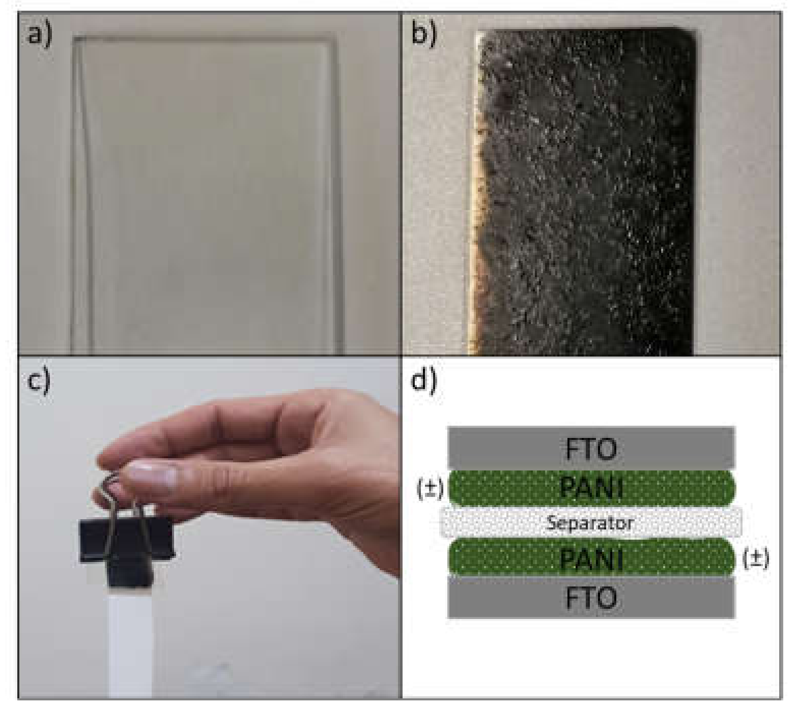
2.3. Fabrication of Working Electrode
2.4. Fabrication of FTO-PANI Supercapacitor Device
2.5. Characterization
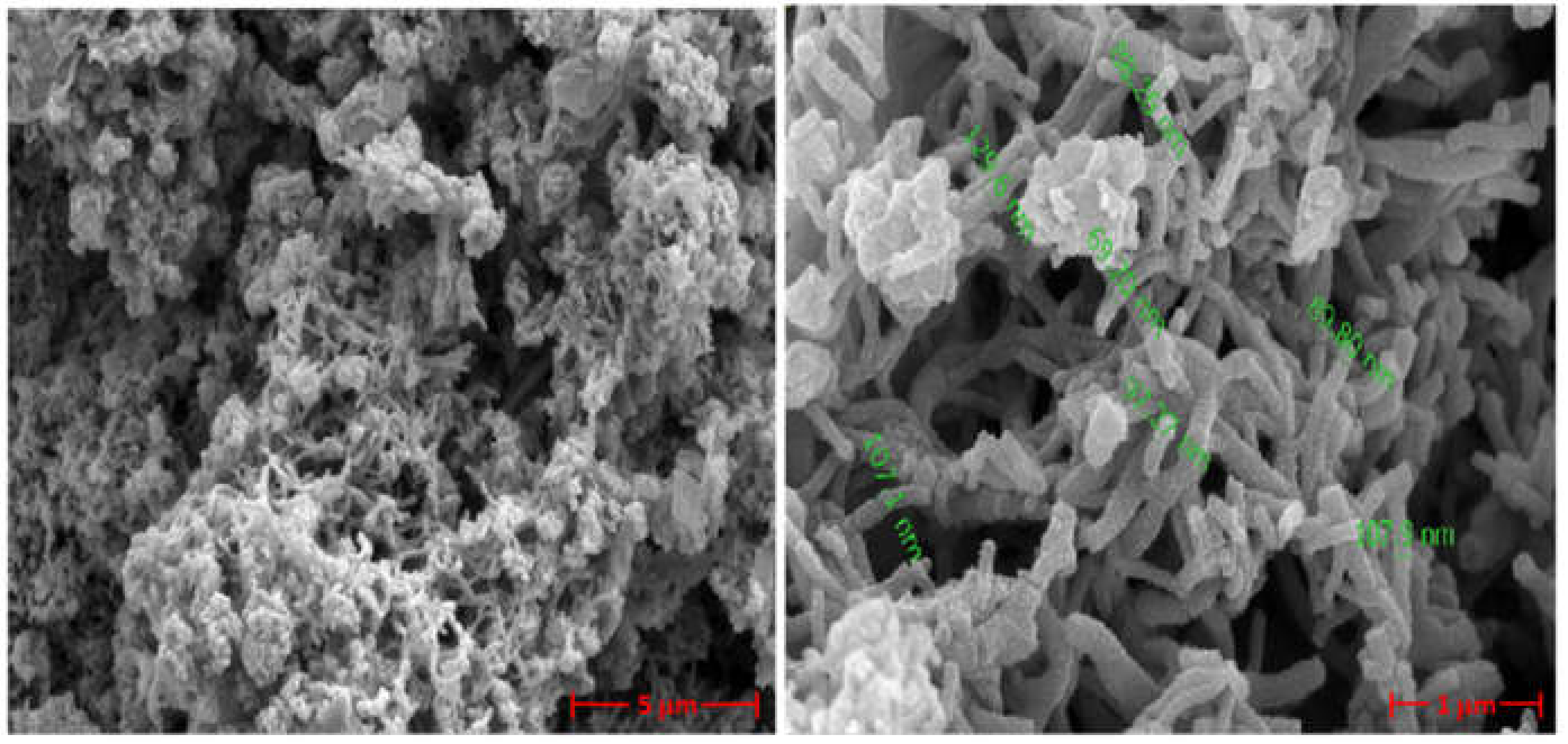
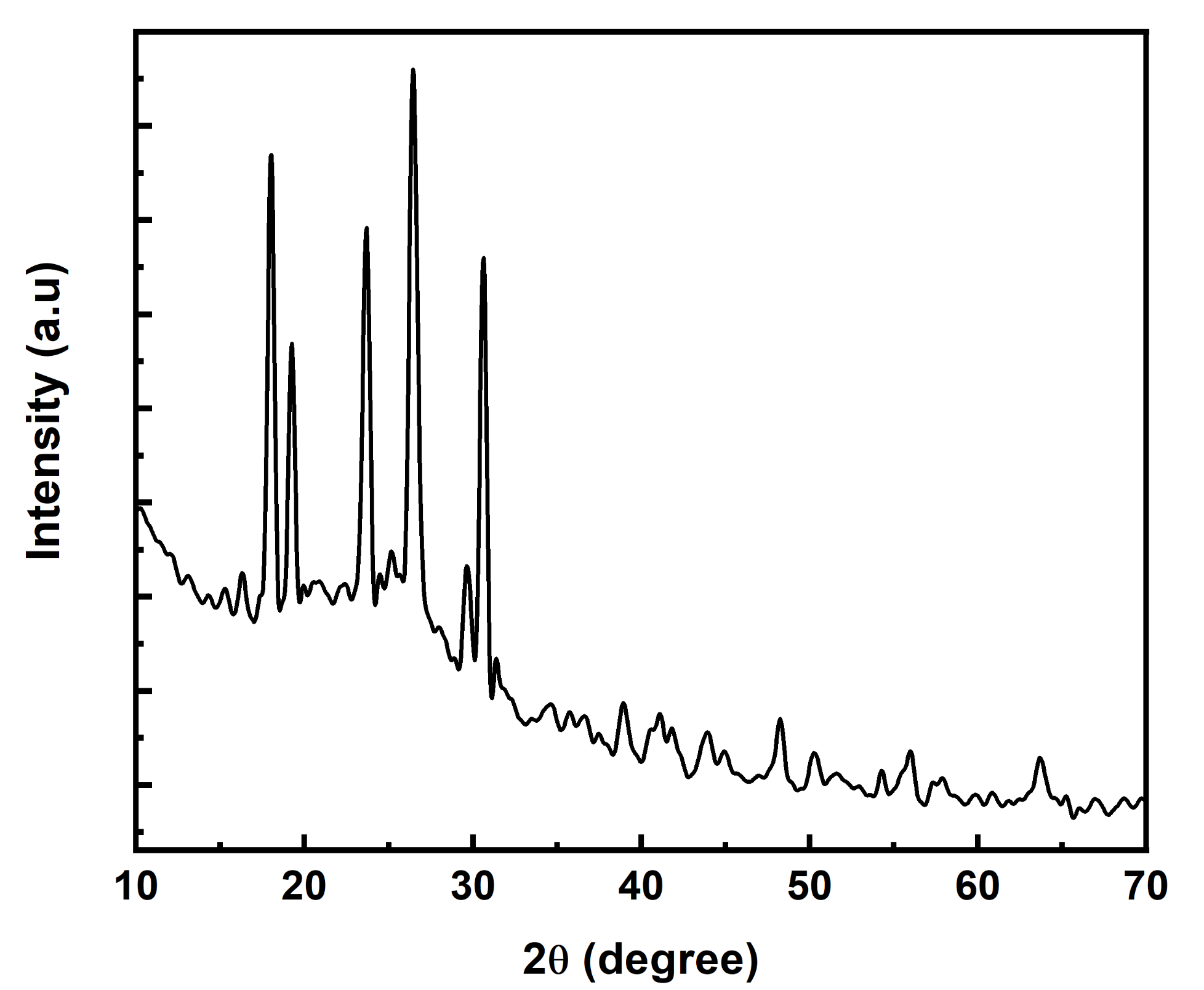
2.5.1. Structural and Morphological Characterization
2.5.2. Electrochemical Characterizations
3. Results and Discussion
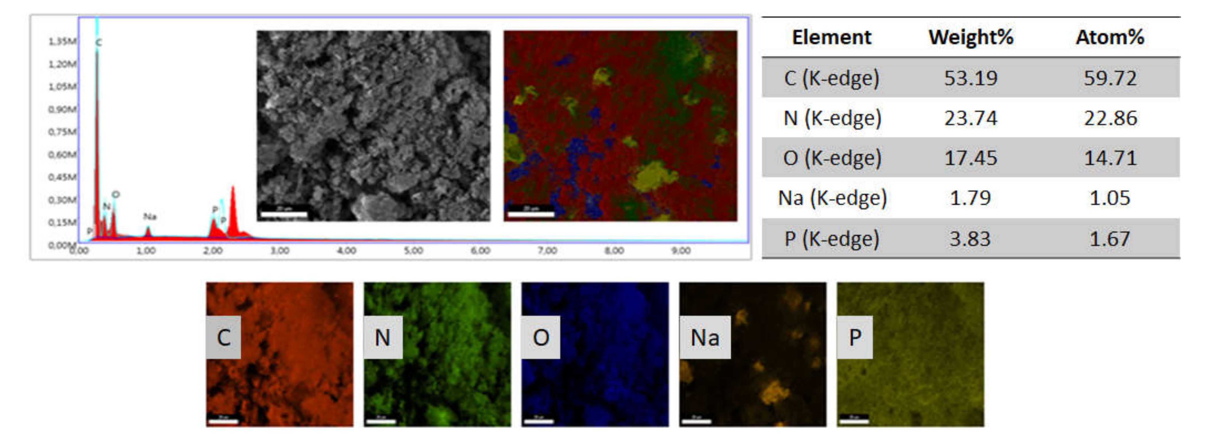
3.1. Structural and Morphological Characterization
3.2. Electrochemical Characterization
3.2.1. Electrical Conductivity
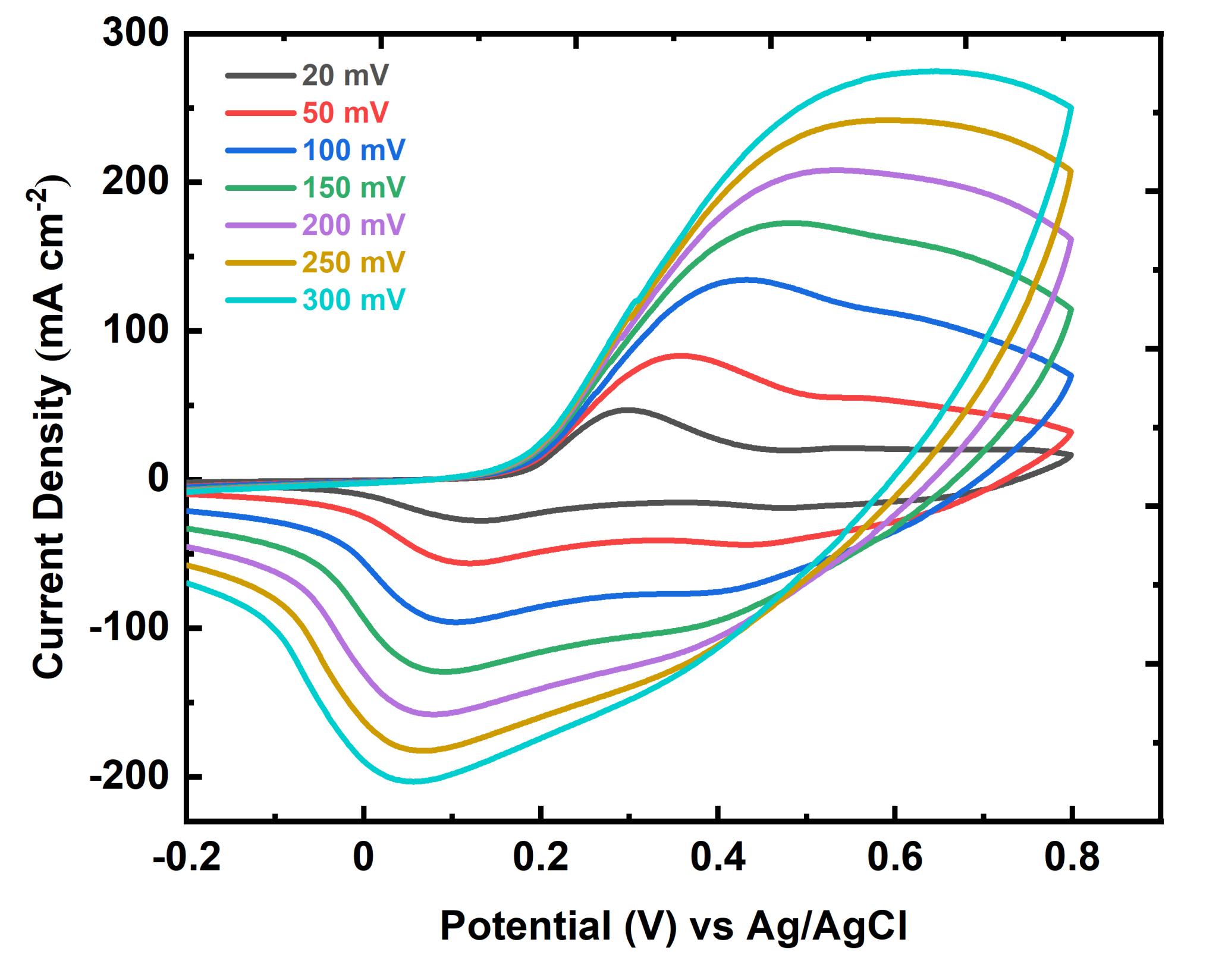
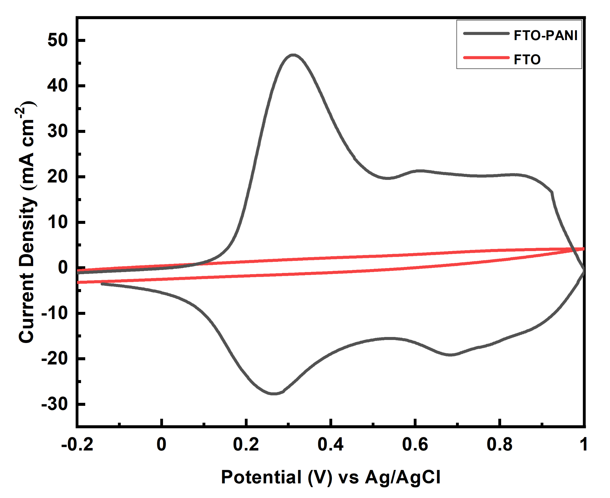
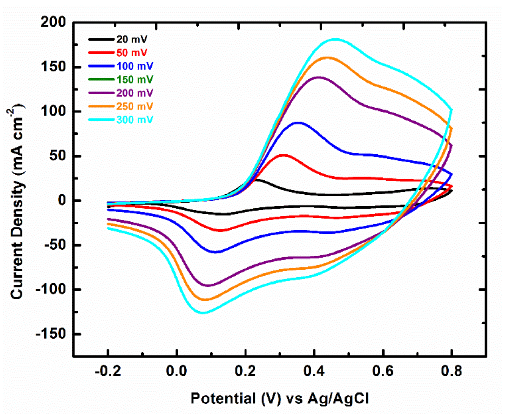
3.2.2. Cyclic Voltammetry (CV)
3.2.3. Fabrication of Symmetric Supercapacitor
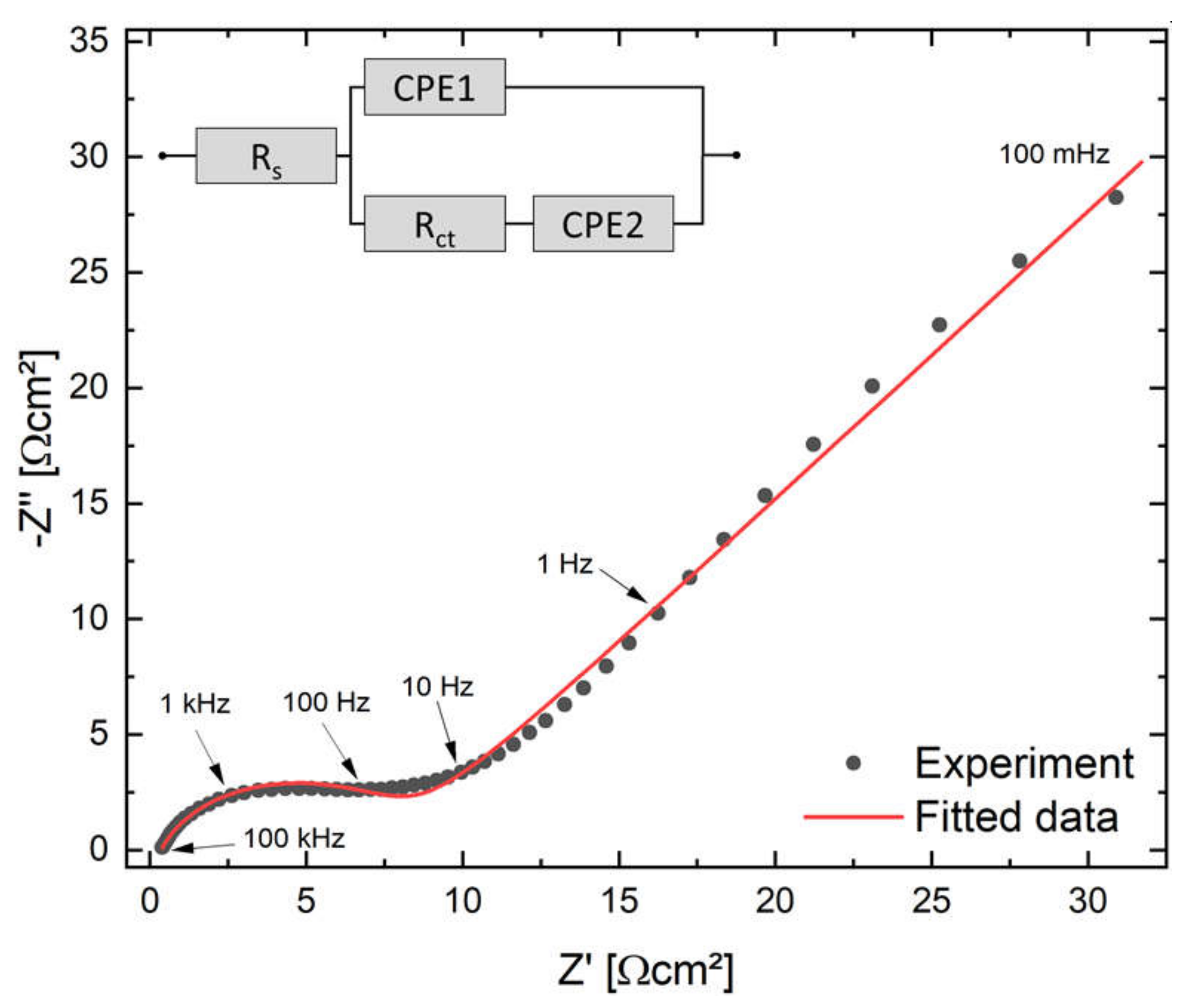
3.2.4. Electrochemical Impedance Spectroscopy (EIS)
4. Conclusions
Author Contributions
Funding
Institutional Review Board Statement
Informed Consent Statement
Data Availability Statement
Acknowledgments
Conflicts of Interest
References
- Chen, X.; Paul, R.; Dai, L. Carbon-based supercapacitors for efficient energy storage. Natl. Sci. Rev. 2017, 4, 453–489. [Google Scholar] [CrossRef]
- Larcher, D.; Tarascon, J.-M. Towards greener and more sustainable batteries for electrical energy storage. Nat. Chem. 2014, 7, 19–29. [Google Scholar] [CrossRef]
- Huang, Y.; Zhu, M.; Pei, Z.; Li, H.; Wang, Z.; Xue, Q.; Zhi, C. Multifunctional Energy Storage and Conversion Devices. Adv. Mater. 2016, 28, 8344–8364. [Google Scholar] [CrossRef] [PubMed]
- Simon, P.; Gogotsi, Y.; Dunn, B. Where Do Batteries End and Supercapacitors Begin? Science 2014, 343, 1210–1211. [Google Scholar] [CrossRef] [PubMed] [Green Version]
- Xiao, H.; Wu, Z.-S.; Chen, L.; Zhou, F.; Zheng, S.; Ren, W.; Cheng, H.-M.; Bao, X. One-Step Device Fabrication of Phosphorene and Graphene Interdigital Micro-Supercapacitors with High Energy Density. ACS Nano 2017, 11, 7284–7292. [Google Scholar] [CrossRef]
- Huang, Y.; Zhong, M.; Shi, F.; Liu, X.; Tang, Z.; Wang, Y.; Hou, H.; Xie, X.; Zhi, C. An Intrinsically Stretchable and Compressible Supercapacitor Containing a Polyacrylamide Hydrogel Electrolyte. Angew. Chem. Int. Ed. 2017, 56, 9141–9145. [Google Scholar] [CrossRef] [PubMed]
- Zhu, J.; Feng, T.; Du, X.; Wang, J.; Hu, J.; Wei, L. High performance asymmetric supercapacitor based on polypyrrole/graphene composite and its derived nitrogen-doped carbon nano-sheets. J. Power Sources 2017, 346, 120–127. [Google Scholar] [CrossRef]
- Shumakovich, G.P.; Morozova, O.V.; Khlupova, M.E.; Vasil’Eva, I.S.; Zaitseva, E.A.; Yaropolov, A.I. Enhanced performance of a flexible supercapacitor due to a combination of the pseudocapacitances of both a PANI/MWCNT composite electrode and a gel polymer redox electrolyte. RSC Adv. 2017, 7, 34192–34196. [Google Scholar] [CrossRef] [Green Version]
- Xu, M.; Song, Y.; Ye, Y.; Gong, C.; Shen, Y.; Wang, L.; Wang, L. A novel flexible electrochemical glucose sensor based on gold nanoparticles/polyaniline arrays/carbon cloth electrode. Sens. Actuators B Chem. 2017, 252, 1187–1193. [Google Scholar] [CrossRef]
- Peng, H.; Ma, G.; Sun, K.; Mu, J.; Zhou, X.; Lei, Z. A novel fabrication of nitrogen-containing carbon nanospheres with high rate capability as electrode materials for supercapacitors. RSC Adv. 2015, 5, 12034–12042. [Google Scholar] [CrossRef]
- Jagadale, A.; Dubal, D.; Lokhande, C. Electrochemical behavior of potentiodynamically deposited cobalt oxyhydroxide (CoOOH) thin films for supercapacitor application. Mater. Res. Bull. 2012, 47, 672–676. [Google Scholar] [CrossRef]
- Chee, W.K.; Lim, H.N.; Zainal, Z.; Huang, N.M.; Harrison, I.; Andou, Y. Flexible Graphene-Based Supercapacitors: A Review. J. Phys. Chem. C 2016, 120, 4153–4172. [Google Scholar] [CrossRef]
- Ramya, R.; Sivasubramanian, R.; Sangaranarayanan, M. Conducting polymers-based electrochemical supercapacitors—Progress and prospects. Electrochim. Acta 2013, 101, 109–129. [Google Scholar] [CrossRef]
- Razali, S.A.; Majid, S.R. Fabrication of polyaniline nanorods on electro-etched carbon cloth and its electrochemical activities as electrode materials. Ionics 2018, 25, 2575–2584. [Google Scholar] [CrossRef]
- Huang, Y.; Li, H.; Wang, Z.; Zhu, M.; Pei, Z.; Xue, Q.; Zhi, C. Nanostructured Polypyrrole as a flexible electrode material of supercapacitor. Nano Energy 2016, 22, 422–438. [Google Scholar] [CrossRef]
- Eftekhari, A.; Li, L.; Yang, Y. Polyaniline supercapacitors. J. Power Sources 2017, 347, 86–107. [Google Scholar] [CrossRef]
- Bilal, S.; Gul, S.; Holze, R.; Shah, A.-U.A. An impressive emulsion polymerization route for the synthesis of highly soluble and conducting polyaniline salts. Synth. Met. 2015, 206, 131–144. [Google Scholar] [CrossRef]
- Sha, R.; Badhulika, S. Binder free platinum nanoparticles decorated graphene-polyaniline composite film for high performance supercapacitor application. Electrochim. Acta 2017, 251, 505–512. [Google Scholar] [CrossRef]
- Malik, R.; Zhang, L.; McConnell, C.; Schott, M.; Hsieh, Y.-Y.; Noga, R.; Alvarez, N.T.; Shanov, V. Three-dimensional, free-standing polyaniline/carbon nanotube composite-based electrode for high-performance supercapacitors. Carbon 2017, 116, 579–590. [Google Scholar] [CrossRef]
- Deshmukh, P.; Shinde, N.; Patil, S.; Bulakhe, R.; Lokhande, C. Supercapacitive behavior of polyaniline thin films deposited on fluorine doped tin oxide (FTO) substrates by microwave-assisted chemical route. Chem. Eng. J. 2013, 223, 572–577. [Google Scholar] [CrossRef]
- Gawli, Y.; Banerjee, A.; Dhakras, D.; Deo, M.; Bulani, D.; Wadgaonkar, P.; Shelke, M.; Ogale, S. 3D Polyaniline Architecture by Concurrent Inorganic and Organic Acid Doping for Superior and Robust High Rate Supercapacitor Performance. Sci. Rep. 2016, 6, 21002. [Google Scholar] [CrossRef] [PubMed] [Green Version]
- Fahim, M.; Shah, A.U.H.A.; Bilal, S. Highly Stable and Efficient Performance of Binder-Free Symmetric Supercapacitor Fabricated with Electroactive Polymer Synthesized via Interfacial Polymerization. Materials 2019, 12, 1626. [Google Scholar] [CrossRef] [PubMed] [Green Version]
- Gul, H.; Shah, A.-U.A.; Krewer, U.; Bilal, S. Study on Direct Synthesis of Energy Efficient Multifunctional Polyaniline–Graphene Oxide Nanocomposite and Its Application in Aqueous Symmetric Supercapacitor Devices. Nanomaterials 2020, 10, 118. [Google Scholar] [CrossRef] [PubMed] [Green Version]
- Dinh, H.N.; Viola, I.B. Effect of Substrate on Polyaniline Film Properties A Cyclic Voltammetry and Impedance Study. J. Electrochem. Soc. 2000, 147, 3775–3784. [Google Scholar] [CrossRef]
- Rolison, D.R.; Long, J.W.; Lytle, J.C.; Fischer, A.E.; Rhodes, C.P.; McEvoy, T.M.; Bourg, M.E.; Lubers, A.M.; Rolison, D.R.; Long, J.W.; et al. Multifunctional 3D nanoarchitectures for energy storage and conversion. Chem. Soc. Rev. 2009, 38, 226–252. [Google Scholar] [CrossRef]
- Rahman, S.U.; Röse, P.; Shah, A.U.H.A.; Krewer, U.; Bilal, S. An Amazingly Simple, Fast and Green Synthesis Route to Polyaniline Nanofibers for Efficient Energy Storage. Polymers 2020, 12, 2212. [Google Scholar] [CrossRef]
- Shayeh, J.S.; Norouzi, P.; Ganjali, M.R. Studying the supercapacitive behavior of a polyaniline/nano-structural manganese dioxide composite using fast Fourier transform continuous cyclic voltammetry. RSC Adv. 2015, 5, 20446–20452. [Google Scholar] [CrossRef]
- Xiang, C.; Li, M.; Zhi, M.; Manivannan, A.; Wu, N.; Xiang, C.; Li, M.; Zhi, M.; Manivannan, A.; Wu, N. A reduced graphene oxide/Co3O4 composite for supercapacitor electrode. J. Power Sources 2013, 226, 65–70. [Google Scholar] [CrossRef] [Green Version]
- Tian, Z.R.; Liu, J.; Voigt, J.A.; Xu, A.H.; Mcdermott†, M.J. Dendritic Growth of Cubically Ordered Nanoporous Materials through Self-Assembly. Nano Lett. 2002, 3, 89–92. [Google Scholar] [CrossRef]
- Tran, H.D.; D’Arcy, J.M.; Wang, Y.; Beltramo, P.; Strong, V.A.; Kaner, R.B. The oxidation of aniline to produce “polyaniline”: A process yielding many different nanoscale structures. J. Mater. Chem. 2011, 21, 3534–3550. [Google Scholar] [CrossRef]
- Zhao, Y.; Liu, B.; Pan, L.; Yu, G. 3D nanostructured conductive polymer hydrogels for high-performance electrochemical devices. Energy Environ. Sci. 2013, 6, 2856–2870. [Google Scholar] [CrossRef]
- Pan, L.; Yu, G.; Zhai, D.; Lee, H.R.; Zhao, W.; Liu, N.; Wang, H.; Tee, C.K.; Shi, Y.; Cui, Y.; et al. Hierarchical nanostructured conducting polymer hydrogel with high electrochemical activity. Proc. Natl. Acad. Sci. USA 2012, 109, 9287–9292. [Google Scholar] [CrossRef] [PubMed] [Green Version]
- Gao, X.; Jing, X.; Li, Y.; Zhu, J.; Zhang, M. Synthesis and characterization of phosphorized polyaniline doped with phytic acid and its anticorrosion properties for Mg-Li alloy. J. Macromol. Sci. Part A 2017, 55, 24–35. [Google Scholar] [CrossRef]
- Palaniappan, S.; Srinivas, P. Nano fibre polyaniline containing long chain and small molecule dopants and carbon composites for supercapacitor. Electrochim. Acta 2013, 95, 251–259. [Google Scholar] [CrossRef]
- Yu, T.; Zhu, P.; Xiong, Y.; Chen, H.; Kang, S.; Luo, H.; Guan, S. Synthesis of microspherical polyaniline/graphene composites and their application in supercapacitors. Electrochim. Acta 2016, 222, 12–19. [Google Scholar] [CrossRef]
- Singh, R.K.; Kumar, A.; Agarwal, K.; Dwivedi, D.; Sood, K.N.; Singh, R. Influence of Binary Oxidant (FeCl3:APS) Ratio on the Spectroscopic and Microscopic Properties of Poly(2,5-Dimethoxyaniline). Open J. Polym. Chem. 2012, 2, 105–112. [Google Scholar] [CrossRef] [Green Version]
- Sasikumar, Y.; Kumar, A.M.; Gasem, Z.M.; Ebenso, E. Hybrid nanocomposite from aniline and CeO2 nanoparticles: Surface protective performance on mild steel in acidic environment. Appl. Surf. Sci. 2015, 330, 207–215. [Google Scholar] [CrossRef]
- Santos, L.; Branco, J.; Guimarães, I.; Motheo, A. Synthesis in phytic acid medium and application as anticorrosive coatings of polyaniline-based materials. Surf. Coatings Technol. 2015, 275, 26–31. [Google Scholar] [CrossRef]
- Song, E.; Choi, J.-W. Conducting Polyaniline Nanowire and Its Applications in Chemiresistive Sensing. Nanomaterials 2013, 3, 498–523. [Google Scholar] [CrossRef] [PubMed]
- Basnayaka, P.A.; Ram, M.K.; Stefanakos, E.K.; Kumar, A. Supercapacitors based on graphene–polyaniline derivative nanocomposite electrode materials. Electrochim. Acta 2013, 92, 376–382. [Google Scholar] [CrossRef]
- Wu, J.; Zhang, Q.; Wang, J.-J.; Huang, X.; Bai, H. A self-assembly route to porous polyaniline/reduced graphene oxide composite materials with molecular-level uniformity for high-performance supercapacitors. Energy Environ. Sci. 2018, 11, 1280–1286. [Google Scholar] [CrossRef]
- Genies, E.; Tsintavis, C. Redox mechanism and electrochemical behaviour or polyaniline deposits. J. Electroanal. Chem. Interfacial Electrochem. 1985, 195, 109–128. [Google Scholar] [CrossRef]
- Liu, B.; Zhang, X.; Tian, D.; Li, Q.; Zhong, M.; Chen, S.; Hu, C.; Ji, H. In Situ Growth of Oriented Polyaniline Nanorod Arrays on the Graphite Flake for High-Performance Supercapacitors. ACS Omega 2020, 8, 32395–32402. [Google Scholar] [CrossRef]
- Sayah, A.; Habelhames, F.; Bahloul, A.; Nessark, B.; Bonnassieux, Y.; Tendelier, D.; El Jouad, M. Electrochemical synthesis of polyaniline-exfoliated graphene composite films and their capacitance properties. J. Electroanal. Chem. 2018, 818, 26–34. [Google Scholar] [CrossRef]
- Lakshmi, M.S.; Wabaidur, S.M.; Alothman, Z.A.; Ragupathy, D. Novel 1D polyaniline nanorods for efficient electrochemical supercapacitors: A facile and green approach. Synth. Met. 2020, 270, 116591. [Google Scholar] [CrossRef]
- Gul, H.; Shah, A.-U.A.; Bilal, S. Achieving Ultrahigh Cycling Stability and Extended Potential Window for Supercapacitors through Asymmetric Combination of Conductive Polymer Nanocomposite and Activated Carbon. Polymers 2019, 11, 1678. [Google Scholar] [CrossRef] [Green Version]
- Sayah, A.; Habelhames, F.; Bennouioua, A.; Bahloul, A.; Ghalmi, Y. Capacitance of polyaniline films synthesized by direct and pulse potentiostatic methods. J. Mar. Chim. Heterocycl. 2021, 20, 108–116. [Google Scholar]
- Gul, H.; Shah, A.-U.A.; Bilal, S. Fabrication of Eco-Friendly Solid-State Symmetric Ultracapacitor Device Based on Co-Doped PANI/GO Composite. Polymers 2019, 11, 1315. [Google Scholar] [CrossRef] [PubMed] [Green Version]
- Rahman, S.U.; Röse, P.; Surati, M.; Shah, A.U.H.A.; Krewer, U.; Bilal, S. 3D Polyaniline Nanofibers Anchored on Carbon Paper for High-Performance and Light-Weight Supercapacitors. Polymers 2020, 12, 2705. [Google Scholar] [CrossRef] [PubMed]
- Wang, Y.; Shi, Z.; Huang, Y.; Ma, Y.; Wang, C.; Chen, M.; Chen, Y. Supercapacitor Devices Based on Graphene Materials. J. Phys. Chem. C 2009, 113, 13103–13107. [Google Scholar] [CrossRef]


| Scan Rate/ mVs−1 | Specific Capacitance (Fg−1) of FTO-PANI Electrode without Binder | Specific Capacitance a (Fg−1) of FTO-PANI Electrode with Binder |
|---|---|---|
| 20 | 666.6 ± 2.1 | 340.0 ± 2.1 |
| 50 | 617.6 ± 2.2 | 331.6 ± 2.3 |
| 100 | 548.7 ± 2.1 | 302.3 ± 2.6 |
| 150 | 481.7 ± 2.3 | 279.0 ± 2.4 |
| 200 | 428.6 ± 2.3 | 261.2 ± 2.5 |
| 250 | 384.0 ± 2.5 | 246.4 ± 2.3 |
| 300 | 346.0 ± 2.5 | 228.3 ± 2.4 |
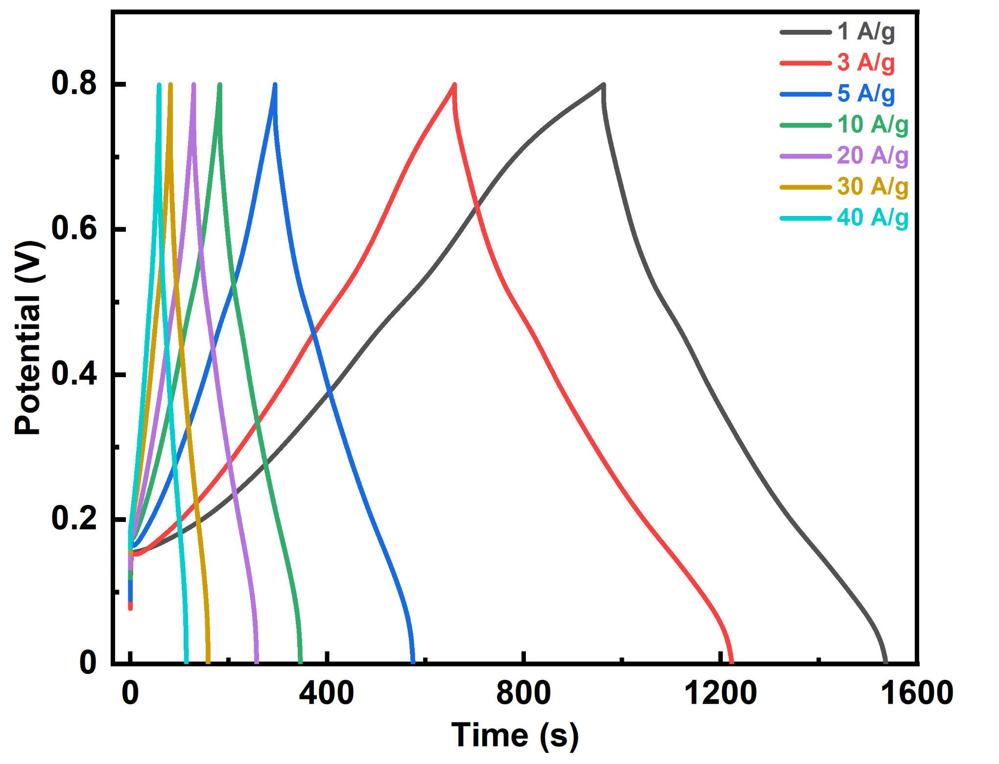
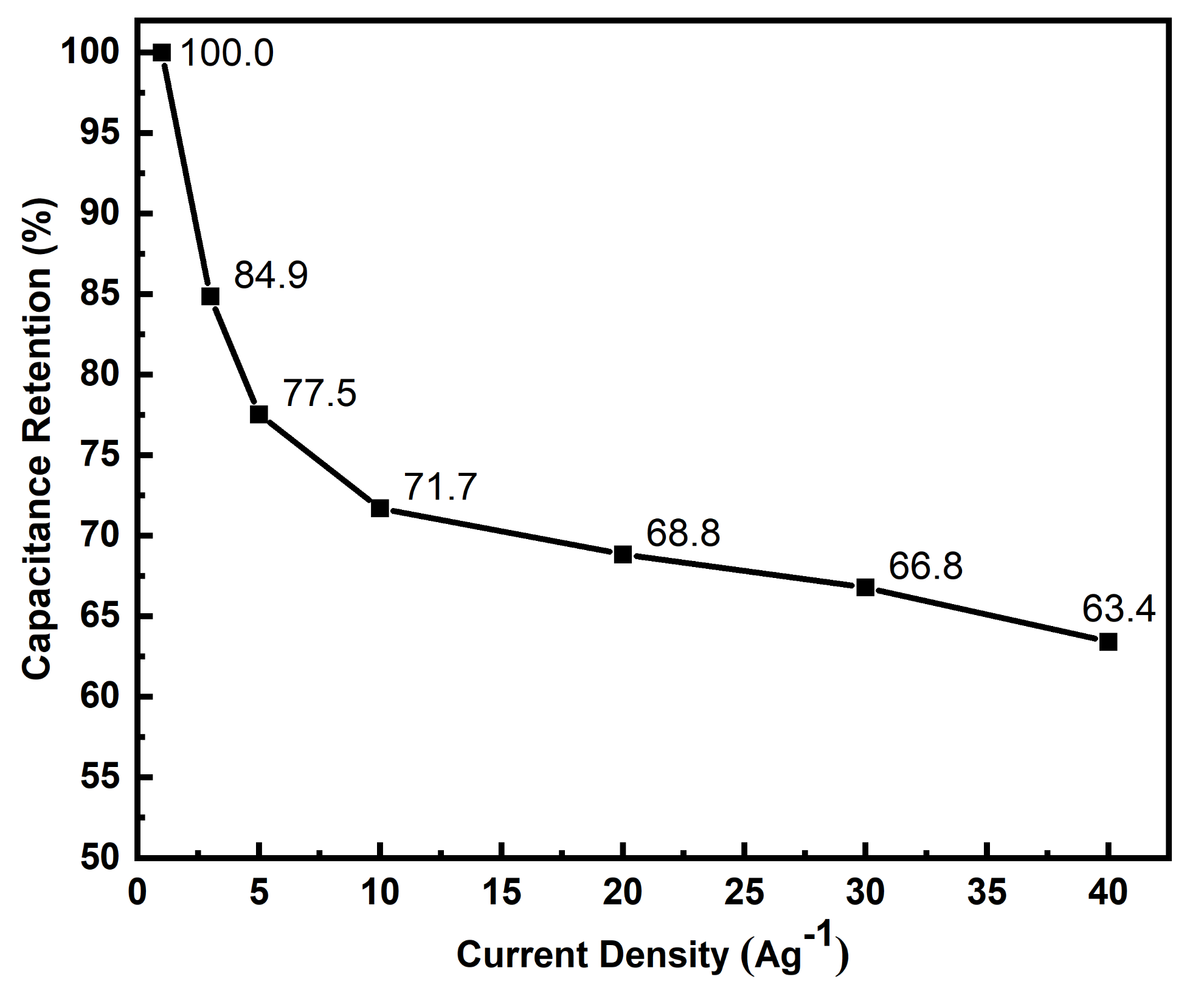
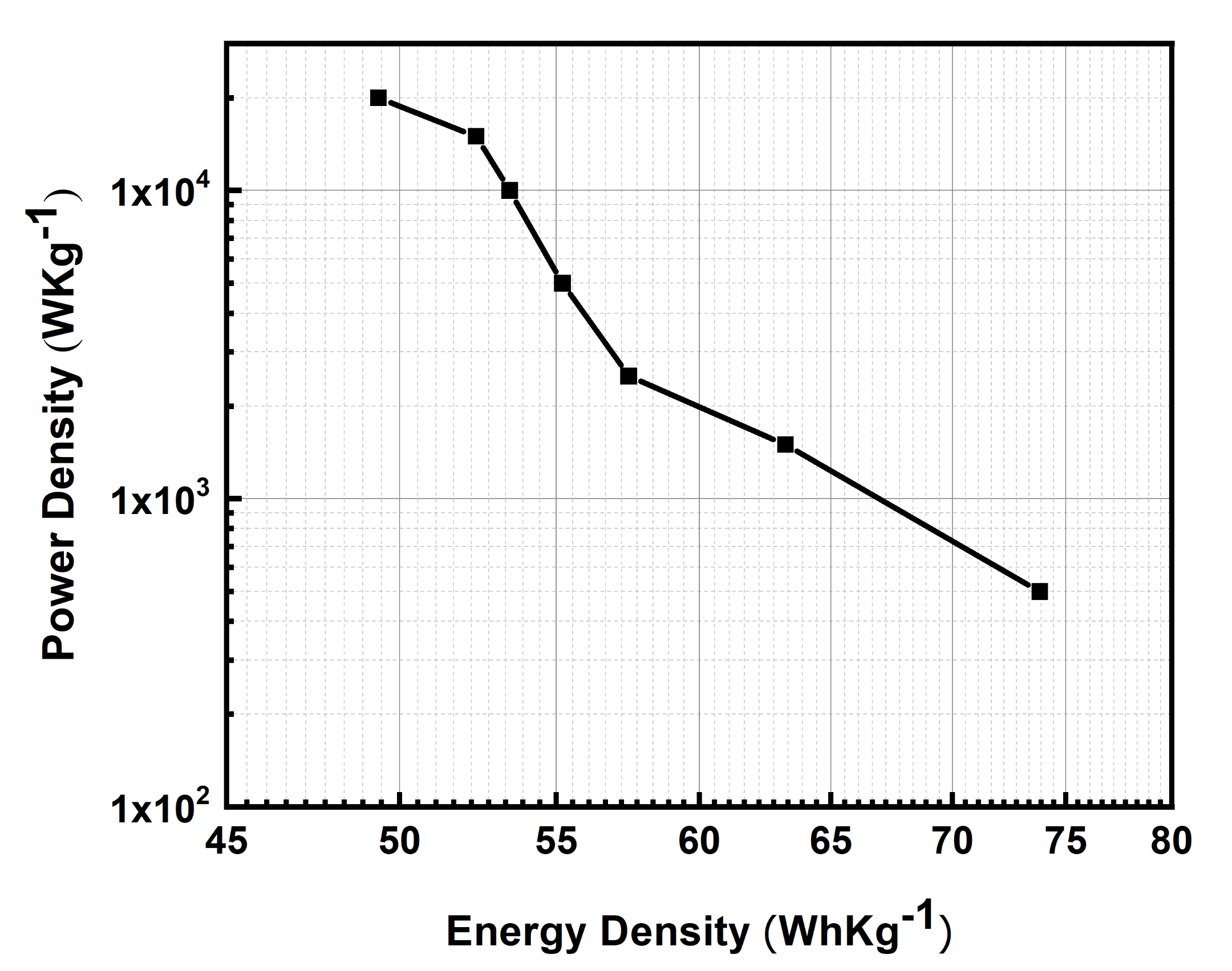
| Current Density/ Ag−1 | Specific Capacitance a /Fg−1 | Capacitance Retention b | Energy Density/Whkg−1 | Power Density/ Wkg−1 |
|---|---|---|---|---|
| 1 | 531.5 ± 2.2 | - | 73.8 | 500 |
| 3 | 455.3 ± 2.1 | 86% | 63.2 | 1500 |
| 5 | 413.8 ± 2.0 | 78% | 57.5 | 2500 |
| 10 | 397.5 ± 2.3 | 75% | 55.2 | 5000 |
| 20 | 385.0 ± 2.1 | 72% | 53.5 | 10,000 |
| 30 | 377.2 ± 2.0 | 71% | 52.4 | 15,000 |
| 40 | 355.4 ± 2.2 | 69% | 49.4 | 20,000 |
| Materials a | Current Density | Specific Capacitance | Year | Reference |
|---|---|---|---|---|
| PANI-DBSA-Gold | 10 Ag−1 | 215 Fg−1 | 2019 | [22] |
| PANI-GO-Gold | 1 Ag−1 | 264 Fg−1 | 2020 | [23] |
| FTO/PANI | 0.1 Ag−1 | 176.29 Fg−1 | 2018 | [44] |
| PANI-NR coated-FTO | 1 Ag−1 | 106 Fg−1 | 2020 | [45] |
| PANI-FTO//PANI-TiO-FTO | 5 Ag−1 | 419 Fg−1 | 2019 | [46] |
| FTO/PANI | 0.2 Ag−1 | 155.65 Fg−1 | 2021 | [47] |
| PANI-ACP | 1 Ag−1 | 402 Fg−1 | 2020 | [48] |
| PANI-FTO | 1 Ag−1 | 531.5 ± 2.2 Fg−1 | present work | |
| 40 Ag−1 | 355.4 ± 2.2 Fg−1 | |||
Publisher’s Note: MDPI stays neutral with regard to jurisdictional claims in published maps and institutional affiliations. |
© 2021 by the authors. Licensee MDPI, Basel, Switzerland. This article is an open access article distributed under the terms and conditions of the Creative Commons Attribution (CC BY) license (https://creativecommons.org/licenses/by/4.0/).
Share and Cite
Ur Rahman, S.; Röse, P.; ul Haq Ali Shah, A.; Krewer, U.; Bilal, S.; Farooq, S. Exploring the Functional Properties of Sodium Phytate Doped Polyaniline Nanofibers Modified FTO Electrodes for High-Performance Binder Free Symmetric Supercapacitors. Polymers 2021, 13, 2329. https://doi.org/10.3390/polym13142329
Ur Rahman S, Röse P, ul Haq Ali Shah A, Krewer U, Bilal S, Farooq S. Exploring the Functional Properties of Sodium Phytate Doped Polyaniline Nanofibers Modified FTO Electrodes for High-Performance Binder Free Symmetric Supercapacitors. Polymers. 2021; 13(14):2329. https://doi.org/10.3390/polym13142329
Chicago/Turabian StyleUr Rahman, Sami, Philipp Röse, Anwar ul Haq Ali Shah, Ulrike Krewer, Salma Bilal, and Shehna Farooq. 2021. "Exploring the Functional Properties of Sodium Phytate Doped Polyaniline Nanofibers Modified FTO Electrodes for High-Performance Binder Free Symmetric Supercapacitors" Polymers 13, no. 14: 2329. https://doi.org/10.3390/polym13142329
APA StyleUr Rahman, S., Röse, P., ul Haq Ali Shah, A., Krewer, U., Bilal, S., & Farooq, S. (2021). Exploring the Functional Properties of Sodium Phytate Doped Polyaniline Nanofibers Modified FTO Electrodes for High-Performance Binder Free Symmetric Supercapacitors. Polymers, 13(14), 2329. https://doi.org/10.3390/polym13142329