Integration of Polypyrrole Electrode into Piezoelectric PVDF Energy Harvester with Improved Adhesion and Over-Oxidation Resistance


Abstract
1. Introduction
2. Materials and Methods
2.1. Materials
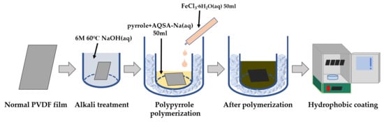
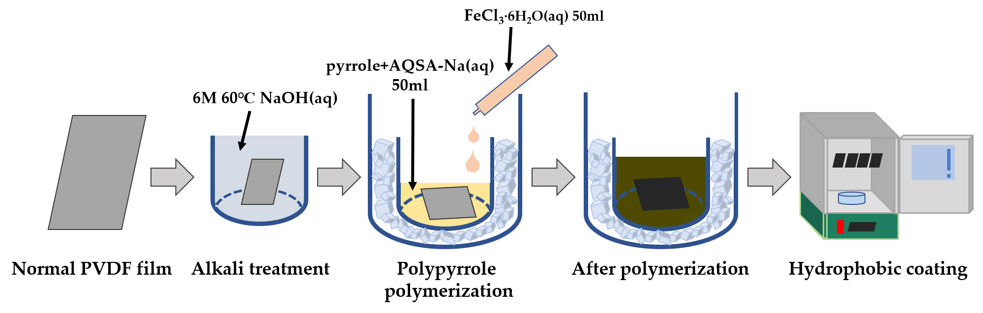
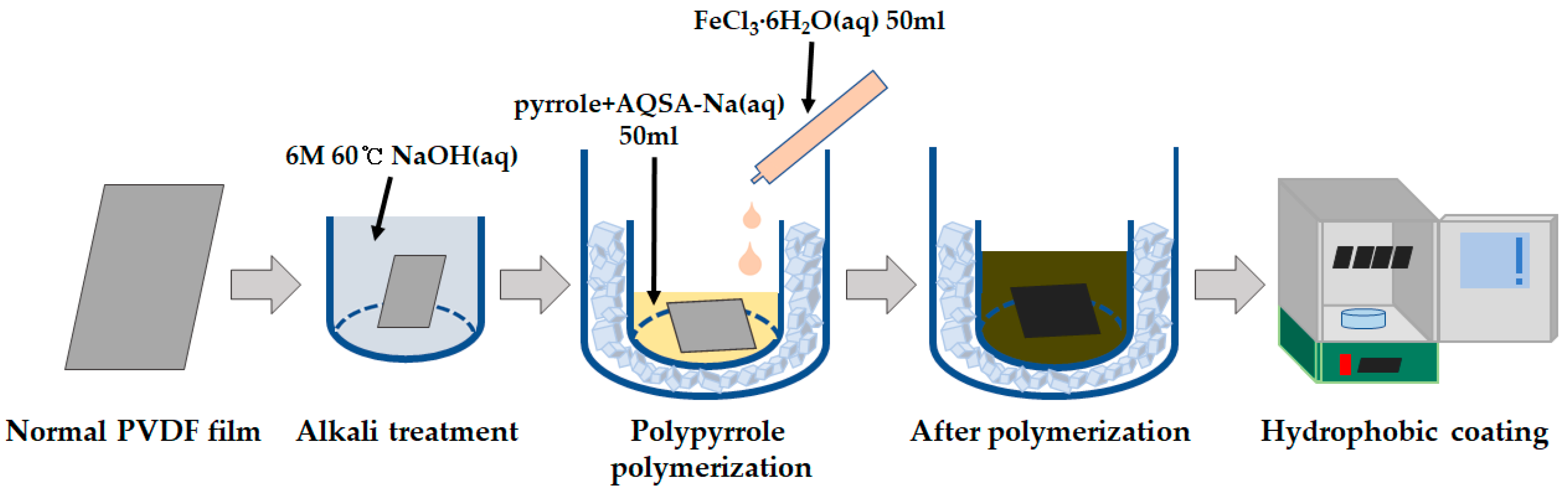
2.2. Fabrications
2.2.1. Alkaline Treatment
2.2.2. Polypyrrole Polymerization for Electrode Formation
2.2.3. Hydrophobic Coating by Chemical Vapor Deposition
2.3. Characterization
2.3.1. Morphology
2.3.2. Surface Resistivity
- : Surface resistivity of sample;
- : Resistance measured with a DC milliohm meter;
- : Width of copper strip (30 mm);
- : Distance between copper strips (20 mm).
2.3.3. Water Contact Angle
2.3.4. Fourier-Transform Infrared (FT-IR) Spectroscopy
2.3.5. Piezoelectricity
2.3.6. Adhesion Durability
2.3.7. Resistance to Over-Oxidation by Water
- : Change in sample surface resistivity;
- : Surface resistivity of non-immersed sample;
- : Surface resistivity of sample after immersion.
3. Results and Discussion
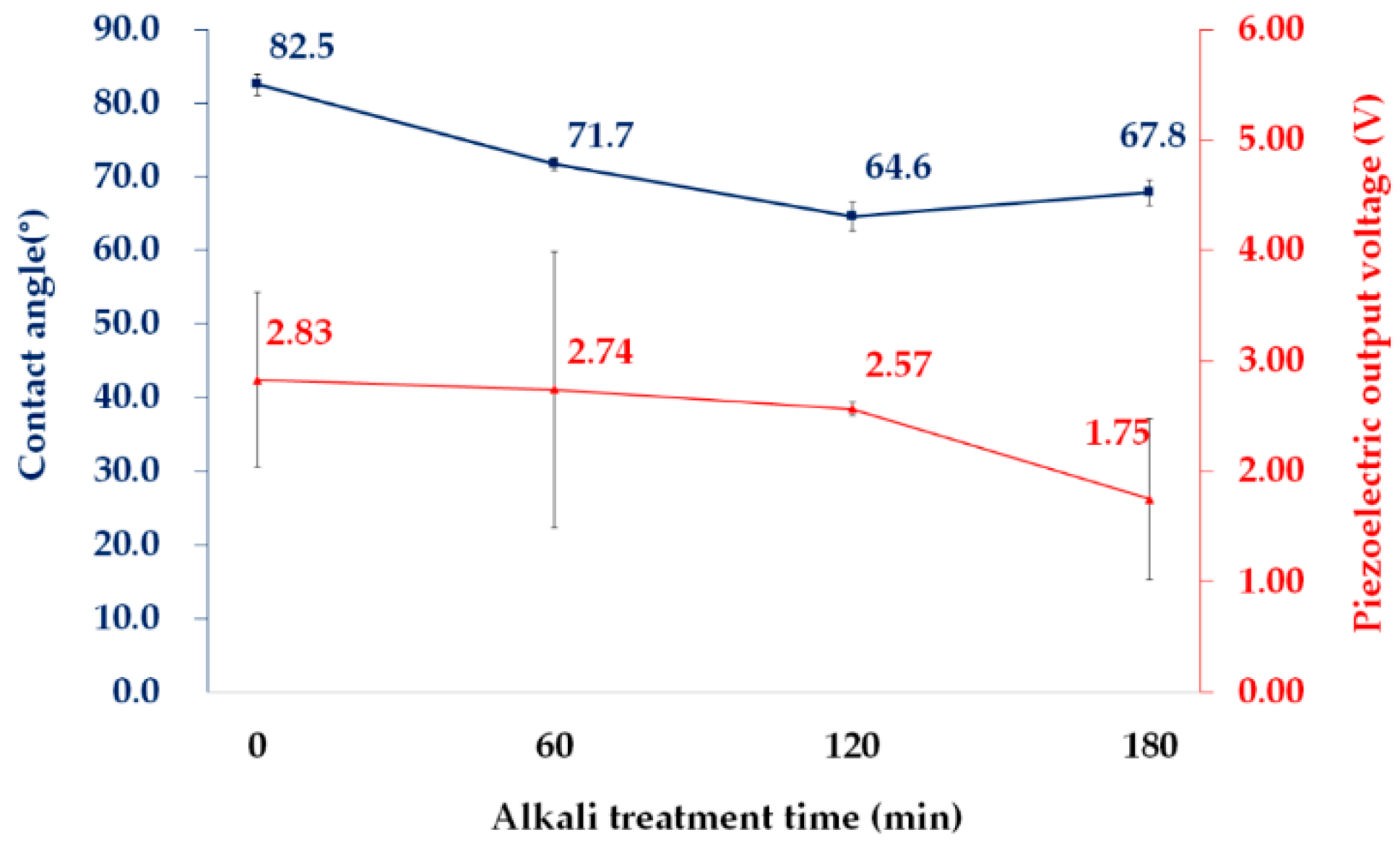
3.1. Enhancement of Adhesive Property of PVDF Film by Alkaline Treatment
3.2. Effects of Alkaline Treatment, PPy Polymerization, and Hydrophobic Coating on Properties of PVDF Films
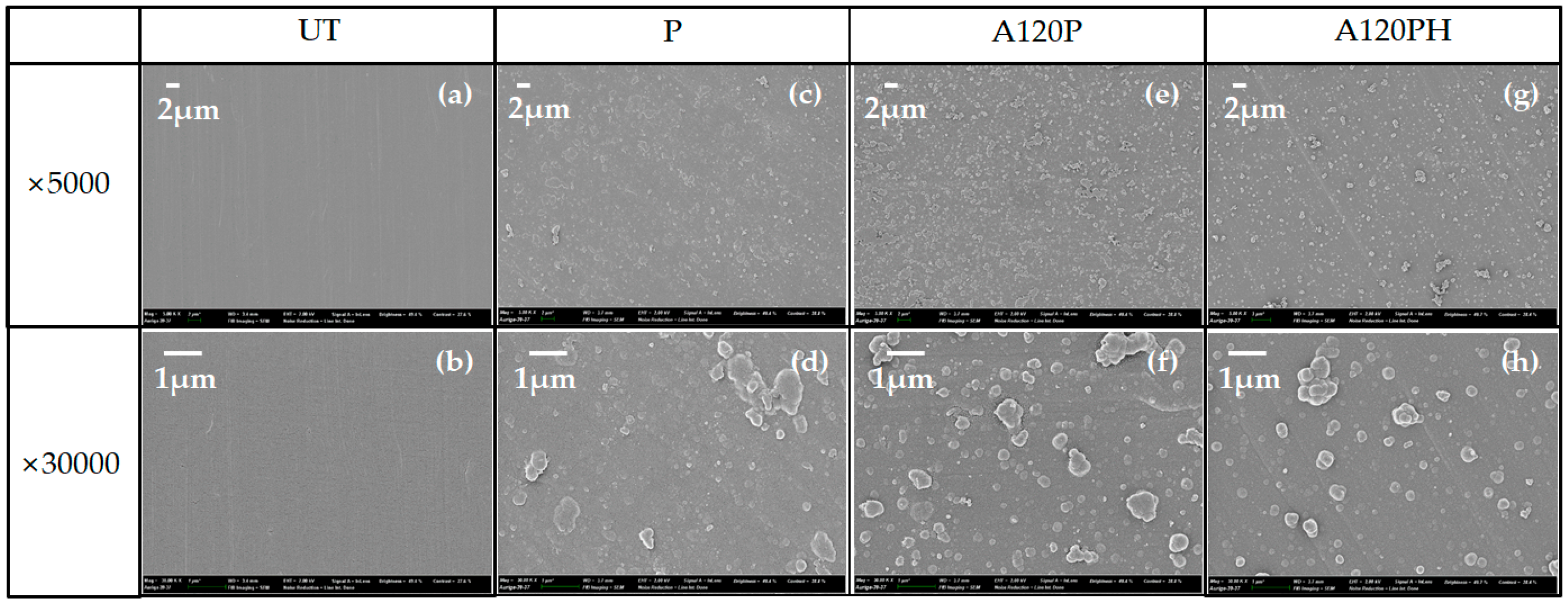
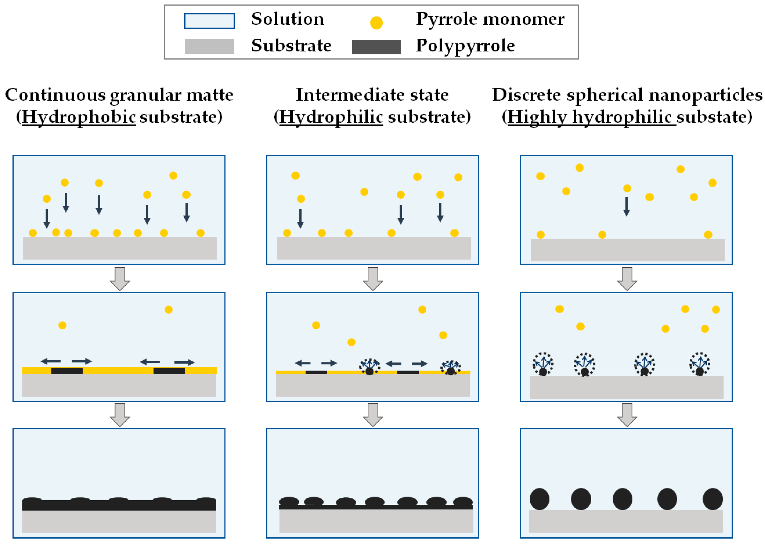
3.2.1. Morphology
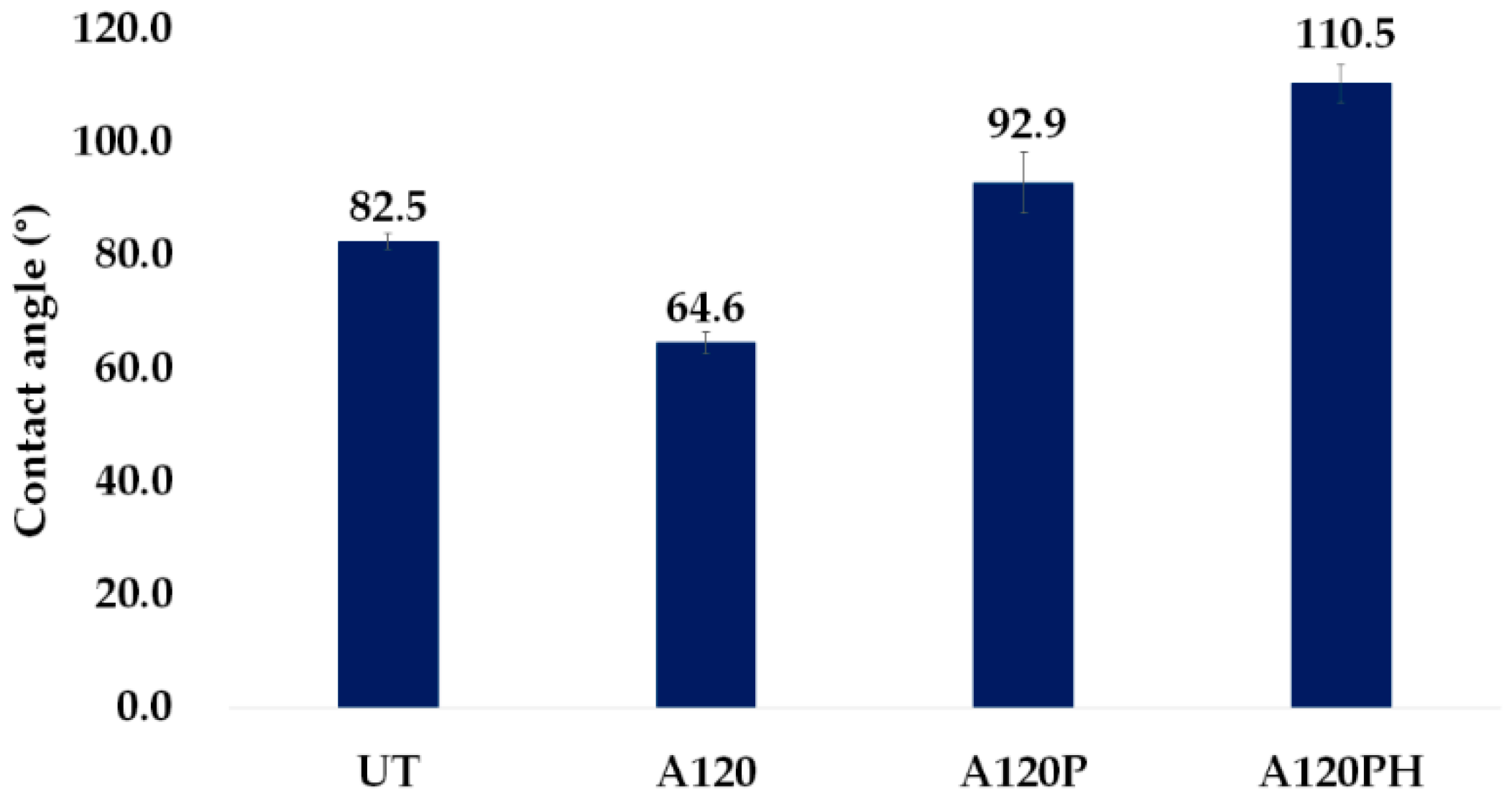
3.2.2. Wettability
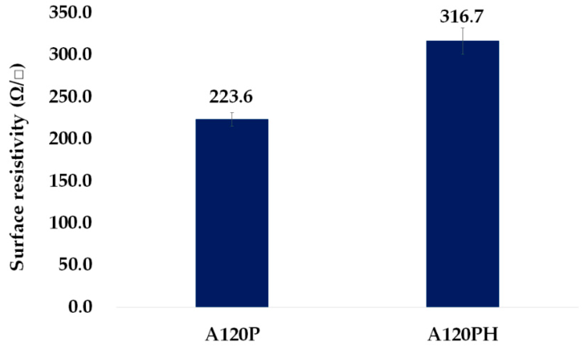
3.2.3. Electric and Piezoelectric Properties
3.3. Durability
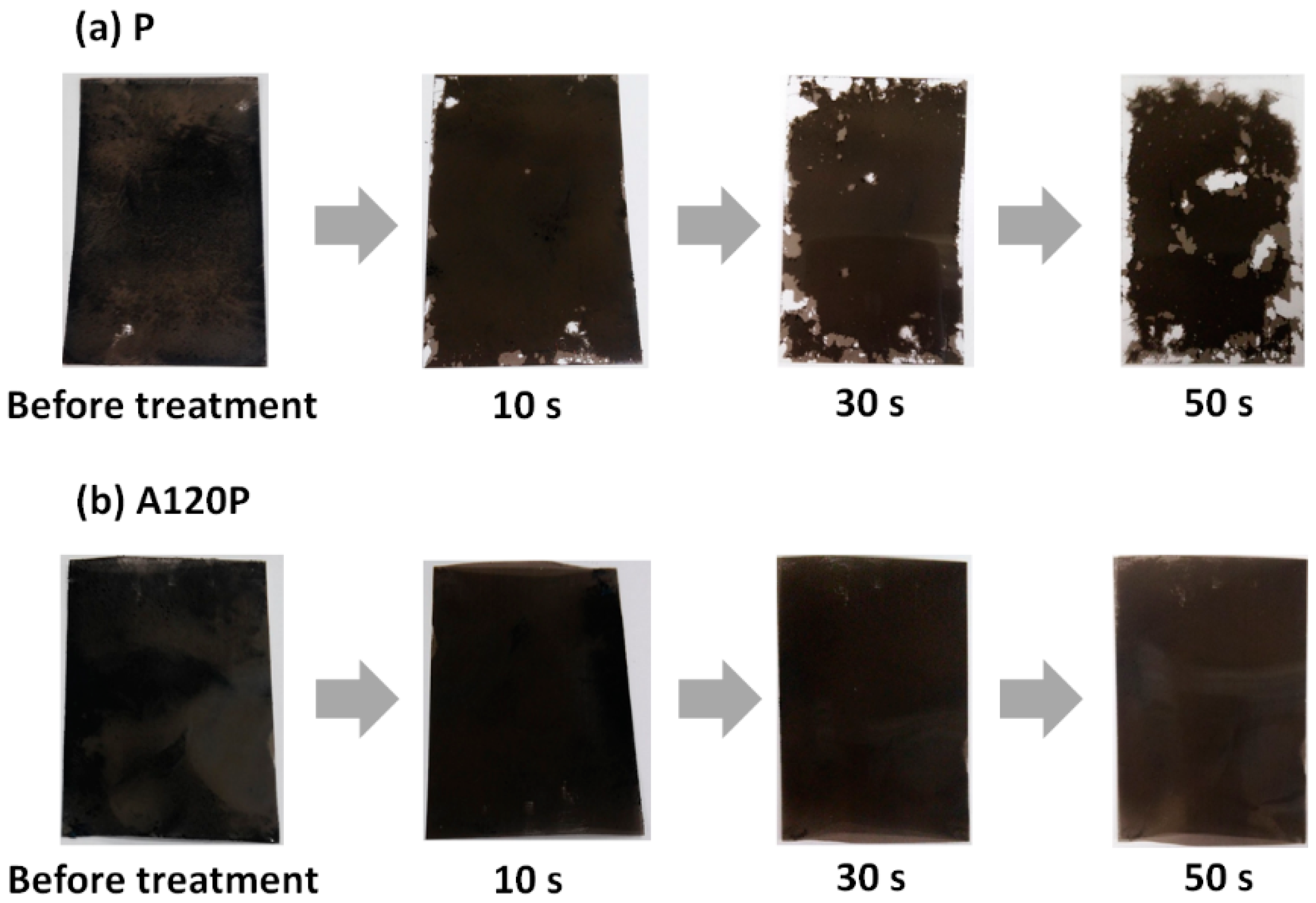
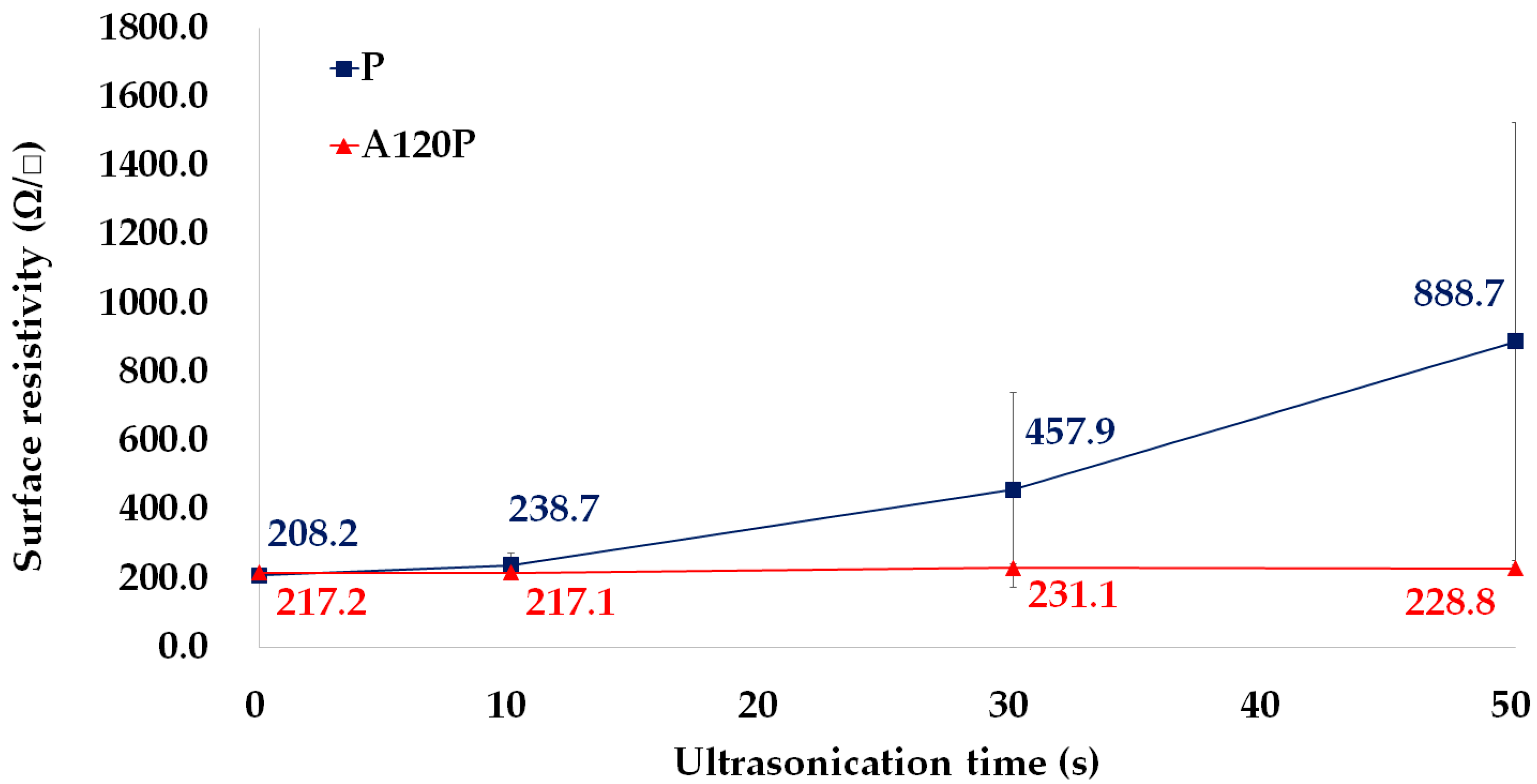
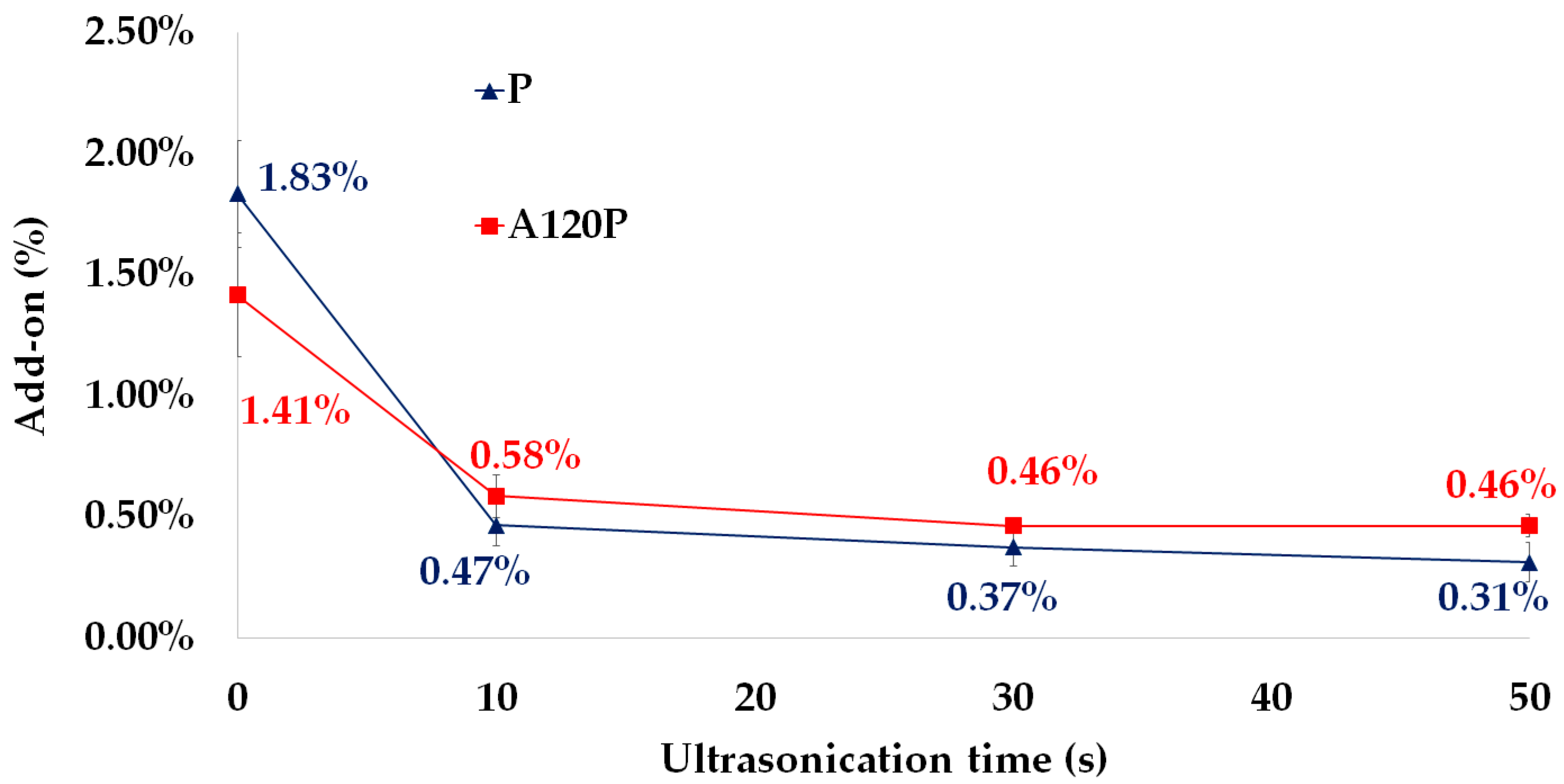
3.3.1. Adhesion between PVDF Films and PPy Electrodes
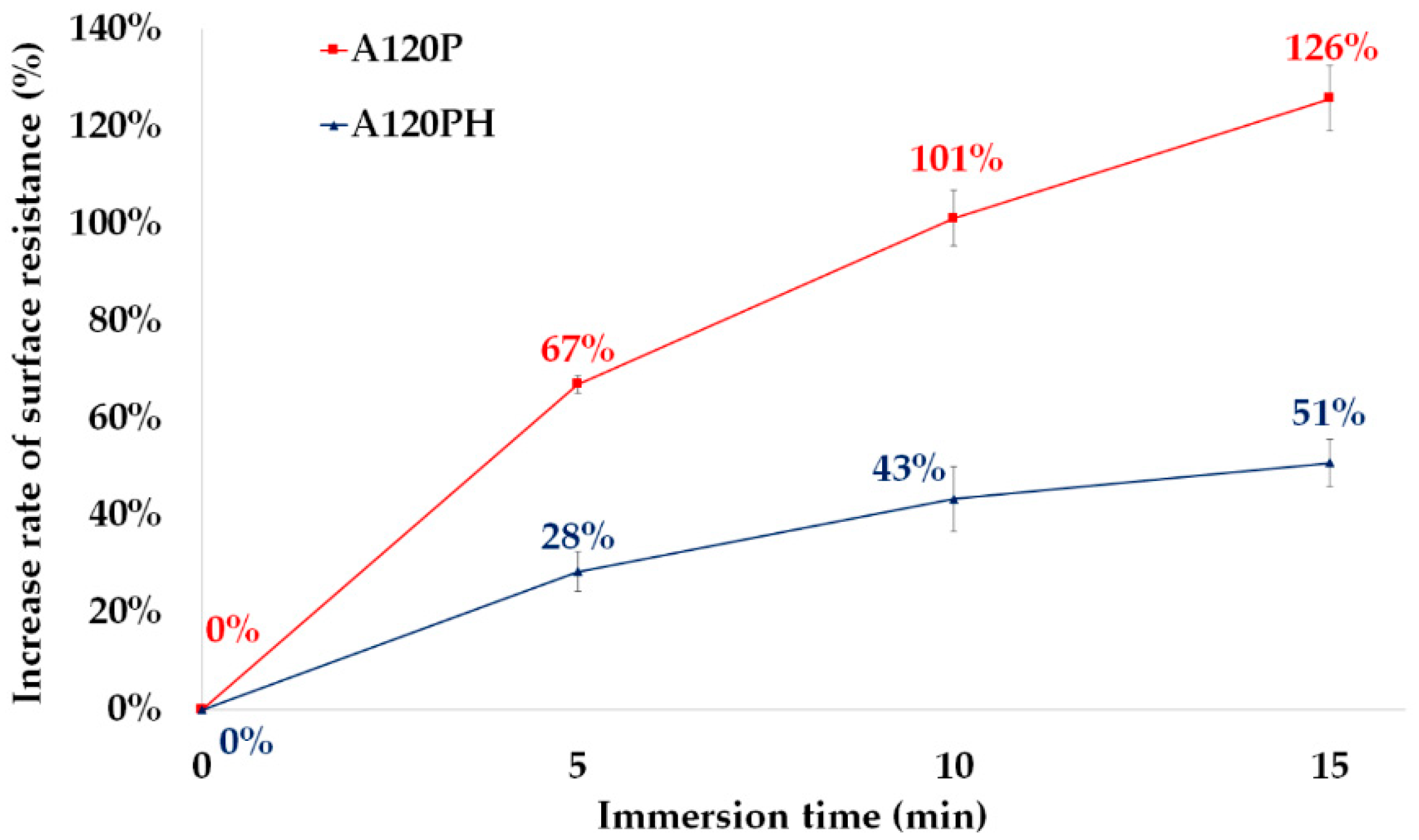
3.3.2. Resistance to Over-Oxidation by Water
4. Conclusions
Author Contributions
Funding
Conflicts of Interest
Appendix A


References
- Crawford, K.; Lingel, J.; Karppi, T. Our metrics, ourselves: A hundred years of self-tracking from the weight scale to the wrist wearable device. Eur. J. Cult. Stud. 2015, 18, 479–496. [Google Scholar] [CrossRef]
- Do, Q.; Martini, B.; Choo, K.K.R. Is the data on your wearable device secure? An Android Wear smartwatch case study. Softw. Pract. Exp. 2017, 47, 391–403. [Google Scholar] [CrossRef]
- Kroll, R.R.; Boyd, J.G.; Maslove, D.M. Accuracy of a wrist-worn wearable device for monitoring heart rates in hospital inpatients: A prospective observational study. J. Med. Internet Res. 2016, 18, e253. [Google Scholar] [CrossRef] [PubMed]
- Koo, S.H.; Fallon, K. Explorations of wearable technology for tracking self and others. Fash. Text. 2018, 5, 8. [Google Scholar] [CrossRef]
- Lee, Y.A.; Koo, S.H. Introduction to special collection on 3D printing and wearable technology in fashion. Fash. Text. 2018, 5, 34. [Google Scholar] [CrossRef]
- Matsuhisa, N.; Kaltenbrunner, M.; Yokota, T.; Jinno, H.; Kuribara, K.; Sekitani, T.; Someya, T. Printable elastic conductors with a high conductivity for electronic textile applications. Nat. Commun. 2015, 6, 7461. [Google Scholar] [CrossRef] [PubMed]
- Shyr, T.W.; Shie, J.W.; Jiang, C.H.; Li, J.J. A textile-based wearable sensing device designed for monitoring the flexion angle of elbow and knee movements. Sensors 2014, 14, 4050–4059. [Google Scholar] [CrossRef]
- Cherenack, K.; Zysset, C.; Kinkeldei, T.; Münzenrieder, N.; Tröster, G. Woven electronic fibers with sensing and display functions for smart textiles. Adv. Mater. (Weinh. Ger.) 2010, 22, 5178–5182. [Google Scholar] [CrossRef]
- Seung, W.; Gupta, M.K.; Lee, K.Y.; Shin, K.S.; Lee, J.H.; Kim, T.Y.; Kim, S.; Lin, J.; Kim, J.H.; Kim, S.W. Nanopatterned textile-based wearable triboelectric nanogenerator. ACS Nano 2015, 9, 3501–3509. [Google Scholar] [CrossRef]
- Bhattacharya, R.; de Kok, M.M.; Zhou, J. Rechargeable electronic textile battery. Appl. Phys. Lett. 2009, 95, 223305. [Google Scholar] [CrossRef]
- Soin, N.; Shah, T.H.; Anand, S.C.; Geng, J.; Pornwannachai, W.; Mandal, P.; Reid, D.; Sharma, S.; Hadimani, R.L.; Bayramol, D.V.; et al. Novel “3-D spacer” all fibre piezoelectric textiles for energy harvesting applications. Energy Environ. Sci. 2014, 7, 1670–1679. [Google Scholar] [CrossRef]
- Ramadan, K.S.; Sameoto, D.; Evoy, S. A review of piezoelectric polymers as functional materials for electromechanical transducers. Smart Mater. Struct. 2014, 23, 033001. [Google Scholar] [CrossRef]
- Park, T.; Kim, B.; Kim, Y.; Kim, E. Highly conductive PEDOT electrodes for harvesting dynamic energy through piezoelectric conversion. J. Mater. Chem. A Mater. 2014, 2, 5462–5469. [Google Scholar] [CrossRef]
- Fuh, Y.K.; Chen, P.C.; Huang, Z.M.; Ho, H.C. Self-powered sensing elements based on direct-write, highly flexible piezoelectric polymeric nano/microfibers. Nano Energy 2015, 11, 671–677. [Google Scholar] [CrossRef]
- Proto, A.; Vlach, K.; Conforto, S.; Kasik, V.; Bibbo, D.; Vala, D.; Bernabucci, I.; Penhaker, M.; Schmid, M. Using PVDF films as flexible piezoelectric generators for biomechanical energy harvesting. Lékař Technika Clin. Technol. 2017, 47, 5–10. [Google Scholar]
- Mykhailiv, O.; Imierska, M.; Petelczyc, M.; Echegoyen, L.; Plonska-Brzezinska, M.E. Chemical versus Electrochemical Synthesis of Carbon Nano-onion/Polypyrrole Composites for Supercapacitor Electrodes. Chem. Eur. J. 2015, 21, 5783–5793. [Google Scholar] [CrossRef] [PubMed]
- Huang, Y.; Li, H.; Wang, Z.; Zhu, M.; Pei, Z.; Xue, Q.; Huang, Y.; Zhi, C. Nanostructured Polypyrrole as a flexible electrode material of supercapacitor. Nano Energy 2016, 22, 422–438. [Google Scholar] [CrossRef]
- Hebeish, A.; Farag, S.; Sharaf, S.; Shaheen, T.I. Advancement in conductive cotton fabrics through in situ polymerization of polypyrrole-nanocellulose composite. Carbohydr. Polym. 2016, 151, 96–102. [Google Scholar] [CrossRef] [PubMed]
- Li, Y.; Neoh, K.G.; Kang, E.T. Plasma protein adsorption and thrombus formation on surface functionalized polypyrrole with and without electrical stimulation. J. Colloid Interface Sci. 2004, 275, 488–495. [Google Scholar] [CrossRef]
- Zheng, Z.; Gu, Z.; Huo, R.; Ye, Y. Superhydrophobicity of polyvinylidene fluoride membrane fabricated by chemical vapor deposition from solution. Appl. Surf. Sci. 2009, 255, 7263–7267. [Google Scholar] [CrossRef]
- Park, Y.W.; Inagaki, N. Surface modification of poly(vinylidene fluoride) film by remote Ar, H2, and O2 plasmas. Polymer 2003, 44, 1569–1575. [Google Scholar] [CrossRef]
- Lee, J.S.; Kim, G.H.; Hong, S.M. Effect of complex Ion beam/plasma treatment of the surface functionalization and crystal phase transition of piezoelectric poly(vinylidene fluoride). Mol. Cryst. Liq. Cryst. 2008, 492, 283–647. [Google Scholar] [CrossRef]
- Han, S.; Choi, W.K.; Yoon, K.H.; Koh, S.K. Surface reaction on polyvinylidenefluoride (PVDF) irradiated by low energy ion beam in reactive gas environment. J. Appl. Polym. Sci. 1999, 72, 41–47. [Google Scholar] [CrossRef]
- Huang, Z.; Wang, P.C.; MacDiarmid, A.G.; Xia, Y.; Whitesides, G. Selective deposition of conducting polymers on hydroxyl-terminated surfaces with printed monolayers of alkylsiloxanes as templates. Langmuir 1997, 13, 6480–6484. [Google Scholar] [CrossRef]
- Huang, Z.; Wang, P.C.; Feng, J.; MacDiarmid, A.G.; Xia, Y.; Whitesides, G.M. Selective deposition of films of polypyrrole, polyaniline and nickel on hydrophobic/hydrophilic patterned surfaces and applications. Synth. Met. 1997, 85, 1375–1376. [Google Scholar] [CrossRef]
- Thieblemont, J.C.; Brun, A.; Marty, J.; Planche, M.F.; Calo, P. Thermal analysis of polypyrrole oxidation in air. Polymer 1995, 36, 1605–1610. [Google Scholar] [CrossRef]
- Sixou, B.; Mermilliod, N.; Travers, J.P. Aging effects on the transport properties in conducting polymer polypyrrole. Phys. Rev. B Condens. Matter Mater. Phys. 1996, 53, 4509–4521. [Google Scholar] [CrossRef] [PubMed]
- Ibanez, J.G.; Alatorre-Ordaz, A.; Gutierrez-Granados, S.; Batina, N. Nanoscale degradation of polypyrrole films under oxidative stress: An atomic force microscopy study and review. Polym. Degrad. Stab. 2008, 93, 827–837. [Google Scholar] [CrossRef]
- Balint, R.; Cassidy, N.J.; Cartmell, S.H. Conductive polymers: Towards a smart biomaterial for tissue engineering. Acta Biomater. 2014, 10, 2341–2353. [Google Scholar] [CrossRef] [PubMed]
- Liu, Y.C.; Hwang, B.J. Mechanism of conductivity decay of polypyrrole exposed to water and enhancement of conductivity stability of copper (I)-modified polypyrrole. J. Electroanal. Chem. 2001, 501, 100–106. [Google Scholar] [CrossRef]
- Beck, F.; Braun, P.; Oberst, M. Organic Electrochemistry in the Solid State-Overoxidation of Polypyrrole. Ber. Bunsenges. Physik. Chem. 1987, 91, 967–974. [Google Scholar] [CrossRef]
- Pyo, M.; Reynolds, J.R.; Warren, L.F.; Marcy, H.O. Long-term redox switching stability of polypyrrole. Synth. Met. 1994, 68, 71–77. [Google Scholar] [CrossRef]
- Otero, T.F.; Tejada, R.; Elola, A.S. Formation and modification of polypyrrole films on platinum electrodes by cyclic voltammetry and anodic polarization. Polymer 1987, 28, 651–658. [Google Scholar] [CrossRef]
- Mattila, H.R. (Ed.) Intelligent Textiles and Clothing; Woodhead Publishing: Cambridge, UK, 2006; pp. 286–289. [Google Scholar]
- Münstedt, H. Ageing of electrically conducting organic materials. Polymer 1988, 29, 296–302. [Google Scholar] [CrossRef]
- Zheng, Z.; Gu, Z.; Huo, R.; Luo, Z. Superhydrophobic poly(vinylidene fluoride) film fabricated by alkali treatment enhancing chemical bath deposition. Appl. Surf. Sci. 2010, 256, 2061–2065. [Google Scholar] [CrossRef]
- Liu, Y.X.; Kang, E.T.; Neoh, K.G.; Tan, K.L. Surface modification of poly(vinylidene fluoride) films by graft copolymerization for adhesion improvement with evaporated metals. J. Macromol. Sci. Part A Pure Appl. Chem. 2000, 37, 1121–1139. [Google Scholar] [CrossRef]
- Brewis, D.M.; Mathieson, I.; Sutherland, I.; Cayless, R.A.; Dahm, R.H. Pretreatment of poly(vinyl fluoride) and poly(vinylidene fluoride) with potassium hydroxide. Int. J. Adhes. Adhes. 1996, 16, 87–95. [Google Scholar] [CrossRef]
- Ross, G.J.; Watts, J.F.; Hill, M.P.; Morrissey, P. Surface modification of poly(vinylidene fluoride) by alkaline treatment1. The degradation mechanism. Polymer 2000, 41, 1685–1696. [Google Scholar] [CrossRef]
- Liu, Y.; Zhao, X.; Tuo, X. Preparation of polypyrrole coated cotton conductive fabrics. J. Text. Inst. 2017, 108, 829–834. [Google Scholar] [CrossRef]
- Nickels, J.D.; Schmidt, C.E. Surface modification of polypyrrole via affinity peptide: Quantification and mechanism. J. Mater. Chem. B 2013, 1, 1060–1066. [Google Scholar] [CrossRef]
- Romero, I.S.; Schurr, M.L.; Lally, J.V.; Kotlik, M.Z.; Murphy, A.R. Enhancing the interface in silk–polypyrrole composites through chemical modification of silk fibroin. ACS Appl. Mater. Interfaces 2013, 5, 553–564. [Google Scholar] [CrossRef] [PubMed]
- Huang, Y.M.; Zhou, F.F.; Deng, Y.; Zhai, B.G. Effects of salt 9, 10-anthraquinone-2-sulfonic acid sodium on the conductivity of polypyrrole. Solid State Ion. 2008, 179, 1305–1309. [Google Scholar] [CrossRef]
- Huang, G.; Liu, L.; Wang, R.; Zhang, J.; Sun, X.; Peng, H. Smart color-changing textile with high contrast based on a single-sided conductive fabric. J. Mater. Chem. C Mater. 2016, 4, 7589–7594. [Google Scholar] [CrossRef]
- Lee, S.; Park, C.H. Electric heated cotton fabrics with durable conductivity and self-cleaning properties. RSC Adv. 2018, 8, 31008–31018. [Google Scholar] [CrossRef]
- American Association of Textile Chemists and Colorists. Electrical Resistivity of Fabrics; AATCC Test Method 79-1995. In Technical Manual of AATCC; American Association of Textile Chemists and Colorists: Research Triangle Park, NC, USA, 1996; pp. 100–101. [Google Scholar]
- Ju, B.J.; Oh, J.H.; Yun, C.; Park, C.H. Development of a superhydrophobic electrospun poly(vinylidene fluoride) web via plasma etching and water immersion for energy harvesting applications. RSC Adv. 2018, 8, 28825–28835. [Google Scholar] [CrossRef]
- Moses, S.; Witt, R.K. Evaluation of adhesion by ultrasonic vibrations. Ind. Eng. Chem. 1949, 41, 2334–2338. [Google Scholar] [CrossRef]
- Moses, S. The nature of adhesion. Ind. Eng. Chem. 1949, 41, 2338–2342. [Google Scholar]
- Mittal, K.L. Adhesion measurement of thin films. Act. Passiv. Electron. Compon. 1976, 3, 21–42. [Google Scholar] [CrossRef]
- Zhang, S.; Shen, J.; Qiu, X.; Weng, D.; Zhu, W. ESR and vibrational spectroscopy study on poly(vinylidene fluoride) membranes with alkaline treatment. J. Power Sour. 2006, 153, 234–238. [Google Scholar] [CrossRef]
- Grasselli, M.; Betz, N. Making porous membranes by chemical etching of heavy-ion tracks in β-PVDF films. Nucl. Instr. Meth. Phys. Res. B 2005, 236, 501–507. [Google Scholar] [CrossRef]
- Hwang, B.J.; Santhanam, R.; Lin, Y.L. Nucleation and growth mechanism of electropolymerization of polypyrrole on gold/highly oriented pyrolytic graphite electrode. J. Electrochem. Soc. 2000, 147, 2252–2257. [Google Scholar] [CrossRef]
- Goren, M.; Qi, Z.; Lennox, R.B. Selective templated growth of polypyrrole strands on lipid tubule edges. Chem. Mater. 2000, 12, 1222–1228. [Google Scholar] [CrossRef]
- Wang, P.C.; Lakis, R.E.; MacDiarmid, A.G. Morphology-correlated electrical conduction in micro-contact-printed polypyrrole thin films grown by in situ deposition. Thin Solid Films 2008, 516, 2341–2345. [Google Scholar] [CrossRef]
- Wang, P.C.; Huang, Z.; MacDiarmid, A.G. Critical dependency of the conductivity of polypyrrole and polyaniline films on the hydrophobicity/hydrophilicity of the substrate surface. Synth. Met. 1999, 101, 852–853. [Google Scholar] [CrossRef]
- Huang, J.; Kim, F.; Tao, A.R.; Connor, S.; Yang, P. Spontaneous formation of nanoparticle stripe patterns through dewetting. Nat. Mater. 2005, 4, 896–900. [Google Scholar] [CrossRef] [PubMed]
- Bhattacharya, S.; Datta, A.; Berg, J.M.; Gangopadhyay, S. Studies on surface wettability of poly(dimethyl) siloxane (PDMS) and glass under oxygen-plasma treatment and correlation with bond strength. J. Microelectromech. Syst. 2005, 14, 590–597. [Google Scholar] [CrossRef]
- Park, Y.; Park, C.H.; Kim, J. A quantitative analysis on the surface roughness and the level of hydrophobicity for superhydrophobic ZnO nanorods grown textiles. Text. Res. J. 2014, 84, 1776–1788. [Google Scholar] [CrossRef]
- Singh, S.P.; El-Khateeb, H. Evaluation of a proposed test method to measure surface and volume resistance of static dissipative packaging materials. Packag. Technol. Sci. 1994, 7, 283–289. [Google Scholar] [CrossRef]
- Sabbatini, L.; Malitesta, C.; Giglio, E.D.; Losito, I.; Torsi, L.; Zambonin, P.G. Electrosynthesised thin polymer films: The role of XPS in the design of application oriented innovative materials. J. Electron Spectrosc. Relat. Phenom. 1999, 100, 35–53. [Google Scholar] [CrossRef]
- Liu, Y.C. Characteristics of vibration modes of polypyrrole on surface-enhanced Raman scattering spectra. J. Electroanal. Chem. 2004, 571, 255–264. [Google Scholar] [CrossRef]


| Samples | Alkaline Treatment (Duration; min) | Polypyrrole Polymerization | Hydrophobic Coating |
|---|---|---|---|
| UT | |||
| P | O | ||
| A120 | O (120) | ||
| A120P | O (120) | O | |
| A120PH | O (120) | O | O |
© 2019 by the authors. Licensee MDPI, Basel, Switzerland. This article is an open access article distributed under the terms and conditions of the Creative Commons Attribution (CC BY) license (http://creativecommons.org/licenses/by/4.0/).
Share and Cite
Baik, K.; Park, S.; Yun, C.; Park, C.H. Integration of Polypyrrole Electrode into Piezoelectric PVDF Energy Harvester with Improved Adhesion and Over-Oxidation Resistance. Polymers 2019, 11, 1071. https://doi.org/10.3390/polym11061071
Baik K, Park S, Yun C, Park CH. Integration of Polypyrrole Electrode into Piezoelectric PVDF Energy Harvester with Improved Adhesion and Over-Oxidation Resistance. Polymers. 2019; 11(6):1071. https://doi.org/10.3390/polym11061071
Chicago/Turabian StyleBaik, Kyungha, Sohyun Park, Changsang Yun, and Chung Hee Park. 2019. "Integration of Polypyrrole Electrode into Piezoelectric PVDF Energy Harvester with Improved Adhesion and Over-Oxidation Resistance" Polymers 11, no. 6: 1071. https://doi.org/10.3390/polym11061071
APA StyleBaik, K., Park, S., Yun, C., & Park, C. H. (2019). Integration of Polypyrrole Electrode into Piezoelectric PVDF Energy Harvester with Improved Adhesion and Over-Oxidation Resistance. Polymers, 11(6), 1071. https://doi.org/10.3390/polym11061071