1. Introduction
Recently, there has been a lot of attention on the design of so-called “ecocomposites” or “green composites” that are alternative to synthetic polymer composites. As the performance of green polymer composites depends on the physical, melt rheological characteristics of the components, their morphology, and the interfacial interaction strength, the progress is related both to the search for new pairs of matrices and fillers and to development of new methods of production of polymer composites.
The most widely applied methods of production of green composites are those based on the blending of polymers and ready-made inorganic or natural-organic fibers or particles [
1,
2,
3,
4] as well as more complex multi-stage methods addressing in situ formation of varied morphology of the filler: discrete or entangled fibers, shish-kebab structures (when the crystallization of the matrix polymer occurs on the surface of the formed fibrils), etc. [
5,
6,
7,
8]. In the last cases, as a rule, a biopolymer immiscible with the biopolymer matrix is used as the minor phase. The general approach to the formation of polymer fibers in situ within another polymer matrix is the preparation of a polymeric blend at the first stage when one of the polymers is dispersed in the form of droplets (micro- or nano) that are later transformed into fibers under the action of forces. As a rule, hot/cold drawing, rolling or electrospinning is applied here. The resultant composite is characterized by the orientation of both components, so an isotropic composite is formed at the second stage by melting and relaxation of the matrix [
5].
It should be noted that three key requirements should be met when selecting polymeric pairs for the production of green composites in situ. First, the constituent polymers (both the majority and minority polymer phases) must have a high draw ratio at the processing temperature to form fibrils. Second, both of the constituent polymers must be processable at certain temperature without the onset of degradation in either polymer; and third, the temperature range between the melting/glass transition temperature of the minority and majority polymer phases must be by at least 40 °C to ensure fibril retention during matrix solidification.
Known examples of such green composites which were successfully prepared according to this method include poly(lactic acid) (PLA)/polybutylene succinate (PBS) [
9,
10,
11], thermoplastic polyurethane elastomers/PLA [
12], poly(lactic acid)/poly(e-caprolactone) [
13,
14,
15], thermoplastic starch/PLA [
16], poly(
l-lactic acid)/poly(glycolic acid) [
17], poly(
l-lactide)/poly(amide) [
18,
19], poly((
l-lactide)-
co-(e-caprolactone))elastomer/poly(glycolic acid) [
20] pairs.
An alternative in situ method to produce fibrillar green composites is micro-injection moulding which is carried out at extremely high shear rates of the order of 10
5 s
−1 [
13]. This approach is very promising because the spectrum of polymer couples can be extended, but it is hardly realized in the course of conventional injection molding.
Another extrusion technique used for the production of polymer–polymer composites is the dynamic quenching process [
21,
22]. In the setup for extrusion, the heating zone in the barrel adjacent to the feeding zone, is set at a high temperature to melt both polymers, whereas near the die, the temperature is set to keep one polymer molten while the other is ready to solidify. Then a component with a higher melting (or glass transition) temperature is solidified on the extrusion path, which leads to fibrous dispersion under a flow field. However, only isotactic polypropylene/high density polyethylene composites were obtained in this way.
Recently, another approach to producing green polymer composites was proposed [
11]. It is based on the simultaneous realization of orientation and crystallization of polymer fibers directly at the stage of extrusion in a single step by setting high shear strain and shear rate, which force the crystallization of a polymer at a higher temperature without a succeeding cooling. This approach has been used only for the production of green PLA/PBS composite [
11]. Significantly increased ductility and slightly lowered rigidity were provided by the generation of PBS nanofibers as well as the formation of shear bands in PLA during deformation.
Here we show new PLA-based blends, namely rigid PLA with ductile polyhydroxyalkanoate (PHA), which may form an excellent natural pair of complementary materials, and the possibility of their transformation to a polymer–polymer composite by morphology transformation of the minor polymer phase from droplets to fibers. A specific feature of in situ generated composites lays in the fact that the crystallization of the minor polymer phase (i.e., PHA) is forced by high shear rate and elongation strain and its crystals are crystallized at a temperature higher than the softening temperature of the PLA matrix. A slit die extrusion process is proposed for increasing the residence time in the extruder and facilitating the formation of fibril network at a low concentration of PHA. The role of a formed PHA fiber network in strengthening and toughening the PLA matrix at the same time is discussed by using in situ tensile testing inside the SEM sample chamber.
3. Results and Discussion
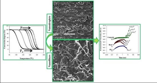
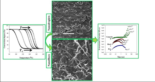
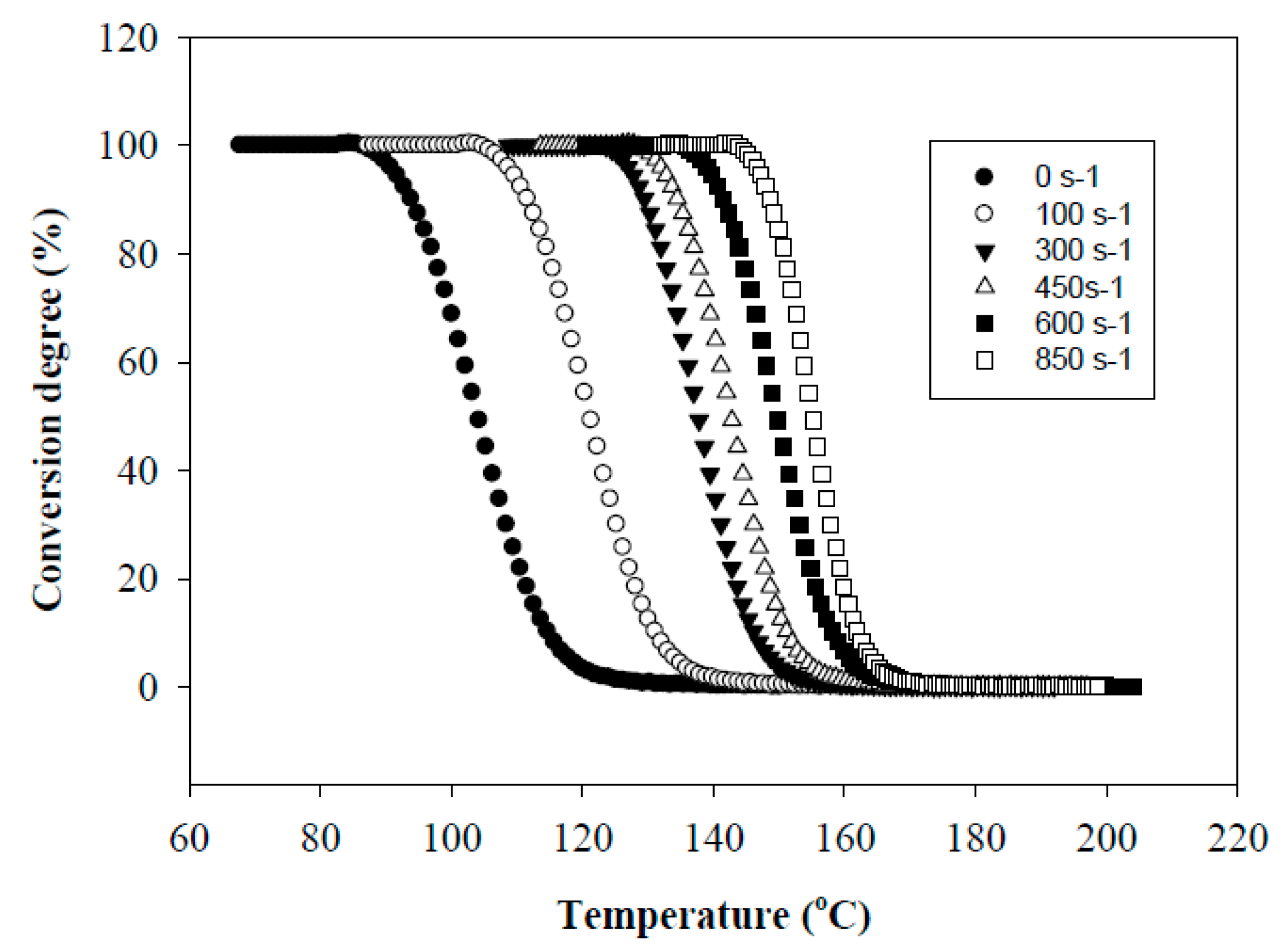
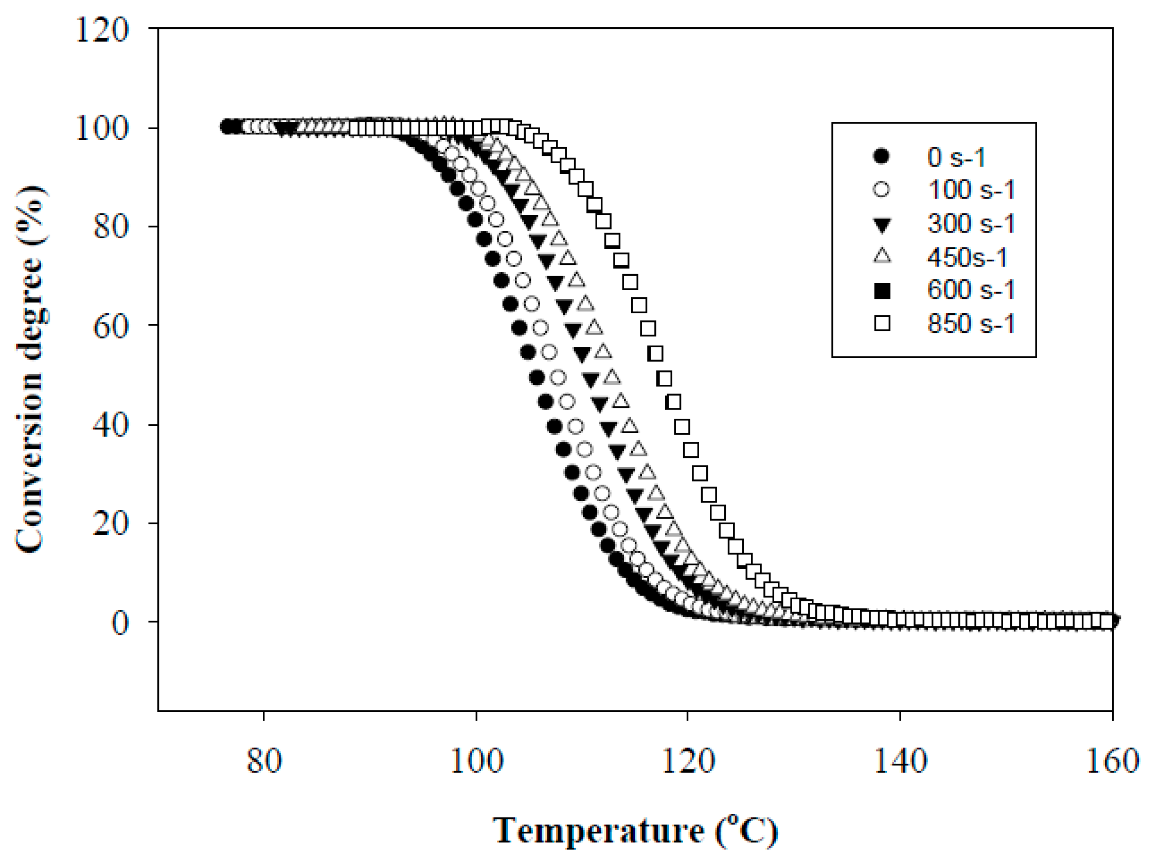
Figure 1 shows the effect of the shear rate γ on the conversion degree of PHA. It is seen that as the shear rate increases, the crystallization temperature,
Tc, shifts towards higher temperature and the transition from a molten state to a crystallized one proceeds in a narrower temperature range, Δ
T. In particular, an increase in γ up to 300 s
−1 results in a shift of
Tc toward higher temperatures up to 137 °C and a decrease in Δ
T from 38 to 24 °C. The maximum effect is achieved at γ = 850 s
−1. In this case,
Tc is 156 °C and Δ
T = 17 °C. The shift in
Tc was smaller for the PHA sheared at constant temperature and subsequently cooled down (
Figure 2). The observed effect is due to the fact that the implementation of simultaneous shear and cooling leads to a significant reduction in the time gap between cessation of shearing and the onset of crystallization. The shorter this time gap, the less possibility for the crystal nucleus to re-melt at temperatures above non-isothermal crystallization temperature and for polymer chains to recoil and relax. An increase in the shearing rate promotes an increase in the concentration of nuclei and accelerates the crystallization process. In that way, in situ generated PHA fibers would crystallize directly under a high shear rate without the necessity for cooling below the temperature of their non-isothermal crystallization. The relaxation process minimized in this way would cause the retention of the achieved elongation degree of droplet inclusions into fibers.
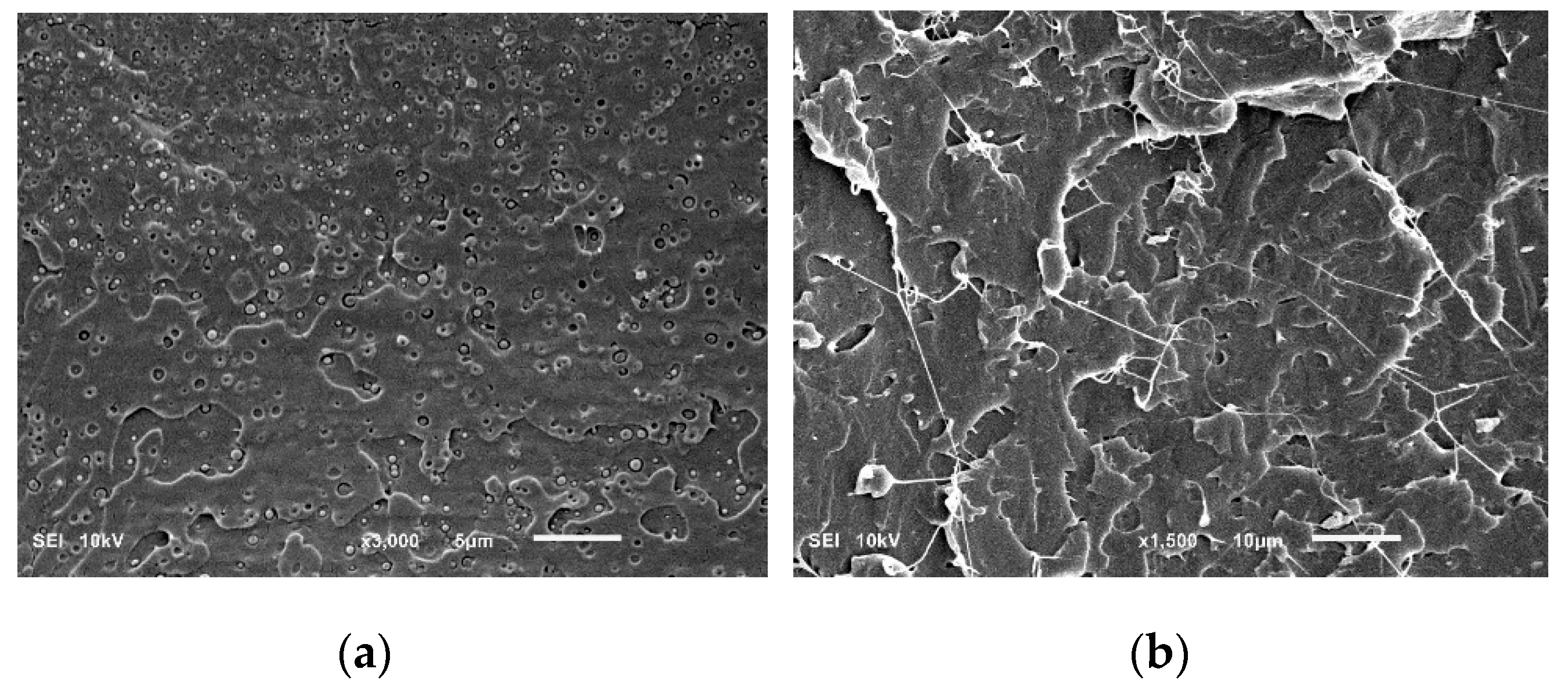
Figure 3 shows the morphologies of the cryogenically fractured surfaces of the PLA/PHA blend and in situ generated PLA/PHA composites. The PLA/PHA blend presents typical matrix–droplet morphology. PHA spherical particles and dark holes left by them during fracture are observed on the surface of the blend (
Figure 3a). The surface of these particles is smooth with clear borders, suggesting poor compatibility and weak interfacial adhesion between the PLA and PHA phases. Meanwhile, the low concentration of PHA (3 wt.%) makes their dispersion in PLA matrix well-uniform and causes the formation of nano-sized spherical particles of PHA. Most PHA dispersed phases are in the range of 50–450 nm and the averaged size is about 275 nm. Intensive blending (screw speed was 120 rpm) also contributes to the deformation and fracture of the PHA phase and minimizes agglomeration of the shear–split PHA phase.
Compared to the PLA/PHA blend, SEM micrographs of the in situ generated PLA/PHA composite reveal the presence of fibril-matrix morphology (
Figure 3b). Almost all the PHA dispersed phase particles are elongated into fibrils due to the presence of a shear force field within the area between the extruder screw and the extruder walls. Detailed mixing mechanisms of immiscible polymers are provided elsewhere [
23]. It is already well established that when dispersed minor polymer droplets, immersed in the immiscible matrix, are subjected to high shear rates, they tend to deform and extend into long thin threads. As a result, particle radius decreases while the capillary instabilities at the interface increase. When the capillary number approaches to the critical value, the elongated nanofibrils tend to disintegrate and break up. The most important mechanisms, depending on the viscosity ratio and the degree of elongation, could be the growth of uniform Rayleigh disturbances in the middle part of the thread, end-pinching at the ends, and necking. However, rapid solidification caused by shear induced crystallization prohibits these time-dependent transformations. Thus, continuously elongated in the melt, PHA nanofibrils are stabilized and fixed by crystallization before they may undergo any retraction or disintegration.
This is reasonable because the viscosity ratio between the PLA/PHA blend and neat PLA at low temperatures is, according to [
24], in the optimum range, which is (0.1:10), and remains within this range despite the shear thinning which occurs at high shear rates, that is the hydrodynamic force overcomes the cohesive strength of the dispersed PHA droplets (shown in the
Supplementary Material, Figure S1). It is also well known that fibrous droplets could eventually take the form of spherical ones or break up into small particles by interfacial tension, but rapid solidification prohibits these transformations and results in fibrous dispersion.
The final nanofibers are 70–130 nm in diameter and form the physical network structure. The formation of the physical network of PHA in the PLA matrix is possible during compounding and not during extensional flow in the slit die zone. Apparently, the slit capillary serves as a dumping for the flow and to increase the residence time in the extruder and facilitate the formation of fibril entanglements. The ratio of the diameters of the fibrils to the droplets shows that the aspect ratio of PHA fibrils is at least 100. Since the exact length of the fibers is unclear, it can be assumed that the actual aspect ratios of PHA fibrils can be even larger because of weak interfacial adhesion between the PLA and PHA phases and a uniform distribution of PHA nanoparticles, which increase the probability of them coalescing during shearing, and thereby facilitate formation of very long fibrils. The dispersed PHA fibrils show tight contact with the PLA matrix, leaving no distinct voids between the elongated fibers and the matrix. This fact indicates a good adhesion between the fibrils and the matrix.
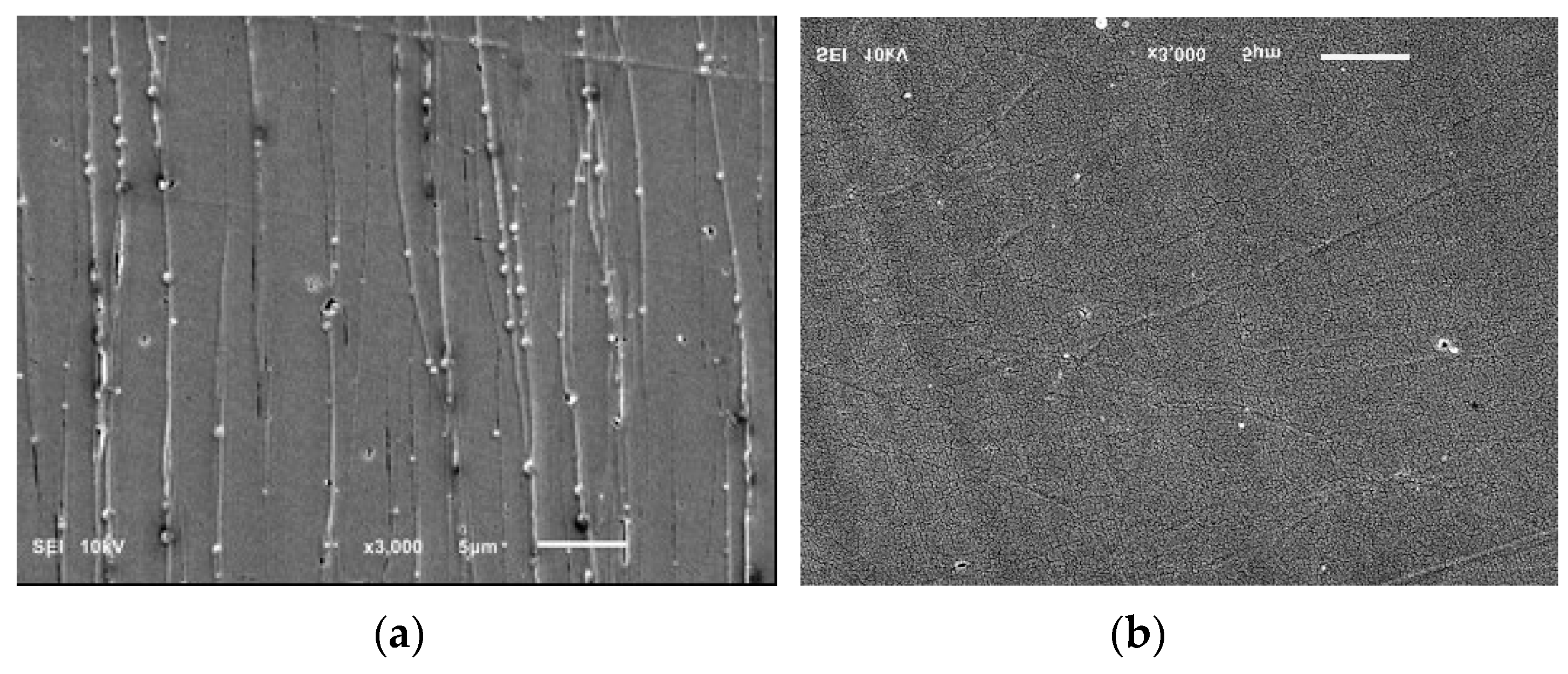
The SEM micrograph analysis of the PLA/PHA composite in longitudinal and transverse sections shows the uniform distribution of the microfibrils, and nearly the same number of revealed fibrils in both sections indicates the possibility of forming a physical network structure (
Figure 4).
According to [
25], 2.5 wt.% of the minor phase corresponds to the gelation point at which physical network structure forms. To verify this assumption, the viscoelastic behavior of the PLA/PHA blend and in situ generated PLA/PHA composites were examined.
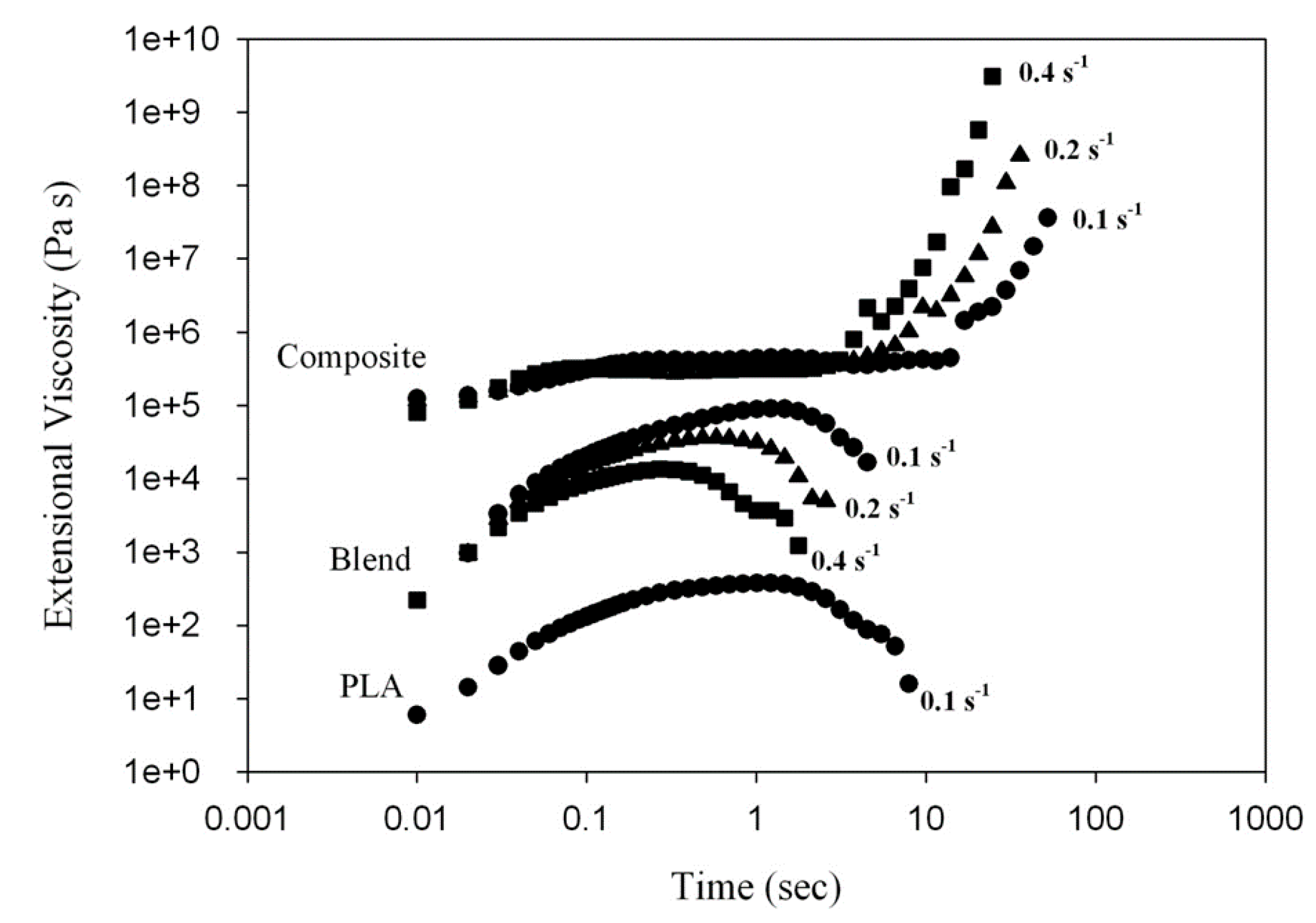
Figure 5 presents a time-dependence of the tensile stress growth coefficient,
(t, έ), for molten PLA, PLA/PHA blend and composite recorded during uniaxial tension at various Hencky strain rates, έ. For neat PLA and the PLA/PHA blend,
(t, έ) gradually increases with time, t, but it is nearly independent of έ. The monotonic stress growth reflects a predominantly plastic flow. The tensile stress growth coefficient,
(t, έ), then reaches the end of plateau when the chains become highly extended. At and beyond this plateau, chains could start to slide past one another at the entanglement points causing yielding of the entanglement network and the appearance of a strain softening effect. As the number of load-bearing entanglements decreases, the tensile stress growth coefficient,
(t, έ), is reduced as shown in
Figure 5.
In contrast to neat PLA and the PLA/PHA blend, exhibiting no strain hardening itself, the in situ generated PLA/PHA composite containing a PHA fiber network structure demonstrates a significant increase of (t, έ) above the linear viscoelastic region during uniaxial extensional deformation. This is because the PHA fiber network, containing physical entanglements between the fibers, is deformed during uniaxial extension causing such an upward deviation of (t, έ) for the PLA/PHA composite, known as strain hardening.
An important condition of effective conversion of the droplets of the minor polymer into fibers is the immiscibility of polymer constituents. According to the DSC analysis of the PLA/PHA extruded nanocomposite, melting of 3 wt.% of PHA is evidenced by a small endothermic peak at around 170 °C (shown in the
Supplementary Material, Figure S2). The glass transition of the PLA matrix is seen at around 60 °C with an enthalpy relaxation signal caused by PLA orientation. The separate melting peak of PHA crystals proves that PHA is not miscible with PLA.
A similar conclusion about the immiscibility of PLA and PHA can be drawn based on E
// data from DMTA measurements of PLA/PHA extruded tapes (shown in the
Supplementary Material, Figure S3). The E
// peak at the PLA glass transition is not shifted for the PLA/PHA nanocomposite and the glass transition of PHA is not discernible at –17 °C because of the low concentration of PHA (3 wt.%).
The morphology of the dispersed phase plays an important role in achieving improved mechanical properties of polymer blends or composites. In the case of the PLA/PHA blend, the spherical PHA particles with a diameter ranging between 50 and 450 nm were found to be distributed in the PLA matrix, which indicates a completely immiscible blend. Additionally, the PHA particles exhibited a uniform dispersion in the PLA matrix. The morphology of immiscible phases is also observed in the case of the PLA/PHA composite, with fibers with a diameter of 70–130 nm and an aspect ratio of not less than 100. As a result, for the PLA/PHA blend, the Young modulus, stress at break, and elongation at break exceeded the related parameters of neat PLA by 5%, 28%, and 6% (2.14 GPa, 55.0 MPa, and 7.4%), respectively. In the case of the in situ generated PLA/PHA composite chatacterized by fibrillar morphology, the Young modulus, stress at break, and elongation at break exceeded the related parameters of neat PLA by 15%, 30%, and 400% (2.35 GPa, 56.0 MPa, and 28.1%), respectively. This could be explained by the presence of PHA nanoparticles in the PLA matrix, which restrict the mobility of PLA chains and thus improve the stiffness of the PLA matrix. Moreover, the absence of signs of aggregation of the PHA nanoparticles in the PLA matrix i.e., the homogeneous dispersion of the nanoparticles, leads to a more regular and stronger structure of the blend, thereby improving the interfacial integrity of PLA and PHA to better transfer the stress under external force [
26]. However, the much larger reinforcing effect, in the case of the PLA/PHA composite, is caused by the more extensive load-bearing capacity of the long PHA nanofibrils forming the network as well as the existence of larger interfacial areas between the nanofibers and the matrix. The main contribution to a significant increase in elastic and strength properties is associated with the formation of the PHA nanofibril network. This clearly demonstrates the dependences of true stress as a function of the Hencky strain after subtracting the data for neat PLA from respective stress–elongation curves for the nanocomposite (
Figure S4 in Supplementary Materials). It is revealed that the nanofibril’s response is weak for small strains. However, exceeding the strain of 0.5, a strong strain hardening occurs which could be attributed to the straining of the network of PHA entangled nanofibers.
The formation of PHA nanofibers may also be responsible for an essential increase in the ductility of the PLA matrix. These PHA nanofibers, along with PLA nanofibers spanning the craze surfaces, dissipate a large amount of energy until they break, providing a continuous crack nano-bridge toughening right before the crack front.
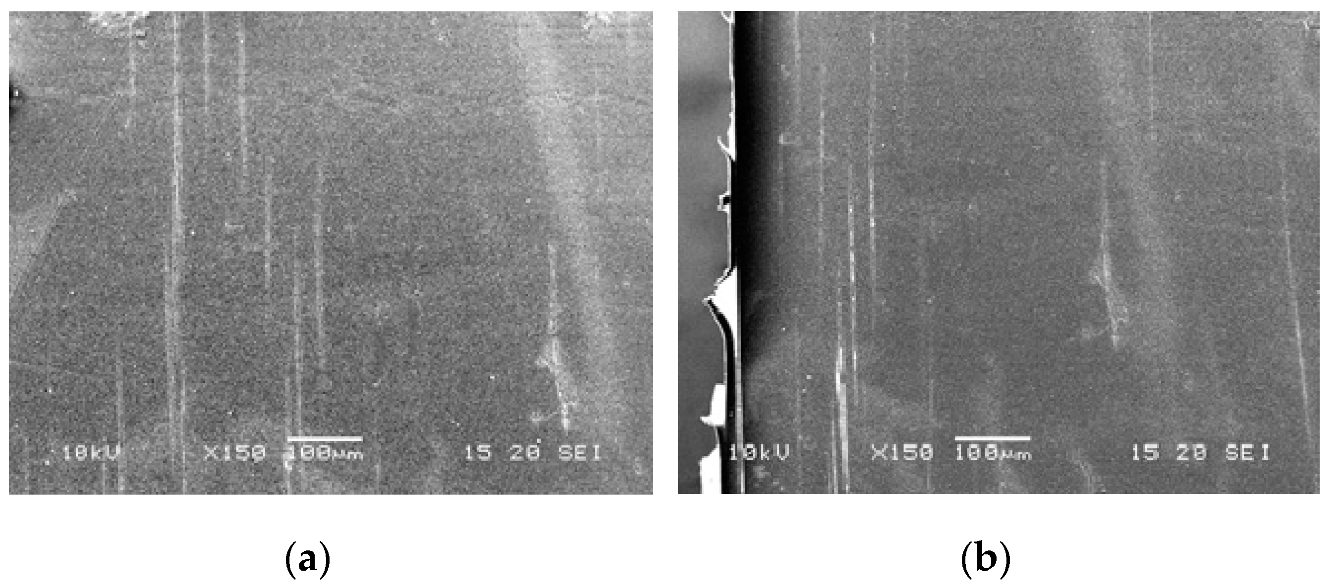
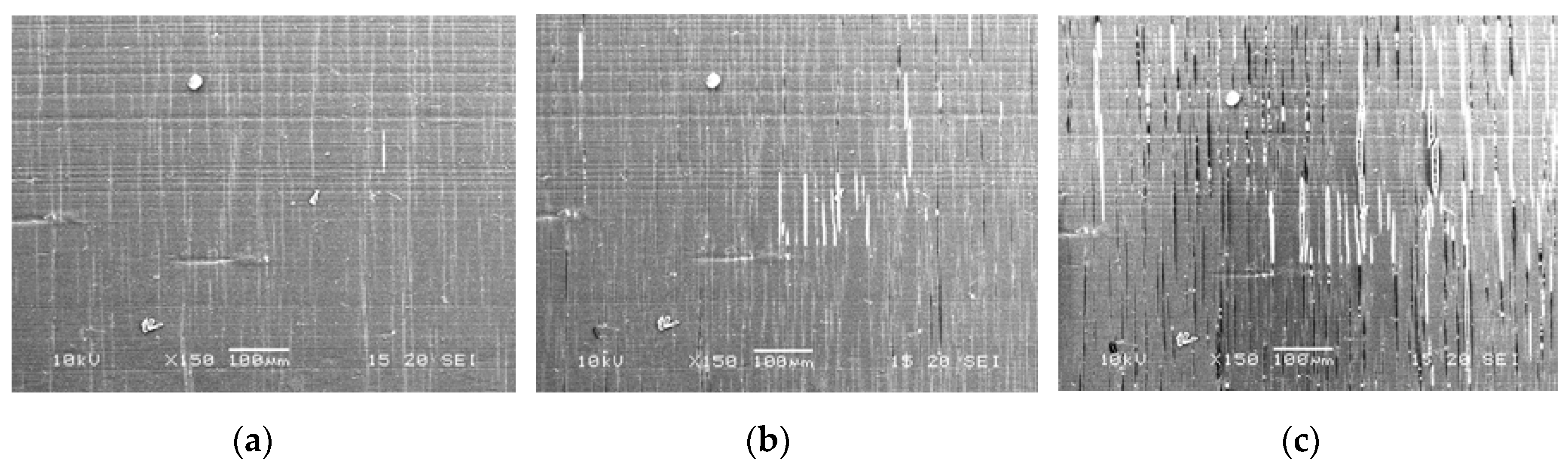
Figure 6 and
Figure 7 show the SEM images of crazes for the PLA/PHA blend and composite. For neat PLA, the crazes are thin, 1–2 μm, and do not thicken until failure [
11]. Crazes in the PLA/PHA blend are almost the same size, 1–4 μm (
Figure 6). The slightly larger craze size is due to the fact that the PHA nanoparticles may toughen the matrix and facilitate the PLA nanofibers’ formation during the development of crazes. However, for the PLA/PHA composite, crazes thicken with increasing strain up to a few tens of μm (
Figure 7).
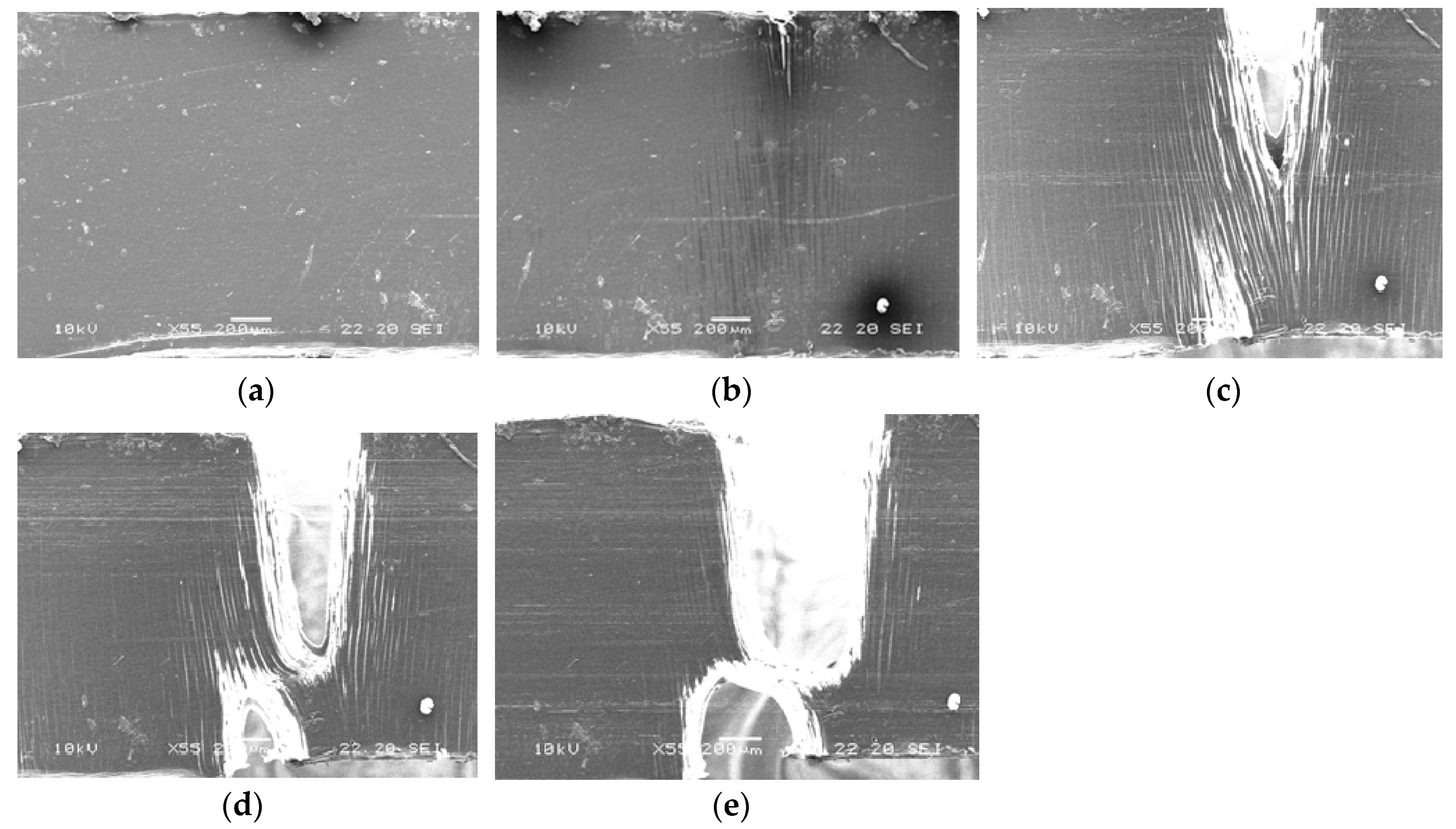
It has been shown in our previous paper [
11] that neat PLA demonstrates a quite brittle fracture with severe localization of strain before yielding. The addition of 3 wt.% PHA to PLA increases the number of crazes. Despite some crack nano-bridge toughening by PLA nanofibers, which makes it possible to transfer loads to the rest of the material and avoid overloading heavily loaded crazes, the deformation mechanism remains crazing. Nevertheless, a certain amount of crazes provides some load-bearing capacity and leads to the improvement of the ductility of PLA/PHA blends. For the PLA/PHA composite, a neck appears after yielding. In the initial stages of deformation (e ≤ 0.20), intensive crazing is observed, but then at higher values of deformation (e > 0.22), crazing is replaced by the plastic flow of the material (
Figure 8).
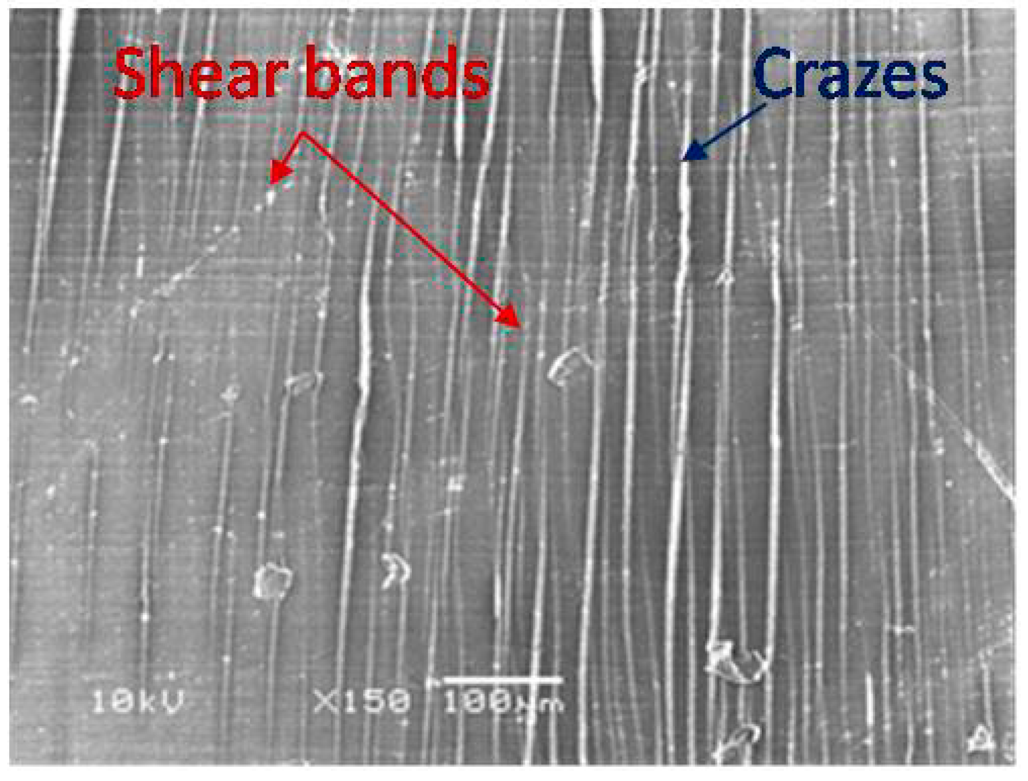
It is known that neat PLA exhibits a strong strain softening, which stimulates strain localization and causes the build-up of local tri-axial stress. Since the local strain of neat PLA could not be delocalized, the local tri-axial stresses will induce void nucleation and crazes in the matrix leading to a brittle fracture behavior [
27,
28]. In the PLA/PHA blend, as well as the PLA/PHA composite, these tri-axial stresses could be released via intensive crazing i.e., the local strain in the PLA matrix would be delocalized. At a certain density of these crazes, the stress state in the PLA matrix could be converted from tri-axial to uni-axial. The new stress state is favorable for the initiation of shear bands leading to shear yielding of the matrix, as can be seen in
Figure 9. Such a change in deformation mode from crazing to shear yielding was observed by us for the PLA/PBS system [
11].


