Design of a Bicycle Head Lamp Using an Atypical White Light-Emitting Diode with Separate Dies


 ,
, 
Abstract
1. Introduction
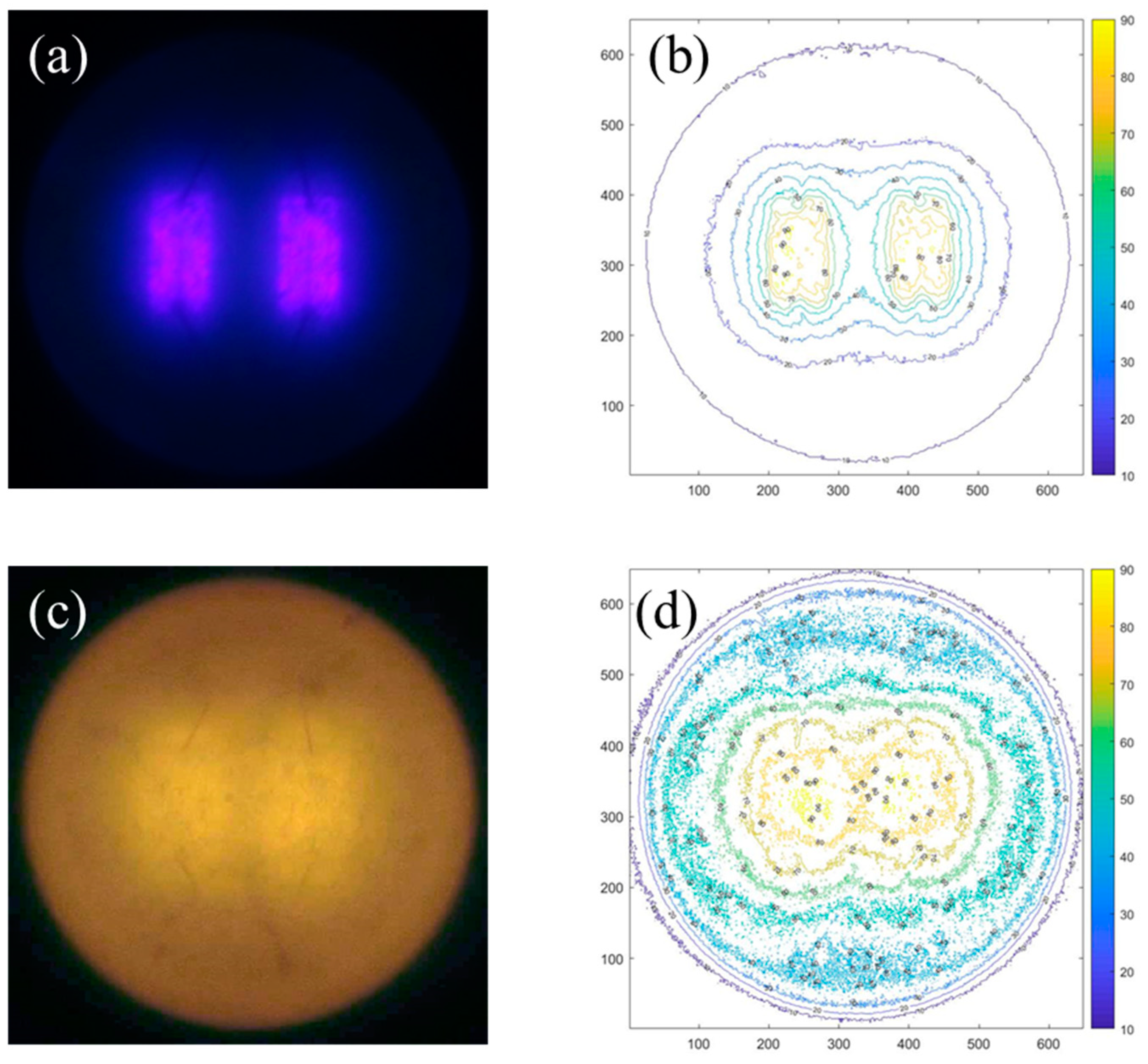
2. Optical Modeling
3. Optical Design
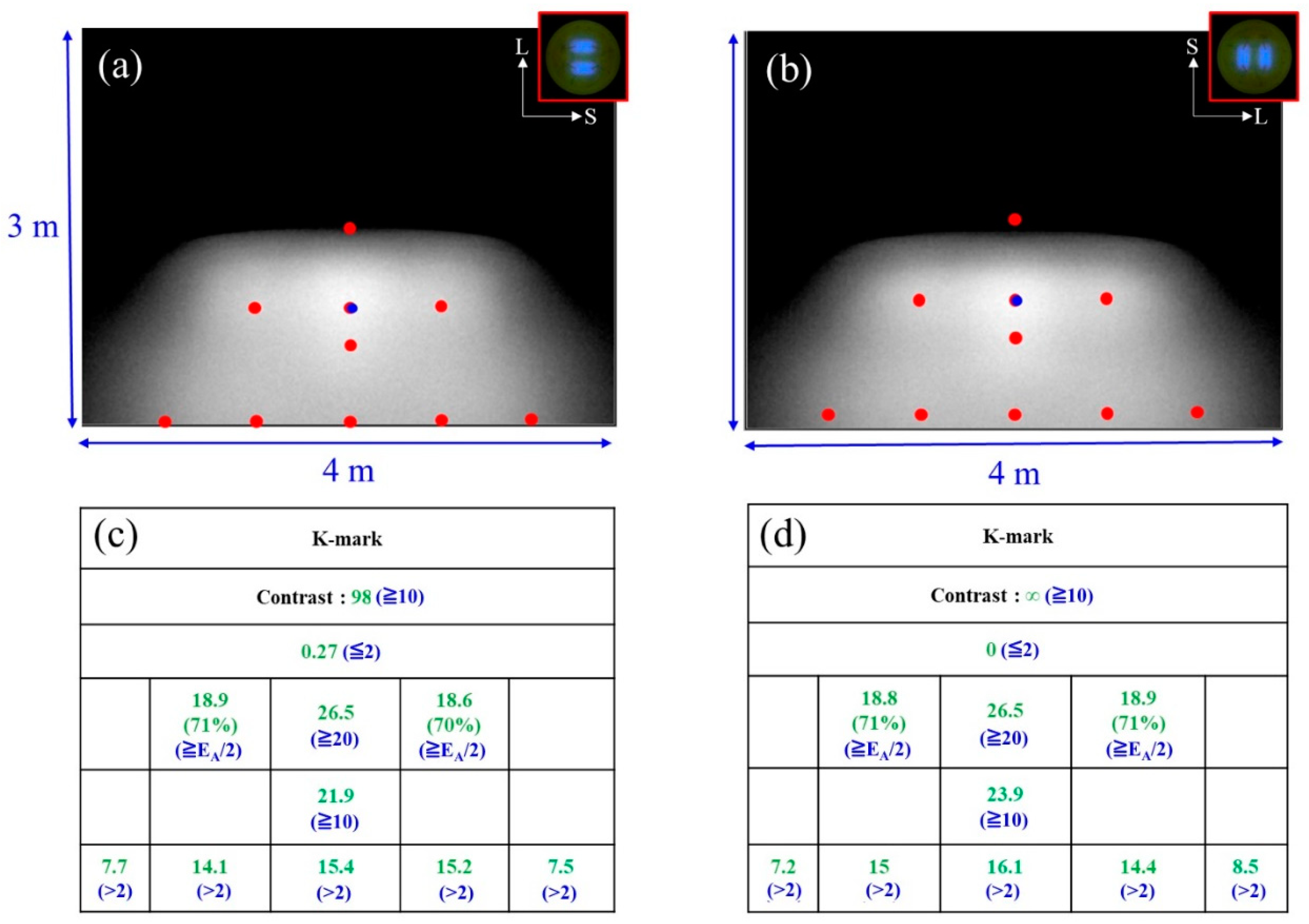
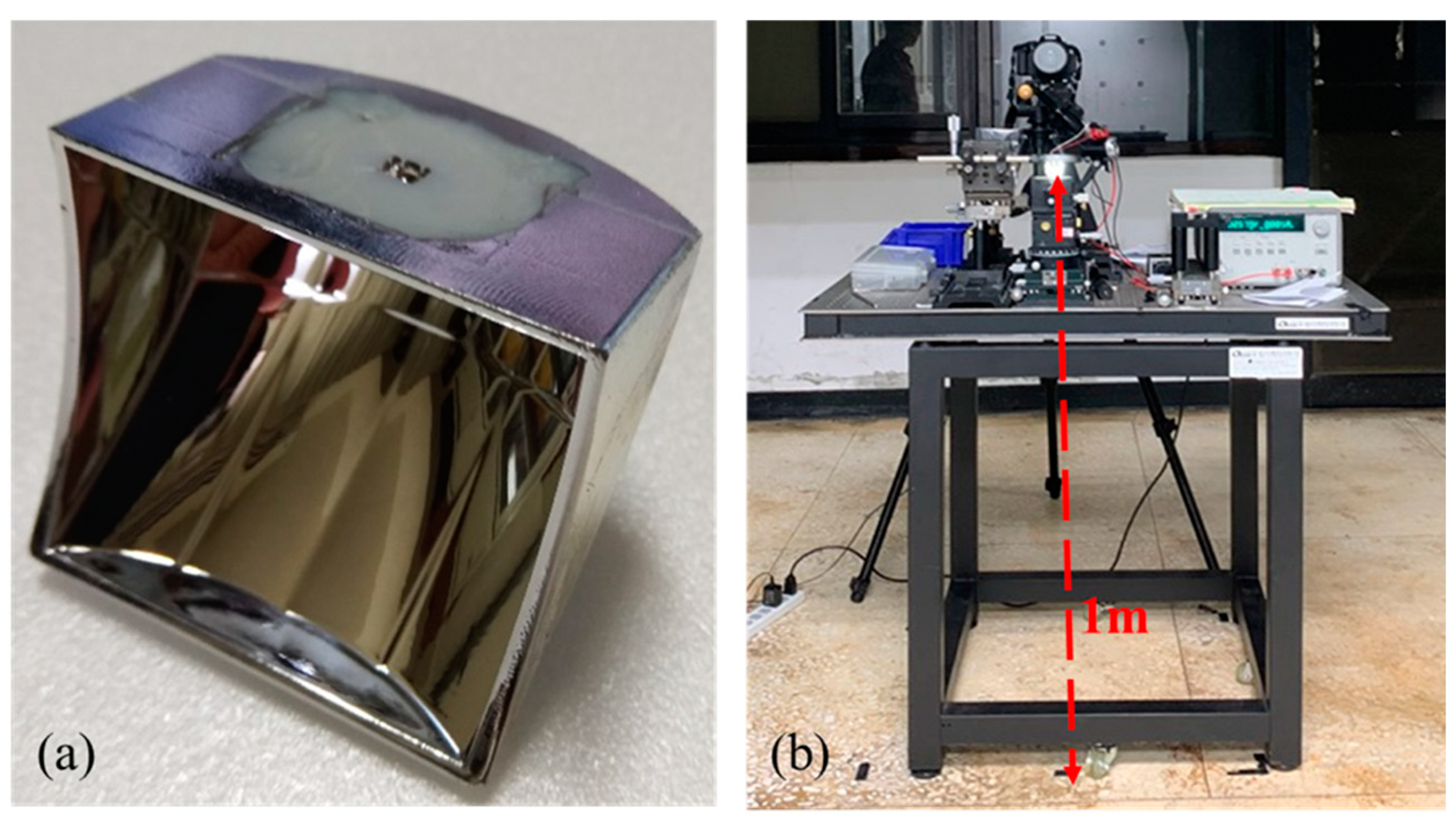
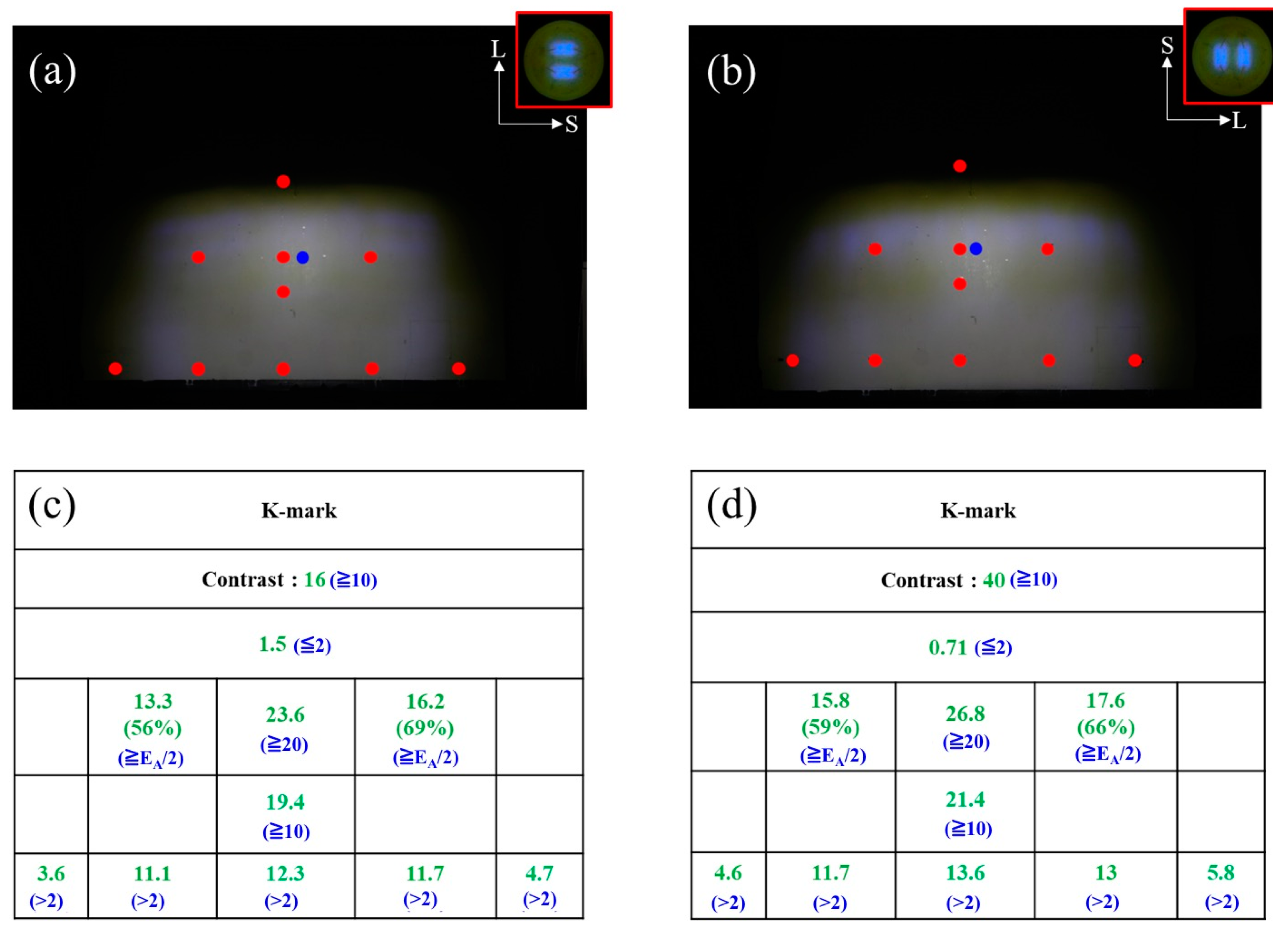
4. Experimental Verification
5. Discussion
6. Conclusions
Author Contributions
Funding
Acknowledgments
Conflicts of Interest
References
- ISO 6742-12015—Estonian Centre for Standardisation. Available online: https://www.evs.ee/products/iso-6742-1-2015 (accessed on 4 December 2019).
- United Nations Economic Commission for Europe Vehicle Regulations. ECE R112. Available online: http://www.unece.org/fileadmin/DAM/trans/main/wp29/wp29regs/r112r1e.pdf (accessed on 4 December 2019).
- Cvetkovic, A.; Dross, O.; Chaves, J.; Benítez, P.; Miñano, J.C.; Mohedano, R. Etendue-preserving mixing and projection optics for high-luminance LEDs, applied to automotive headlamps. Opt. Express 2006, 14, 13014–13020. [Google Scholar] [CrossRef] [PubMed]
- Chen, F.; Wang, K.; Qin, Z.; Wu, D.; Luo, X.; Liu, S. Design method of high-efficient LED headlamp lens. Opt. Express 2010, 18, 20926–20938. [Google Scholar] [CrossRef] [PubMed]
- Ge, A.; Wang, W.; Du, Z.; Qiu, P.; Wang, J.; Cai, J. High-energy-efficiency optical system for an LED-based headlamp architecture. Appl. Opt. 2013, 52, 8318–8323. [Google Scholar] [CrossRef] [PubMed]
- Hsieh, C.C.; Li, Y.H.; Hung, C.C. Modular design of the LED vehicle projector headlamp system. Appl. Opt. 2013, 52, 5221–5229. [Google Scholar] [CrossRef]
- Wang, H.; Wang, X.; Li, Y.; Ge, P. Design of a newly projected light-emitting diode low-beam headlamp based on microlenses. Appl. Opt. 2015, 54, 1794–1801. [Google Scholar] [CrossRef]
- Wu, H.; Zhang, X.M.; Ge, P.; Yu, J.D. A high-efficiency freeform reflector for a light-emitting diode low-beam headlamp. Light. Res. Technol. 2016, 48, 1005–1016. [Google Scholar] [CrossRef]
- Chen, H.C.; Zhou, J.H.; Zhou, Y. Stacking illumination of a confocal reflector light emitting diode automobile headlamp with an asymmetric triangular prism. Appl. Opt. 2017, 56, 1087–1093. [Google Scholar] [CrossRef]
- Sun, W.S.; Tien, C.L.; Lo, W.C.; Chu, P.Y. Optical design of an LED motorcycle headlamp with compound reflectors and a toric lens. Appl. Opt. 2015, 54, E102–E108. [Google Scholar] [CrossRef]
- Lo, Y.C.; Chen, C.C.; Chou, H.Y.; Yang, K.Y.; Sun, C.C. Design of a bike headlamp based on a power white-light-emitting diode. Opt. Eng. 2011, 50, 080503. [Google Scholar] [CrossRef]
- Lo, Y.C.; Cai, J.Y.; Chen, C.W.; Sun, C.C. A compact bike head lamp design based on a white LED operated at one watt. Opt. Laser Technol. 2012, 44, 1172–1175. [Google Scholar] [CrossRef]
- Cai, J.Y.; Lo, Y.C.; Feng, S.T.; Sun, C.C. Design of a highly efficient LED-based bicycle head lamp with additional ground illumination. Light. Res. Technol. 2014, 46, 747–753. [Google Scholar] [CrossRef]
- Park, H.J.; Lee, D.K.; Lee, J.M.; Park, K.W.; Joo, J.Y.; Kwak, J.S. Design of LED bicycle headlamp with a horizontally wide viewing angle. Curr. Opt. Photonics 2017, 1, 351–357. [Google Scholar]
- Tsai, M.S.; Sun, C.C.; Yang, T.H.; Wu, C.S.; Lin, S.K.; Lee, X.H. Robust optical design for high-contrast cut-off line in vehicle forward lighting. OSA Contin. 2019, 2, 1080–1088. [Google Scholar] [CrossRef]
- Narendran, N.; Maliyagoda, N.; Bierman, A.; Pysar, R.; Overington, M. Characterizing white LEDs for general illumination applications. Proc. SPIE 2000, 3938, 240–248. [Google Scholar] [CrossRef]
- Steigerwald, D.A.; Bhat, J.C.; Collins, D.; Fletcher, R.M.; Holcomb, M.O.; Ludowise, M.J.; Martin, P.S.; Rudaz, S.L. Illumination with solid state lighting technology. IEEE J. Sel. Top. Quantum Electron. 2002, 8, 310–320. [Google Scholar] [CrossRef]
- Zukauskas, A.; Shur, M.S.; Caska, R. Introduction to Solid-State Lighting; John Wiley & Sons: New York, NY, USA, 2002; ISBN 978-0-471-21574-5. [Google Scholar]
- Schubert, E.F.; Kim, J.K. Solid-state light sources getting smart. Science 2005, 308, 1274–1278. [Google Scholar] [CrossRef] [PubMed]
- Schubert, E.F. Light-Emitting Diods, 2nd ed.; Cambridge University Press: New York, NY, USA, 2006; ISBN 9780521865388. [Google Scholar]
- Krames, M.R.; Shchekin, O.B.; Mueller-Mach, R.; Mueller, G.O.; Zhou, L.; Harbers, G.; Craford, M.G. Status and future of high-power light-emitting diodes for solid-state lighting. J. Disp. Tech. 2007, 3, 160–175. [Google Scholar] [CrossRef]
- Pimputkar, S.; Speck, J.S.; DenBaars, S.P.; Nakamura, S. Prospects for LED lighting. Nat. Photonics 2009, 3, 180–182. [Google Scholar] [CrossRef]
- Karlicek, B.; Sun, C.C.; Zissis, G.; Ma, R. Handbook of Advanced Lighting Technology; Springer: Basel, Switzerland, 2017; ISBN 978-3-319-00175-3. [Google Scholar]
- Sun, C.C.; Chang, Y.Y.; Yang, T.H.; Chung, T.Y.; Chen, C.C.; Lee, T.X.; Li, D.R.; Lu, C.Y.; Ting, Z.Y.; Glorieux, B.; et al. Packaging efficiency in phosphor-converted white LEDs and its impact to the limit of luminous efficacy. J. Soild State Light. 2014, 1, 19. [Google Scholar] [CrossRef]
- Chen, C.Y.; Yang, T.H.; Hsu, C.H.; Sun, C.C. High-efficiency white LED packaging with reduced phosphor concentration. IEEE Photonics Technol. Lett. 2013, 25, 694–696. [Google Scholar] [CrossRef]
- Sun, C.C.; Chen, C.Y.; Chen, C.C.; Chiu, C.Y.; Peng, Y.N.; Wang, Y.H.; Yang, T.H.; Chung, T.Y.; Chung, C.Y. High uniformity in angular correlated-color temperature distribution of white LEDs from 2800K to 6500K. Opt. Express 2012, 20, 6622–6630. [Google Scholar] [CrossRef] [PubMed]
- Sun, C.C.; Chang, Y.Y.; Wang, Y.H.; Chen, C.Y.; Lo, Y.C.; Cheng, H.H. Precise spatial-color optical modeling in phosphor-converted white LEDs. J. Disp. Technol. 2015, 11, 261–265. [Google Scholar] [CrossRef]
- Yang, T.H.; Wu, S.M.; Sun, C.C.; Glorieux, B.; Chen, C.Y.; Chang, Y.Y.; Lee, X.H.; Yu, Y.W.; Chung, T.Y.; Lai, K.Y. Stabilizing CCT in pcW-LEDs by self-compensation between excitation efficiency and conversion efficiency of phosphors. Opt. Express 2017, 25, 29287–29295. [Google Scholar] [CrossRef]
- Chien, W.T.; Sun, C.C.; Moreno, I. Precise optical model of multi-chip white LEDs. Opt. Express 2007, 15, 7572–7577. [Google Scholar] [CrossRef] [PubMed]
- Sun, C.C.; Lee, T.X.; Ma, S.H.; Lee, Y.L.; Huang, S.M. Precise optical modeling for LED lighting verified by cross correlation in the midfield region. Opt. Lett. 2006, 31, 2193–2195. [Google Scholar] [CrossRef] [PubMed]
- Sun, C.C.; Chien, W.T.; Moreno, I.; Hsieh, C.C.; Lo, Y.C. Analysis of the far-field region of LEDs. Opt. Express 2009, 17, 13918–13927. [Google Scholar] [CrossRef]
- Lewis, J.P. In Vision Interface 95. Can. Image Process. Pattern Recognit. Soc. 1995, 95, 120–123. [Google Scholar]


© 2019 by the authors. Licensee MDPI, Basel, Switzerland. This article is an open access article distributed under the terms and conditions of the Creative Commons Attribution (CC BY) license (http://creativecommons.org/licenses/by/4.0/).
Share and Cite
Lin, H.-J.; Sun, C.-C.; Wu, C.-S.; Lee, X.-H.; Yang, T.-H.; Lin, S.-K.; Lin, Y.-J.; Yu, Y.-W. Design of a Bicycle Head Lamp Using an Atypical White Light-Emitting Diode with Separate Dies. Crystals 2019, 9, 659. https://doi.org/10.3390/cryst9120659
Lin H-J, Sun C-C, Wu C-S, Lee X-H, Yang T-H, Lin S-K, Lin Y-J, Yu Y-W. Design of a Bicycle Head Lamp Using an Atypical White Light-Emitting Diode with Separate Dies. Crystals. 2019; 9(12):659. https://doi.org/10.3390/cryst9120659
Chicago/Turabian StyleLin, Hsin-Jung, Ching-Cherng Sun, Chi-Shou Wu, Xuan-Hao Lee, Tsung-Hsun Yang, Shih-Kang Lin, Yi-Jou Lin, and Yeh-Wei Yu. 2019. "Design of a Bicycle Head Lamp Using an Atypical White Light-Emitting Diode with Separate Dies" Crystals 9, no. 12: 659. https://doi.org/10.3390/cryst9120659
APA StyleLin, H.-J., Sun, C.-C., Wu, C.-S., Lee, X.-H., Yang, T.-H., Lin, S.-K., Lin, Y.-J., & Yu, Y.-W. (2019). Design of a Bicycle Head Lamp Using an Atypical White Light-Emitting Diode with Separate Dies. Crystals, 9(12), 659. https://doi.org/10.3390/cryst9120659