Abstract
A new LED rear light for automotives is proposed and demonstrated for EU ECE R07 regulation. The full rear light is a combination of a position lamp and a braking lamp, and LED light bars and micro-prisms are involved as their essential components. The micro-prisms are applied to homogenize the output of the rear light to decrease glare and accomplish EU ECE standard. Through experiments, it is shown that EU ECE R07 regulation can be met in the proposed rear light, and 12% (position lamps) and 26.5% (braking lamps) higher candela can be enhanced after the optimization of micro-prisms.
1. Introduction
Nowadays, the applications of Light Emitting Diode (LED) technology not only have played a major role in general lighting, but also extended its applications in the automotive industry [1,2]. In the automotive field, the LED light has been used for illumination by head lamp and for conspicuity by signal lamps and identification lamps [2,3]. However, the traditional technology that makes use of direct lighting with arrays of LEDs and reflective optics in conspicuous lights of automotives usually causes non-uniform brightness and glare problems [4,5], as shown in Figure 1a. In consequence, the conventional LED conspicuous automotive light typically causes glare to night drivers, which elevates the danger of traffic. In order to solve the above problems, several new design ideas for car signal lights have been proposed [6,7,8,9]. For example, the indirect light installed with a micro-prism sheet and LED [1,2,3,4,5,6], which is more promising and has been used to construct an automotive rear light with an attractive pattern, as shown in Figure 1b, not only providing a smooth lighting surface, flexibility of shape, but also reducing the amount of LEDs used [10,11,12,13]. Using the technology of micro-prisms films covering the surface of the signal light changed the direction of the output light to provide a more uniform illumination surface and high efficiency. It ensures that the signal light not only improves the intensity and the uniformity of the light output but also reduces the production cost for a commercial product, compared with traditional design. The output light is evenly distributed with a larger distribution area, which reduces the glare of the signal lights, thereby increasing the safety of drivers when they drive at night.
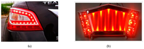
Figure 1.
The combination lamp of the car with LED technology (a) the traditional design; (b) the new design with three dimensional lighting array.
In this study, instead of using an LED point source array or indirect lighting with a micro-prisms sheet in the design of the automotive rear light, a new automotive rear LED light using a micro-prism array device is proposed and demonstrated to pass EU ECE R07 regulation. The rear light is a constitutes a position lamp and a braking lamp, capable of being with flexible shape and gorgeous outlook. An LED light bar and a micro-prism array device act as the central components to yield a uniform illumination surface and high efficiency. Through the optimization of micro-prisms using a global iteration searching method, not only can a 12% (rear position lamps) and 26.5% (braking lamps) higher optical intensity be achieved, comparing the approach of LED array direct lighting, but also the EU ECE R07 standard can be reached.
2. Optics Design and Simulation Experiments
Most of the automotive lights have to comply with photometric regulation. For ECE R07 regulations of a rear light, the maximum value cannot exceed 140 candela. As to the minimum values, they are defined in Figure 2a,b for a position lamp and braking lamp, respectively, with respect to the specific directions.

Figure 2.
The photometric testing requirement of ECE R07 standard. (a) Braking lamps; (b) rear position lamp.
The proposed rear light includes a position lamp and a braking lamp, which are both constructed by one layer of LEDs and one layer of micro prism array, as shown in Figure 3 [14,15,16]. The prism array is located on the upper side of the LED layer to converge the light directions of the LED and decrease the optical glare from the LED emitting surface. The design is similar to the direct backlighting used in flat panel display technology, so it has the advantages of lower power consumption, good thermal design and excellent scalability of the thickness [17,18].

Figure 3.
The structure of the proposed automotive rear light.
The prisms array works like an array of cylindrical convex lenses, so it can replicate each LED of a rear light as a line of its virtual images. In consequence, if a LED light bar is used, multiple line source images will be formed and overlapped each other. The glare incurred by the high brightness of the LED point source will thus be decreased. Besides, the prism array can condense the divergent light from each LED to increase the optical intensity within a certain angle. The efficiency of the rear light is enhanced as a result. The behavior of LED light that has interacted with the prism sheet is illustrated in Figure 4. Of the light rays emitted from the LED module, the angle α was defined by the values which are refracted by the ray parallel with the end surface of the prisms sheet, and this angle is given by Equation (1)
where nw is the refractive index. These rays are incident on the upper surface of the prism at an angle β = π/2 − α; where nwsin(β) > 1. The condition of a prisms sheet must have a refractive index in the range nw > 1.4.
nwsin(α) =1
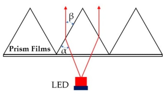
Figure 4.
The interaction of light rays with the prism sheet.
The prism sheets are provided for the purpose of condensing the light rays emitted from the source. As shown in Figure 5a, the behavior of light rays in the prism sheet can be classified into three modes: an emission mode in which light is emitted from the upper surface, a recursion mode in which light is reflected back through the prism sheet and a high-angle mode in which light is emitted outside the effective field of view. Each triangular unit in the prisms sheet is defined by the basic parameters shown in Figure 5b. Where: ϕ, θ are the inside corner value of each triangle unit (0 < ϕ = θ < 90°), h is the thickness parameter (0.05 mm to 0.25 mm), x is the pitch parameter (0.024 mm to 0.05 mm).
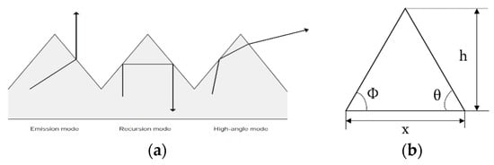
Figure 5.
(a) behavior of light rays in the prisms layer; (b) the parameter of a unit of prism.
In order to evaluate the performance of the commercial rear position lamp shown in Figure 6a, its optical model is built by SolidWork software and simulated by optical software LightTools to get the illumination distribution shown in Figure 6b and ensure it is more uniform on the output surface. The used light source is an LED light bar with nine pieces of 18.5 lumens white Lambertian LEDs and a diffusive plastic plate was used as the lamp window, which was located 30 mm from the LEDs. In order for simulation comparisons with the commercial rear position lamp, the proposed rear position lamp adopts the same LED light bar and is designed as shown in Figure 6c. The distance between neighboring LEDs is 15 mm and the prism array layer is located on the top surface, 30 mm from the LED. The inside corner angle of the prism element and pitch is set as ϕ = 60°, θ = 60° and x = 0.05 mm at the initial stage, respectively.
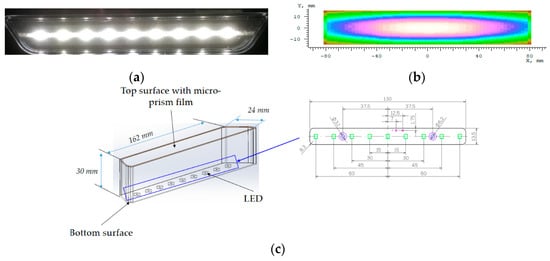
Figure 6.
(a) The conventional rear position lamp sample; (b) the simulated illumination distribution of the conventional rear position lamp; (c) the design drawing of the proposed rear position lamps.
In order to enhance the light intensity within the directions specified by ECE R07 regulation shown in Figure 2b and the luminance uniformity of the new rear position lamp, which prism array device was optimized by LighTools optical software, which ϕ and θ served as the variable parameter and both were set as 60° at the initial optimization step. The targets of optimization were set to require the new rear position light can not only accomplish the EU ECE 07 regulation, but also perform even better than the commercial one in terms of optical intensity and optical uniformity. The optimization process followed the flow charts shown in Figure 7. The effect of the prism array device on the required lamps luminance is shown in Equation (2).

Figure 7.
The flowchart of (a) the proposed rear light simulation; (b) the prism structure optimization.
In the initial optimization process, the required intensity of the new rear position lamp Iprism is calculated from the required luminance and the display area, shown in Equation (3). The mathematical equation for the viewing angle ϕ needs to be known. All the light emitted from the prism is contained within this angle ϕ. The luminous flux can be calculated with Equations (4) and (5).
where: Iprism is the intensity (cd) from the micro-prism sheet, Ω is the solid angle (sr), shown in Equation (5)
where: ϕ1/2 is the angle from 0° to where the intensity is 50% of the peak intensity. The optical efficiency of the backlight ηprism is defined as the luminous light output from the source through the prism sheet that is Φprism, divided by the light output of the light source into prism sheet that is Φlight source
Iprism = Lprism *A
Φprism = Iprism · Ω
Ω =2· π · (1 – cosϕ1/2)
After ending the solution searching, the optimization is terminated by the optical program, and the inside corner angle of the prism was determined: ϕ = 64° and θ = 69° at step 21 of the optimization process. The value of the merit function with respect to the iteration step is shown in Figure 8. The simulated optical intensity distribution and the illumination distribution of the new rear position lamp before and after optimization are shown, respectively, in Figure 9a–d. The simulation results of the optical intensity are shown in Figure 10, and it can be found that the light intensity value of the commercial lamp and the new optimized lamp both exceeded the requirements of ECE R07 standard. Besides, the new design has an even higher light intensity than the conventional one. Based on the data shown in Figure 6b, Figure 9 and Figure 10, it can be shown that the uniformity and the candela intensity were both elevated through the optimization. Moreover, the light output of the new design is more uniform, which would make the surface of the lamp more attractive and more luxurious. The simulated output light intensity values of the position lamps in Figure 10 showed that the highest values are at the testing angle H-5R, 119 cd for the new design and 77 cd for the commercial design. In addition, the results show the level of variation in the new design with a micro-prisms layer is slightly higher than the commercial one.
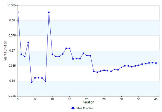
Figure 8.
The recorded value curve of merit function in the optimization process.
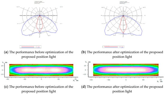
Figure 9.
(a,b) The intensity distribution of the proposed position light (c,d) The illuminance distribution of the proposed position light.
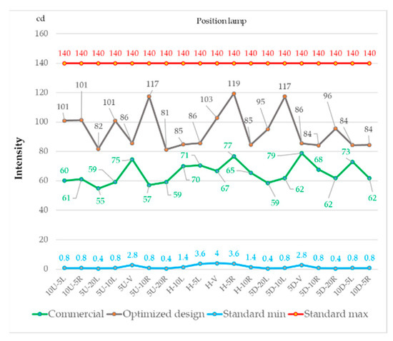
Figure 10.
The comparison of simulated optical intensity for the considered angles of EU ECE regulation between the new optimized position lamp and the commercial one.
Optical glare from LED light is mainly caused by its extremely bright emitting surface, which usually causes discomfort to the driver when looking directly at the conventional rear LED automotive lights. Based on the simulated brightness data of the LED position lamps, the commercial design is at least with 1.33 times brightness of the optimized design’s for each view angle, as shown in Figure 11. Therefore, the optimal design should have a lower glare than the commercial one. The commercial design at view angle H–V has the highest value of brightness and with the highest glare.
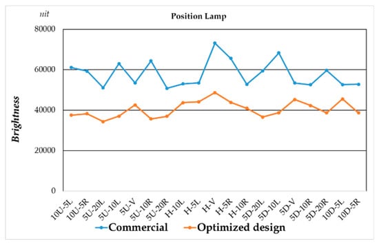
Figure 11.
The comparison of the simulated brightness result for the considered angles of EU ECE regulation between the new optimized position lamp and the commercial one.
3. Optical Experiments–Optical Measurement and Analysis
In order to evaluate the accuracy of the new optimized position lamp, it is prototyped and shown in Figure 12 and tested by the experimental setup using Goniophotometer, as shown in Figure 13. The commercial sample is provided by OWL LIGHT AUTOMOTIVE MFG. CORP (Lukang, Chunghua, Taiwan) and it has been in mass production for automotives in the Europe market. The LED light bar is used to follow the simulation condition to prepare. The driving voltage of the LED light source is 13.3 V. The experimental results, shown in Figure 14, demonstrated that the new optimized position light not only can pass the ECE regulation in the real position lamp test, but also have a higher performance in optical intensity as shown in Figure 14a and lower glare, as shown in Figure 14b, compared to the commercial design. Furthermore, a new braking lamp design was prototyped by composing 5 sets of the optimized position light and measured through the same procedure as the position lamp prototype, shown in Figure 15. The experimental results are shown in Figure 16, which shows that the new optimized braking lights work better than the commercial one and pass the ECE regulation in the braking lamp test.

Figure 12.
(a) The inner sight of the new optimized position lamp; (b) the outlook of the new optimized position lamp.

Figure 13.
Optical experiment setup for optical intensity distribution testing.
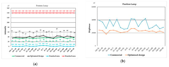
Figure 14.
The comparison with respect to each considered angle of EU ECE regulation between the new optimized position lamp prototype and the commercial sample; (a) measured optical intensity; (b) measured optical brightness.

Figure 15.
(a) The inner sight of the new optimized braking lamp; (b) the outlook of the new optimized braking lamp.
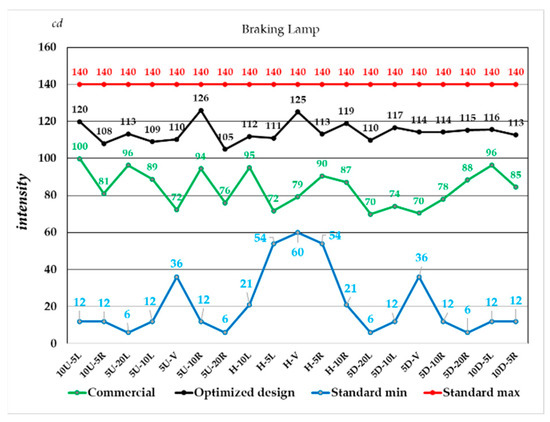
Figure 16.
The comparison of the measured optical intensity with respect to each considered angle of EU ECE regulation between the new optimized braking lamp prototype and the commercial sample.
4. Discussion
Optimal design combined with optical film has been produced a real prototype product by OWL company, shown in Figure 12a. The sample consists of a position lamp and a braking lamp. The light output pattern of the position lamps shown in Figure 12b, of the braking lamps shown in Figure 15b. The experimental results using photometric testing system are shown in Figure 14 and Figure 16. According to the result shown in Figure 14, it can be computed that the ratio of the averaged illuminance efficiency of the optimized position lamps to that of the commercial position lamps is (35.5/35.23, 10U-5L), (38.9/35.3, 10U-5R), (38.6/32.2, 5U-20L), (36.2/34.5, 5U-10L), (36.8/35.8, 5U-V), (42.7/35.2, 5U-10R), (36.1/32.8, 5U-20R), (43.7/34.6, H-10L), (35.4/42.9, H-5L), (46.3/36.2, H-V), (39.7/36.1, H-5R), (37.0/36.0, H-10R), (34.9/33.6, 5D-20L), (44.8/35.8, 5D-10L), (43.3/38.0, 5D-V), (38.3/36.9, 5D-10R), (47.7/33.6, 5D-20R), (36.4/42.0, 10D-5L) and (38.6/36.4, 10D-5R), which means 12% higher illuminance efficiency can be accomplished by the proposed new design of rear position lamps with micro-prisms films. With the braking lamps that can be computed the ratio of averaged is (119.7/99.8, 10U-5L), (107.9/81.0, 10U-5R), (113.3/96.3, 5U-20L), (109.0/88.7, 5U-10L), (110.2/72.3, 5U-V), (125.9/94.4, 5U-10R), (104.9/75.9, 5U-20R), (111.9/95.1, H-10L), (110.9/71.7, H-5L), (125.1/79.3, H-V), (113.1/90.5, H-5R), (118.8/87.2, H-10R), (109.8/69.9, 5D-20L), (116.7/74.2, 5D-10L), (114.2/70.4, 5D-V), (114.9/78.1, 5D-10R), (115.2/88.3, 5D-20R), (115.6/96.4, 10D-5L) and (112.7/84.5, 10D-5R), which means 26.5% higher illuminance efficiency can be accomplished by the proposed new design of rear position lamps with micro-prisms films.
The principle behind the design of the braking lamps is based on the principle of position lamps. Based on the experimental results shown in Figure 16, all the data shown that the lamps passed all the requirement of the R07 regulation. Moreover, the optimal design with optical films has improved the light output intensity when it is compared with commercial product. In detail, at 00 horizontals 00 vertical (H–V), the intensity of the optimized design is 21.8% higher than the commercial sample, which is also the direction which was associated with the highest value of intensity. The braking lamps also have the highest intensity value at H–V, which indicates that the highest intensity efficiency is achieved in the H–V direction. After completing the experiment with the optimal structure with the direction of light in the horizontal direction, we carried out the design of lamps with a vertical light output. The design includes position lamps, which are referred to as PS01 and PS02, then brake lamps, which consist of two types, BR01 and BR02. The output light of the position lamps is shown in Figure 17a,b. Similarly, the brake lamps have the light output shown in Figure 17c,d. All samples are optically measured and the test results are shown in Figure 18. With position lamps, the optical experimental results have proven that it can exceed the light intensity requirement of the ECE R07 standard. Referring to the analysis of the brake lamp’s test results, this result has proven it has exceeded the minimum limit of light intensity of the ECE R07 standard. However, in the BR01 model, it is slightly higher than the BR02 type, as shown in Figure 18.
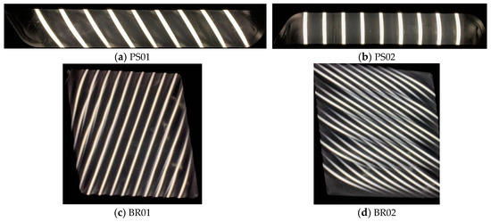
Figure 17.
The light output pattern (a,b) postion lamps; (c,d) braking lamps.
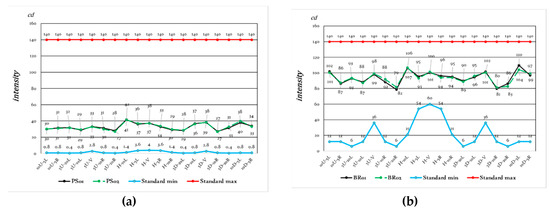
Figure 18.
The photometric testing data (a) position lamps (PS01, PS02); (b) braking lamps (BR01, BR02).
5. Conclusions
A new optimal signal lamps design, which improves the performance and uniformity of the previous commercial one is proposed. In this study, we design a new structure of taillight in which the optics films provide a smooth lighting surface and improve the illuminance uniformity. Compared with a conventional taillight, it is found that not only a 12% (rear position lamps) and 26.5% (braking lamps) higher illuminance efficiency can be achieved with the optimized taillight with optics film, but also, it meets the requirements for a taillight lamp set out by the EU ECE R07 standard. In experiments, the taillight lamp with a position lamp and braking lamp was tested, and experimental results demonstrated that it surpassed the requirement of R07 ECE regulation. Moreover, by using the technology of micro-prisms films covering the surface of the signal light, it changed the direction of the output light to create a more uniform illumination surface and high efficiency. As a result, the micro-prisms film means the signal light not only improves the intensity and the uniformity of the light output but also reduces the production cost for a commercial product, compared with traditional design. The output light is evenly distributed with a larger distribution area, which reduces the glare of the signal lights, thereby increasing the safety of drivers when they drive at night.
Author Contributions
H.-T.L. and H.-Y.L. (Hsiao-Yi Lee) carried out the experiment and wrote the manuscript with support from L.-T.L. and H.-Y.L. (Hsing-Yuan Liao) fabricated the sample and H.-Y.M. helped supervise the project. M.-J.C. and H.-Y.L. (Hsiao-Yi Lee) conceived the original idea, supervised the project. All authors have read and agreed to the published version of the manuscript.
Funding
This research was funded by Ministry of Science and Technology (MOST 108-2622-E-992-013–CC3).
Conflicts of Interest
The authors declare that they have no conflict of interest.
References
- Yu, J.C.; Chen, Z.Y.; Kao, B.D. Optical design and optimization of planar curved LED end-lit light bar. Appl. Opt. 2014, 53, H67–H75. [Google Scholar] [CrossRef] [PubMed]
- Mügge, M.; Hohmann, C. Signal lights–designed light for rear lamps and new upcoming technologies: Innovations in automotive lighting. Adv. Opt. Technol. 2016, 5, 117–128. [Google Scholar] [CrossRef]
- Chang, R.S.; Tsai, J.Z.; Li, T.Y.; Liao, H.L. LED backlight module by lightguide-diffusive component. J. Disp. Technol. 2012, 8, 79–86. [Google Scholar] [CrossRef]
- Wu, T.; Sher, C.W.; Lin, Y.; Lee, C.F.; Liang, S.; Lu, Y.; Huang Chen, S.W.; Guo, W.; Kuo, H.C.; Chen, Z. Mini-LED and micro-LED: Promising candidates for the next generation display technology. Appl. Sci. 2018, 8, 1557. [Google Scholar] [CrossRef]
- Sun, C.C.; Moreno, I.; Chung, S.H.; Chien, W.T.; Hsieh, C.T.; Yang, T.H. Brightness management in a direct LED backlight for LCD TVs. J. Soc. Inf. Disp. 2008, 16, 519–526. [Google Scholar] [CrossRef]
- Sun, C.C.; Chien, W.T.; Moreno, I.; Hsieh, C.T.; Lin, M.C.; Hsiao, S.L.; Lee, X.H. Calculating model of light transmission efficiency of diffusers attached to a lighting cavity. Opt. Express 2010, 18, 6137–6148. [Google Scholar] [CrossRef] [PubMed]
- Zhuang, Z.; Zhang, L.; Surman, P.; Guo, S.; Cao, B.; Zheng, Y.; Sun, X.W. Directional view method for a time-sequential autostereoscopic display with full resolution. Appl. Opt. 2016, 55, 7847–7854. [Google Scholar] [CrossRef] [PubMed]
- Wang, Y.J.; Ouyang, S.H.; Chao, W.C.; Lu, J.G.; Shieh, H.P. High directional backlight using an integrated light guide plate. Opt. Express 2015, 23, 1567–1575. [Google Scholar] [CrossRef] [PubMed]
- Li, C.J.; Fang, Y.C.; Cheng, M.C. Study of optimization of an LCD light guide plate with neural network and genetic algorithm. Opt. Express 2009, 17, 10177–10188. [Google Scholar] [CrossRef] [PubMed]
- Pan, J.W.; Fan, C.W. High luminance hybrid light guide plate for backlight module application. Opt. Express 2011, 19, 20079–20087. [Google Scholar] [CrossRef] [PubMed]
- Kleinkes, M.; Schmidt, C.; Mügge, M.; Hohmann, C. Sicherheit und Design künftiger Heckleuchten. ATZ-Automob. Z. 2012, 114, 70–75. [Google Scholar] [CrossRef]
- Zhang, R. Directional backlighting system using a light guide with paired microstructures. Appl. Opt. 2017, 56, 6735–6741. [Google Scholar] [CrossRef] [PubMed]
- Kimmel, J. Diffractive backlight technologies for mobile applications. J. Soc. Inf. Disp. 2012, 20, 245–258. [Google Scholar] [CrossRef]
- Van Derlofske, J.F. Computer modeling of LED light pipe systems for uniform display illumination. InSolid State Lighting and Displays. Int. Soc. Opt. Photonics 2001, 4445, 119–129. [Google Scholar]
- Yu, J.C.; Hsu, P.K. Integration of stamper fabrication and design optimization of LCD light guides using silicon-based microfeatures. Microsyst. Technol. 2010, 16, 1193–1200. [Google Scholar] [CrossRef][Green Version]
- Eichhorn, K. LEDs in automotive lighting. In Light-Emitting Diodes: Research, Manufacturing, and Applications X. Int. Soc. Opt. Photonics 2006, 6134, 613405. [Google Scholar]
- Ronny, R.A.; Knopf, G.K.; Bordatchev, E.V.; Nikumb, S. Micromilled optical elements for edge-lit illumination panels. J. Micro/Nanolithograph. MEMS MOEMS 2013, 12, 023002. [Google Scholar] [CrossRef]
- Vehicles, P.D. Concerning the Adoption of Uniform Technical Prescriptions for Wheeled Vehicles, Equipment and Parts Which Can be Fitted and/or be Used on Wheeled Vehicles and the Conditions for Reciprocal Recognition of Approvals Granted on the Basis of These Prescriptions, 2009. United Nations, Economic Commission for Europe Inland Transprot Committee. Available online: https://wiki.unece.org/download/attachments/3179169/TF-LNG-06-02.pdf (accessed on 23 January 2020).
© 2020 by the authors. Licensee MDPI, Basel, Switzerland. This article is an open access article distributed under the terms and conditions of the Creative Commons Attribution (CC BY) license (http://creativecommons.org/licenses/by/4.0/).