Article

Evolution of Microstructure, Texture and Topography during Cold Rolling and Recrystallization of Ni–5at.%W Alloy Substrate for Coated Conductors

1
Key Laboratory of Advanced Functional Materials, Ministry of Education, College of Materials Science and Engineering, Beijing University of Technology, 100 Pingleyuan, Chaoyang District, Beijing 100124, China
2
Institute of Electrical Engineering, Chinese Academy of Sciences, Beijing 100190, China
*
Author to whom correspondence should be addressed.
Crystals 2019, 9(11), 604; https://doi.org/10.3390/cryst9110604
Submission received: 2 October 2019 / Revised: 14 November 2019 / Accepted: 15 November 2019 / Published: 18 November 2019

Abstract

:
In this work, the effect of cold rolling and heat treatment upon the microstructure and texture of the surface layer and cross-section of Ni5W alloy substrate was analyzed via the EBSD technique. A typical copper deformation texture was shown by the cold-rolled Ni5W alloy substrate. The cube-oriented nuclei were attributed to the rolling direction–transverse direction (RD-TD) plane due to the presence of copper and S rolling textures. Typical large-shape cold-rolled microstructure was presented by the RD-ND surface in the cube-oriented area. During the recrystallization process, the cube-oriented grains did not have a nucleation quantity advantage, but they did have an obvious growth advantage compared with other orientation grains. They can form a strong cube texture by absorbing the random orientation and rolling orientation through the migration of large-angle grain boundaries.

1. Introduction

YBa2Cu3O7−δ(YBCO) is the second-generation high temperature superconductor exhibiting superior properties, but its brittleness hinders its application for the preparation of long wires. Based on epitaxial growth theory, the YBCO layer can be coated on a metal substrate by physical or chemical methods to obtain a coated conductor with an improved biaxial texture [1,2,3]. High quality coated conductor tapes can be prepared via superconducting thin film, and the metal substrate can support the growth of the epitaxial transition layer. The nickel alloy with 5 at. % tungsten (Ni5W) is widely used as the substrate for YBCO-coated conductors prepared via a rolling-assisted biaxially textured substrate (RABiTS) technique [4,5]. Ni5W alloy substrates have the advantages of sharp cube texture, low magnetic properties, and strong oxidation resistance. Several companies and scientific research institutes have already produced Ni5W alloy substrate, which fits the criterion of YBCO-coated conductors. Nickel with high-level fault energy gradually forms a copper-type rolling texture during rolling, mainly including S, copper, brass, and Goss orientation [6,7,8]. Low-temperature annealing was chosen in order to separate the effects of the recrystallization and grain growth of pure nickel; it was found that the cube orientation grains had a higher growth rate than the other orientation grains by a factor of ~3 [9]. The cold rolling and recrystallization textures of Ni7W and Ni9.3W substrates had already been studied by EBSD technology, which revealed that the recrystallization cube texture is strongly related to the rolling texture [10]. However, Ni5W still needs to explore the origin of the recrystallization texture, the formation mechanism of cube texture, and to elaborate on the micro-deformation texture in Ni5W alloy substrates [11,12].
This work mainly concentrates on the investigation of the microstructure and development of micro-texture during cold rolling and recrystallization in the formation mechanism of strong cube texture for Ni5W alloy substrate. Therefore, this paper mainly takes the large deformation Ni5W alloy substrate as the research object, and uses EBSD technology to visually characterize the microstructure and texture during cold rolling and recrystallization of alloy substrate, and explore the formation mechanism of strong cube texture.

2. Experiments

The Ni5W alloy ingot was prepared by vacuum induction melting. The raw materials were 99.95% pure electrolytic Ni block and 99.99% pure W block. The Ni block and the W block were mixed at an atomic percentage of 95:5. The initial ingot was obtained after heat treatment for 8 min at a temperature of 1650 °C under flowing Ar gas. After being forged and hot-rolled at a higher temperature, the ingot was subjected to a descaling treatment to obtain the average thickness of 10 mm for the initial specimen. After cutting by electron discharge machining (EDM), a size of 20 × 15 × 10 mm was obtained for the Ni5W alloy specimen. The specimen was then cold-rolled via RABiTS rolling process to obtain a Ni5W substrate with an average thickness of 75 μm. The amount of deformation at each rolling pass during cold rolling is 5% and that of the total deformation exceeded 99%. Finally, the as-rolled Ni5W substrate was isothermally treated in flowing Ar-H 24% gas at 700 °C for different times and air-cooled.
The microstructure and microscopic texture of the Ni5W alloy substrate were characterized via scanning electron microscope (SEM) equipped with electron backscattered diffraction (EBSD) accessory. Since the EBSD is very sensitive to the roughness of the sample surface, high-quality EBSD samples are necessary in order to obtain the strong Kikuchi pattern and reliable information about the micro-orientation. However, the presence of internal stress in the Ni5W alloy, due to a large deformation, hinders the authenticity of the information collected by the EBSD [13,14,15]. Ion polishing is used to eliminate internal stresses generated during cold rolling. Polishing techniques can improve the surface quality of the substrate and make the substrate more suitable for EBSD analysis to obtain a reliable diffraction pattern. To explore the microstructure and texture evolution during the holding at 700 °C, the best method is in-situ EBSD, which needs to heat the sample to 700 °C in the SEM and take the EBSD timely. However, the in-situ EBSD method has a high criterion on both the SEM and the sample, so a “quasi in-situ EBSD” method was used in our research. During the quasi in-situ EBSD, we firstly heated the furnace to 700 °C. When the temperature was stable, the sample was inserted into the furnace and kept for a given time. After holding at 700 °C, the sample was quenched, and the traditional EBSD data were collected in the same area. The quick rising and cooling step allowed the sample to have the most similar condition to the in-situ EBSD. The nanoindentation was used to mark the selected areas on the surface of the sample. In order to avoid the influence of external stress on the experimental results, the region next to the marker was selected for EBSD scanning. All heat treatment experiments used the same sample, and after different holding times, the marked area was scanned with the same scan step size to obtain the EBSD image. The EBSD data were collected by the EBSD detector from the EDAX company and treated by the TSL-OIM © software. During the testing process, the working voltage was 20 kV, the spot size was 6.0 nm, and the work distance was about 15 mm. The volume distribution of each texture was defined to extend it in specific Euler space at a tolerance angle of 15°. The orientation difference greater than 2° and 10° was defined as grain boundary and large-angle grain boundary respectively. The RD is defined as the substrate rolling direction, TD is the transverse direction, perpendicular to the RD, and ND is the normal direction.

3. Results and Discussion

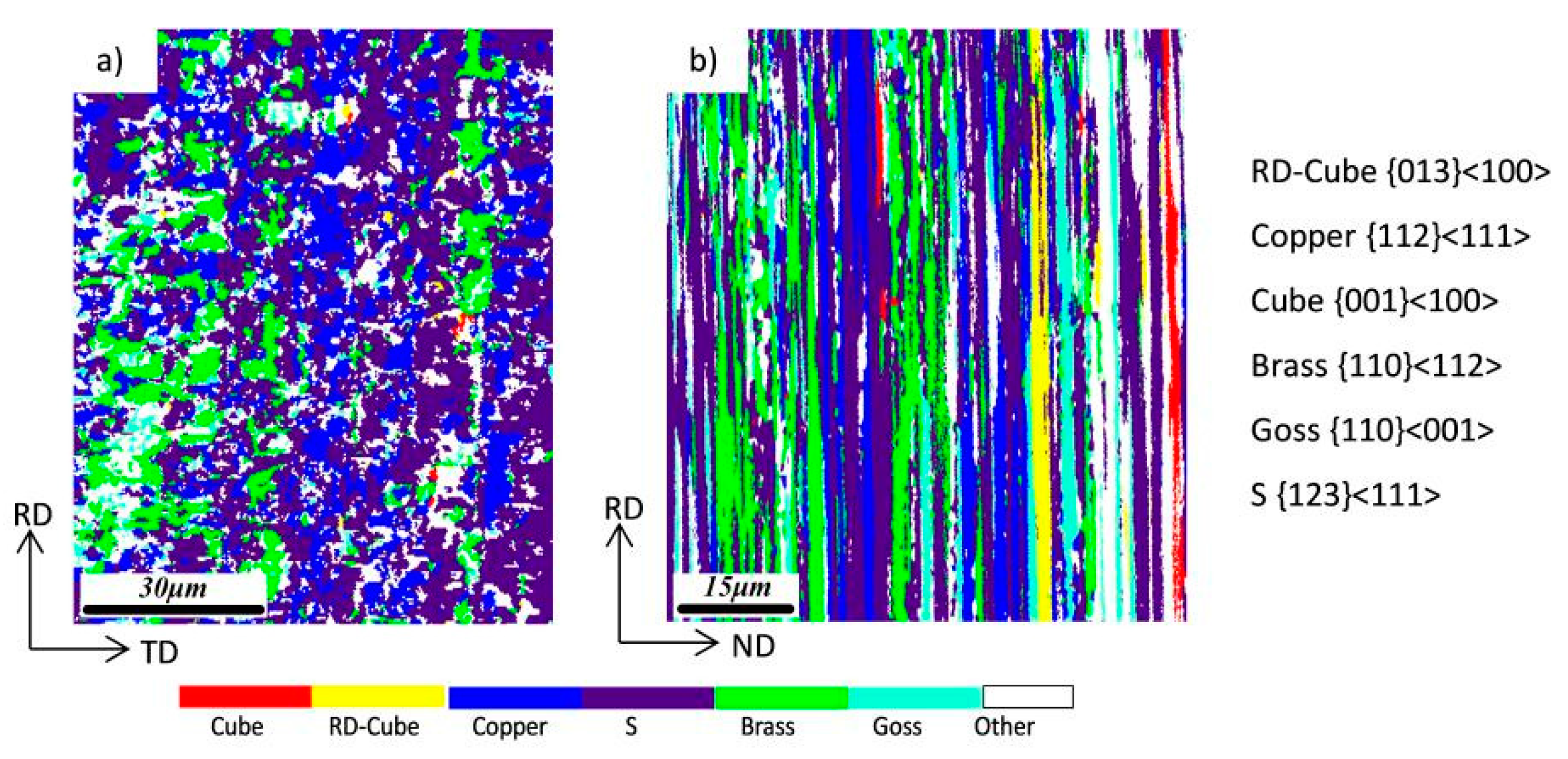
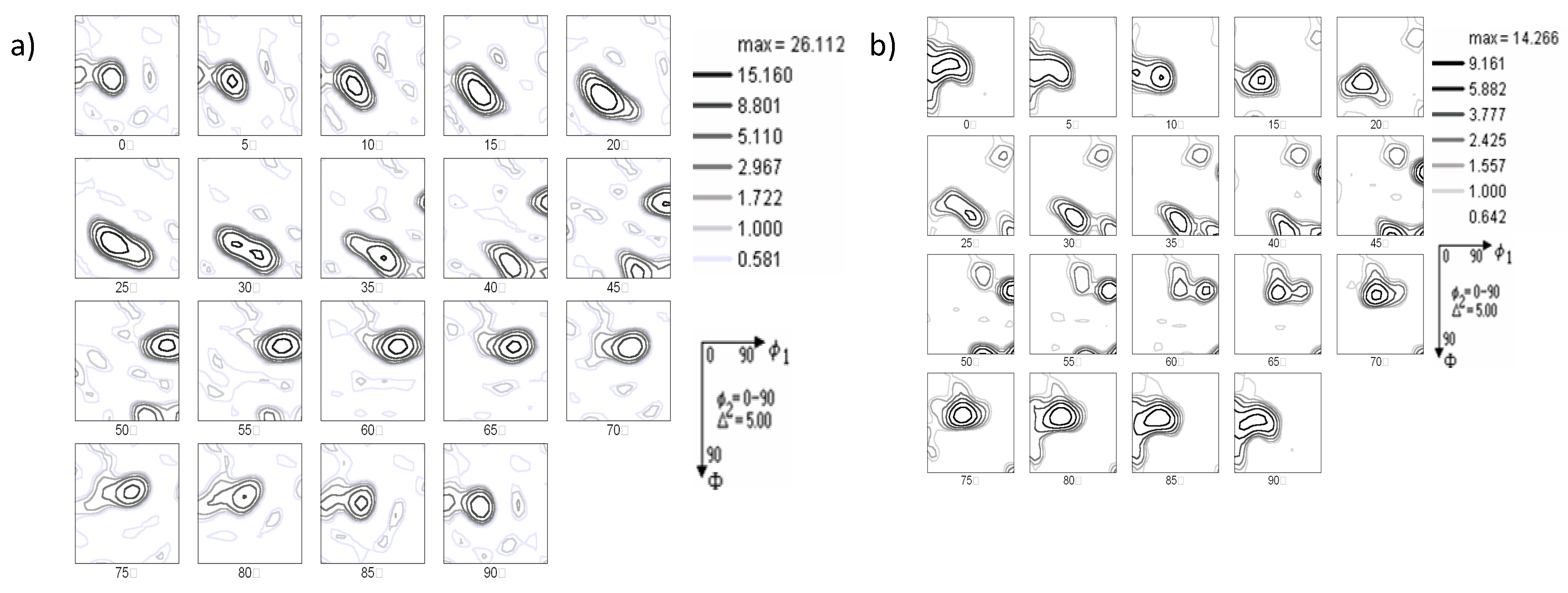
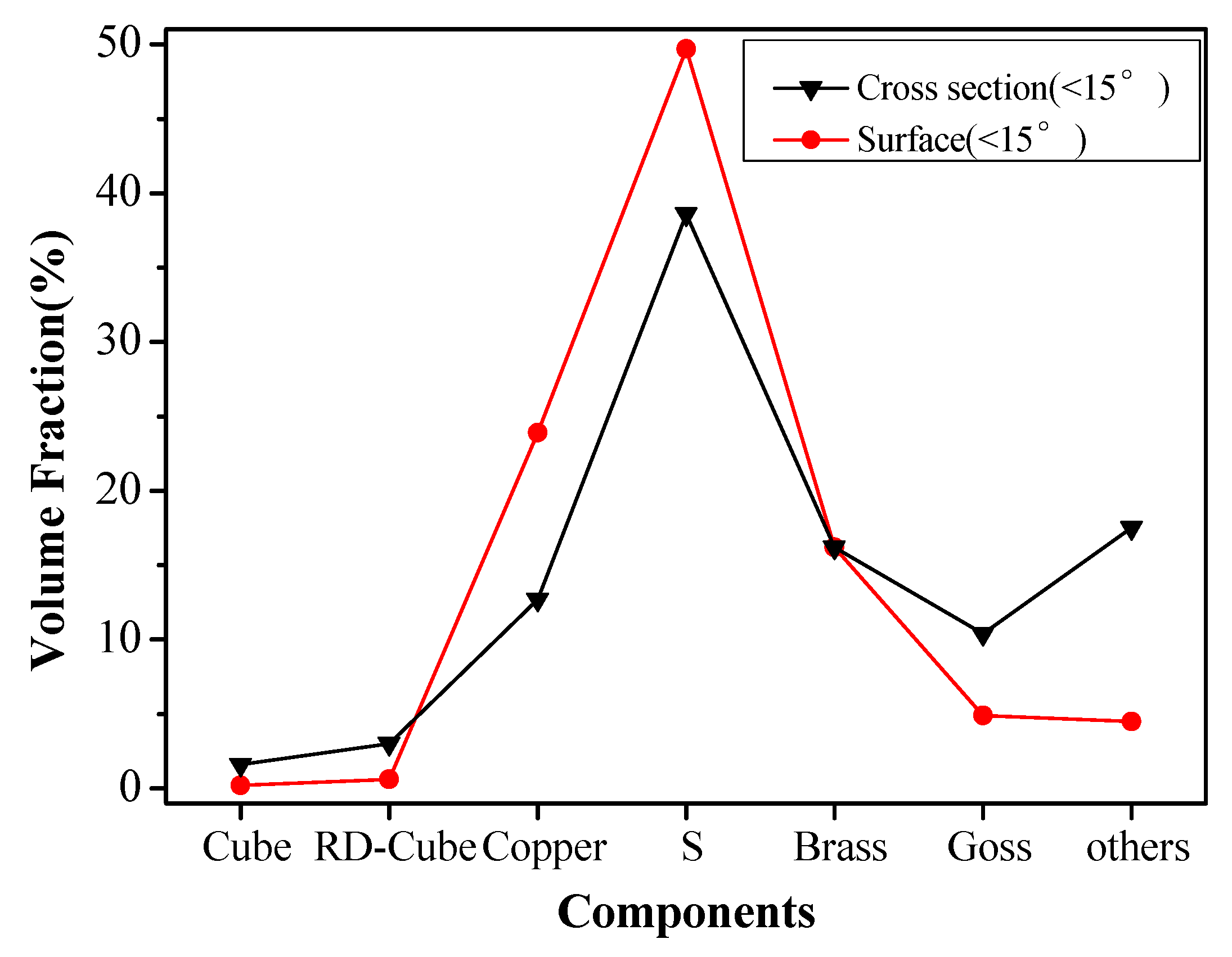
3.1. The Study on the Microstructure of Cold-Rolled Ni5W Alloy Substrate

The deformed structure of the Ni5W alloy substrate was analyzed and characterized via the EBSD technique, and the direction distribution patterns of RD-TD (defined as the surface) and RD-ND (defined as the cross-section) were measured in randomly selected areas, as shown in Figure 1a,b. The micro-deformation texture was dominated by copper, S and brass textures, indicating a typically high deformation texture of the face-centered-cubic (FCC) metal. A small volume fraction for cube and rotated cube textures was also observed to be consistent with the macroscopic textures obtained from the XRD pattern [16].
Comparing the distribution of deformation textures on the surface and cross-section, we can see that there is some difference in the distribution of micro-deformation between the surface and cross-section. Both the surface and cross-section show the strong brass, S and copper orientation deformation area. However, on the surface, a small amount of Goss, cube and RD-cube deformation texture exists besides the brass, S and copper orientation deformation tissues, which are different from the deformation tissues of the surface. This is mainly due to the different forces on the surface and the core layer. At the same time, the deformation structure of the cross-section surface is the long thin sheet, and the surface is subjected to a large stress, thus the work hardening phenomenon is obvious during the deformation process. Some dislocations slip in octahedral mode, resulting in an irregular distribution of deformation structure. It can also be seen from the orientation distribution of the cross-section surface that a small amount of cube deformation area exists near the S deformation area. According to the 40°-<111> growth relationship, this creates a powerful condition for the rapid growth of cube-oriented nuclei during recrystallization annealing [12].
To further analyze the microstructure distribution of the cold-rolled Ni5W alloy substrate, its ODF orientation distribution function is plotted in Figure 2. Figure 2a,b is ODFs of the cold-rolled Ni5W alloy substrate in the surface and cross-section. It can be seen from these figures that the deformation orientation of the surface is mainly copper and S orientation, and its intensity maximization is concentrated around the standard location. At the same time, there is a strong brass orientation near (Φ1, Φ, Φ2) = (35.3°, 45°, 90°). In addition, only a small amount of Goss orientation is present in the vicinity of (Φ1, Φ, Φ2) = (0°, 45°, 0°). The cold-rolled texture on the cross-section is dispersed from its standard position, while Copper and S orientations are also shifted from their standard positions, in which maximum intensities are not as high as on the surface. The brass orientation has a relatively large intensity value and a small amount of Goss orientation exists near the positions of (Φ1, Φ, Φ2) = (0°, 45°, 0°). However, the deformation texture generally shows copper orientation.
The variation of each orientation in the surface and cross-section is shown in Figure 3. The distribution of various textures on the surface and cross-section was different. The fraction of S and copper texture in the surface is obviously higher, while the fractions of brass, Goss, cube and RD-cube are lower, indicating that the deformation texture of the surface is a typical copper deformation texture rather than brass deformation texture according to the formula [17]. Compared to the surface, the S and cube orientations of the cross sections are lower, which is mainly caused by the uneven distribution of stress in the thickness of the whole substrate in the rolling process.

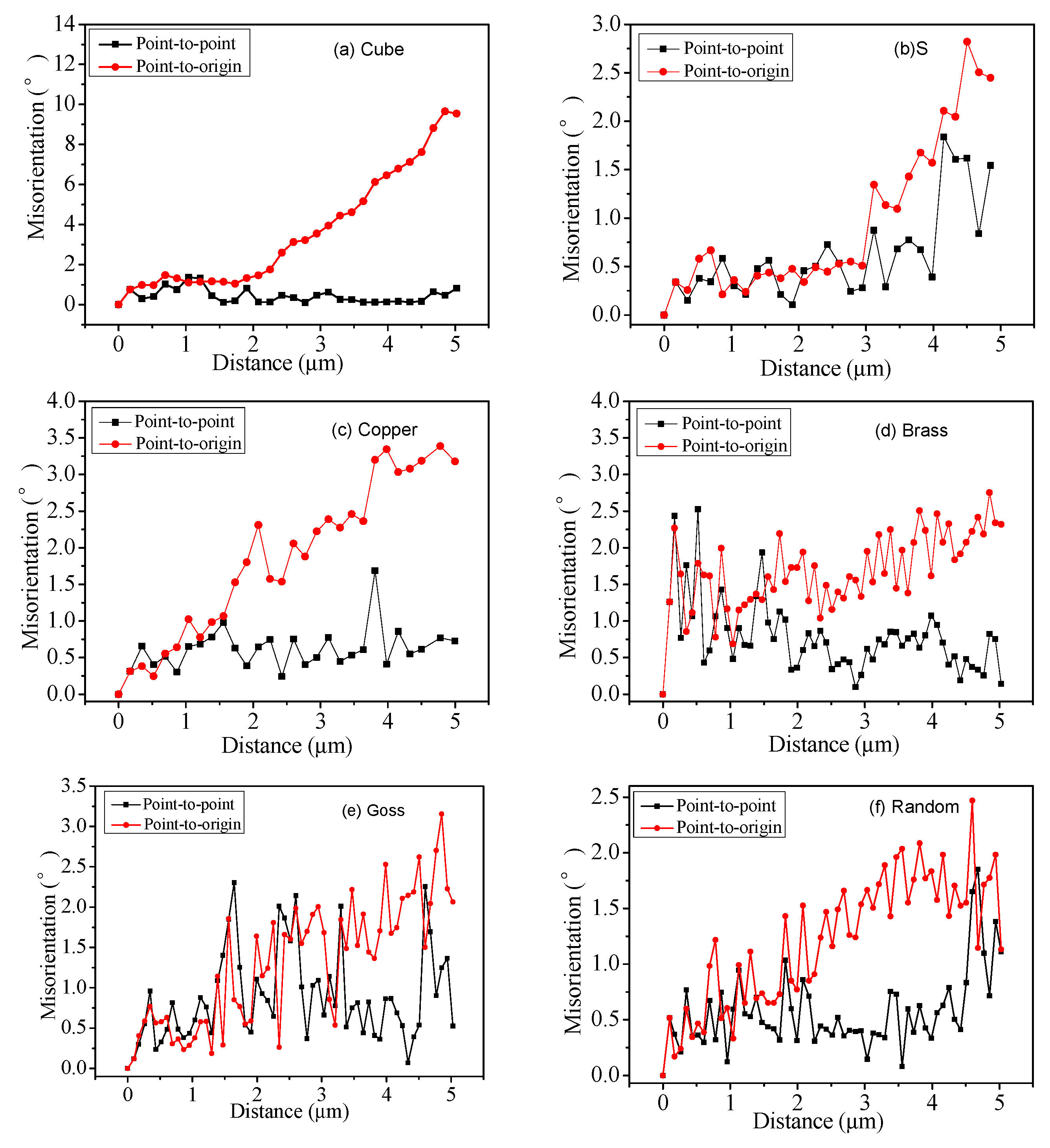
3.2. The Microstructure Orientation Gradient of Cold-Rolled Ni5W Alloy Substrate

It was found that there is a clear orientation gradient in the cube-oriented deformation area. Figure 4a–f shows the results of the line scan for different orientations in the substrate. The red curve represents the cumulative orientation difference from the nucleus to the initial point, and the black curve represents the point-to-point orientation difference distribution curve in the nucleus.
It can be seen from Table 1 that the cube-oriented deformation area has an obvious orientation gradient in the range of 5 μm, with the maximum value of the intra-crystal orientation difference reaching 12.1°. This indicates that the orientation is rotated, changing from cube to rotated-cube (RD-Cube) in a small distance. At the same time, the cube-oriented deformation area is surrounded by large-angle grain boundaries. In general, the higher grain boundary energy leads to more unstable grain boundaries and to a greater migration rate. There is a clear relationship between the grain boundary energy level and the adjacent crystal orientation. Generally, the energy of large-angle grain boundaries is higher than the small-angle grain boundaries or twin boundaries, thus the mobility of the large-angle boundaries is also high. Therefore, these large-angle grain boundaries can provide a larger growth rate for recrystallized nuclei during the subsequent recrystallization.
Compared with the cube-oriented deformation area, the orientation gradient in the non-cube deformation area is small and there is no obvious orientation gradient. Within the analysis range of the S deformation zone (about 5 μm), the maximum value of the difference in the intragranular orientation is only 2.8°. The maximum value of the copper deformation zone (about 4.5 μm) is 3.3°. The maximum value of the brass orientation zone (about 7 μm) is 3.7°. Within the analytical range of the Goss orientation zone (about 5.5 μm), the maximum value of the internal orientation difference is only 3.1°. The random orientation is within the analysis range of 5.5 μm and the maximum value of the intra-crystal orientation difference is only 2.4°. According to the literature [18], the high intragranular orientation gradient creates a strong condition for the nucleation during the later heat treatment. At the same time, the average intergranular spacing of the large-angle grain boundaries is about 0.57 μm and its volume fraction is 60.2%, which also provides a strong condition for recrystallized grain growing.
Based on the above analysis, the high orientation gradient in the cube-oriented deformation area creates a strong condition for the nucleation of cube-oriented nuclei, which are surrounded by large-angle grain boundaries and provide large growth due to their subsequent recrystallization driving force [19].

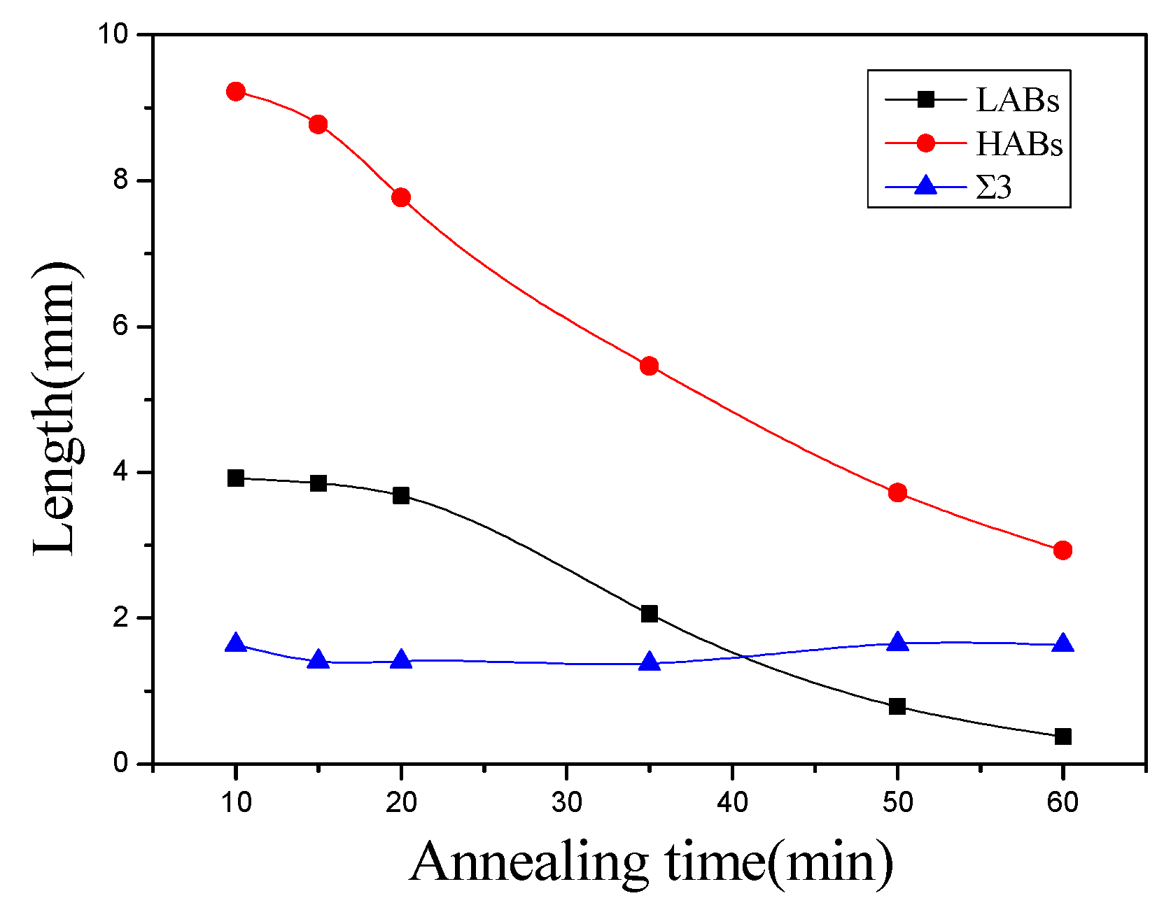
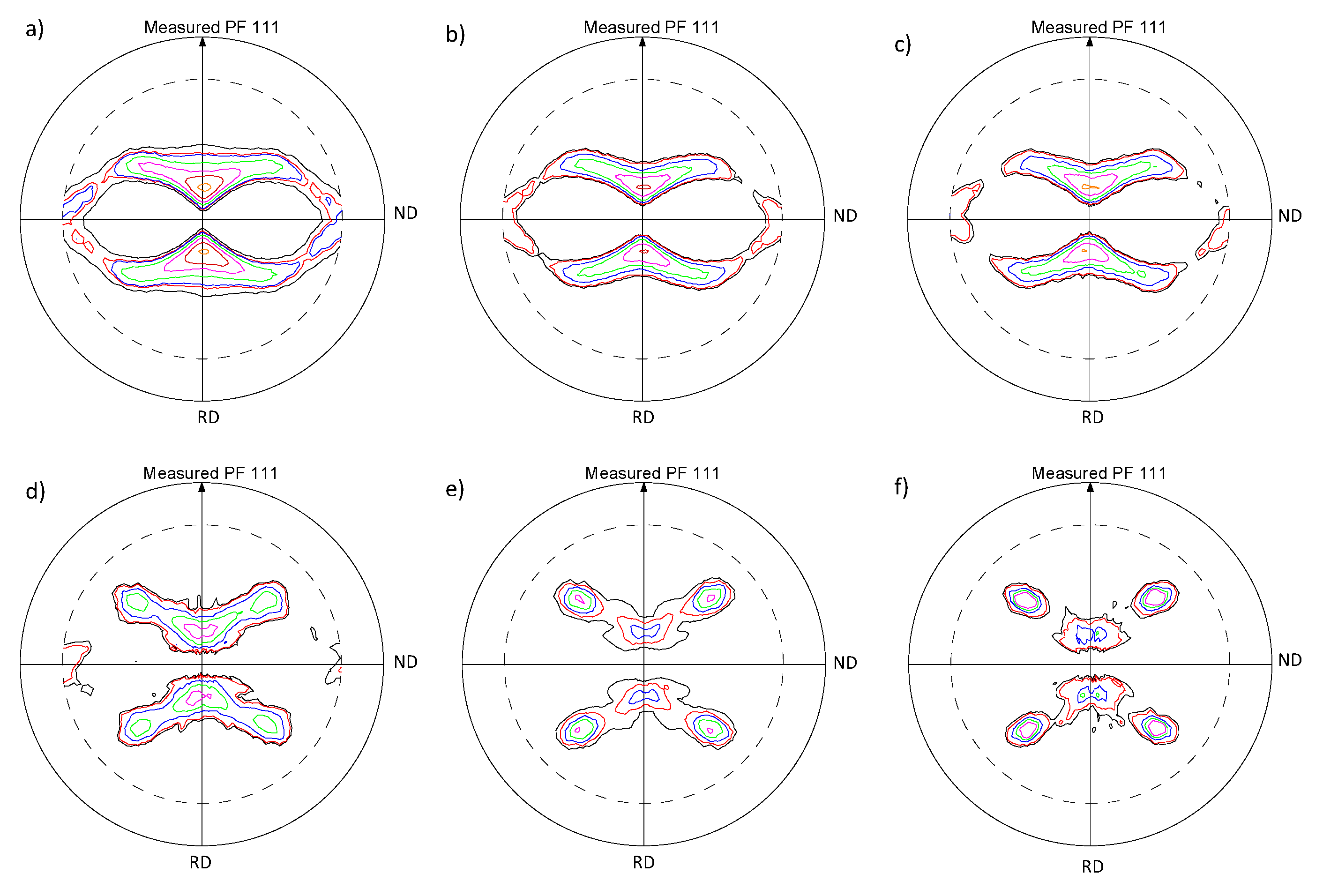
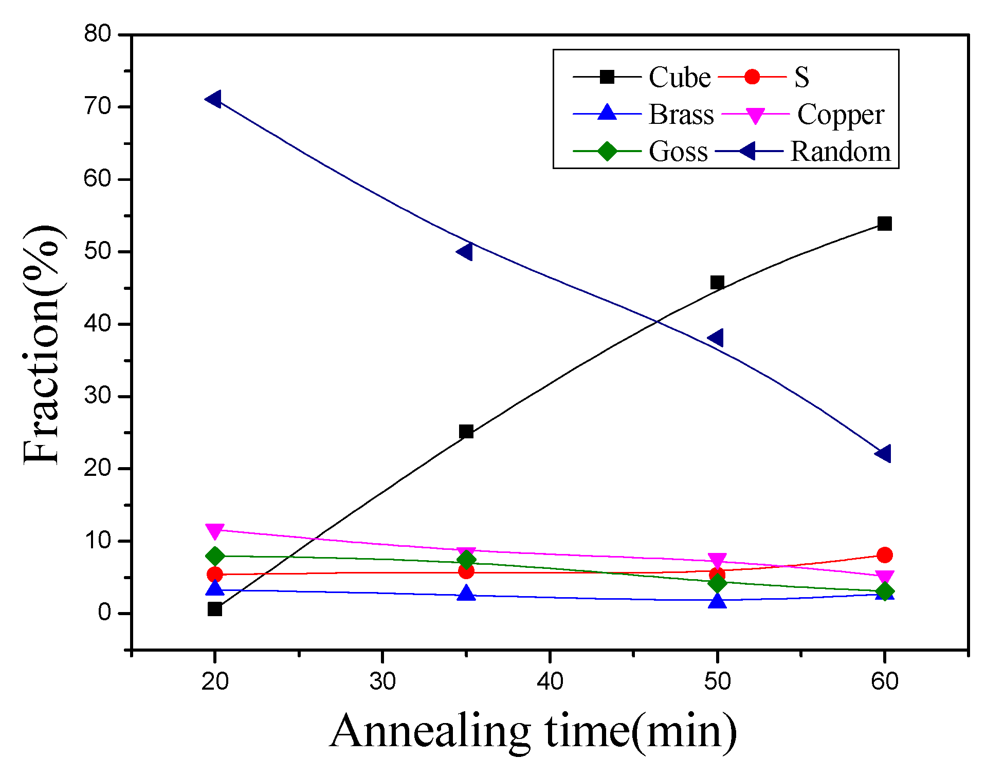
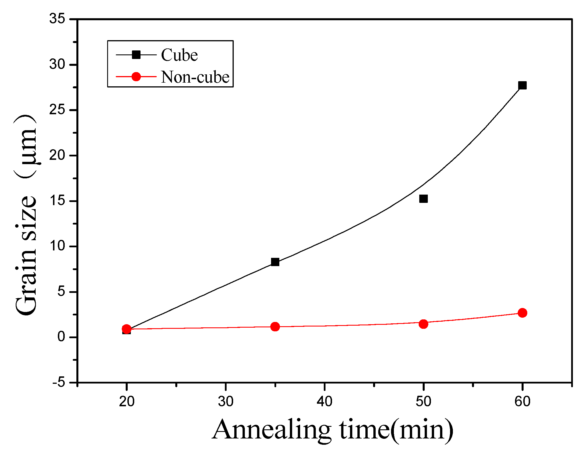
3.3. The Study on the Microstructure and Texture of Ni5W Alloy Substrate during Recrystallization

Quasi-in situ EBSD maps of Ni5W alloy substrate annealed at a temperature of 700 °C with different annealing times are shown in Figure 5. These four maps are from the same location of the sample and they have the same size. The presence of rolled structures and a few recrystallized nuclei indicates the starting of recrystallization at a temperature of 700 °C during the 20 min period. The long-shaped rolled structure was continuously coarsened due to the migration of grain boundaries and contributed towards the equiaxed recrystallized grains [20,21]. However, the cube orientation did not obtain any significant advantage in nucleation due to the presence of random and rolling orientations such as S, copper, and brass. The number of cube-oriented grains was increased while the number of random and rolling orientation grains was reduced significantly with the increase in heat treatment. The size of cube grains was also significantly changed as compared to other oriented grains due to rapid growth. During the heat treatment for 60 min, the cube grains were grown to such an extent that they occupied most of the area. Most of the rolling-oriented grains, especially the randomly oriented grains, were swollen by the cube-oriented grains.
During the recrystallization process, recrystallized grains form and grow continuously in the rolling microstructure through the migration of large-angle grain boundaries, thus the recrystallized microstructures include the recrystallized grains, as well as part of the rolling microstructures. The grains circled in the figure are the rolled oriented and random oriented grains, and the surrounding cube grains gradually move towards the center and swallow it when kept warm for 50 min. In this process, the misorientation between grains gradually decreases through the migration of grain boundaries and finally becomes a low angle grain boundary, tending to a stable state. This is because the grain boundary structure has a great influence on grain boundary migration [22]. When the rolled oriented grain is surrounded by cube crystal grain, the misorientation between them is larger, and the larger the misorientation between grains, the higher the interfacial energy, so the grain boundary structure is not stable. The grain boundary migration distance and migration rate increase correspondingly, and the surrounding cube grains begin to move rapidly to the middle to annex the rolled oriented grain. However, when two cube grains are adjacent to each other, the grain boundary between them changes into a low angle grain boundary. The grain boundary with a low angle or a special angle, such as a twin boundary, has a very low migration distance and migration rate and does not even move. Therefore, when the two cube grains are adjacent, the interface is relatively stable, and it is not easy to move.
Figure 6 shows the variation in the length of high-angle grain boundaries (HABs), low-angle grain boundaries (LABs) and Σ3 grain boundaries during recrystallization. It can be seen that the length of high-angle grain boundaries and low-angle grain boundaries is significantly decreased, among which the length of high-angle grain boundaries decreased by 2.93 mm, and the length of low-angle grain boundaries decreased by 0.37 mm, while the length of twin boundaries did not change significantly. This indicates that the fraction and size of the twins did not change obviously during the initial recrystallization, and the twin boundaries have high thermal stability. However, cube grains can encroach on rolling-oriented and randomly-oriented grains through the migration of large-angle grain boundaries, resulting in the size of cube grain increasing and the number of rolled and randomly oriented grains decreasing, thus the length of large-angle grain boundaries and low-angle grain boundaries decrease.
It can be seen from Figure 5 that during recrystallization, the texture of the Ni5W alloy substrate gradually changes from rolling texture at the initial stage of recrystallization to recrystallization texture with cube texture. Figure 7 shows the (111) pole figures of the recrystallization process of the Ni5W alloy substrate. It can be seen that the texture gradually changes from copper rolling texture to a mix of copper rolling texture and cube texture, and finally to a sharp cube texture. The transformation of texture type indicates that a strong cube texture will be formed after recrystallization, and the formation of recrystallized cube texture will rapidly swallow up the rolling texture and random texture.
The curve of the fraction of different recrystallized grains during heat treatment is shown in Figure 8. It can be seen that in the initial stage of recrystallization, the fraction of random oriented recrystallized nuclei is the highest, followed by S and Goss oriented recrystallized nuclei. However, the cube-oriented recrystallized nuclei is least, which means the nucleation rate of cube orientation is lower than other orientations, because the recrystallized nuclei are produced from the recrystallized microstructure and the shear microstructure in the rolling microstructure is beneficial to the formation of the recrystallized nucleus [23]. However, there are fewer cube orientations in the rolling and recovery microstructures of Ni5W alloy substrate. Most recrystallization nuclei are rolling and random orientation grains, so the cube orientation grains do not have an obvious quantitative advantage in nucleation. However, during the process of recrystallization, it is seen that the fraction of cube orientation increased by 53.2%, while the fraction of random orientation decreased rapidly by 49.1%, and the fraction of rolling orientations only reduced a little, which indicates that a large number of random orientations and a small amount of rolling orientations are consumed by cube orientation during recrystallization.
In the recrystallization process, not only the cubic orientation grains grow up gradually, but also the rolling orientations and random orientations grains grow up. Figure 9 shows the variation of average grain size of different recrystallized grains during heat treatment. It can be seen that the size of cubic grains increases rapidly in the middle and later stages of recrystallization, and the growth rate is much higher than that of other size grains, the cubic grains have an obvious size advantage [18]. Therefore, cubic grains will annex the non-cubic structure through the migration of large angle grain boundaries to form recrystallized cubic texture in this process, and after initial recrystallization, the content of cubic texture reached 53.9%.

4. Summary

The texture type of cold-rolled Ni5W alloy substrate is a typical copper deformation texture. Copper orientation and S orientation on the TD-RD surface of Ni5W alloy substrate are higher, reaching 21.4% and 43.5% respectively, while Copper orientation and S orientation on the ND-RD surface are 11.2% and 26.3%, respectively. The microstructures of cold-rolled Ni5W alloy substrate are long thin sheet structures with an average spacing of 0.57 μm. The cube-oriented deformation area has a clear orientation gradient, which creates strong conditions for its nucleation. The cube-oriented deformation area is surrounded by the large-angle grain boundaries and provides a larger growth driving force for its growth during subsequent recrystallization. In the recrystallization process, the average grain boundary spacing increases with the holding time, reaching 2.5 μm, and the grains gradually change from long thin sheets to equiaxed. The number of cube-oriented grains in the initial recrystallization is less, and they do not have the quantitative advantage, but their growth rate is higher than other oriented grains, and they have a significant size advantage. It can form the strong cube texture by swallowing up the random orientation and rolling orientation through the migration of large-angle grain boundaries.

Author Contributions

Conceptualization, H.S., L.M. and M.L.; methodology, C.Z.; software, Y.W. and J.L.; validation, Q.W.; formal analysis, C.Z. and Z.Z.; investigation, H.S.; data curation, Y.J.; resources, H.S.; writing—original draft preparation, C.Z.; writing—review and editing, C.Z. and Z.Z.; visualization, C.Z.; supervision, H.S. and Z.Z.; project administration, H.S.; funding acquisition, H.S.

Funding

This research was funded by the National Natural Science Foundation of China (51571002, 51702316, 51307163, 11745005 and 51477167), by the General Program of Science and Technology Development Project of Beijing Municipal Education Commission of China (KM201810005010), by the Beijing Municipal Natural Science Foundation (2172008), by the Evaluation Research for the Performance of MgB2 Tapes (GH-201809CG005) and by 211 Program of Beijing City and Beijing University of Technology. National Natural Science Foundation of China (51777205 and 11745005), Beijing Science and Technology Project (Z181100003818020), International Partnership Program of Chinese Academy of Sciences (182111KYSB20170067). YD was supported by International Partnership Program of Chinese Academy of Sciences (182111KYSB20170039). JC was supported by Major Scientific Instrument Development Project of Natural Science Foundation of China (51827810).

Conflicts of Interest

We declare that we have no financial and personal relationships with other people or organizations that can inappropriately influence our work, there is no professional or other personal interest of any nature or kind in any product, service and/or company that could be construed as influencing the position presented in, or the review of, the manuscript entitled.

References

  1. Baecher, M.; Feenstra, R.; Wojtyniak, B.; Falte, M.; Bennewitz, J.; Kunert, J.; Rikel, M.O. Production and characterization of YBCO superconductor tapes produced by chemical solution deposition processes. In Proceedings of the Applied Superconductivity Conference, Denver, CO, USA, 4–9 September 2016. [Google Scholar]
  2. Walsh, R.P.; McRae, D.; Markiewicz, W.D.; Lu, J.; Toplosky, V.J. The 77-K Stress and Strain Dependence of the Critical Current of YBCO Coated Conductors and Lap Joints. IEEE Trans. Appl. Supercond. 2012, 22, 8400406. [Google Scholar] [CrossRef]
  3. Nakasaki, R.; Brownsey, P.; Sundaram, A.; Zhang, Y.; Hazelton, D.; Sakamoto, H.; Fukushima, T. Progress of 2G HTS wire development at SuperPower. In Proceedings of the Applied Superconductivity Conference, Denver, CO, USA, 4–9 September 2016. [Google Scholar]
  4. Norton, D.P.; Goyal, A.; Budai, J.D.; Christen, D.K.; Kroeger, D.M.; Specht, E.D.; He, Q.; Saffian, B.; Paranthaman, M.; Klabunde, C.E.; et al. Epitaxial YBCO on biaxially textured nickel (001): An approach to superconducting tapes with high critical current density. Science 1996, 274, 755. [Google Scholar] [CrossRef]
  5. Rupich, M.W.; Li, X.; Thieme, C.; Sathyamurth, S.; Fleshler, S.; Tucker, D.; Thompson, E.; Schreiber, J.; Lync, J.; Buczek, D. Advances in second generation high temperature superconducting wire manufacturing and R&D at American Superconductor Corporation. Supercond. Sci. Tech. 2010, 23, 014–015. [Google Scholar]
  6. Goyal, A.; Ren, S.X.; Specht, E.D.; Kroeger, D.M.; Feenstra, R.; Norton, D.; Paranthaman, M.; Lee, D.F.; Christen, D.K. Texture formation and grain boundary networks in rolling assisted biaxially textured substrates and in epitaxial YBCO films on such substrates. Micron 1999, 30, 463–478. [Google Scholar] [CrossRef]
  7. Hughes, D.A.; Hansen, N. Microstructural evolution in nickel during rolling from intermediate to large strains. Metall. Mater. Trans. A 1993, 24, 2022–2037. [Google Scholar] [CrossRef]
  8. Tian, H.; Zhang, Y.; Mishin, O.; Suo, H.L.; Grivel, J.C. Nanostructured Cu-45 at.% Ni alloy produced by heavy cold rolling. In Proceedings of the 33rd Risø International Symposium on Materials Science, Roskilde, Denmark, 3–7 September 2012; pp. 349–354. [Google Scholar]
  9. Li, X.L.; Liu, W.; Godfrey, A.; Jensen, D.J.; Liu, Q. Development of the cube texture at low annealing temperatures in highly rolled pure nickel. Acta Mater. 2007, 55, 3531–3540. [Google Scholar] [CrossRef]
  10. Hui, T.; Suo, H.; Qiu, H.; Liu, M.; Ma, L.; Wang, L.; Yuan, D.; Wang, Y. Investigation of Cold Rolling Texture and Recrystallization Texture in NiW Substrates. Rare Met. Mater. Eng. 2011, 40, 329–333. [Google Scholar]
  11. Lee, K.H.; Yoo, J.; Ko, J.; Kim, H.; Chung, H.; Chang, D.; Lee, J.Y. Fabrication of biaxially textured Ni tape for YBCO coated conductor by electrodeposition. Physica 2002, 372, 866–868. [Google Scholar] [CrossRef]
  12. Bhattacharjee, P.P.; Ray, R.K.; Tsuji, N. Cold rolling and recrystallization textures of a Ni-5at.% W alloy. Acta Mater. 2009, 57, 2166–2179. [Google Scholar] [CrossRef]
  13. Wright, S.I.; Nowell, M.M.; de Kloe, R.; Camus, P.; Rampton, T. Electron imaging with an EBSD detector. Ultramicroscopy 2015, 148, 132–145. [Google Scholar] [CrossRef] [PubMed]
  14. Wilkinson, A.J.; Britton, T.B. Strains, planes, and EBSD in materials science. Mater. Today 2012, 15, 366–376. [Google Scholar] [CrossRef]
  15. Wright, S.I.; Nowell, M.M.; Lindeman, S.P.; Camus, P.P.; De Graef, M.; Jackson, M.A. Introduction and comparison of new EBSD post-processing methodologies. Ultramicroscopy 2015, 159, 81–94. [Google Scholar] [CrossRef] [PubMed]
  16. Yoo, J.; Kim, Y.K.; Ko, J.; Lee, K.H.; Chung, K.; Chung, H. Formation of strongly biaxial-textured Ni Layer for YBCO coated conductor by electrodeposition process. IEEE Trans. Appl. Supercond. 2005, 15, 2624–2627. [Google Scholar] [CrossRef]
  17. Shi, K.; Feng, F.; Wu, W.; Wang, Z.; Han, Z. Recent process in coated conductor by IBAD method and the preparation of long YSZ/Hastelloy C-276 Substrates. Chin. J. Low Temp. Phys. 2010, 32, 116–120. [Google Scholar]
  18. Hartley, P.; Sturgess, C.E.N.; Liu, C.; Rowe, G.W. Experimental and theoretical studies of workpiece deformation, stress, and strain during flat rolling. Metall. Rev. 1989, 34, 19–34. [Google Scholar] [CrossRef]
  19. Zeng, Z.R.; Zhu, Y.M.; Xu, S.W.; Bian, M.Z.; Davies, C.H.J.; Birbilis, N.; Nie, J.F. Texture evolution during static recrystallization of cold-rolled magnesium alloys. Acta Mater. 2016, 105, 479–494. [Google Scholar] [CrossRef]
  20. Zhao, B.; Verhasselt, J.C.; Shvindlerman, L.S.; Gottstein, G. Measurement of grain boundary triple line energy in copper. Acta Mater. 2010, 58, 5646–5653. [Google Scholar] [CrossRef]
  21. Doherty, R.D. The deformed state and nucleation of recrystallization. Met. Sci. 1974, 8, 132–142. [Google Scholar] [CrossRef]
  22. Galina, A.V.; Fradkov, V.Y.; Schvindlerman, L.S. Influence of grain ternary joint mobility on boundary migration. Fiz. Met. Metalloved. 1987, 63, 1220–1222. [Google Scholar]
  23. Cahn, R.W. A new theory of recrystallization nuclei. Proc. Phys. Soc. 2002, 63, 323–336. [Google Scholar] [CrossRef]
Figure 1. Orientation distribution mapping of cold-rolled Ni5W substrate: (a) RD-TD (surface), (b) RD-ND (cross-section).
Crystals 09 00604 g001
Figure 2. ODF sections of cold-rolled Ni5W alloy substrates: (a) RD-TD, (b) RD-ND.
Crystals 09 00604 g002
Figure 3. Texture distribution of cold-rolled Ni5W substrates.
Crystals 09 00604 g003
Figure 4. Orientation distribution map and line scan misorientation of the cold rolling Ni5W substrates: (af) the point-to-point and accumulated misorientation vs. distance plots of a cube, S, copper, brass, Goss and random.
Crystals 09 00604 g004
Figure 5. EBSD maps of recrystallization in the Ni5W alloy substrate annealed at 700 °C with different annealing times: (a) 20 min, (b) 35 min, (c) 50 min, (d) 60 min.
Crystals 09 00604 g005
Figure 6. Length of HABs, LABS and Σ3 boundaries of the Ni5W alloy substrate during recrystallization.
Crystals 09 00604 g006
Figure 7. (111) pole figures of recrystallization in the Ni5W alloy substrate annealed at 700 °C with different annealing time: (a) 10 min, (b) 15 min, (c) 20 min, (d) 35 min, (e) 50 min, (f) 60 min.
Crystals 09 00604 g007
Figure 8. The fraction of different orientations of the Ni5W alloy substrate annealed at 700 °C.
Crystals 09 00604 g008
Figure 9. The average grain size of different recrystallized grains for the Ni5W alloy substrate annealed at 700 °C.
Crystals 09 00604 g009
Table 1. Misorientations of the rolling band in cold-rolled tapes.
OrientationPoint to Origin (°)
S2.8
Copper3.3
Brass3.7
Goss3.1
non-Cube2.4
Cube12.1

