


Abstract
The aim of this work was to explore and test the concept of a novel direct nucleation control method with external dissolution of fine crystals (E-DNC). It was postulated that the heating cycles of the internal DNC method could be transferred from the crystallizer jacket to an electrically heated recirculation tube, thereby using less energy and requiring a shorter time compared to internal DNC. The conceptual model was explored and developed by reviewing previous research on the topic and addressing known drawbacks. Engineering experience and a heuristic approach led to the conclusion that five commonly used controllers would suffice for a straightforward implementation of the method. A simplified simulation was developed to compare the time and energy requirements for the internal and external DNC methods, and it was concluded that external DNC uses 37% less energy and 19% less time compared to internal DNC. The laboratory system was then constructed by modifying the internal DNC apparatus with inexpensive and commonly used components. A linear cooling experiment was performed to establish the baseline for comparison with E-DNC experiments and to set the expected count range. The E-DNC experiments were then conducted with the aim of obtaining larger crystal sizes, and it was shown that the process could be designed in only three experiments. Adjusting the heating rate and count limit led to a significant increase in median crystal size (22.5%) compared to linear cooling.
1. Introduction
The pharmaceutical and fine chemical industries produce products with high added value, making them highly profitable and important for modern economies [1,2]. Manufacturing active pharmaceutical ingredients (APIs), particularly small molecules, requires the purification and isolation of intermediates and final products. These steps are typically carried out by some form of crystallization, such as batch cooling or antisolvent crystallization. Research equipment for common crystallization methods has been perfected by well-established companies and has become the informal industry standard. This has reduced research costs and enabled partial automation; however, manufacturers have remained largely indifferent to recent developments in the field, resulting in an instrumentation gap that hinders the transfer of new findings into applied research.
In industry, batch crystallizers are rarely separate pieces of equipment; more often, they are the same reactors in which the final synthesis step is carried out. Temperature control is usually achieved by heat transfer through the jacket using heating and cooling media. The heating and cooling system can be designed in several ways, depending on the reactor scale. For example, large reactors use steam for heating and a cold medium for cooling; however, these rarely pass through the same path, as switching between the two can cause high stress on the equipment. Therefore, another heat transfer fluid is introduced to serve as a buffer, exchanging heat with the cooling medium and steam via separate heat exchangers, thereby reducing stress on the equipment. Another approach, similar to that used in research laboratories, employs thermal circulators with silicone oil as the heat transfer medium. The medium is heated with an electric heater and cooled with a refrigeration system, making it compact and localized. This approach is simple but can be difficult to apply to a large crystallizer. However, such systems are easy to operate, share many similarities, and are becoming more common for challenging crystallization processes.
2. Theoretical Section
Crystal size represents a critical quality attribute that is strongly dependent on the intended application. In pharmaceutical manufacturing, particles within the approximate range of 100–300 µm are generally preferred, as they provide an optimal balance between filtration efficiency, flow properties, and dissolution performance [3]. Crystals of smaller size (below 50 µm) are often associated with reduced filtration rates, increased solvent retention, and handling challenges [4]. In contrast, excessively large crystals (above 500 µm or approaching the millimeter scale) may exhibit slower dissolution kinetics and variability in bioavailability [5].
A large majority of pharmaceuticals and fine chemicals are manufactured in batch reactors, even though new technologies such as continuous crystallization are becoming increasingly popular [6]. There are three distinct states that occur during batch cooling crystallization: undersaturation, saturation, and supersaturation. When the solution is in a supersaturated state, new crystals can form by primary nucleation or be added as seeds. Regardless of the choice, crystallization is typically operated in a growth-dominated region to avoid further nucleation. However, unwanted effects such as secondary nucleation can increase the number of small crystals and reduce the processability of the final product [3]. A common strategy in recipe design is to avoid high supersaturation to suppress secondary nucleation, typically achieved by slowly cooling the solution [1] or through supersaturation control [7]. However, impurities in the starting material can shift the solubility curve and alter the nucleation kinetics, rendering the recipe ineffective [8]. Additionally, slow cooling is undesirable from an economic perspective, as it results in lower turnover.
2.1. Direct Nucleation Control (DNC)
The philosophy of DNC is not to avoid secondary nucleation but to control it by dissolving unwanted small crystals [9]. It relies on process analytical technology (PAT) instruments such as FBRM (focused beam reflectance measurement) and process microscopy [10]. FBRM measures relative chord length distribution (CLD), while process microscopy calculates image-derived CLD, or the number of crystals appearing at the probe in a given time [11,12]. The method is usually implemented by in situ analysis of a slurry close to the probe, integrating CLD to obtain counts (total number of chord lengths) and maintaining this within acceptable boundaries by switching between cooling and heating until the final temperature is reached [13]. The counts serve as a proxy variable for the total number of crystals in the system, which is impossible to measure directly.
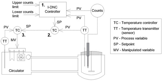
There is also a simpler alternative to DNC called temperature cycling [14,15], where a fixed number of heating cycles is used to achieve similar objectives without requiring PAT. DNC can be used for both unseeded and seeded crystallization [16], and there are various approaches to controlling temperature with respect to counts. Four different DNC algorithms exist for cooling crystallization: simple, basic, predictive, and reverse. Detailed descriptions of these algorithms are available in the literature [17]. It has been shown that basic DNC provides stable operation and better results than other algorithms; therefore, in our previous work, it was further simplified by reducing the number of heating and cooling rates from four to two [18]. The simplified basic DNC algorithm was used in this study for both system architectures. The system where heating and cooling are performed over the crystallizer jacket will be referred to as internal DNC (I-DNC). One way to construct an I-DNC system in the laboratory is presented in Figure 1, and a detailed example of systems engineering can also be found in our previous work [18].
Figure 1.
Schematic of a laboratory I-DNC system.
The circulator cools or heats the silicone oil, which exchanges heat with the crystallizer via the jacket. Three controllers control the system. The first is the DNC controller, a higher-level controller responsible for tracking the number of counts in the system and selecting either heating or cooling mode. The two temperature controllers (second and third in the figure) are cascade PID controllers. However, these are not standard PID controllers but a modified variant using a proprietary algorithm developed by the circulator manufacturer. This is because the standard PID cascade is insufficient for this type of control and would perform differently depending on the temperature setpoint (ramp, step change, or disturbance rejection) [19].
In addition to gains in average crystal size and improvements in morphology [8], DNC has demonstrated other significant potential. Several in-silico studies have investigated DNC or temperature cycling for various types of preferential crystallization [20,21,22]. It has been used experimentally for crystallization-induced deracemization [23], crystallization of biopharmaceutical compounds [24], selective dissolution of undesired polymorphs [25], polymer-induced crystal shape modification [26], and combined wet-milling temperature cycling [27].
2.2. DNC with External Heating Loop (E-DNC)
The main problem limiting the use of DNC in industrial crystallizers is the long time required to reheat the crystallizer and the associated economic implications, which increase the operating cost of the process [28]. In addition, more energy is consumed compared to cooling-only crystallization, depending on the number of heating cycles. A potential solution to this problem is to offload heating to a separate piece of equipment. The simulation study by Szilagyi [29] explored the use of external heat exchangers for the heating phase. However, this equipment configuration is uncommon in industry and could encounter several problems. Kacker [30,31] used both an external microwave oven and direct introduction of microwaves. This approach has shown promising results, reducing the required energy and batch time. Microwave heating offers benefits, but scale-up and implementation are difficult due to the non-uniformity of the field and concerns regarding ATEX-GMP compliance [32]. All previous studies share the fact that the cooling system remained operational while the heating system was active, creating a thermal short circuit in the system that caused unnecessary energy loss and prolonged the desired temperature change. Therefore, a solution to this problem, along with other improvements, is presented in subsequent sections.
3. Conceptual Model
In our proposed implementation, several innovative advantages are highlighted in both equipment design and process control strategy. The external heating loop can be constructed using a peristaltic pump, silicone tubing, and an electric tube heater. This approach offers the benefit that the pump does not contact the fluid, and the peristaltic pump can easily reverse direction to return any remaining slurry in the pipe to the crystallizer when the heating cycle is complete. Additionally, using an electric tube heater instead of a heat exchanger eliminates one process stream from the overall system, and the amount of heat transferred can be precisely controlled by adjusting the heater’s power. There are also fewer design constraints compared to heat exchangers, which are typically designed for a narrow temperature and operational range—conditions that are uncommon in batch crystallization systems. Furthermore, electric heaters are consistent with the broader trend towards electrification in the pharmaceutical industry and contribute to reducing waste and carbon footprint [32]. We also propose adding three check valves to physically isolate the heating and cooling systems, thereby preventing thermal short-circuiting and energy losses. These features align well with the time and energy domains of process intensification principles [33].
3.1. System Structure
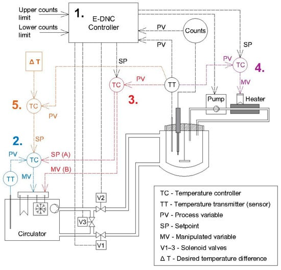
The process control structure includes several PLC-compatible controllers that can be easily integrated with legacy cascade temperature controllers in thermal circulators. This is important because the control system does not rely on a PC and can be managed by a PLC in both cases. The proposed system structure is shown in Figure 2, and this modified version of external DNC will be referred to as E-DNC.
Figure 2.
DNC system with external heating loop (E-DNC): Case A, cascade temperature control; Case B, direct temperature control.
It should be noted that the system structure has two distinct implementations, differing in the third controller. If proprietary commercial circulator controllers are used, the third controller acts as a master cascade controller for the second controller (Case A). Otherwise, the third controller controls reactor temperature by directly manipulating the heating and cooling power of the circulator (Case B).
3.2. Working Modes
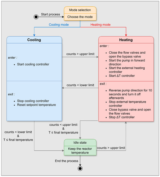
In the E-DNC system, two additional controllers are introduced. Controller 4 is a PID controller that controls the power of the electrical pipe heater, while controller 5 is a Delta T controller. The E-DNC controller is a state machine-type controller that acts as the master controller, responsible for switching the subordinate controllers on and off. The structure of the E-DNC controller is shown in Figure 3.
Figure 3.
E-DNC state machine controller structure.
When the system is in the cooling phase, valves one and two are open, while bypass valve three is closed. This allows the refrigerated oil to exchange heat with the crystallizer via the jacket. Conversely, when the system switches to heating mode, valves one and two are closed, and bypass valve three is opened, preventing the circulator oil from reaching the crystallizer jacket. The DNC controller sends a linear heating ramp setpoint to the electric heater controller (number 4) and activates the peristaltic pump. As the suspension is pumped through electrically heated tubes, its temperature increases, and it is returned to the crystallizer. Heating of the crystallizer is solely the responsibility of the external electric pipe heater. However, the oil in the circulator is also heated, and its temperature setpoint is determined by the Delta T controller, which sends the setpoint to a subordinate cascade temperature controller. The purpose of this arrangement is to have the circulator oil ready to start cooling the crystallizer when the system switches to cooling mode. It is necessary to keep the temperature of the oil slightly lower than that of the crystallizer; therefore, the controller is named the Delta T controller.
4. Simulation Model
4.1. Model Structure and Framework
Accurate modeling of the proposed system would require general mass and energy balances, crystal population balances, and CFD analysis. Such a simulation would require advanced skills and many parameters to be estimated, and therefore, important microphenomena occurring in the system could easily be overlooked [34]. The authors are of the opinion that such a simulation would be difficult to perform and could yield misleading results. However, a simpler simulation can be conducted to validate the concept and study potential energy savings and process duration reduction.
A simplified simulation considers the energy balance for pure water in the reactor, with crystallization modeled as an asymmetric linear increase in counts during cooling and a decrease during heating. The external heating loop is not modeled as a plug flow reactor (PFR) but is simplified by directly applying heating power, as if the heater were immersed in the reactor. This assumption is made for practical reasons: to avoid introducing spatial variation into the model and to avoid using the multiple tanks-in-series approximation of a plug-flow reactor [29]. This model is sufficient to test the control system and the main hypotheses regarding process intensification.
Process parameters for simulation are measured from the physical properties of our laboratory equipment and estimated based on experience. Assumptions about unmeasurable parameters (e.g., heat transfer coefficients) are made using best intentions and engineering judgment. The following mass and energy balances are used to describe the system in different operating modes:
Heating mode:
Cooling and idle mode:
For the I-DNC simulation, only the cooling (and idle) mode equations are used, and the system structure is the same as in Figure 1. Crystallization is simulated as follows:
The initial number of crystals (counts) is set at 1000, and the counts are increased or decreased proportionally to the rate of change of reactor temperature, multiplied by a weight factor. Different weight factors are assigned depending on the state of the DNC controller. In heating mode, the weight factor is larger than in cooling mode to reflect the realistic behavior of crystallization; in the idle state, there is no change in counts. This approach avoids classical crystallization modelling but yields similar results for concept testing purposes. The list of parameters and variables used in the simulation can be found in Table 1.
Table 1.
Variables and parameters for simulation.
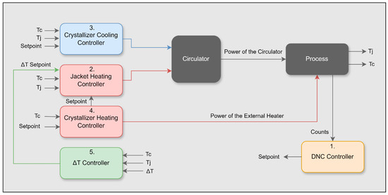
The model was developed in Simulink using mass and energy balances (s function) along with various process controllers. The controller number annotation corresponds to scenario (B) in the schematics in Figure 2, and the list of corresponding Simulink controllers is provided in Table 2. The general simulation structure is shown in Figure 4.
Table 2.
List of Simulink controller types and objectives.
Figure 4.
Simplified relationship among process simulation components.
4.2. Energy Consumption
The laboratory system uses only electricity as its energy source; therefore, the simulation records electrical energy consumption in kWh. In cooling mode, electrical energy is used by the cooling subunit within the thermal circulator, and the coefficient of performance (COP) is assumed to be 1 for the selected temperature range. In heating mode, energy is consumed by both the internal electrical heater within the circulator and the external electrical heater. The maximum cooling and heating powers of the thermal circulator are 1 kW and 2 kW, respectively, while the external electrical heater has a maximum power rating of 100 W. Overhead energy for the circulator pump, fans, and electronics is not considered; the focus is solely on energy differences between the internal and external DNC.
4.3. Simulation Scenarios
The simulation uses a cooling and heating rate of 0.25 °C/min, with the temperature decreasing from 40 °C to 10 °C. The count weight factors and the upper and lower count limits are selected to produce five heating cycles. In the E-DNC configuration, the temperature difference (ΔT) between the oil and the reactor is set to 3 °C in heating mode. The simulation terminates once a stable final temperature is reached. The total energy consumption is then calculated and used as the basis for comparing the I-DNC and E-DNC approaches.
5. Experimental Section
5.1. System Construction
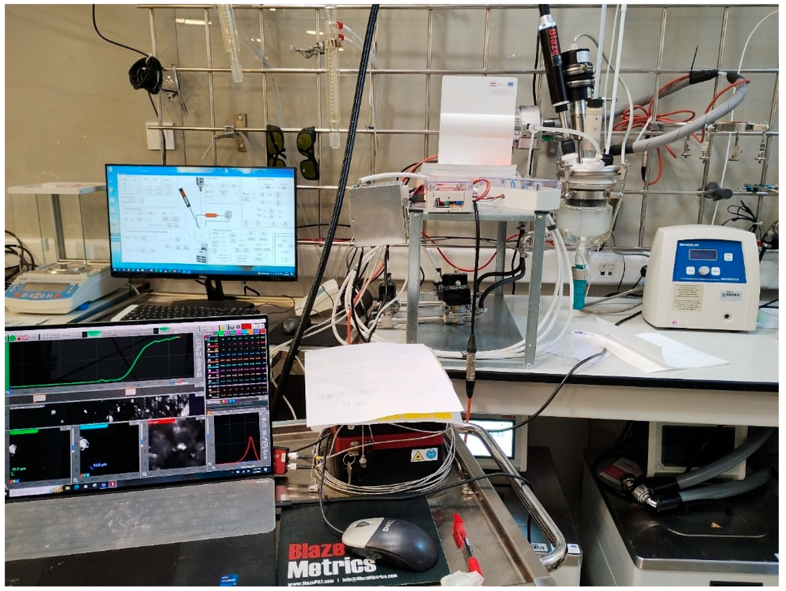
The system was constructed by modifying the I-DNC system described in our previous work [18]. A jacketed borosilicate glass batch reactor (500 mL, 100 mm diameter, HWS Labortechnik, Mainz, Germany) was fitted with an in-house 3D-printed turbine impeller (ABS filament, 60 mm diameter, six vertical blades). New equipment was introduced, namely a carbon-fiber electric tube heater (C-CORE 100W, Alconbury Weston Ltd., Stoke-on-Trent, United Kingdom), a Teflon tube (4 mm internal diameter, 0.5 mm wall thickness, Deutsch & Neumann GmbH, Berlin, Germany), a peristaltic pump (Rotarus flow 50, Hirschmann Laborgeräte GmbH & Co. KG, Eberstadt, Germany), solenoid valves (12 V, normally closed, 3/8″, 304 steel, AliExpress, Hangzhou, China), and pipes and fittings (3/8 in, 304 steel, AliExpress, Hangzhou, China). The heater controller was built in-house using an Arduino Mega microcontroller (Arduino SRL, Piedmont, Italy) and a high-power MOSFET (LR7843, Infineon Technologies, Waldorf, Germany) connected indirectly via an optocoupler. The power of the heater can be controlled using pulse width modulation (PVM) by changing the duty cycle from 0 to 100%. This enables the heater to be used as part of the control system, where it is combined with a PID controller for reactor heating. The list of controllers can be found in Table 3.
Table 3.
List of controllers used in the experiments.
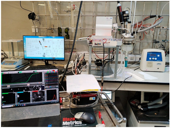
The picture of the laboratory system is shown in Figure 5.
Figure 5.
E-DNC experimental system.
External Heating Loop
The external heating loop consists of a 120 cm long Teflon tube equipped with a carbon-fiber electric heater. It operates at a flow rate of 260 mL/min, and the tube has a volume of approximately 15 mL. This results in a residence time of 3.5 s within the heated tube. Consequently, it takes about 2 min for the full reactor volume (500 mL) to cycle through the loop. The Reynolds number for this flow is approximately 1360, which falls within the laminar flow regime.
5.2. Experimental Procedure
Creatine monohydrate was chosen as a model compound for crystallization due to its wide availability and the absence of known polymorphs under normal conditions [35,36], which simplifies experiments and avoids complications that could arise from polymorphism. Regardless of the experiment type (linear cooling or E-DNC), the initial procedure involved dissolving 15.30 g of creatine monohydrate in 500 mL of distilled water at 55 °C. The suspension was stirred in the crystallizer at 300 rpm until complete dissolution. The solution was then cooled to 35 °C, followed by the addition of seeds (0.153 g, 60–80 µm sieved fraction). The seed fraction was chosen to avoid agglomeration of seeds, and low seed loading should lead to larger crystals at the end of the process. These seeding conditions are common in the pharmaceutical and related industries [37,38]. A process microscope was inserted into the crystallizer with the focal plane set to 25 µm. The experiments then continued with either linear cooling or DNC, depending on the experiment type. This procedure ensured that the initial conditions remained relatively consistent throughout the experiments and that no intentional variance was introduced. The list of experiments and experimental conditions is provided in Table 4.
Table 4.
Experimental conditions.
6. Results and Discussion
6.1. Simulation Results
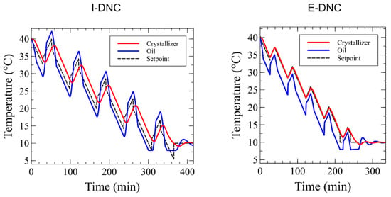
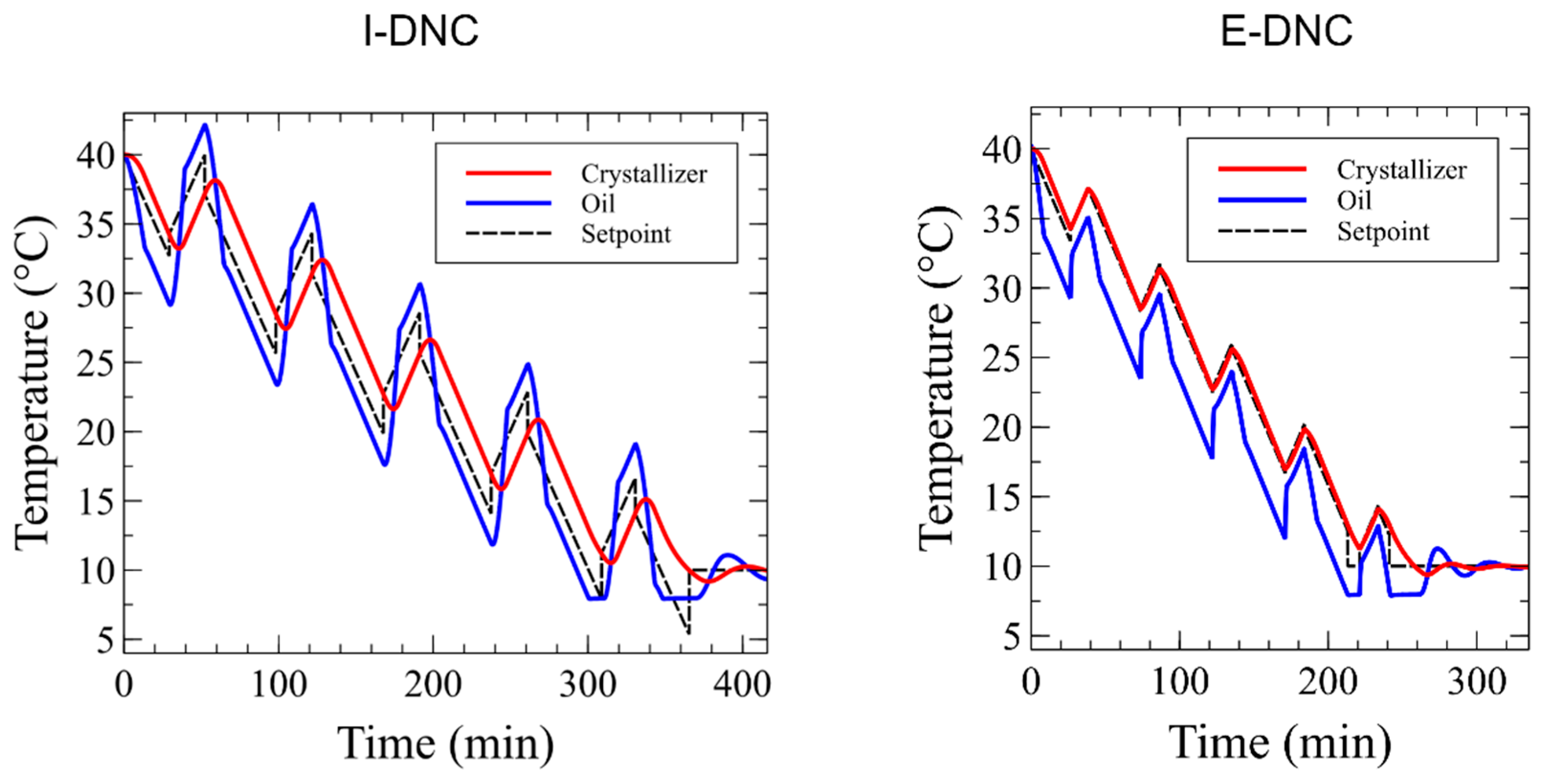
Two simulations were performed, namely I-DNC and E-DNC, with the aim of achieving the same number of heating cycles. A comparison of the temperature responses for I-DNC and E-DNC is shown in Figure 6.
Figure 6.
Simulated temperature responses of external and internal DNC.
As expected, I-DNC has a more inert temperature response compared to E-DNC. As discussed in the conceptual model, this occurs because, in I-DNC, the oil must be heated to a higher temperature than the crystallizer for heat transfer to take place. This is also why a temperature setpoint cannot be followed accurately, in contrast to E-DNC, where it is highly accurate. Energy requirements and process duration differ significantly, as shown in Table 5.
Table 5.
Energy expenditure and process duration.
It can be observed that the E-DNC method studied in simulation uses 37.5% less energy and requires 19.7% less time compared to I-DNC. Therefore, it can be concluded that this method is a valuable improvement worth researching.
6.2. Experimental Results
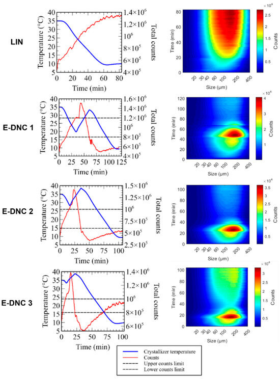
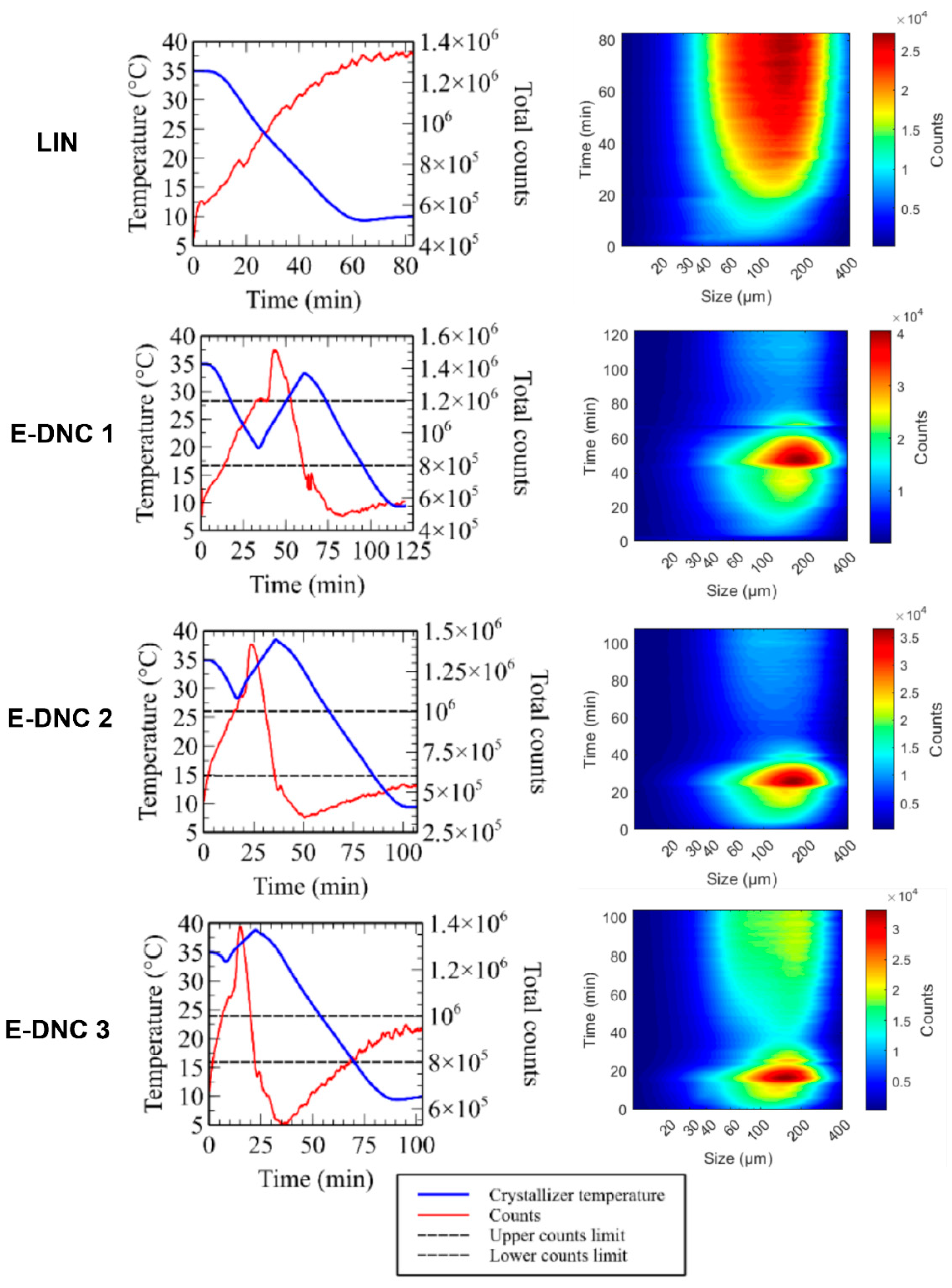
The linear cooling experiment provided information about the expected range of counts and served as a starting point for the E-DNC experiments. Counts stabilized at 1.4 million at the end of linear cooling; therefore, the initial setpoint range for E-DNC1 was set with a slightly lower upper limit of 1.2 million and a lower limit of 0.8 million. The count limits were adjusted in subsequent experiments to obtain a larger crystal size, and the reasoning behind this is explained further. The total counts and CSD changes over time for all experiments are shown in Figure 7.
Figure 7.
Temperature, total counts, and CSD for linear cooling and E-DNC experiments.
In the E-DNC-1 experiment, when the upper count limit was reached, the heating cycle began. This should have immediately lowered the counts as crystals dissolved; however, it is not uncommon for counts to increase at the start of heating when DNC is used [17,39]. When agglomeration is present, heating causes significant deagglomeration, sharply raising the counts [40]. With further heating, crystals began to dissolve, and the count number declined rapidly to a value below the lower count limit. This resulted in a few crystals with a small surface area, unable to grow as quickly as supersaturation changed. The median crystal size at the end was slightly higher compared to linear cooling, but the yield was visibly lower. In the E-DNC-2 experiment, the lower and upper count limits were shifted towards lower values to trigger heating sooner and avoid strong agglomeration. This did not change the outcome dramatically but did result in values closer to the desired count range at the end of the process. In the E-DNC-3 experiment, the heating rate was reduced from 0.5 to 0.35 °C/min to slow down dissolution and rapid count change. The lower count limit was also raised slightly to avoid over-dissolving the crystals. This had the desired effect, leading to a significant increase in median crystal size without visibly lowering the yield.
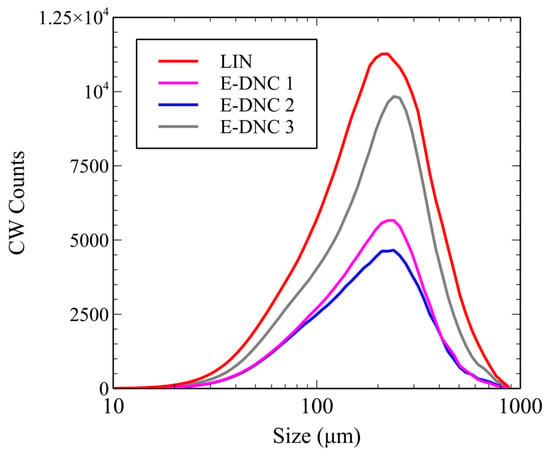
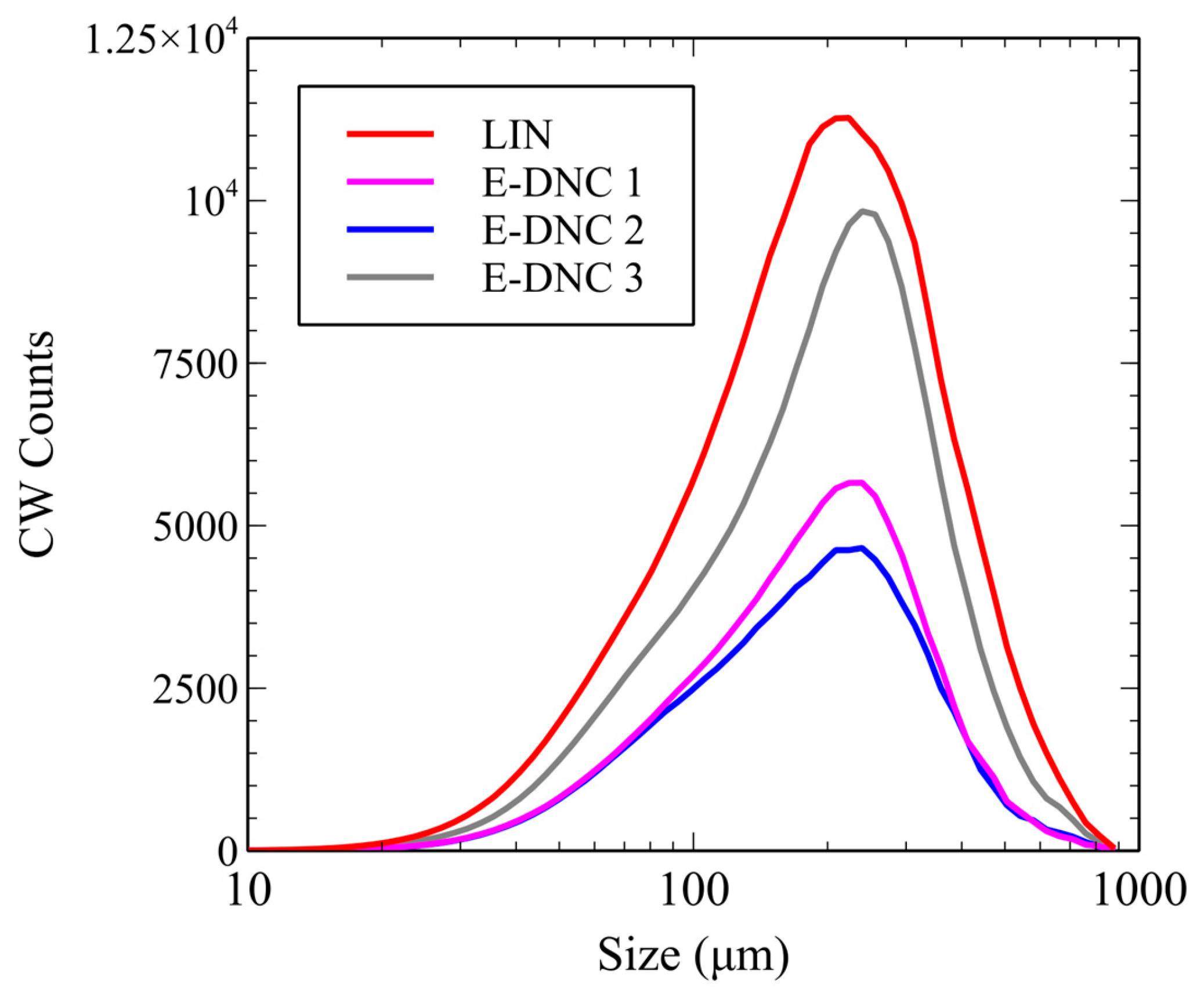
A comparison of CSD at the end of the process is shown in Figure 8, and the median crystal size is given in Table 6.
Figure 8.
CSD at the end of the experiment for LIN and E-DNC experiments.
Table 6.
Median crystal size at the end of the experiment.
It can be observed that with proper DNC parameter tuning, a significantly larger median crystal size is achieved in just three consecutive experiments. Compared to linear cooling, the optimized E-DNC 3 experiment produced a 22.5% larger median crystal size without reducing yield.
7. Conclusions
The work presented in this article introduced and experimentally validated a novel variant of the direct nucleation control method—the external direct nucleation control (E-DNC), which transfers the heating phase from the crystallizer jacket to an external, electrically heated recirculation loop. Conceptual and experimental investigations demonstrated that the proposed configuration successfully eliminates the major drawbacks of internal DNC (I-DNC), namely slow thermal response and high energy demand. By isolating the heating and cooling subsystems and employing a simple state machine control structure, it was possible to remove the thermal short circuit inherently present in previous designs. Simulation results clearly indicate that the external approach allows for faster thermal transitions and significantly reduced overall energy consumption compared to the internal DNC. Specifically, the modeled E-DNC process required 37.5% less energy and achieved a 19.7% shorter batch time. These improvements result from the direct and localized nature of electrical heating, which avoids unnecessary heating of the entire jacket fluid volume and minimizes losses to the surroundings. Furthermore, the use of standard process control structures compatible with industrial PLC systems implies that the concept can be readily implemented at both laboratory and pilot plant scales.
Experimental results obtained with creatine monohydrate crystallization further confirmed the practical applicability of the E-DNC method. In a brief optimization sequence of three experiments, the median crystal size increased by 22.5% compared to linear cooling, confirming that finely controlled partial dissolution can be achieved externally without reducing yield. The experiments also showed that tuning controller parameters, particularly the heating rate and count limits, directly affect the balance between dissolution and growth, enabling systematic improvement of particle size distribution. The constructed E-DNC setup required only standard laboratory components and a low-cost, in-house-built heater controller, demonstrating that the method can be implemented inexpensively without specialized equipment.
From a process systems engineering perspective, the E-DNC method represents progress towards more distributed, electrified, and modular crystallization control systems. As the external heating loop can be easily scaled or parallelized, it aligns well with broader industrial trends in electrification and process intensification. In conclusion, the external direct nucleation control method demonstrates advances in crystallization technology, combining reduced energy consumption, shorter batch durations, and potentially improved product quality.
Supplementary Materials
The following supporting information can be downloaded at: https://www.mdpi.com/article/10.3390/cryst16040248/s1.
Author Contributions
Conceptualization, J.B.S.; methodology, J.B.S.; software, M.R.; validation, N.B.; formal analysis, M.R.; investigation, J.B.S.; resources, N.B.; data curation, M.R.; writing—original draft preparation, J.B.S.; writing—review and editing, J.B.S.; visualization, M.R.; supervision, N.B.; project administration, N.B.; funding acquisition, N.B. All authors have read and agreed to the published version of the manuscript.
Funding
This research was conducted within the Digi-ChemEng-Lab (112113) project, funded by the European Union’s NextGenerationEU fund from source 581—the Recovery and Resilience Mechanism, under the Programme for Financing Public Higher Education Institutions and Public Scientific Institutes.
Data Availability Statement
The original contributions presented in this study are included in the article/Supplementary Materials. Further inquiries can be directed to the corresponding author.
Conflicts of Interest
The authors declare no conflicts of interest.
References
- Chianese, A.; Kramer, H.J. Industrial Crystallization Process Monitoring and Control; Wiley: Hoboken, NJ, USA, 2012. [Google Scholar]
- Tung, H.-H. Crystallization of Organic Compounds: An Industrial Perspective; Wiley: Hoboken, NJ, USA, 2009. [Google Scholar]
- Liu, F.; Bagi, S.D.; Su, Q.; Chakrabarti, R.; Barral, R.; Gamekkanda, J.C.; Hu, C.; Mascia, S. Targeting Particle Size Specification in Pharmaceutical Crystallization: A Review on Recent Process Design and Development Strategies and Particle Size Measurements. Org. Process Res. Dev. 2022, 26, 3190–3203. [Google Scholar] [CrossRef] [Scilit]
- Perini, G.; Salvatori, F.; Ochsenbein, D.R.; Mazzotti, M.; Vetter, T. Filterability prediction of needle-like crystals based on particle size and shape distribution data. Sep. Purif. Technol. 2019, 211, 768–781. [Google Scholar] [CrossRef] [Scilit]
- Košťálová, D.; Svoboda, R.; Kozlová, K.; Nevyhoštěná, M.; Komersová, A. Particle-Size-Determined Crystallization and Dissolution Behavior of Amorphous Griseofulvin. Pharm. Res. 2025, 43, 253–267. [Google Scholar] [CrossRef] [Scilit] [PubMed]
- Orehek, J.; Teslić, D.; Likozar, B. Continuous Crystallization Processes in Pharmaceutical Manufacturing: A Review. Org. Process Res. Dev. 2021, 25, 16–42. [Google Scholar] [CrossRef] [Scilit]
- Liotta, V.; Sabesan, V. Monitoring and feedback control of supersaturation using ATR-FTIR to produce an active pharmaceutical ingredient of a desired crystal size. Org. Process Res. Dev. 2004, 8, 488–494. [Google Scholar] [CrossRef] [Scilit]
- Saleemi, A.N.; Rielly, C.D.; Nagy, Z.K. Comparative investigation of supersaturation and automated direct nucleation control of crystal size distributions using ATR-UV/vis spectroscopy and FBRM. Cryst. Growth Des. 2012, 12, 1792–1807. [Google Scholar] [CrossRef] [Scilit]
- Bakar, M.R.A.; Nagy, Z.K.; Saleemi, A.N.; Rielly, C.D. The impact of direct nucleation control on crystal size distribution in pharmaceutical crystallization processes. Cryst. Growth Des. 2009, 9, 1378–1384. [Google Scholar] [CrossRef] [Scilit]
- Jul-Jørgensen, I.; Oliver, R.; Gernaey, K.V.; Hundahl, C.A. Modernizing non-classical protein crystallization through industry 4.0: Advanced monitoring and modelling utilizing process analytical technology. Chem. Eng. Res. Des. 2024, 204, 382–389. [Google Scholar] [CrossRef] [Scilit]
- Wu, W.L.; Chappelow, C.; Hanspal, N.; Larsen, P.; Patton, J.; Shinkle, A.; Nagy, Z.K. Implementation and application of image analysis-based turbidity direct nucleation control for rapid agrochemical crystallization process design and scale-up. Ind. Eng. Chem. Res. 2022, 61, 14561–14572. [Google Scholar] [CrossRef] [Scilit]
- Borsos, Á.; Szilágyi, B.; Agachi, P.Ş.; Nagy, Z.K. Real-Time Image Processing Based Online Feedback Control System for Cooling Batch Crystallization. Org. Process Res. Dev. 2017, 21, 511–519. [Google Scholar] [CrossRef] [Scilit]
- Zhang, F.; Meng, A.; Long, Y.; Yu, Z.Q.; Yu, S.; Shan, B.; Wang, X.Z.; Xu, Q. Advances and Opportunities Concerning Nucleation Measurement and Control Technology in Crystallization. Org. Process Res. Dev. 2024, 28, 3055–3077. [Google Scholar] [CrossRef] [Scilit]
- Simone, E.; Othman, R.; Vladisavljević, G.T.; Nagy, Z.K. Preventing crystal agglomeration of pharmaceutical crystals using temperature cycling and a novel membrane crystallization procedure for seed crystal generation. Pharmaceutics 2018, 10, 17. [Google Scholar] [CrossRef] [Scilit] [PubMed]
- Orosz, Á.; Szilagyi, E.; Spaits, A.; Borsos, Á.; Farkas, F.; Markovits, I.; Százdi, L.; Volk, B.; Kátainé Fadgyas, K.; Szilágyi, B. Dynamic Modeling and Optimal Design Space Determination of Pharmaceutical Crystallization Processes: Realizing the Synergy between Off-the-Shelf Laboratory and Industrial Scale Data. Ind. Eng. Chem. Res. 2024, 63, 4068–4082. [Google Scholar] [CrossRef] [Scilit]
- Saleemi, A.; Rielly, C.; Nagy, Z.K. Automated direct nucleation control for in situ dynamic fines removal in batch cooling crystallization. CrystEngComm 2012, 14, 2196–2203. [Google Scholar] [CrossRef] [Scilit]
- Sanzida, N.; Nagy, Z.K. Strategic evaluation of different direct nucleation control approaches for controlling batch cooling crystallisation via simulation and experimental case studies. Comput. Chem. Eng. 2019, 130, 106559. [Google Scholar] [CrossRef] [Scilit]
- Sacher, J.B.; Bolf, N.; Sejdić, M. Batch Cooling Crystallization of a Model System Using Direct Nucleation Control and High-Performance In Situ Microscopy. Crystals 2024, 14, 1079. [Google Scholar] [CrossRef] [Scilit]
- Luyben, W.L. Temperature setpoint-ramp control structure for batch reactors. Chem. Eng. Sci. 2019, 208, 115124. [Google Scholar] [CrossRef] [Scilit]
- Kovács, E.A.; Szilágyi, B. A synthetic machine learning framework for complex crystallization processes: The case study of the second-order asymmetric transformation of enantiomers. Chem. Eng. J. 2023, 465, 142800. [Google Scholar] [CrossRef] [Scilit]
- Orosz, A.; Bosits, M.H.; Pusztai, E.; Pataki, H.; Szalay, Z.; Demeter, A.; Szilágyi, B. Diastereomer salt crystallization: Comprehensive process modeling and DoE-driven comparison of custom-coded and user-friendly simulators. Chem. Eng. J. 2023, 473, 145257. [Google Scholar] [CrossRef] [Scilit]
- Breveglieri, F.; Bodák, B.; Mazzotti, M. Deracemization via Periodic and Non-periodic Temperature Cycles: Rationalization and Experimental Validation of a Simplified Process Design Approach. Org. Process Res. Dev. 2021, 25, 2551–2565. [Google Scholar] [CrossRef] [Scilit]
- Szilágyi, B. Direct design of crystallization-induced deracemization through direct nucleation control (DNC). J. Ind. Eng. Chem. 2025, 151, 502–512. [Google Scholar] [CrossRef] [Scilit]
- Simone, E.; Zhang, W.; Nagy, Z.K. Application of process analytical technology-based feedback control strategies to improve purity and size distribution in biopharmaceutical crystallization. Cryst. Growth Des. 2015, 15, 2908–2919. [Google Scholar] [CrossRef] [Scilit]
- Hansen, T.B.; Simone, E.; Nagy, Z.K.; Qu, H. Process Analytical Tools to Control Polymorphism and Particle Size in Batch Crystallization Processes. 2017. Available online: http://pubs.acs.org (accessed on 16 January 2021).
- Simone, E.; Klapwijk, A.R.; Wilson, C.C.; Nagy, Z.K. Investigation of the Evolution of Crystal Size and Shape during Temperature Cycling and in the Presence of a Polymeric Additive Using Combined Process Analytical Technologies. Cryst. Growth Des. 2017, 17, 1695–1706. [Google Scholar] [CrossRef] [Scilit] [PubMed]
- Bereczki-Horváth, L.V.; Szilágyi, B. Automatic Design of Wet-Milling-Integrated Batch Crystallization Processes by Process Analytical Technology-Based Split-Range Direct Nucleation Control. Org. Process Res. Dev. 2026. [Google Scholar] [CrossRef] [Scilit]
- Saleemi, A.N.; Steele, G.; Pedge, N.I.; Freeman, A.; Nagy, Z.K. Enhancing crystalline properties of a cardiovascular active pharmaceutical ingredient using a process analytical technology based crystallization feedback control strategy. Int. J. Pharm. 2012, 430, 56–64. [Google Scholar] [CrossRef] [Scilit]
- Szilágyi, B. External fine particle removal for crystallization processes: Introduction and systematic comparison with the temperature cycling-based fines removal. Chem. Eng. Process. 2022, 179, 109074. [Google Scholar] [CrossRef] [Scilit]
- Kacker, R.; Radoiu, M.; Kramer, H.J.M. Novel Design Integrating a Microwave Applicator into a Crystallizer for Rapid Temperature Cycling. A Direct Nucleation Control Study. Cryst. Growth Des. 2017, 17, 3766–3774. [Google Scholar] [CrossRef] [Scilit]
- Kacker, R.; Salvador, P.M.; Sturm, G.S.; Stefanidis, G.D.; Lakerveld, R.; Nagy, Z.K.; Kramer, H.J. Microwave Assisted Direct Nucleation Control for Batch Crystallization: Crystal Size Control with Reduced Batch Time. Cryst. Growth Des. 2016, 16, 440–446. [Google Scholar] [CrossRef] [Scilit]
- Xiouras, C.; Kuijpers, K.; Fanfair, D.; Dorbec, M.; Gielen, B. Enabling Technologies for Process Intensification in Pharmaceutical Research and Manufacturing; Elsevier Ltd.: Amsterdam, The Netherlands, 2023. [Google Scholar] [CrossRef] [Scilit]
- Wang, J.; Li, F.; Lakerveld, R. Process Intensification for Pharmaceutical Crystallization; Elsevier B.V.: Amsterdam, The Netherlands, 2018. [Google Scholar] [CrossRef] [Scilit]
- Ostergaard, I.; Szilagyi, B.; De Diego, H.L.; Qu, H.; Nagy, Z.K. Polymorphic Control and Scale-Up Strategy for Antisolvent Crystallization Using a Sequential Supersaturation and Direct Nucleation Control Approach. Cryst. Growth Des. 2020, 20, 5538–5550. [Google Scholar] [CrossRef] [Scilit]
- Jäger, R.; Purpura, M.; Shao, A.; Inoue, T.; Kreider, R.B. Analysis of the efficacy, safety, and regulatory status of novel forms of creatine. Amino Acids 2011, 40, 1369–1383. [Google Scholar] [CrossRef] [Scilit]
- Kreider, R.B.; Jäger, R.; Purpura, M. Bioavailability, Efficacy, Safety, and Regulatory Status of Creatine and Related Compounds: A Critical Review. Nutrients 2022, 14, 1035. [Google Scholar] [CrossRef] [Scilit]
- Pickles, T.; Svoboda, V.; Marziano, I.; Brown, C.J.; Florence, A.J. Integration of a model-driven workflow into an industrial pharmaceutical facility: Supporting process development of API crystallization. CrystEngComm 2024, 26, 4678–4689. [Google Scholar] [CrossRef] [Scilit]
- Pickles, T.; Leghrib, Y.; Weisshaar, M.; Goncharuk, M.; Timperman, P.; Doherty, T.; Ford, D.D.; Moores, J.; Florence, A.J.; Brown, C.J. Automated scale-up crystallisation DataFactory for model-based pharmaceutical process development: A Bayesian case study. Digit. Discov. 2025, 4, 2025–2032. [Google Scholar] [CrossRef] [Scilit]
- Gao, Y.; Zhang, T.; Ma, Y.; Xue, F.; Gao, Z.; Hou, B.; Gong, J. Application of pat-based feedback control approaches in pharmaceutical crystallization. Crystals 2021, 11, 221. [Google Scholar] [CrossRef] [Scilit]
- Zhang, H.; Du, S.; Wang, Y.; Xue, F. Prevention of Crystal Agglomeration: Mechanisms, Factors, and Impact of Additives. Crystals 2024, 14, 676. [Google Scholar] [CrossRef] [Scilit]

Disclaimer/Publisher’s Note: The statements, opinions and data contained in all publications are solely those of the individual author(s) and contributor(s) and not of MDPI and/or the editor(s). MDPI and/or the editor(s) disclaim responsibility for any injury to people or property resulting from any ideas, methods, instructions or products referred to in the content. |
© 2026 by the authors. Licensee MDPI, Basel, Switzerland. This article is an open access article distributed under the terms and conditions of the Creative Commons Attribution (CC BY) license.