Article

Tandem Neural Network Based Design of Acoustic Metamaterials for Low-Frequency Vibration Reduction in Automobiles

1
State Key Laboratory of Advanced Vehicle Integration and Control, China FAW Group Co., Ltd., Changchun 130013, China
2
College of Mechanical Engineering, Southwest Jiaotong University, Chengdu 610031, China
3
Key Laboratory of New Energy Vehicles Intelligent Design and Manufacturing in Universities of Sichuan Province, Chengdu 611730, China
*
Author to whom correspondence should be addressed.
Crystals 2025, 15(8), 676; https://doi.org/10.3390/cryst15080676
Submission received: 6 June 2025 / Revised: 21 July 2025 / Accepted: 23 July 2025 / Published: 24 July 2025
(This article belongs to the Special Issue Metamaterials and Their Devices, Second Edition)

Abstract

Automotive NVH (Noise, Vibration, and Harshness) performance significantly impacts driving comfort and traffic safety. Vehicles exhibiting superior NVH characteristics are more likely to achieve consumer acceptance and enhance their competitiveness in the marketplace. In the development of automotive NVH performance, traditional vibration reduction methods have proven to be mature and widely implemented. However, due to constraints related to size and weight, these methods typically address only high-frequency vibration control. Consequently, they struggle to effectively mitigate vehicle body and component vibration noise at frequencies below 200 Hz. In recent years, acoustic metamaterials (AMMs) have emerged as a promising solution for suppressing low-frequency vibrations. This development offers a novel approach for low-frequency vibration control. Nevertheless, conventional design methodologies for AMMs predominantly rely on empirical knowledge and necessitate continuous parameter adjustments to achieve desired bandgap characteristics—an endeavor that entails extensive calculations and considerable time investment. With advancements in machine learning technology, more efficient design strategies have become feasible. This paper presents a tandem neural network (TNN) specifically developed for the design of AMMs. The trained neural network is capable of deriving both the bandgap characteristics from the design parameters of AMMs as well as deducing requisite design parameters based on specified bandgap targets. Focusing on addressing low-frequency vibrations in the back frame of automobile seats, this method facilitates the determination of necessary AMMs design parameters. Experimental results demonstrate that this approach can effectively guide AMMs designs with both speed and accuracy, and the designed AMMs achieved an impressive vibration attenuation rate of 63.6%.

1. Introduction

The doors, seats, and roofs of automobiles are prone to low-frequency resonance, resulting in significant vibration and noise. These low-frequency vibrations not only affect driving comfort, but can also lead to premature component failure, increasing safety hazards. The bandgap in AMMs usually refers to the fact that within a certain frequency range of periodic materials, the material strongly suppresses the propagation of vibration waves or sound waves, resulting in the inability of waves within this frequency band to propagate within the material. That is, in the bandgap frequency range, vibrations or sound waves are effectively blocked or attenuated. Traditional damping materials are limited by their mass and load-bearing capacity, and it is difficult to achieve the performance of lightweight, high-strength, and low-frequency broadband bandgap at the same time [1,2]. Traditional structural vibration isolators are generally used for medium and high frequency vibration suppression, which has certain limitations.
AMMs [3,4] are a class of structural materials that are artificially designed to have acoustic properties that are not found in natural materials. Therefore, AMMs show great potential in noise reduction [5,6,7,8,9], vibration damping [10,11], energy harvesting [12,13], acoustic Metasurfaces [14,15,16], and directional wave propagation [17,18,19]. The use of acoustic metamaterials for low-frequency vibration reduction has been a hot topic of research for various research groups in the field of metamaterials over the years. Ping He [20] proposed a new type of composite acoustic metamaterial to address the low-frequency vibrations below 0–100 Hz generated by in-orbit rotating mechanical equipment. Lixia Li [21] proposed an acoustic black hole radial elastic metamaterial (AREM). The AREM accumulates energy at the tip of the black hole unit, which can trigger the local resonance (LR) effect and couple with the Bragg scattering (BS) effect, thereby opening up a strongly attenuating broadband at extremely low frequencies. Jinchen Zhou [22] utilized the so-called “trampoline effect” to design a low-frequency, broadband negative Poisson’s ratio structural acoustic metamaterial (NPRS-SC). The first low-frequency band gap range of NPRS-SC is 66.1 to 281.1 Hz; compared with traditional structures, it has a lower starting frequency and a wider bandgap. Although the application of AMMs has become very widespread, there are still certain thresholds. This is because the relationship between the parameter space of AMMs and the target bandgap is highly nonlinear. Traditional finite element methods (FEM) can usually only perform forward calculations, that is, calculate the target bandgap from the parameters. FEM not only requires the designer to have significant experience, but also must invest a lot of time and energy to constantly try and make mistakes and adjustments in order to finally obtain the suitable target bandgap. However, the problem of inverse design, that is, obtaining the parameters of the AMMs we need from the target bandgap, is difficult at present. Generally speaking, the methods of inverse design include gradient optimization, evolutionary algorithm, and topology optimization, but with the increase of structural complexity, the parameter space also shows geometric multiplication, and the time spent also increases greatly. Therefore, the choice of AMMs design method is crucial.
Machine learning (ML) is a technology that allows computers to automatically learn patterns from data and make predictions or decisions, driving innovation in structural design and continuous technological advancement. In recent years, deep learning (DL), as a branch of machine learning, has been studied in materials science [23], chemistry [24], and physics [25] because of its excellent performance in dealing with complex pattern recognition tasks. With the continuous development of machine learning technology, researchers have been influenced by this technology and have begun to pay attention to the parameter design and performance prediction of materials. The most important advantage of deep learning is its ability to automatically extract high-level features from large amounts of complex data and make effective representations, which can find potential connections between AMMs parameters and performance, and is widely used in AMMs research [26,27,28,29]. Specifically, the machine learning methods used by researchers in AMMs include multilayer perceptron (MLP) [30,31], convolutional neural network (CNN) [32,33], tandem neural network (TNN) [34,35], generative adversarial network (GAN) [36,37], variational autoencoder (VAE) [38], and reinforcement learning (RL) [39,40], all of which greatly improve the design efficiency of AMMs.
At present, there are various machine learning methods in AMMs design. The frequently used methods include MLP, CNN, TNN, GAN, VAE, and RL. MLP is suitable for general supervised learning tasks, but it performs poorly in handling high-dimensional data and has non-uniqueness issues in inverse design. Usually, in AMMs research, it also needs to be combined with other algorithms. CNN is highly suitable for processing image data and spatial data and can effectively extract local features in structural design. In AMMs research, it is usually necessary to represent the unit cell structure with binary images. The finer the geometric features of the unit cell structure, the higher the computational cost. Moreover, the manufacturability of the unit cell structure needs to be considered, so the solid regions need to be interconnected. Both VAE and GAN are suitable for generation tasks. VAE has good stability, but it takes a long time to learn and has limited capabilities. Usually, the quality of the generated samples is not as good as that of GAN. GAN can generate high-quality samples, but it requires a large amount of computing resources and data, has complex parameter tuning, and requires a long training time. RL is suitable for solving dynamic decision-making problems, but it has a slow convergence speed, requires a large amount of interaction data, and the modeling design of the environment is complex and prone to getting stuck in local optimal solutions. TNN has high flexibility. In AMMs research, it can both complete forward design and inverse design. In the inverse design of multiple parameters, it can also overcome the non-uniqueness problem and converge quickly. The training time is short, but it requires a large amount of dataset support. This paper focuses on enhancing the inverse design efficiency of AMMs. TNN can converge rapidly in the inverse design of AMMs, with short training time and high accuracy. After training, it can not only quickly obtain the bandgap characteristics from the design parameters of AMMs but also obtain the required design parameters through the bandgap target of AMMs. Even if a large amount of data is needed for support, this is still acceptable.
In this paper, the method of tandem neural network is applied to the study of AMMs. The purpose is to establish the mutual mapping relationship between the design parameters and the bandgap characteristics, then determine the bandgap range from the vibration characteristics measured by the vehicle seat, and obtain the design parameters from the above method and carry out the final experimental verification. The rest of the structure of this paper is as follows: Section 2 describes the finite element calculation method and parametric modeling of AMMs to obtain the sample set. Section 3 introduces the structure and training details of TNN for AMMs design and also verifies the accuracy of TNN. Section 4 uses inverse design network to design AMMs for low-frequency vibration of car seats and install them in car seats for experimental verification. Section 5 summarizes this experimental study.

2. Parametric Modeling and Sample Set of AMMs

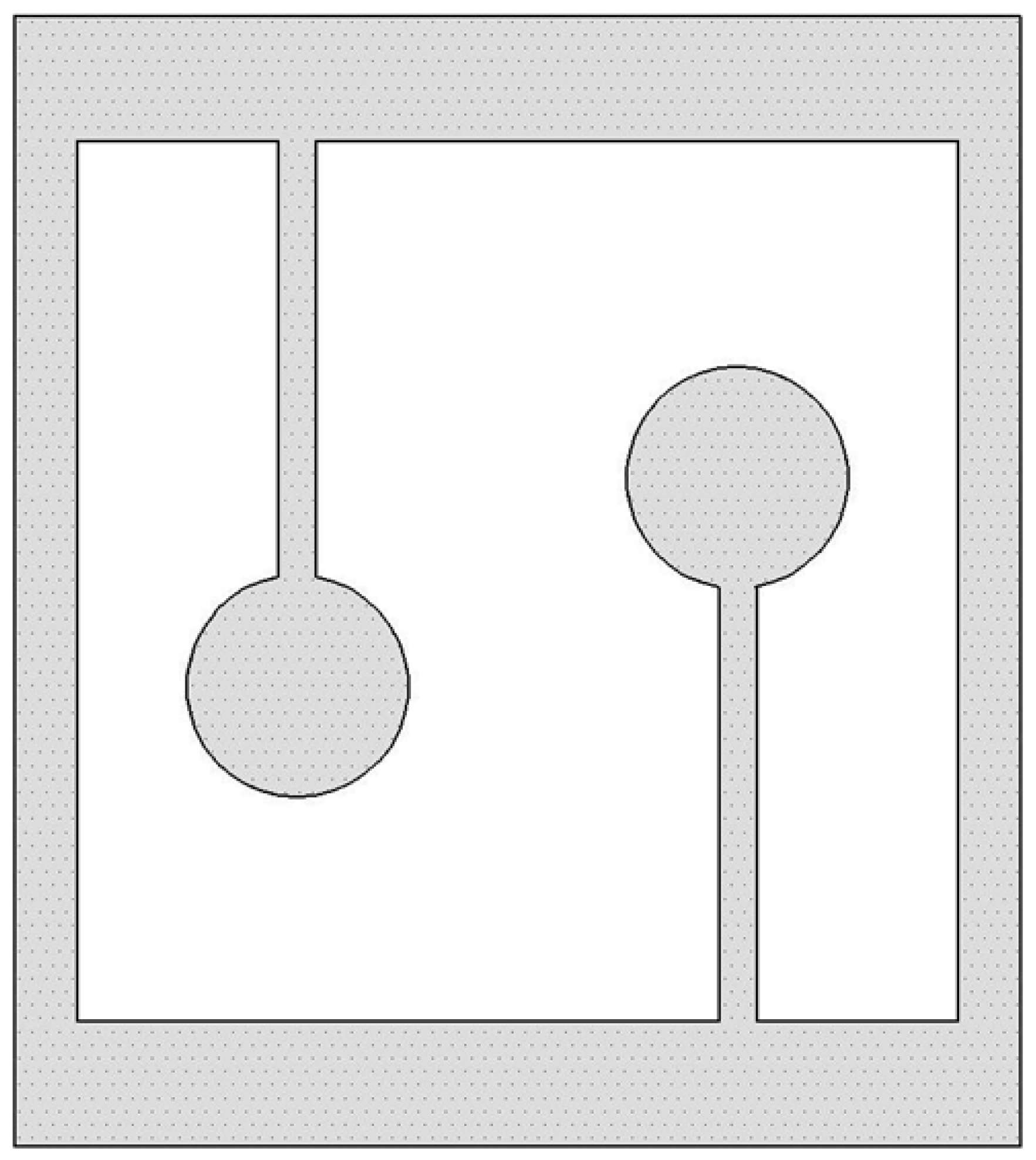
2.1. Basic Unit Structure of AMMs

Acoustic metamaterials are generally classified into Bragg Scattering Metamaterials and Local Resonance Metamaterials. Bragg Scattering Metamaterials are based on the Bragg scattering phenomenon of sound waves in periodic structures. Their characteristic is the design of regular periodic structures, which will produce interference effects within a specific frequency range, causing the reflection or transmission of sound waves to be interrupted, thereby forming an acoustic band gap. The working principle of local resonant metamaterials is based on the resonance phenomenon of local structures. These materials usually contain elastic elements or mass elements inside, which can generate resonance at specific frequencies. By ingeniously designing these resonant frequencies, local structures can significantly reduce the propagation of sound waves at specific frequencies. The design of this metamaterial does not require the structure to be periodic but relies on local resonant phenomena within it. The AMMs in this study belong to local resonance metamaterials. The basic unit is composed of a square frame and two local resonance units with the same additional mass. The position of the additional mass is the circular region of the two local resonance units, as shown in Figure 1. When AMMs receive frequency excitation from an external vibration source, local resonant units vibrate, and when the frequency of the elastic wave is close to the resonant frequency of the resonant unit, these local resonant elements absorb and hinder the propagation of sound waves at that frequency, forming a bandgap. In addition, the additional mass at the local resonant unit position can reduce the resonant frequency to achieve vibration control in the low frequency range.

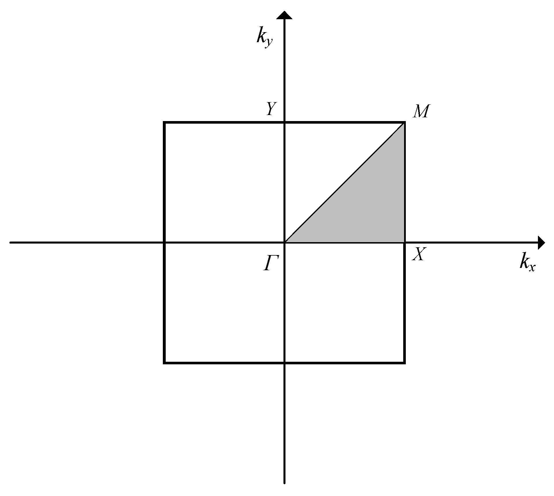
2.2. Bandgap Solution of AMMs

AMMs are arranged in a periodic arrangement, and according to Bloch’s theorem, the displacement field of a periodic structure can be expressed as follows:
u ( r ) = U k ( r ) e i ( k r )
where k is Bloch wave vector, r is position vector, and u ( r ) is amplitude function. Substituting Equation (1) into the propagation of the governing Equation (2), it can be transformed into the eigenvalue equation of the cell using finite element discretization:
( K ω 2 M ) u ( ν ) = 0
where K is the structural stiffness matrix and M is the structural mass matrix. Due to periodicity, the wave vector can be limited to the first Brillouin zone, as shown in Figure 2, and the bandgap curve can be accurately obtained by searching for wave vector points (ΓX, XM, and MΓ) on the Brillouin zone boundary. Considering the computational cost of the training data, only the first four bandgap curves are calculated, and the parameter sweep range of k of the wave vector is 0–3 and the step size is 0.05.

2.3. Dataset of AMMs with Different Design Parameters

In general, DL requires a sufficient amount of data of good quality to obtain accurate results. Therefore, it is necessary to obtain a dataset with a large number of AMMs samples. In the simulation and experimental tests, the square frame of the AMMs is constrained, that is, the size parameters of the square frame do not affect the resonant frequency of the resonant unit. The parameters that affect the resonant frequency of the basic unit are shown in Figure 3. The four design parameters are the thickness of the cantilever beam (a), the length from the cantilever beam to the center of the circle (b), the radius of the circular area (r), and the additional mass within the area of a single circle (m). The remaining parameters that do not affect the bandgap range are shown in Figure 3, with the unit being millimeters.
In order to avoid interference between the resonant element and the square frame and to obtain high-quality data, the range of variable A is set to 2–10 mm, the range of variable B is set to 15–40 mm, the range of variable r is set to 5–15 mm, and the range is set to 0–100 g of variable m. Using the Latin hypercube (LHS) sampling method, 1024 sets of different parameters were obtained and simulated with COMSOL Multiphysics® 6.2 to extract the upper and lower limits of the bandgap of each model in the band diagram, and the 1024 sets of data were used for deep learning training. This article provides two methods for extracting the upper and lower limits of the band gap of 1024 groups of models. Taking the band gap of AMMs in this paper as an example, the lower limit of the band gap is the frequency when the wave vector of the first dispersion curve is k = 2, and the upper limit of the band gap is the frequency when the wave vector of the second dispersion curve is k = 0.05 or k = 2.95. At this point, the upper and lower limits of the bandgap of 1024 groups of models can be calculated and extracted at one time through COMSOL’s parametric scanning function, or the upper and lower limits of the bandgap of each group of models can be extracted through the co-simulation of MATLAB R2024a and COMSOL.

3. AMMs Design Method Based on TNN

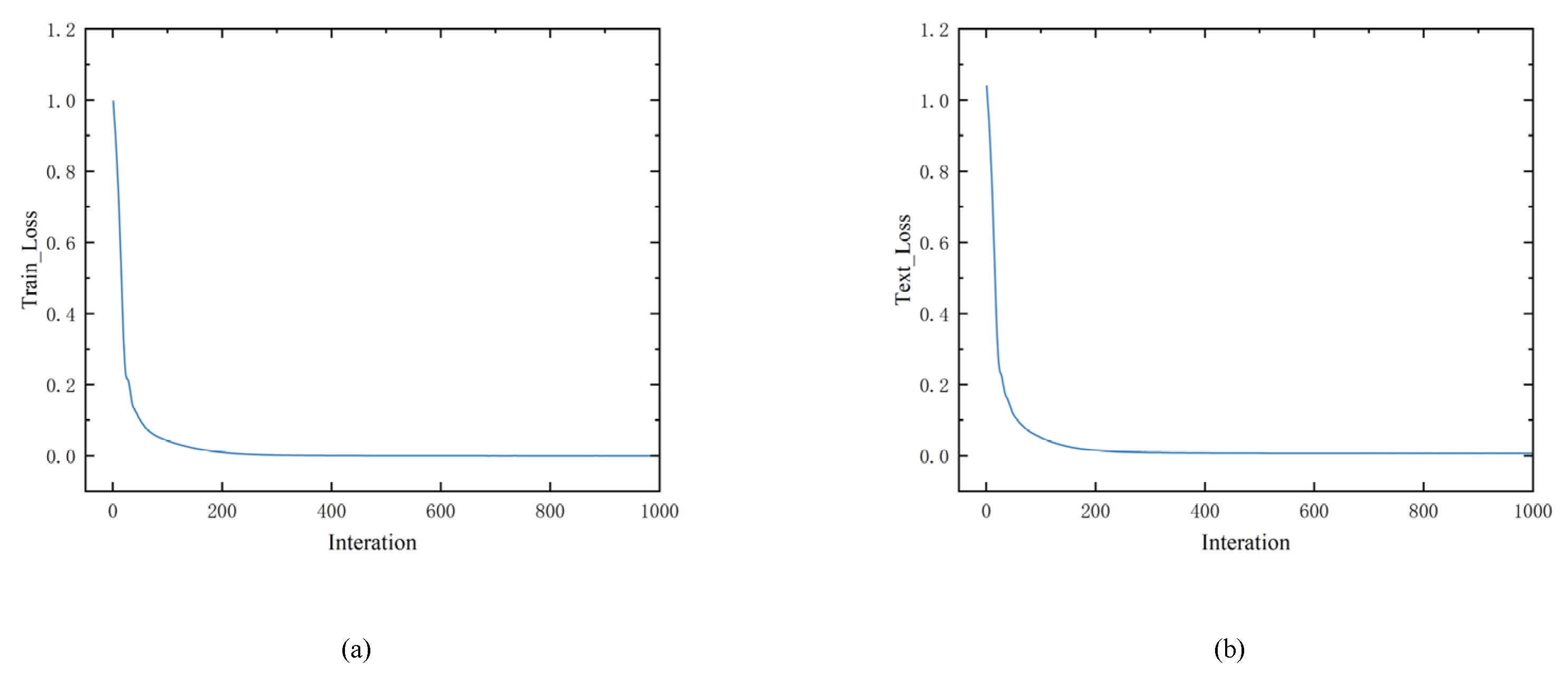
3.1. The Framework of TNN for AMMs

This section introduces deep learning frameworks for AMMs design, such as TensorFlow, PyTorch, MXNet, and JAX. PyTorch is known for its “flexibility, ease of use, and active community”, which is very suitable for academic research and rapid development of industrial applications, so PyTorch 2.6.0+cpu was used as the software environment in this study.

3.1.1. Forward Pretraining Network

The tandem neural network consists of a pre-trained forward network and an inverse design network, and the structure of the tandem neural network is shown in Figure 4.
The pre-trained network is a standard supervised learning network that implements forward mapping of AMMs design parameters to bandgap characteristics. In addition, the pre-trained network after training retains weights and biases that are used to help train the inverse-engineered network. Supervised learning is a machine learning method in which the model is trained on labeled data, meaning that each input sample has a corresponding correct output. During the training process, the model constantly adjusts its own parameters to reduce the difference between the prediction results and the real labels to learn the mapping relationship between input and output. The input layer of the pre-trained network is the design parameters a, b, r, and m, the hidden layer is 3 layers, the number of nodes is 128, 128, and 64, and the output layer is the upper and lower limits of the bandgap.
Before training a neural network, the input data of the training needs to be preprocessed, and the use of preprocessed data can speed up the convergence speed and improve the stability of the training. The methods of data preprocessing are generally standardization or normalization. In this paper, the method of data standardization is adopted. The activation function of the model is the ReLU activation function, and Equation (3) is the mathematical expression of ReLU, which can alleviate the gradient vanishing problem and accelerate the training process. The model uses the mean square error function (MSE) as the loss function, as shown in Equation (4), to quantify the difference between the predicted value and the true value. The adjustment of the learning rate is shown in Equation (5), where αt is the first learning rate at step t; α0 is the initial learning rate; γ is the attenuation coefficient (0 < γ < 1); and t denotes the number of rounds during training. The initial learning rate was 0.001 and was optimized with the Adam optimizer.
f x = m a x ( 0 , x )
MSE ( y , y ) = i = 1 n ( y i y i ) n
αt = α0 × γt

3.1.2. Inverse Design Network

The ultimate goal of the inverse design network is to deduce the design parameters from the required frequency bandgap, and its structure is exactly symmetrical to the pre-trained network. In the design process of AMMs, a set of determined design parameters will correspond to a set of determined bandgap ranges, and a set of determined bandgap ranges will have a variety of design parameters corresponding to them, that is, there is a problem of non-unique solution in inverse design. However, the use of pre-trained networks to assist in inverse design of networks can better overcome this problem. The inverse design network usually outputs multiple sets of design parameters during the training process, and these sets of parameters will be evaluated by the pre-trained network, and the pre-trained network will select the one with the lowest loss, that is, the set of design parameters corresponding to the one with the lowest output loss.
The complete training process is shown in Figure 5. The first is the training of the pre-trained network, the specific details of which have been described in detail above and will not be repeated here. It is important to note that the weights and biases in the pre-trained network are no longer updated after the training is completed. The second is the training of the tandem neural network, which consists of an inverse design network and a pre-trained network, and the output of the inverse design network is used as the input of the pre-trained network. It should also be noted that the pre-trained network during the training process of the tandem neural network has been trained before, and the update of weights and biases only occurs in the inverse design network, and the input and output are both bandgap ranges. Finally, after the training of the tandem neural network is completed, the inverse design network is separated from the tandem neural network as an independent neural network model; the weight and bias of the inverse design network are also fixed, and the inverse design network can output design parameters according to the required bandgap range.

3.2. Forward and Inverse Design Results Through the TNN

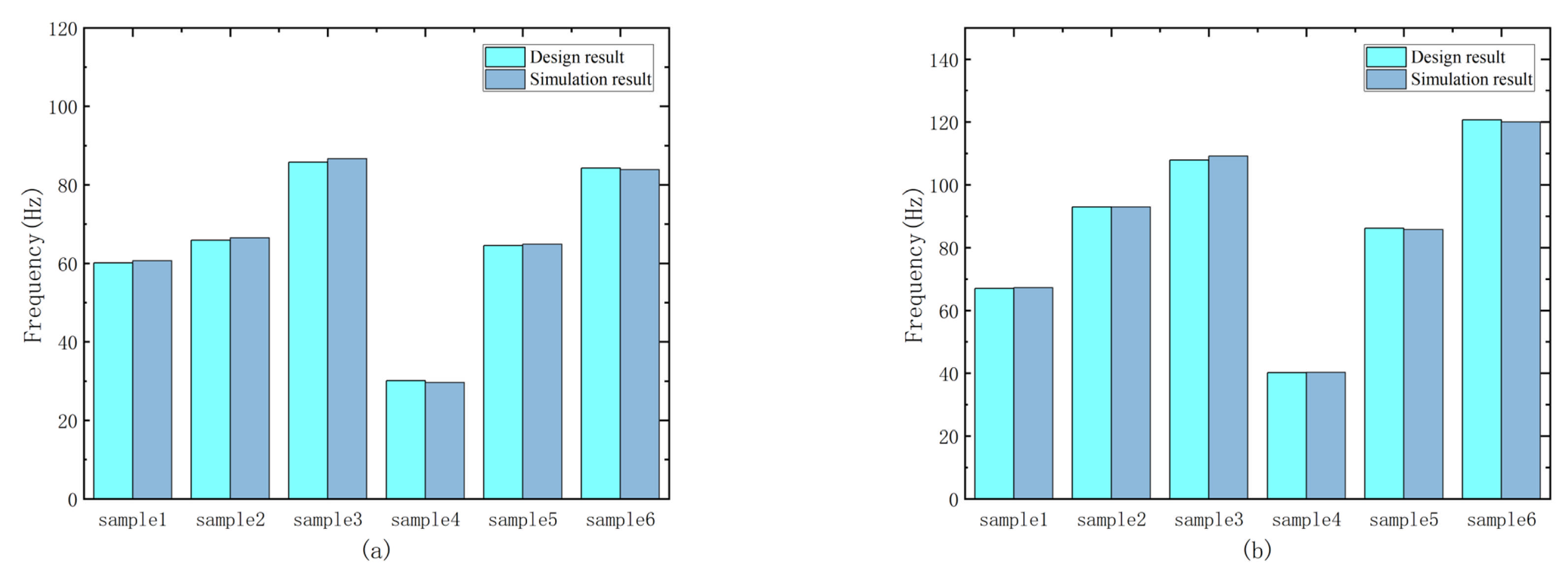
3.2.1. Forward Design of Bandgap Range Based on Design Parameters

In the pre-trained network, 80% of the 1024 sets of data obtained were divided into training sets, and the remaining 20% were divided into test sets. After multiple iterations of training on the pre-trained network, the loss function is used to measure the gap between the output of the model and the target value so as to evaluate the training effect of the pre-trained network. The training process and all numerical experiments were performed on a Chinese PowerColor AMD Radeon RX 6750 GRE 10 GB GPU and a Chinese AMD Ryzen 5 7500F CPU, but the actual CPU-only version of PyTorch was installed because the GPU did not have CUDA cores. Figure 6a,b represents the training loss function curve and the test loss function curve for the first 1000 iterations of pre-training, respectively. At 200 iterations, it can be found that the loss functions of training and testing converge to a very small value, which indicates that the pre-trained network has been well trained. The total time spent on 1000 iterations of the pre-trained network is 1.22 s, and the average time of one iteration is 0.00122 s.
The forward design of AMMs can be achieved through a pre-trained network, and the bandgap range can be quickly derived by inputting design parameters. To test the network performance, we randomly input six sets of design parameters and use the pre-trained network and simulation software to obtain the bandgap range. Table 1 shows the comparison of the bandgap results obtained by different methods for these six sets of design parameters, and the error rate is the average error between the predicted upper and lower limits and the upper and lower limits calculated by simulation. Figure 7 shows the upper and lower limits of the bandgap obtained by the network output and simulation calculations. The upper and lower limits of the bandgap obtained by the network are almost the same as those obtained by the simulation calculation, and the error rate is also very low. It can be concluded that the accuracy of the forward prediction of the pre-trained network is very high.

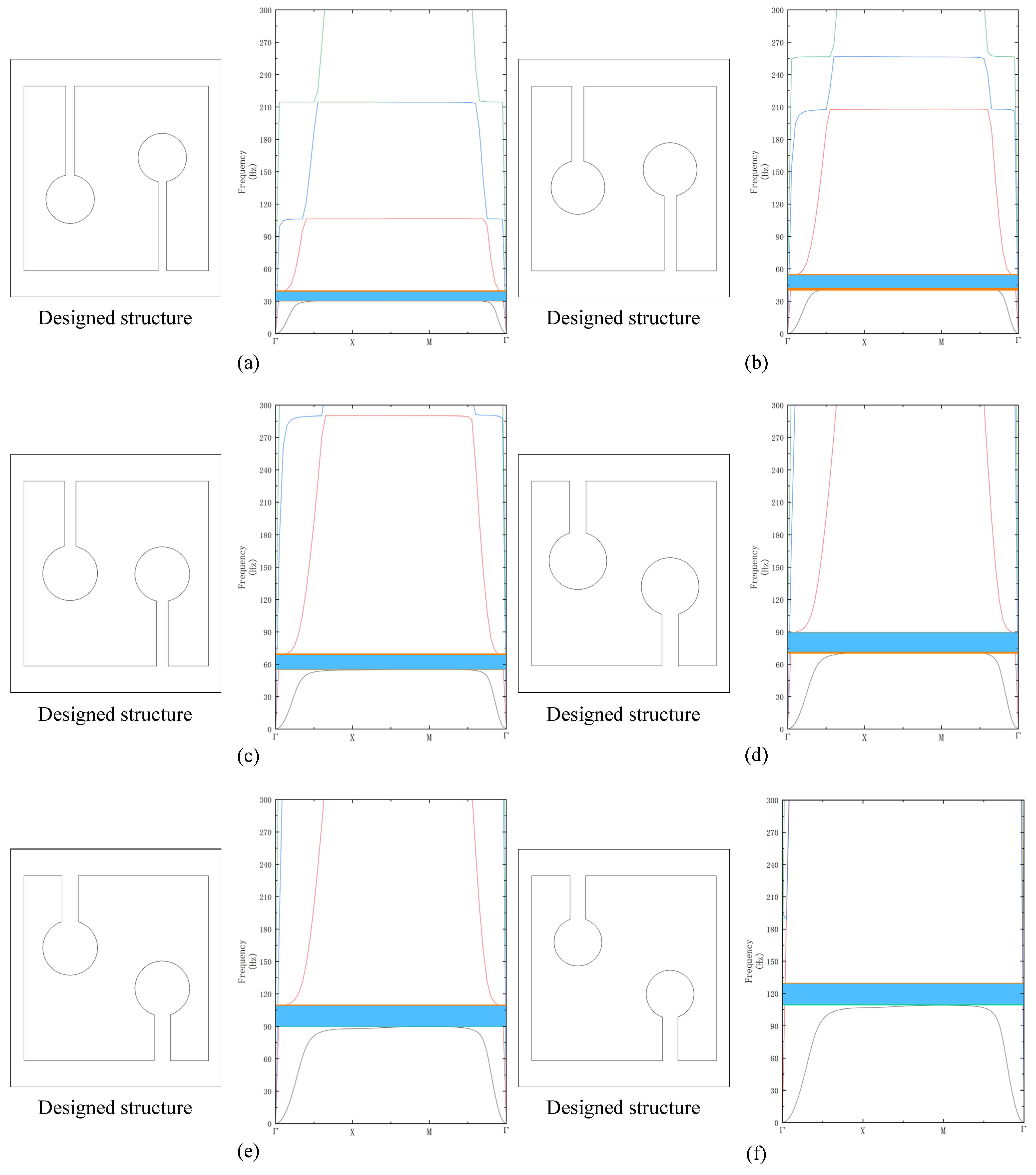
3.2.2. Inverse Design of Design Parameters Based on Bandgap Range

During the inverse design of the experiment, the loss is defined as the mean square error between the actual bandgap range and the predicted bandgap range in the tandem neural network. During the training process, the best model is obtained by minimizing the bandgap range of the input samples and the bandgap range of the output of the tandem neural network. The training loss function curve is shown in Figure 8, and the tandem neural network has been well trained. The total time spent on training 1000 iterations of a tandem neural network is 1.84 s, and the time for each iteration is 0.00184 s.
After the training of the tandem neural network is completed, the inverse design network is extracted separately, and the inverse network can output the design parameters of AMMs according to the input bandgap range. The design parameters obtained by the inverse design network were entered into the COMSOL software to obtain the simulation results, and the input bandgap was compared with the simulation results. As shown in Table 2, the difference between the predicted results of the model and the simulation results is small. As shown in Figure 9, the orange portion represents the desired bandgap range, the green portion represents the simulated bandgap range, and the blue portion represents their overlapping portion. The range of the input bandgap is basically consistent with the range calculated by the simulation, which proves the effectiveness of the deep learning method in the design of AMMs.

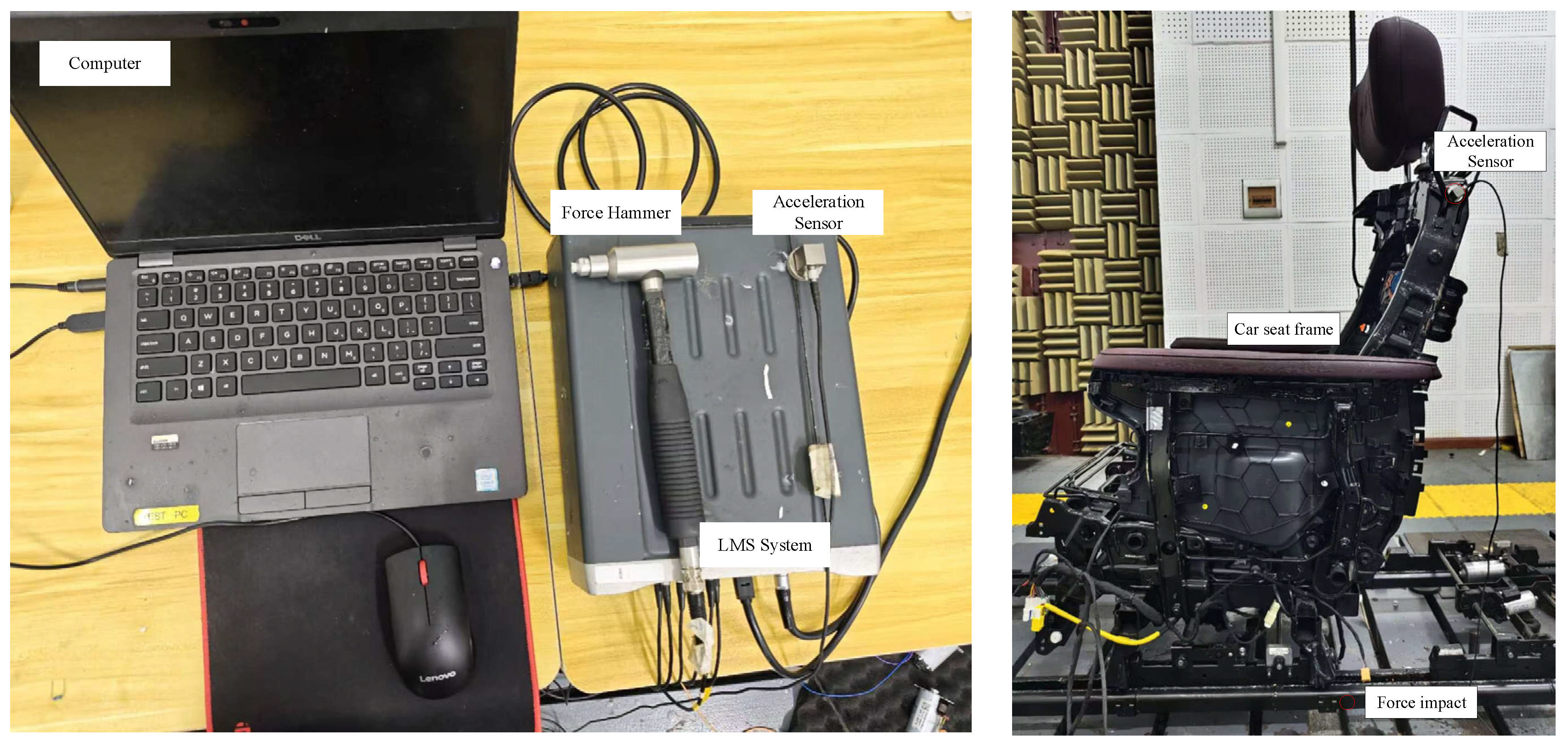
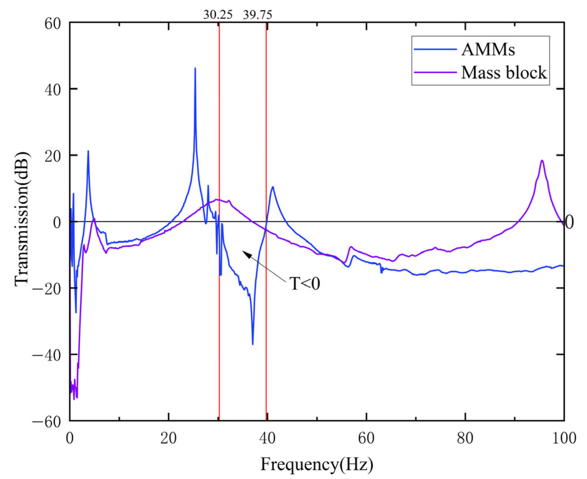
4. Experimental Verification

In the process of driving, due to the influence of the outside world and self-excitation, the doors, seats, roof, and other parts are prone to low-frequency resonance, resulting in obvious vibration and noise. The car seat is an important component that directly contacts the occupants on the entire vehicle and is also a key component that affects the NVH performance of the entire vehicle. The low-frequency vibration and noise of car seats can easily cause driver fatigue, affecting the riding experience and safety.
We selected the problem frequency at the seat back frame of the vehicle to design the AMMs, and we used the inverse design network to design AMMs and experiment on car seats. Figure 10 shows the experimental equipment and measurement scheme, which consists of an LMS system, a hammer, an accelerometer, and a laptop computer. An accelerometer is installed at the seat frame of the vehicle, a hammer is used to tap the position of the rail under the seat, and the frequency response curve in the range of 0–100 Hz is obtained through the LMS system, as shown in Figure 11. We can find that the vibration response of the vehicle seat back frame in the frequency range of 33–40 Hz is large, we set the required bandgap frequency to 32–41 Hz to input the inverse design network, and we get the results shown in Figure 12a, and the bandgap characteristics are shown in Figure 12b. The bandgap range calculated by simulation is 32.5–39.8 Hz.
The AMMs in Figure 12a were processed. The processing thickness is 0.9 mm, the material is 304 stainless steel, and the material properties are as follows: the elastic modulus E = 190 GPa, the material density ρ = 7930 kg/m3 and the Poisson’s ratio υ = 0.27. As shown in Figure 13, we arranged three AMMs and mass blocks of the same mass at intervals of 10 cm on a horizontal beam, respectively, and fixed them with cyanoacrylate instant adhesive. The horizontal beam is 50 cm long, 10 cm wide, and 2 cm thick, and is made of steel. Both ends are suspended horizontally by elastic ropes. There is an acceleration sensor on each side of the horizontal beam. The acceleration sensor on the left serves as the response point, and the one on the right serves as the excitation point. A force hammer is used as the excitation source to strike near the right side of the excitation point. After obtaining the sensor signal and the exciter signal through the data acquisition system, the transmission coefficient can be expressed as in Equation (6):
T = 20 × log 10 A o u t A i n
Here, A i n and A o u t , respectively, represent the acceleration amplitudes of the excitation point and the response point.
The transfer coefficients of AMMs and the mass block within the range of 0–100 Hz are shown in Figure 14. The transfer coefficient of the mass block fluctuates around 0 within the range of 30.25–39.75 Hz, while the transfer coefficient of AMMs is less than 0 within the range of 30.25–39.75 Hz. This is because the AMMs in this paper are local resonance metamaterials. When the wave propagates within the range of 30.25–39.75 Hz, the local structure of AMMs resonates with the wave and consumes energy, generating a bandgap in this frequency band. That is, the bandgap range measured by the AMMs experiment is 30.25–39.75 Hz, which has a certain error compared with the bandgap range of 32.5–39.8 Hz calculated by the simulation. This part of the error may be due to the fact that the instant adhesive fixation of cyanoacrylate fails to meet the ideal constraint of the simulation calculation, or it could be the experimental error caused by the certain inclination of the horizontal beam. Although there are some errors between the theoretical and experimental results, the simulation calculation and the experimental results are basically consistent.
Next, verify the vibration damping effect of AMMs on the car seat back frame. After attaching 28 g circular mass sheets to the AMMs, arrange them on the car seat back frame and fix them with cyanoacrylate instant adhesive. Due to the space limitation of the car seat back frame, multiple AMMs are arranged by bonding three AMMs end to end to the car seat back frame. The specific layout plan is shown in Figure 15.
Once the arrangement is complete, a hammer is used at the striking point to obtain its vibration response in the frequency range of 0–100 Hz. As shown in Figure 16, there is a significant decrease in the vibration response in the frequency range of 32–40 Hz, with a vibration attenuation of about 27.3% at 33 Hz from 0.077 to 0.056 in the case of a single AMMs arrangement, and a decrease of about 63.6% in the case of multiple AMMs in the case of a single AMMs arrangement. The reason for the lower vibration attenuation at 40 Hz may be that the actual upper limit of the bandgap does not fully cover 40 Hz. Overall, however, AMMs do absorb vibrational energy effectively and are in line with the designed bandgap range. The experimental results show that the bandgap characteristics obtained by inverse design are reliable.

5. Conclusions

By introducing the method of TNN to design AMMs, we have designed AMMs for low-frequency vibration of car seats and achieved good results. The conclusions are as follows:
(1)
We propose a method to introduce TNN to design AMMs, which can accurately express the mutual mapping relationship between AMMs design parameters and bandgap range. In addition, the forward prediction network in this method can quickly and accurately output the predicted bandgap according to the given design parameters, and the inverse design network can output the design parameters of AMMs according to our desired bandgap range.
(2)
We applied this method to the vibration reduction of automobile structures, and designed AMMs for low-frequency vibration of automobile seats and bonded them to the seat back frame. Finally, the experimental results show that the maximum vibration amplitude is attenuated by 27.3% when single AMMs are pasted, and 63.6% when multiple AMMs are pasted.
The neural network model in this paper can be accurately run within the range of the current four parameters. However, due to the narrow bandgap of AMMs in the low frequency range, if a wide bandgap requirement is given in the process of inverse design, the design parameters of the output may be inaccurate. Despite some problems, this method still has great potential for the design of AMMs, which can be used to design AMMs with multiple bandgaps. In conclusion, the use of tandem neural networks as a deep learning method can effectively improve efficiency and speed up design. In the future, we will try to use this method to assist in the design of multi-mode AMMs, or consider using other intelligent algorithms to improve the accuracy and efficiency of AMMs design.

Author Contributions

Conceptualization, Y.W., J.W. (Jiawei Wu) and S.D.; methodology, J.D., Y.W. and J.W. (Jiawei Wu); software, X.Z. and J.W. (Jian Wu); validation, J.D., X.C. and Y.S.; formal analysis, S.L. and J.X.; investigation, J.D. and X.C.; resources, Y.W. and J.W.; data curation, J.D., Y.S. and J.W. (Jian Wu); writing—original draft preparation, Y.W. and J.W. (Jiawei Wu); writing—review and editing, S.D. and S.L.; visualization, X.Z.; supervision, Y.W.; project administration, S.D.; funding acquisition, Y.W. All authors have read and agreed to the published version of the manuscript.

Funding

This study was funded by the 2023 Open Foundation of the State Key Laboratory of Advanced Vehicle Integration and Control [grant number RBJ33], the Talent Program (Ph.D. Fund) of Chengdu Technological University [grant number 2024RC025] and the Science and Technology Program of Yibin [grant number 2024JC017].

Data Availability Statement

The detailed data supporting the results of this study are available from the corresponding authors upon request.

Conflicts of Interest

Author J.D., X.C., X.Z., S.L., Y.S., J.W. and J.X. were employed by the company State Key Laboratory of Advanced Vehicle Integration and Control, China FAW Group Co., Ltd., Changchun 130013, China. The remaining authors declare that the research was conducted in the absence of any commercial or financial relationships that could be construed as a potential conflict of interest.

References

  1. Li, Y.; Zhang, H. Band gap mechanism and vibration attenuation characteristics of the quasi-one-dimensional tetra-chiral metamaterial. Eur. J. Mech.-A/Solids 2022, 92, 104478. [Google Scholar] [CrossRef]
  2. Wen, Z.; Jin, Y.; Gao, P.; Zhuang, X.; Rabczuk, T.; Djafari-Rouhani, B. Topological cavities in phononic plates for robust energy harvesting. Mech. Syst. Signal Process. 2022, 162, 108047. [Google Scholar] [CrossRef]
  3. Liu, Z.; Zhang, X.; Mao, Y.; Zhu, Y.Y.; Yang, Z.; Chan, C.T.; Sheng, P. Locally Resonant Sonic Materials. Science 2000, 289, 1734–1736. [Google Scholar] [CrossRef]
  4. Lu, M.-H.; Feng, L.; Chen, Y.-F. Phononic crystals and acoustic metamaterials. Mater. Today 2009, 12, 34–42. [Google Scholar] [CrossRef]
  5. Arjunan, A.; Baroutaji, A.; Robinson, J.; Vance, A.; Arafat, A. Acoustic metamaterials for sound absorption and insulation in buildings. Build. Environ. 2024, 251, 111250. [Google Scholar] [CrossRef]
  6. Wen, G.; Zhang, S.; Wang, H.; Wang, Z.-P.; He, J.; Chen, Z.; Liu, J.; Xie, Y.M. Origami-based acoustic metamaterial for tunable and broadband sound attenuation. Int. J. Mech. Sci. 2023, 239, 107872. [Google Scholar] [CrossRef]
  7. Zhang, Z.; Wang, X.; Liu, Z.Y.; Fan, Q.; Lin, T.R. A study of low frequency sound insulation mechanism of a perforated plate-type acoustic metamaterial. J. Sound Vib. 2023, 558, 117775. [Google Scholar] [CrossRef]
  8. Deng, S.; Hu, H.; Qi, Z.; Wu, Y.; Ding, W. An Electrically Tunable Spiral Acoustic Metastructure for Reducing In-Vehicle Noise with Varying Excitation Frequencies. J. Vib. Eng. Technol. 2025, 13, 322. [Google Scholar] [CrossRef]
  9. Wu, Y.; Yan, W.; Wen, G.; He, Y.; Deng, S.; Ding, W. Design and Application of a Lightweight Plate-Type Acoustic Metamaterial for Vehicle Interior Low-Frequency Noise Reduction. Crystals 2024, 14, 957. [Google Scholar] [CrossRef]
  10. Lu, K.; Zhou, G.; Gao, N.; Li, L.; Lei, H.; Yu, M. Flexural vibration bandgaps of the multiple local resonance elastic metamaterial plates with irregular resonators. Appl. Acoust. 2020, 159, 107115. [Google Scholar] [CrossRef]
  11. Yoon, J.Y.; Lim, S.; Yoo, J.; Park, N.-C. Vibration reduction of cables with pendulum-type elastic metamaterials. Int. J. Mech. Sci. 2022, 220, 107169. [Google Scholar] [CrossRef]
  12. Lu, Z.-Q.; Zhao, L.; Ding, H.; Chen, L.-Q. A dual-functional metamaterial for integrated vibration isolation and energy harvesting. J. Sound Vib. 2021, 509, 116251. [Google Scholar] [CrossRef]
  13. Ma, T.-X.; Fan, Q.-S.; Li, Z.-Y.; Zhang, C.; Wang, Y.-S. Flexural wave energy harvesting by multi-mode elastic metamaterial cavities. Extreme Mech. Lett. 2020, 41, 101073. [Google Scholar] [CrossRef]
  14. Assouar, B.; Liang, B.; Wu, Y.; Li, Y.; Cheng, J.-C.; Jing, Y. Acoustic metasurfaces. Nat. Rev. Mater. 2018, 3, 460–472. [Google Scholar] [CrossRef]
  15. Tian, Z.; Shen, C.; Li, J.; Reit, E.; Gu, Y.; Fu, H.; Cummer, S.A.; Huang, T.J. Programmable Acoustic Metasurfaces. Adv. Funct. Mater. 2019, 29, 1808489. [Google Scholar] [CrossRef] [PubMed]
  16. Lv, P.; Yang, J.; Huo, C.; Pagliaroli, T. Predicting the ultrasonically suppressive behavior of acoustic metasurfaces. J. Sound Vib. 2022, 535, 117086. [Google Scholar] [CrossRef]
  17. Beli, D.; Arruda, J.; Ruzzene, M. Wave propagation in elastic metamaterial beams and plates with interconnected resonators. Int. J. Solids Struct. 2018, 139–140, 105–120. [Google Scholar] [CrossRef]
  18. Zhang, K.; Zhao, P.; Zhao, C.; Hong, F.; Deng, Z. Study on the mechanism of band gap and directional wave propagation of the auxetic chiral lattices. Compos. Struct. 2020, 238, 111952. [Google Scholar] [CrossRef]
  19. Wang, X.; Li, J.; Wang, Y.; Liu, Y. Active control of wave propagation direction of elastic metamaterial. Eur. J. Mech.-A/Solids 2025, 113, 105685. [Google Scholar] [CrossRef]
  20. He, P.; Zhang, Y.; Lv, Q.; Wang, Y.; Liu, Z. Research on the Vibration Damping Capabilities of Low-Frequency Bandgap Star-Quadrilateral-Coupled Acoustic Metamaterials. Arab. J. Sci. Eng. 2025, 1–17. [Google Scholar] [CrossRef]
  21. Li, L.; Hu, H.; Wu, X. Ultra-Low-Frequency Acoustic Black Hole Radial Elastic Metamaterials. Appl. Sci. 2023, 13, 11542. [Google Scholar] [CrossRef]
  22. Zhou, J. Tunable low-frequency wideband acoustic metamaterials with negative Poisson’s ratio and pre-compression. Int. J. Mech. Mater. Des. 2024, 20, 959–972. [Google Scholar] [CrossRef]
  23. Sanchez-Lengeling, B.; Aspuru-Guzik, A. Inverse molecular design using machine learning: Generative models for matter engineering. Science 2018, 361, 360–365. [Google Scholar] [CrossRef] [PubMed]
  24. Goh, G.B.; Hodas, N.O.; Vishnu, A. Deep learning for computational chemistry. J. Comput. Chem. 2017, 38, 1291–1307. [Google Scholar] [CrossRef] [PubMed]
  25. Baldi, P.; Sadowski, P.; Whiteson, D. Searching for exotic particles in high-energy physics with deep learning. Nat. Commun. 2014, 5, 4308. [Google Scholar] [CrossRef]
  26. Muhammad; Kennedy, J.; Lim, C. Machine learning and deep learning in phononic crystals and metamaterials—A review. Mater. Today Commun. 2022, 33, 104606. [Google Scholar] [CrossRef]
  27. Donda, K.; Brahmkhatri, P.; Zhu, Y.; Dey, B.; Slesarenko, V. Machine learning for inverse design of acoustic and elastic metamaterials. Curr. Opin. Solid State Mater. Sci. 2025, 35, 101218. [Google Scholar] [CrossRef]
  28. Guo, H.; Chen, W.; Wang, Y.; Ma, F.; Sun, P.; Yuan, T.; Xie, X. Parametric modeling and deep learning-based forward and inverse design for acoustic metamaterial plates. Mech. Adv. Mater. Struct. 2024, 31, 12986–12996. [Google Scholar] [CrossRef]
  29. Huang, J.; Chen, J.; Mai, H.; Wan, H.; Chen, R.; He, T. Performance prediction and inverse design of cylindrical plate-type acoustic metamaterials based on deep learning. Appl. Acoust. 2025, 234, 110633. [Google Scholar] [CrossRef]
  30. Jin, Y.; Zeng, S.; Wen, Z.; He, L.; Li, Y.; Li, Y. Deep-subwavelength lightweight metastructures for low-frequency vibration isolation. Mater. Des. 2022, 215, 110499. [Google Scholar] [CrossRef]
  31. He, L.; Wen, Z.; Jin, Y.; Torrent, D.; Zhuang, X.; Rabczuk, T. Inverse design of topological metaplates for flexural waves with machine learning. Mater. Des. 2021, 199, 109390. [Google Scholar] [CrossRef]
  32. Jiang, W.; Zhu, Y.; Yin, G.; Lu, H.; Xie, L.; Yin, M. Dispersion relation prediction and structure inverse design of elastic metamaterials via deep learning. Mater. Today Phys. 2022, 22, 100616. [Google Scholar] [CrossRef]
  33. Donda, K.; Zhu, Y.; Merkel, A.; Wan, S.; Assouar, B. Deep learning approach for designing acoustic absorbing metasurfaces with high degrees of freedom. Extreme Mech. Lett. 2022, 56, 101879. [Google Scholar] [CrossRef]
  34. Liu, C.-X.; Yu, G.-L.; Zhao, G.-Y. Neural networks for inverse design of phononic crystals. AIP Adv. 2019, 9, 085223. [Google Scholar] [CrossRef]
  35. Li, J.; Miao, Z.; Li, S.; Ma, Q. Inverse Design of Micro Phononic Beams Incorporating Size Effects via Tandem Neural Network. Materials 2023, 16, 1518. [Google Scholar] [CrossRef] [PubMed]
  36. Xiao, L.; Cao, Z.; Lu, H.; Cai, Y. Controllable and scalable gradient-driven optimization design for two-dimensional metamaterials based on deep learning. Compos. Struct. 2024, 337, 118072. [Google Scholar] [CrossRef]
  37. Zhou, H.; Chen, N.; Xia, B.; Man, X.; Liu, J. A data-driven inverse design framework for tunable phononic crystals. Eng. Struct. 2025, 327, 119599. [Google Scholar] [CrossRef]
  38. Mahesh, K.; Ranjith, S.K.; Mini, R.S. A deep autoencoder based approach for the inverse design of an acoustic-absorber. Eng. Comput. 2024, 40, 279–300. [Google Scholar] [CrossRef]
  39. Luo, C.; Ning, S.; Liu, Z.; Zhuang, Z. Interactive inverse design of layered phononic crystals based on reinforcement learning. Extrem. Mech. Lett. 2020, 36, 100651. [Google Scholar] [CrossRef]
  40. He, L.; Guo, H.; Jin, Y.; Zhuang, X.; Rabczuk, T.; Li, Y. Machine-learning-driven on-demand design of phononic beams. Sci. China Phys. Mech. Astron. 2022, 65, 214612. [Google Scholar] [CrossRef]
Figure 1. The basic unit of AMMs.
Crystals 15 00676 g001
Figure 2. Partition of Brillouin zone.
Crystals 15 00676 g002
Figure 3. The main parameters of the basic unit affecting the resonant frequency.
Crystals 15 00676 g003
Figure 4. The structure of a tandem neural network.
Crystals 15 00676 g004
Figure 5. Forward and inverse design flow of AMMs.
Crystals 15 00676 g005
Figure 6. (a) Loss function diagram of training set, (b) loss function diagram of test set.
Crystals 15 00676 g006
Figure 7. (a) Comparison of design lower bound and simulation lower bound; (b) Comparison of design upper bound and simulation upper bound.
Crystals 15 00676 g007
Figure 8. Loss curve of a tandem neural network.
Crystals 15 00676 g008
Figure 9. Basic units and corresponding bandgap plots with different structural parameters. (a) The input bandgap is 30–40 Hz; (b) The input bandgap is 40–55 Hz; (c) The input bandgap is 55–70 Hz; (d) The input bandgap is 70–90 Hz; (e) The input bandgap is 90–110 Hz; (f) The input bandgap is 110–130 Hz.
Crystals 15 00676 g009
Figure 10. Arrangement of the experimental environment.
Crystals 15 00676 g010
Figure 11. Frequency response curve at the position of the vehicle’s seat back frame.
Crystals 15 00676 g011
Figure 12. (a) Design parameters for AMMs; (b) band diagram of AMMs.
Crystals 15 00676 g012
Figure 13. (a) The arrangement of AMMs on the horizontal beam; (b) The arrangement of mass blocks on the horizontal beam.
Crystals 15 00676 g013
Figure 14. The transfer coefficient between AMMs and mass blocks within the range of 0–100 Hz.
Crystals 15 00676 g014
Figure 15. (a) Single AMMS arrangement; (b) Multiple AMMS arrangement.
Crystals 15 00676 g015
Figure 16. (a) Vibration response under a single AMMs arrangement; (b) Vibration response under multiple AMMs arrangement.
Crystals 15 00676 g016
Table 1. Comparison between the network output bandgap and the simulated bandgap under random parameter input.
Samplea (mm)b (mm)r (mm)m (g)Network Output (Hz)Simulation Result (Hz)Error Rate (%)
13.036.213.510.060.1–67.060.7–67.30.72%
26.525.812.065.065.9–93.066.5–93.00.45%
39.029.69.535.085.8–107.986.7–109.21.11%
44.042.47.050.030.1–40.229.7–40.30.80%
57.531.68.045.064.5–86.264.9–85.80.48%
64.518.411.080.084.3–120.783.9–120.10.49%
Table 2. Design parameters obtained by entering the required bandgap.
Input Bandgap Range (Hz)a (mm)b (mm)r (mm)m (g)Simulation Result (Hz)Error Rate (%)
30–403.242.99.235.030.6–38.92.38%
40–554.638.410.235.242.6–54.14.06%
55–705.234.810.430.955.3–68.61.27%
70–906.230.111.033.171.8–89.61.51%
90–1106.227.310.428.089.7–108.90.67%
110–1306.025.19.123.7109.0–129.20.76%
Disclaimer/Publisher’s Note: The statements, opinions and data contained in all publications are solely those of the individual author(s) and contributor(s) and not of MDPI and/or the editor(s). MDPI and/or the editor(s) disclaim responsibility for any injury to people or property resulting from any ideas, methods, instructions or products referred to in the content.

