Article

Microstructure and Mechanical Properties of High-Speed Train Wheels: A Study of the Rim and Web

1
School of Civil Engineering, Harbin University, Harbin 150086, China
2
Heilongjiang Province Key Laboratory of Underground Engineering Technology, Harbin University, Harbin 150086, China
3
Heilongjiang Zhongbei Post and Telecommunications Construction and Development Company, Harbin 150036, China
4
College of Agricultural Engineering, Xinjiang Agricultural Vocational and Technical University, Changji 831100, China
5
School of Automation and Electrical Engineering, Linyi University, Linyi 276000, China
6
Department of Civil Engineering, University of California, Los Angeles, CA 90095, USA
*
Author to whom correspondence should be addressed.
Crystals 2025, 15(8), 677; https://doi.org/10.3390/cryst15080677
Submission received: 31 May 2025 / Revised: 23 July 2025 / Accepted: 23 July 2025 / Published: 25 July 2025
(This article belongs to the Special Issue Fatigue and Fracture of Crystalline Metal Structures)

Abstract

High-speed trains have revolutionized modern transportation with their exceptional speeds, yet the essence of this technological breakthrough resides in the train’s wheels. These components are engineered to endure extreme mechanical stresses while ensuring high safety and reliability. In this paper, we selected the rim and web as representative components of the wheel and conducted a comprehensive and systematic study on their microstructure and mechanical properties. The wheels are typically produced through integral forging. To improve the mechanical performance of the wheel/rail contact surface (i.e., the tread), the rim is subjected to surface quenching or other heat treatments. This endows the rim with strength and hardness second only to the tread and lowers its ductility. This results in a more isotropic structure with improved fatigue resistance in low-cycle and high-cycle regimes under rotating bending. The web connects the wheel axle to the rim and retains the microstructure formed during the forging process. Its strength is lower than that of the rim, while its ductility is slightly better. The web satisfies current property standards, although the microstructure suggests further optimization may be achievable through heat treatment refinement.

1. Introduction

According to Refs. [1,2,3,4], high-speed rail refers to a rail transport network with trains operating at significantly higher speeds than conventional rail. These systems are supported by dedicated tracks and specialized rolling stock. While there is no universal definition or standard, lines designed to manipulate speeds of at least 250 km/h or upgraded lines with speeds of at least 200 km/h are generally considered high-speed. In China, high-speed rail is classified as newly constructed passenger lines with a design speed of 250 km/h or more and a minimum initial operating speed of 200 km/h [5,6]. In historical terms, the inaugural high-speed rail system was Japan’s Tokaido Shinkansen, launched in 1964. Contrarily, China’s high-speed rail development, though starting later, has undergone unprecedented expansion, culminating in an operational network spanning 45,000 km by the end of 2023 and solidifying its position as the global leader in both infrastructure scale and technological adoption [7,8].
For high-speed rail applications, train wheels are typically manufactured [9,10] as monobloc components via forging, utilizing specialized steel grades [11,12] that provide a balanced combination of strength [13,14,15], ductility [13,14,15,16,17], fracture toughness [14,15], and fatigue resistance [18,19,20,21,22,23,24,25,26,27,28,29,30,31,32,33,34,35,36,37,38,39,40,41]. These wheels operate under complex and demanding service conditions, including high-speed rolling contact [42,43,44], thermal cycling [44,45,46,47] caused by braking, and dynamic loads resulting from track irregularities [48]. Structurally, a wheel consists of three primary regions, the tread (or running surface), the rim, and the web, each subjected to distinct mechanical and thermal conditions. The rim, in particular, experiences elevated contact stresses and is often subjected to surface hardening treatments to enhance fatigue resistance [49,50,51]. Recently, additive manufacturing [52,53,54,55,56,57,58,59,60] has been increasingly applied in wheel repair.
In contrast, the web primarily sustains bending stress and retains more of the forged microstructure. Therefore, a comprehensive understanding of the microstructural and mechanical property variations across these regions is essential for optimizing wheel performance and ensuring long-term reliability [19,20,21,22,23,24,25,26,27,28,37,38,39] in high-speed rail service.
The wheels of high-speed trains represent a critical engineering interface between rolling stock and rail infrastructure, where the rim and web regions endure distinct yet interconnected thermomechanical challenges during operation. The rim, subjected to intense friction, cyclic thermal loading, and wear from wheel–rail contact, demands a microstructure optimized for surface hardness, fatigue resistance, and thermal stability. In contrast, the web, functioning as a structural mediator between the rim and hub, must simultaneously transmit dynamic loads and resist crack propagation, all while maintaining minimal weight. Both regions rely on tailored steel microstructures—governed by phase distribution, grain refinement, and carbide precipitation—to achieve site-specific mechanical properties such as strength–toughness synergy, stress corrosion resistance, and damping capacity. However, the heterogeneous thermomechanical histories imposed during manufacturing and service often induce microstructural gradients between these zones, potentially compromising performance under extreme speed and load conditions. This study systematically examines the microstructural architecture and their mechanical manifestations in the rim and web of high-speed train wheels, employing multiscale characterization and mechanical testing to unravel location-dependent degradation mechanisms. The purpose of this study is to provide component-level insight into how existing manufacturing strategies affect localized performance in high-speed railway wheels. This information is essential for designing reliable, long-life wheels under real service conditions.

2. Methods

2.1. Background

As illustrated in Figure 1a, the wheelset—comprising the wheel and axle—is critical for high-speed train safety and performance. The rim, as the contact surface with the rail, undergoes precision forging and heat treatment to withstand extreme thermomechanical loads. Its profile (e.g., conical or concave) optimizes steering stability and wear resistance. The web plate (or spoke) connects the rim to the hub, engineered with radial ribs or hollow structures to balance lightweight design with fatigue resistance. This integrated design minimizes vibrations and derailment risks at speeds exceeding 350 km/h.
The wheel rim is a key structural component of high-speed train wheels, as it directly contacts the rail and sustains substantial friction and loading. The rim significantly influences overall wheel quality, as it constitutes most of the wheel’s mass. Its hardness and wear resistance directly affects the service life of the wheel. High-speed train wheels are usually made of high-strength and high-toughness alloy steel material. To improve the hardness of the rim to increase its service life, the tread of the wheel will be quenched. However, the characteristics of the hardening process limit the depth of hardening, and the thicker the rim, the lower the internal hardness is likely to be. The thickness of the rim needs to be designed considering the service life, the weight of the wheel, and the difference in diameters between old and new wheels. A thicker rim increases the allowable wear depth and thus may extend service life, but it also adds weight, affecting wheel–rail dynamic response. Common railway wheel judgement is mainly based on the remaining thickness of the rim. When the remaining thickness of the rim is less than or equal to 23 mm, the wheel needs to be scrapped.

2.2. Materials

The high-speed train wheelset, as illustrated in Figure 1a, consists of a forged axle and two wheels, which comprise components such as tread, flange, rim, and web. The wheel is a monobloc component forged directly from steel billets, without prior casting. This fully forged construction ensures a homogeneous microstructure and superior fatigue performance under dynamic service loads, rolling contact stresses, and severe environmental conditions. Steel billets were first heated to 1150–1250 °C and then forged into shape using closed-die forging. This was followed by controlled air cooling to avoid coarse pearlite formation. Surface quenching of the tread region was conducted via high-pressure water spray, producing a hardened layer of approximately 5–8 mm. The wheels were subsequently tempered at 500–600 °C to relieve residual stresses and achieve the desired mechanical properties. This process yields a refined ferrite–pearlite microstructure, particularly in the rim region, tailored for high-cycle fatigue (HCF) resistance.
The chemical composition of the high-speed train wheel steel, as listed in Table 1, indicates a well-balanced low-alloy medium-carbon design. The measured carbon content is 0.54 wt.%, slightly below the upper limit (≤0.56 wt.%), contributing to adequate hardness and strength required for high-cycle loading while maintaining acceptable toughness. Silicon and manganese levels, at 0.30 wt.% and 0.75 wt.%, respectively, are within the specified range, supporting solid solution strengthening and deoxidation during processing.
Notably, the cumulative content of Cr, Ni, and Mo amounts to 0.32 wt.%, significantly below the upper limit of 0.50 wt.%. This modest alloying strategy (Cr 0.18 wt.% and Mo 0.04 wt.%) improves hardenability and tempering resistance while minimizing cost and internal inclusion risk. Given the overall low levels of sulfur and phosphorus (0.007 wt.% and 0.013 wt.%, respectively), the influence of non-metallic inclusions on fatigue performance is expected to be minimal, which is critical for improving the fatigue performance, especially under very-high-cycle fatigue (VHCF) regimes. The trace amount of vanadium (0.003 wt.%) may support grain refinement and precipitation strengthening, although its low level suggests a minimal effect.
Overall, the composition reflects a carefully optimized design to balance strength, toughness, and fatigue resistance, making it suitable for the demanding service conditions of high-speed railway applications.

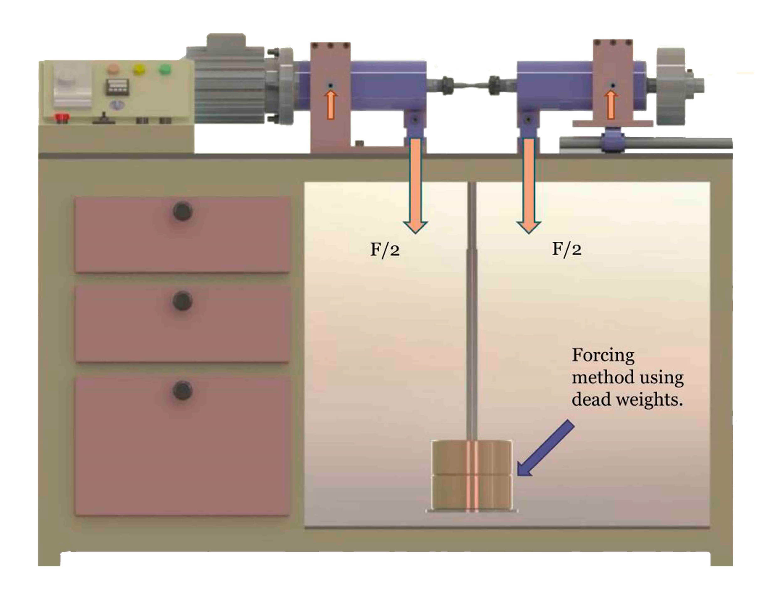
2.3. Experimental Methods

Specimens for microstructure examination were prepared from both the web and the rim regions. For the wheel web, specimens were extracted perpendicular to the wheel radial direction and etched using 2% Nital solution (2% HNO3 in ethanol) to reveal the ferrite–pearlite microstructure. This etchant effectively distinguishes ferrite (light grey) from pearlite (dark lamellar regions), facilitating analysis of phase morphology and grain orientation. For the wheel rim, the specimens were extracted both perpendicular to and parallel to the wheel axis. They were etched using a two-step procedure. First, they were pre-etched with 2% Nital solution to reveal initial grain boundaries. After rinsing with absolute ethanol, the samples were further etched with LePera reagent, a color etchant composed of equal volumes of 10 g/L aqueous sodium metabisulfite and 40 g/L picric acid in ethanol. This etching sequence enabled enhanced phase contrast.
To evaluate the mechanical properties of the wheel, microhardness test was conducted on different longitudinal sections of a wheel rim. Specimens for tensile tests were extracted from two critical regions, as shown in Figure 1b. These include the web region and the rim region, which are subjected to different stress states during service. The tensile tests were performed using an MTS 809 testing machine (MTS Systems Corporation, Eden Prairie, MN, USA) at room temperature, following the GB/T 228.1-2021 standard [61]. For each region (rim and web), three specimens were tested to ensure repeatability. A cross-sectional schematic indicates that rim specimens were taken 15 mm below the tread surface and from a location near the inner surface of the flange. In contrast, web specimens were extracted near the central axis of the wheel plate. These locations were strategically selected to assess variations in microstructure and mechanical response due to the wheel geometry, thermal gradients during manufacturing, and in-service stress distributions. The specimen size is given in Figure 1c.
In the rotating bending fatigue test, a four-point rotating bending fatigue testing method was applied. This method is suitable for evaluating wheel rim fatigue performance under service-simulated conditions. Figure 2 shows a schematic diagram of a four-point rotating bending fatigue testing machine, which is a standard apparatus used to evaluate the fatigue strength and life of materials under controlled bending conditions. Driven by a motor, the cylindrical specimen rotates about its longitudinal axis at a constant speed. Two equal downward forces (F/2) are applied via loading points at a certain distance apart. The force is applied by hanging calibrated dead weights, ensuring constant-magnitude cyclic loading. Because the specimen rotates while the load direction remains fixed, each point on the specimen’s surface experiences tensile and compressive stresses in alternating fashion, producing fully reversed cyclic bending (the stress ratio R = −1). This is ideal for characterizing VHCF behavior. The test induces a rotating bending moment, generating a sinusoidal stress waveform in time. As the surface experiences maximum stress, it is the most probable site for fatigue crack initiation. This setup ensures uniform stress distribution, controlled crack initiation location, and accurate fatigue life measurement, which is directly relevant for assessing material anisotropy, microstructural effects, and hardness gradients.
Figure 3 presents a detailed schematic of a fatigue specimen clamping configuration and the resulting stress distribution—typically used in rotating bending fatigue tests. This type of specimen geometry and fixture is designed to ensure precise loading, controlled stress localization, and reliable fatigue failure initiation. The hourglass-shaped specimen has a shoulder diameter of 12 mm, a minimum diameter of 4 mm at the central gauge section, and a fillet radius of 36 mm, creating a well-defined stress concentration zone with a stress concentration factor of 1.24, which ensures fatigue cracks initiate and propagate in a predictable location, maximizing result consistency and minimizing scatter in fatigue life data. Away from transition zones, the stress field in the gauge section is effectively uniaxial and bending-dominated, ideal for fatigue S–N curve generation. In this study, fatigue specimens were extracted, perpendicular to the wheel radial direction, from the wheel rim region (in the middle of the height H and axis ~30 mm from the tread edge). Two batches, containing 20 and 27 fatigue specimens, respectively, were tested to improve reproducibility. To assess material consistency across different wheels, two batches of fatigue specimens were extracted separately from two forged and heat-treated wheels.

3. Results

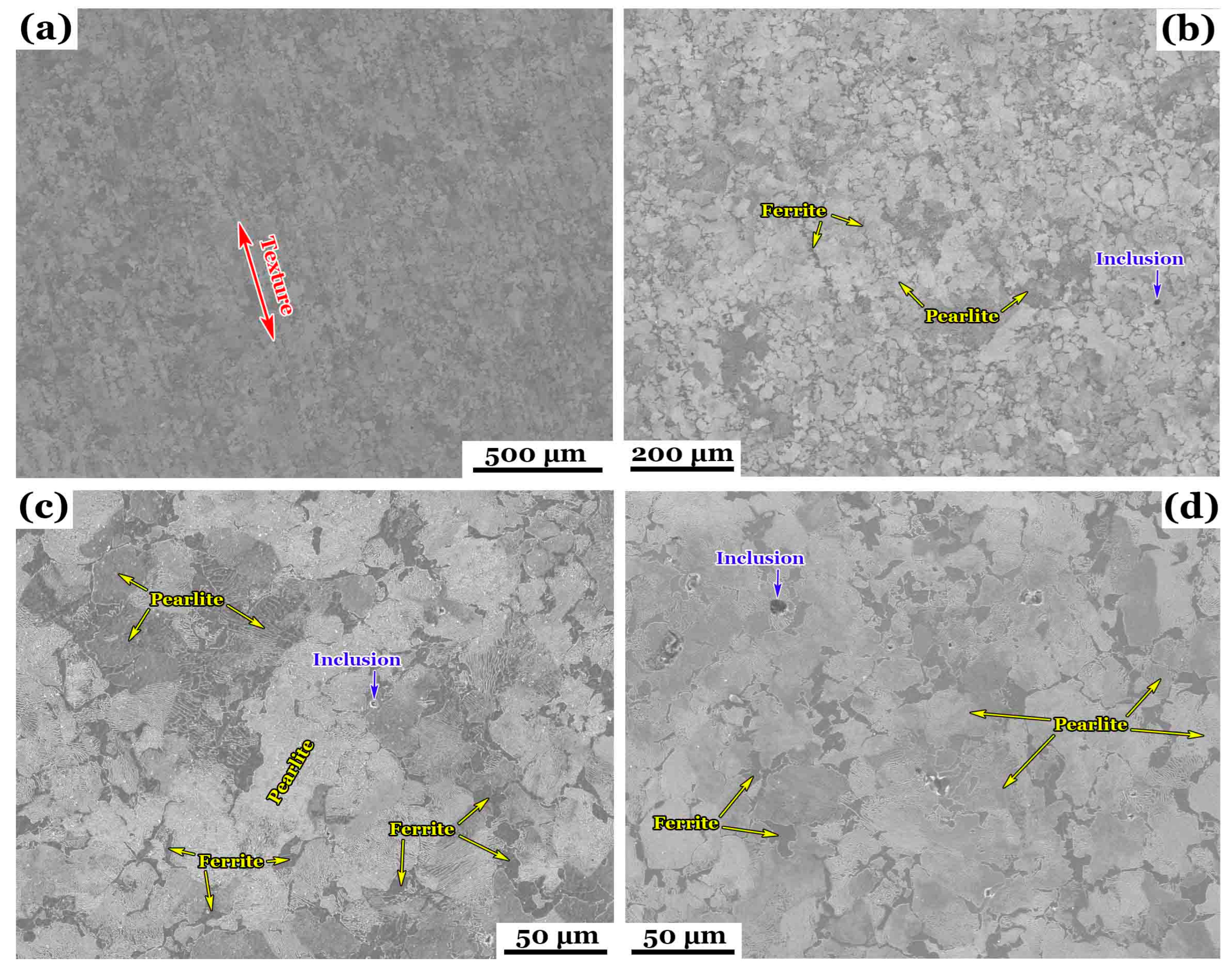
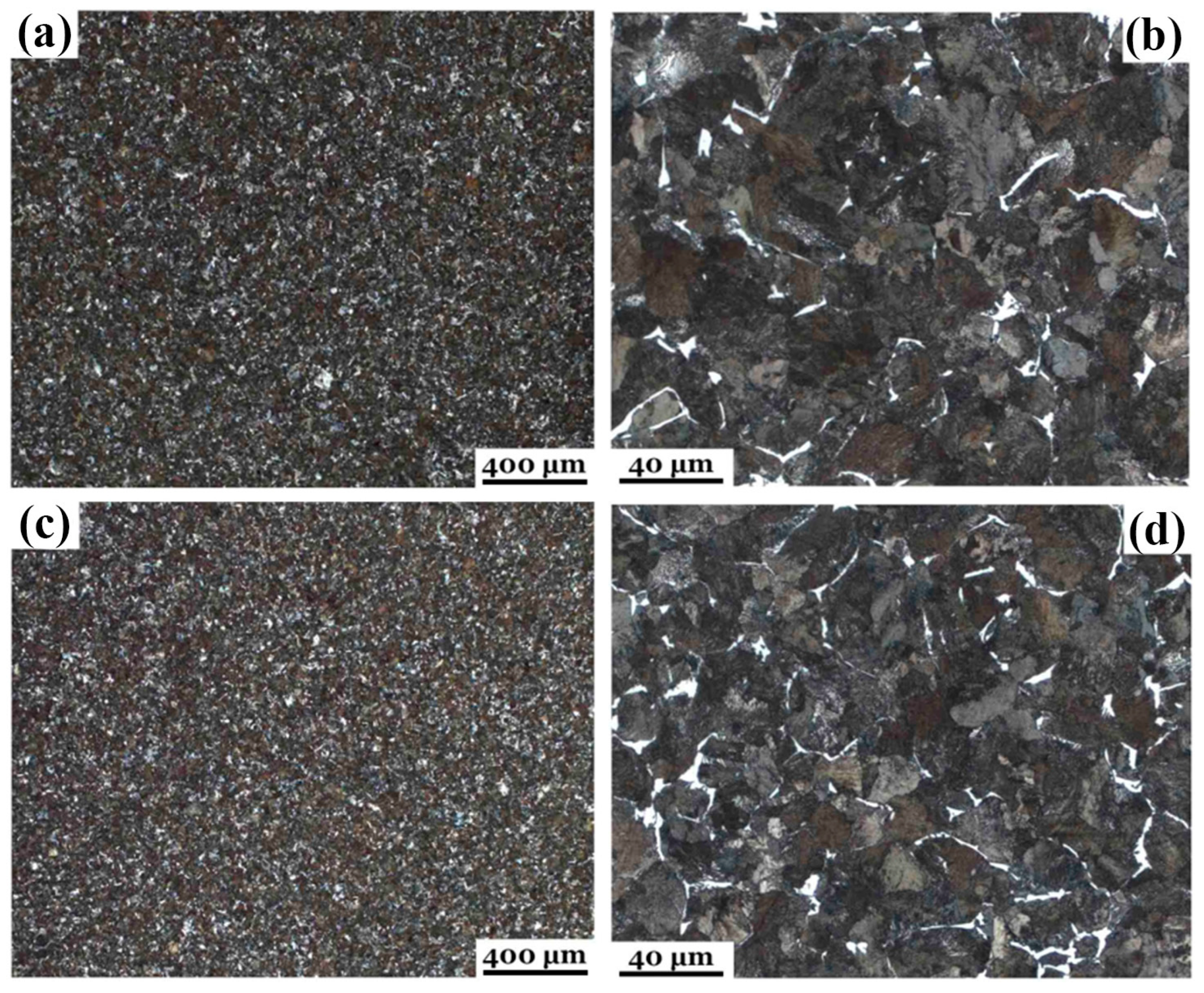
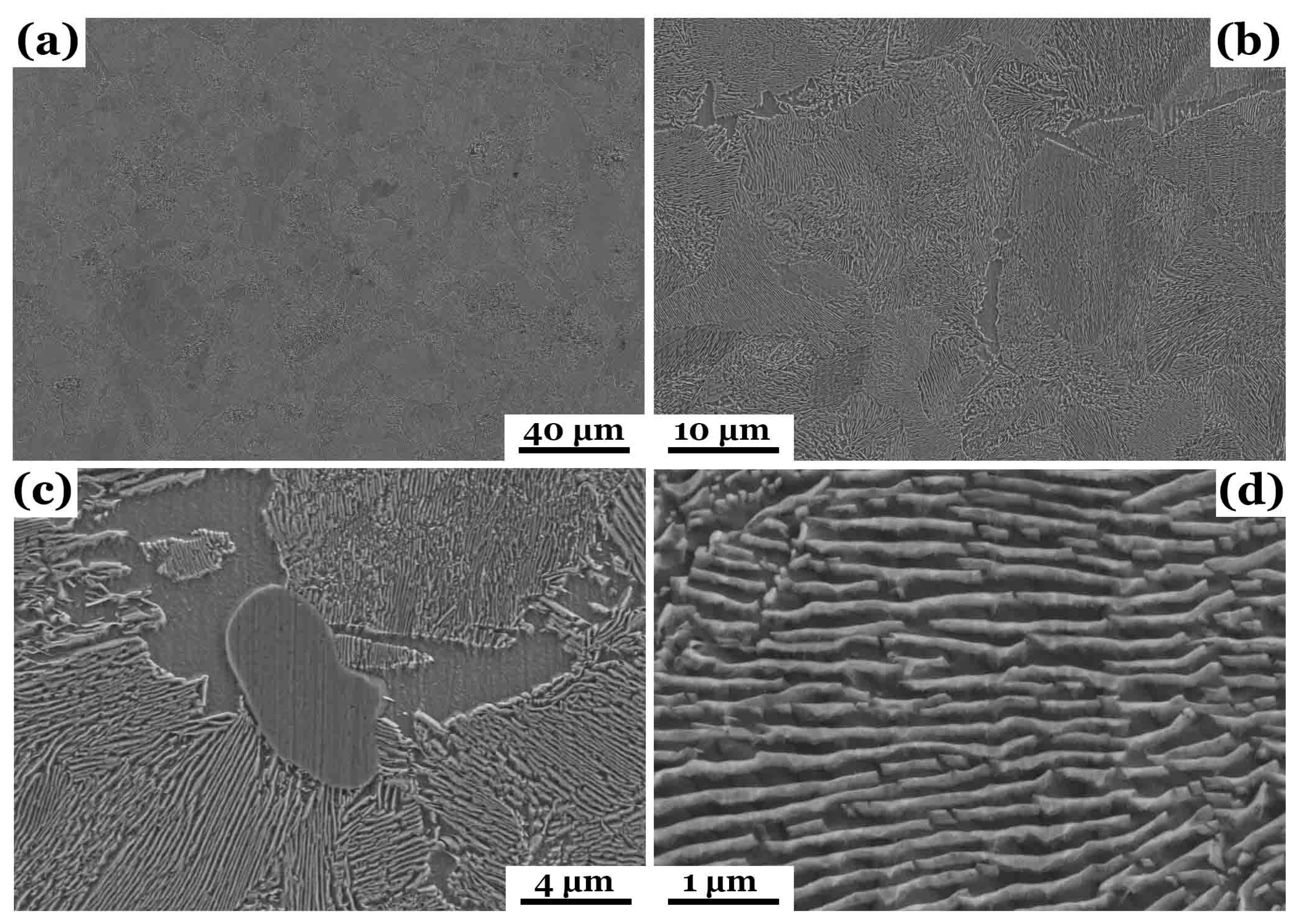
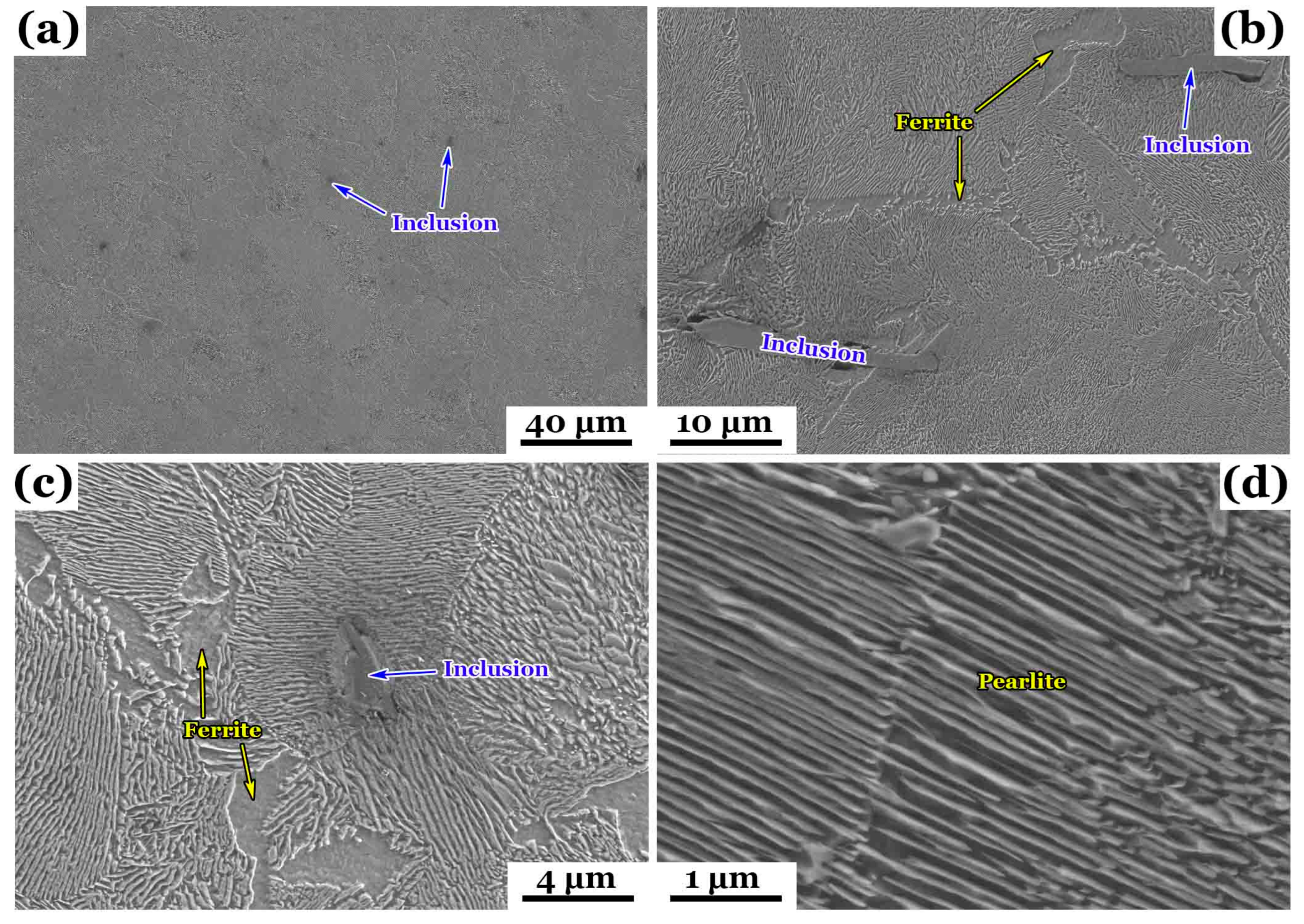
3.1. Microstructure Observations
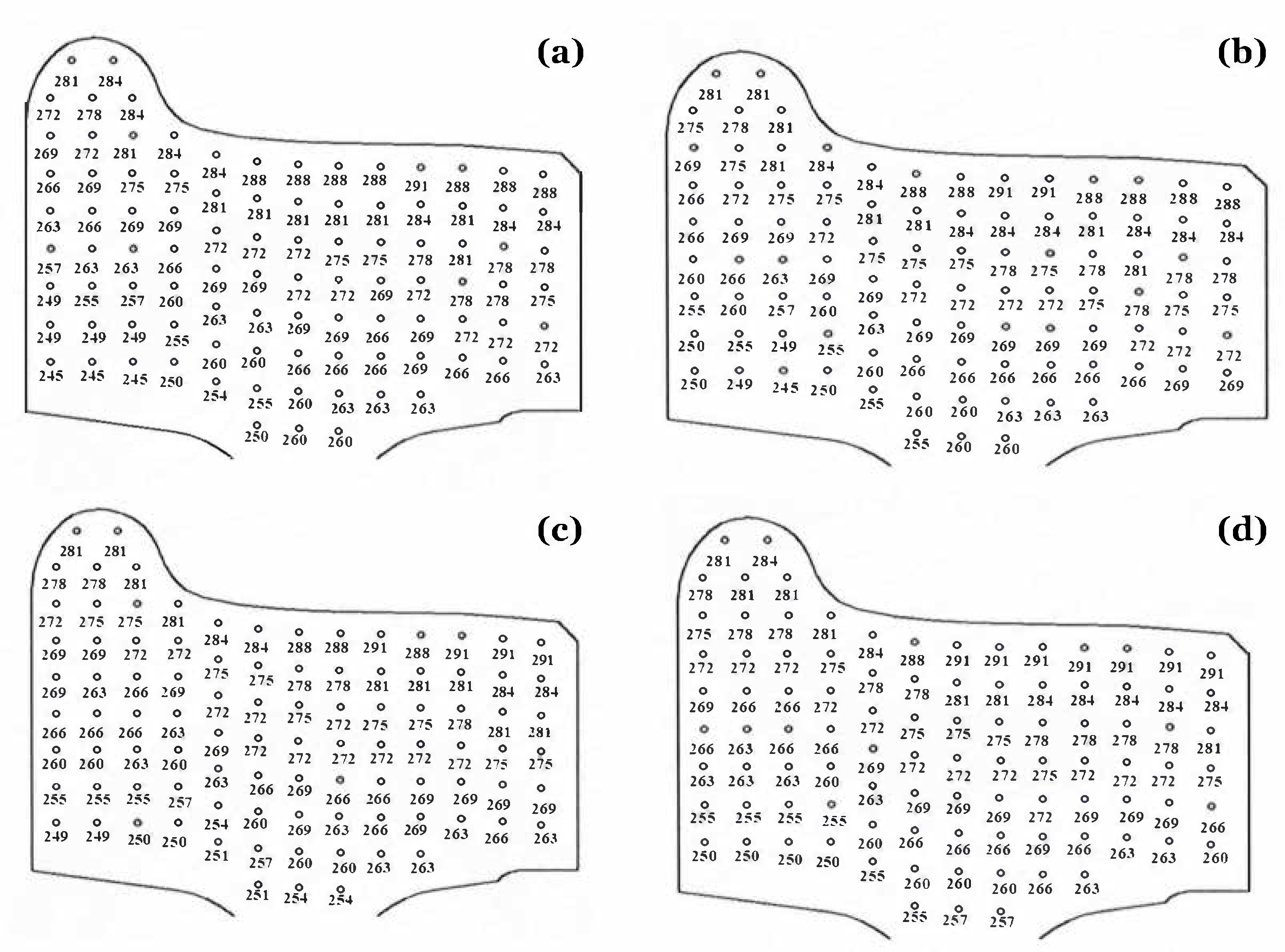
The cross-sectional microstructure of the wheel web perpendicular to the wheel radial direction was examined optically under different magnifications and locations (Figure 4). Figure 4a (500 μm) shows elongated ferrite–pearlite grains aligned with the forging direction, i.e., the radial direction of the wheel. This elongated microstructure was developed during hot forging and retained due to the absence of post-forging heat treatments in the web. Upon cooling, austenite transformed into ferrite and pearlite. Pearlite formation likely initiated along austenite grain boundaries, which can be identified more clearly in Figure 4b–d under higher magnifications, i.e., 200–50 μm scale, showing ferrite (α-Fe) and pearlite colonies marked by the yellow arrows. Ferrite appears as light-grey equiaxed regions, while pearlite forms darker lamellar structures from eutectoid transformation. Based on optical contrast, the ferrite phase fraction is estimated to be slightly above 50%. The grain length often exceeds 25–30 µm, with visible alignment.
This observation results from a transformation from austenite into ferrite and pearlite during cooling when pearlite formation initiated along austenite grain boundaries. The dominant ferrite–pearlite microstructure offers a balance between strength and ductility, ideally suitable for manufacturing high-speed train wheels. Pearlite, with its lamellar cementite and ferrite, is harder and tends to concentrate on stress, making it a preferential site for fatigue crack initiation, especially under HCF conditions. Ferrite–pearlite interfaces act as mechanical heterogeneities, localizing microplastic strain. This promotes slip incompatibility and persistent slip band (PSB) formation, which can evolve into microcracks [19,21,24]. Due to probable insufficient secondary refining, inclusions (marked in blue) are present in various locations and may represent oxides, sulfides, or non-metallic particles introduced during solidification. They serve as stress concentrators, potentially reducing fatigue resistance and ductility. Crack initiation often begins at the inclusion–matrix interface, especially under rotating bending fatigue conditions, which corresponds to the case investigated in this study.
Figure 5 shows the metallographs of wheel rim both perpendicular to and parallel with the wheel radial direction under different magnifications and locations. Figure 5a illustrates typical microstructural features of both fine-grained and equiaxed microstructure under low magnifications. Bright areas represent pearlite colonies, while dark regions correspond to ferrite (Figure 5b,d). No elongated grains are apparent, indicating equiaxed grains. In Figure 5c,d, which show the metallographs of wheel rim parallel to the wheel radial direction under different magnifications and locations, the characteristics of equiaxed grains can also be identified. The rim microstructure shows more refined grains with an estimated pearlite phase fraction of approximately 60%. Grain sizes are uniformly distributed with diameters typically in the 10–15 µm range. The uniform ferrite–pearlite microstructure reflects effective thermo-mechanical processing control, which usually achieves a favorable combination of strength and ductility and isotropic mechanical behavior. This is typically used in manufacturing high-speed train wheel rims, which can prevent the formation of bainite or martensite, ensuring ductility is preserved while maintaining adequate hardness.
In terms of fatigue performance, such a dual-phase structure enhances crack initiation resistance due to ferrite’s plastic accommodation and retards crack propagation through tortuous ferrite–pearlite interfaces, making it well-suited for high-cycle rolling contact fatigue conditions in high-speed rail wheel rims [21,24,26]. Rolling contact fatigue from wheel–rail interaction is the dominant failure mode, although thermal fatigue and cyclic bending or tension also contribute. Since no obvious defects or inclusions can be identified in the figures, crack initiation likely occurs at ferrite–pearlite interfaces due to mismatch in hardness. Cracks may preferentially propagate through pearlite, particularly when lamellae are coarse or misaligned with the loading direction [21,24].
As shown in Figure 4 and Figure 5, the web and rim exhibit different grain morphologies under optical microscopy. The web region (Figure 4) displays elongated ferrite–pearlite grains aligned along the radial direction due to forging, whereas the rim (Figure 5) reveals fine, equiaxed grains resulting from surface quenching and tempering. The etching response is also more homogeneous in the rim, indicating uniform phase distribution and higher transformation stability.
Figure 6 and Figure 7 provide higher-resolution SEM images detailing the microstructural constituents. Figure 6 shows the SEM images of wheel rim perpendicular to the wheel axis under different magnifications and locations. Similarly, Figure 7 shows the SEM images of wheel rim parallel to the wheel axis under different magnifications and locations. Both Figure 6a and Figure 7a show a ferrite–pearlite matrix with clearly defined pearlite colonies. The colony boundaries are visible, and their size appears relatively small and uniformly distributed, indicating controlled cooling and fine transformation structures. Inclusions, marked in blue, can be identified in Figure 7a. Some discontinuities are visible in Figure 6b, which potentially compromises the mechanical performance. In Figure 6c and Figure 7c, a well-developed lamellar pearlite microstructure is evident, with alternating ferrite (dark area) and cementite (bright area) lamellae. The morphology of pearlite colonies and cementite alignment indicates that the steel underwent eutectoid transformation from austenite during controlled air cooling or normalizing. The inclusion can be clearly identified in both the figures, which creates a stress concentration site and probably becomes an origin for crack initiation during service. Figure 6d and Figure 7d are taken under a high magnification, i.e., 1 μm scale. The bonelike pearlite lamella appears uniform, parallel, and closely spaced, which is favorable for mechanical performance, but arrow interlamellar spacing enhances strength and fatigue resistance may compromise ductility under low-cycle fatigue. In Figure 7d, narrower interlamellar spacing is visible due to a different structure orientation, compared with Figure 6d. The ferrite–pearlite interface introduces mechanical heterogeneity, potentially leading to PSB formation and early crack nucleation [19,21]. The longitudinal (axial) orientation of pearlite lamellae increases anisotropy in fatigue resistance [24]. Thus, fatigue cracks may grow faster parallel to lamella but are deflected or blunted by lamella interfaces when they propagate perpendicularly.
While optical microscopy (Figure 5) shows a refined ferrite–pearlite microstructure in the rim, SEM images (Figure 6 and Figure 7) provide further insight into lamellar spacing, interface morphology, and grain boundary definition. The SEM observations confirm a more compact pearlite colony structure with narrow interlamellar spacing and smooth ferrite–cementite boundaries—features that are conducive to higher hardness and fatigue strength in the rim.
Compared to the web region (Figure 4), the wheel rim exhibits a more refined and equiaxed ferrite–pearlite microstructure (Figure 5, Figure 6 and Figure 7), reflecting the effect of surface quenching and subsequent tempering. In contrast, the web retains elongated grains aligned along the forging direction, indicating minimal post-forging heat treatment. This results in higher hardness and strength in the rim, with improved isotropy and fatigue resistance, while the web maintains better ductility but also stronger elongated microstructure. These differences underscore the region-dependent nature of thermo-mechanical processing in railway wheels.

3.2. Microhardness

Based on Figure 8, Brinell hardness (HBW) distributions across different longitudinal sections of a wheel rim reveal both the mechanical consistency and process-induced variation in the wheel rim—critical for understanding its in-service performance, especially under fatigue loading, rolling contact, and thermal cycling. The hardness distribution reflects a ferrite–pearlite microstructure, as confirmed in the previous figures. Higher hardness zones (outer rim) are most likely dominated by fine pearlite with narrow lamellar spacing and beneficial for wear resistance and rolling contact fatigue resistance. Lower hardness zones (inner rim) have higher ferrite fraction with larger grain sizes. This part provides ductility and toughness relatively, improving resistance to impact and thermal fatigue. Both higher hardness zones and lower hardness zones play important roles in enhancing damage tolerance. The hard outer layer resists wear and surface fatigue, while the softer core absorbs plastic deformation and retards crack growth.
Each subfigure of Figure 8 represents a different longitudinal section of the wheel rim. The measured hardness values range from approximately 245 HBW to 291 HBW. A general trend can be concluded quantitively on all the sections; the outer rim surface (tread region) consistently exhibits higher hardness (~278–291 HBW), while the inner regions (closer to the hub or web) show slightly lower hardness (~245–260 HBW). Figure 8a shows a smooth gradient, suggesting uniform cooling and transformation with no abrupt transitions. In Figure 8b, hardness is slightly higher overall than in Figure 8a, especially in the outer shoulder and central rim zone, indicating more efficient cooling in this section. Figure 8c reveals slightly lower hardness at the base (~251–254 HBW) compared to other sections, which might pose concern for contact fatigue or bending stresses. Figure 8d gives the highest average hardness across all zones (~275–291 HBW). This section likely has the best fatigue and wear resistance but may also be more brittle if pearlite is dominant and not tempered.

3.3. Tensile Properties

Table 2 shows the tensile properties of specimens extracted from the wheel rim and web. For the wheel rim, the measured tensile strength is 929 MPa, well within the required range of 860–980 MPa. The measured yield strength goes to 602 MPa, comfortably above the required 540 MPa. The elongation after fracture is 17.0%, exceeding the 13% threshold and indicating good ductility. The reduction in area comes to 46%, suggesting plastic deformability and damage tolerance. These results confirm the presence of ductile ferrite regions and low inclusion content, despite some inclusion alignment observed in SEM images. Similarly, for the wheel web, the measured tensile strength, 779 MPa, also falls within the acceptable range of 740–860 MPa. The measured elongation, 21.0%, exceeds the 16% threshold and the reduction in area is 42%. Since the web does not experience direct wheel–rail contact, its design prioritizes toughness and ductility over strength. The wheel rim demonstrates high strength and fatigue resistance due to its fine pearlitic microstructure, while the wheel web has relatively lower strength, as this region is designed to absorb shock and flex under service loads. This complementary mechanical behavior is crucial for ensuring long-term safety and durability of high-speed train wheels.

3.4. Low-Cycle and High-Cycle Fatigue

Figure 9 presents the S–N data for two batches of specimens tested under rotating bending fatigue conditions. From Figure 9a, the overall fatigue behavior of both specimen batches can be compared. In 104 and 106 cycle regime, failure is observed under stress amplitudes ranging from ~400 to 470 MPa. It generally shows the classical S–N downward trend, which is consistent with findings reported in related studies. At or below ~430 MPa, multiple specimens reached over 107 cycles without failure, indicating a fatigue endurance limit in this material. The runout plateau suggests a safe stress amplitude threshold for infinite life design. The two batches (red vs. blue), largely overlapped but slightly scattered, are observed, likely due to microstructural variations such as grain size and inclusion content. The limited scatter suggests good uniformity in microstructure and mechanical performance between the two wheels.
Figure 9b shows a clearer picture of the S–N data by adjusting the display ranges of the coordinate axes. Red and blue hollow dots show tighter clustering in the ~460–480 MPa range, with failure occurring between 5 × 10⁴ and 5 × 10⁵ cycles. Fatigue scatter is more pronounced as stress decreases, which is probably attributed to minor microstructural fluctuations and machining variability. Importantly, no systematic difference in fatigue behavior was observed between the two batches. At ~425 MPa, most specimens fail around 106 cycles, while one survives 107 cycles. At or below ~400 MPa, most specimens survive 107 cycles. This highlights the transition zone near the fatigue limit, where minor variations in surface condition, inclusions, or microstructure can markedly influence fatigue life. These results are compatible with the data in Table 2. The fatigue limit can be estimated at around a half of the tensile strength by considering the materials of both the wheel rim and the wheel web, which is typical for ferrite–pearlite steels.
To enhance the interpretability of the S–N results, trend lines based on a Basquin-type power-law model (S = ANb) were fitted to the fatigue data for both batches. As shown in Figure 9, these fitted curves capture the typical fatigue behavior, with failures occurring between 104 and 106 cycles under stress amplitudes of 430–470 MPa, and runout behavior observed at or below ~410 MPa. The overlap and consistency between the two batches further validate the repeatability of the fatigue performance. The fitted S–N curves help visualize the endurance limit region more clearly.

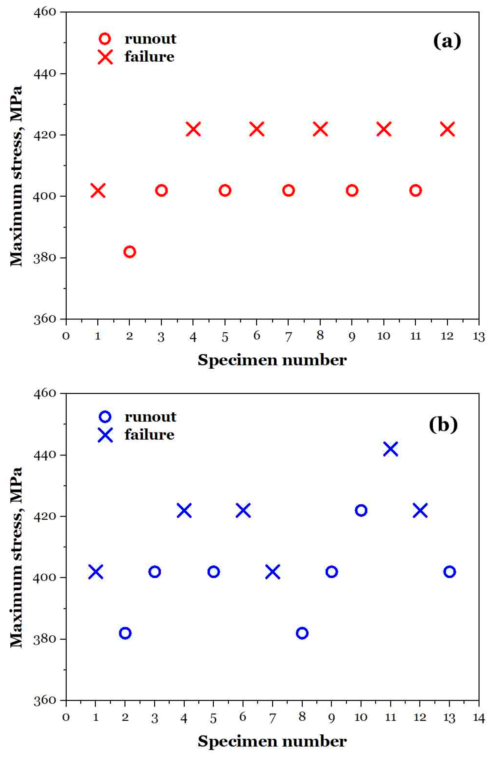
3.5. Estimating Fatigue Limit by Staircases

The staircase (up-and-down) method was adopted in this study to estimate the fatigue limit for its simplicity, low specimen requirement, and suitability for materials exhibiting clear runout behavior. While alternative statistical approaches such as the probit method or maximum likelihood estimation (MLE) may offer higher precision, they often require a larger sample size and more sophisticated data modeling. Given the practical constraints of wheel steel testing and the need to evaluate batch variability, the staircase method provides a reliable and standardized estimation of the endurance limit, especially for preliminary assessments under rotating bending conditions.
Figure 10 presents fatigue testing results obtained using the staircase method, also called up-and-down method, a statistical method for estimating the fatigue limit of a material. This method usually incrementally increases or decreases stress based on the previous specimen’s outcome. If a specimen fails, the next one is tested at a lower stress level. If a specimen survives (runout), the next one is tested at a higher stress level. This creates a “stair-step” pattern from which the mean fatigue limit and standard deviation can be statistically estimated. The method and presentation offer insight into statistical fatigue strength at a fixed life level, commonly around 106 or 107 cycles. Figure 10a shows the red batch with the stress range of ~380–430 MPa. Repeated failures occur between 420 and 430 MPa. Runouts mostly occur around 400 MPa. The transition zone between runout and failure is ~410–420 MPa. Thus, the fatigue limit for this batch can be estimated as 412 ± 4 MPa. For the blue batch, following the same steps, the stress ranges from 380 MPa to 440 MPa. Clear alternation between failure and runout occurs near ~400–420 MPa, indicating the threshold zone. Failure cluster goes near ~430–440 MPa. Runouts occur between ~390 and 410 MPa. So, the estimated fatigue limit for this blue batch is 415 ± 5 MPa, consistent with the red batch. Based on the fatigue limits of both batches, the overall fatigue limit is estimated as 414 ± 5 MPa, considering the average value and uncertainty range.
The consistent fatigue limit across batches from two different wheels validates the reliability of processing and microstructural control. This fatigue limit can be used as the design allowable stress amplitude for wheel materials under infinite-life (very-high-cycle) loading conditions. The result confirms that, below ~410 MPa, the material can safely survive 107 cycles without failure—critical for long-life applications such as high-speed train wheels.
The fatigue limit observed in this study is consistent with previously reported values for pearlitic wheel steels subjected to surface quenching, which typically range from 400 to 450 MPa under rotating bending conditions [24,26]. Compared to EA4T steels studied in [27,28], our samples demonstrate slightly higher ductility but comparable tensile strength, reflecting effective microstructural control through forging and heat treatment. The observed gradient in hardness across the rim thickness also matches trends reported in other studies on forged monobloc wheels [30], suggesting that our process yields typical and reliable mechanical performance for high-speed rail service.

3.6. Engineering Implications and Limitations

The findings of this study offer practical guidance for optimizing the structural design and heat treatment processes of high-speed train wheels. The microstructural characterization reveals that the rim region, subjected to surface quenching and tempering, achieves a refined ferrite–pearlite microstructure with high hardness and strength, making it particularly well-suited for resisting rolling contact fatigue and wear. The hardness gradient observed near the tread surface offers practical guidance for optimizing surface quenching depth—ensuring sufficient residual strength while avoiding excessive brittleness. Meanwhile, the web retains a forged microstructure and exhibits lower strength but higher ductility, suggesting a load-buffering role under dynamic bending and axial stress, which could be tailored through localized tempering or annealing strategies. This functional differentiation underscores the importance of tailoring processing conditions based on regional service demands. From an engineering perspective, adopting functionally graded heat treatment strategies can help achieve an optimal balance between surface durability and structural compliance. The observed fatigue limit of ~410 MPa for the rim under rotating bending condition provides a reference stress threshold for infinite-life design, contributing to the safe service life extension of high-speed train wheels under high-cycle loading.
However, we notice that some limitations of this study are still there, leaving more space to improve in the future work. The current rotating bending tests were limited to 107 cycles, but the actual service life of high-speed train wheels can reach beyond 108 cycles. In addition, rotating bending fatigue tests were performed only on rim specimens; the comparative mechanical properties of the web suggest that it may exhibit different fatigue behavior. The web’s lower tensile strength (779 MPa) and higher elongation (21%) imply enhanced ductility but potentially lower fatigue strength, especially under bending or combined loads. Another limitation of this study is the absence of fracture surface analysis. Without SEM fractography, confirmation of crack initiation sites or propagation paths is prevented, especially in distinguishing surface-initiated from subsurface failures. Future work will include fatigue testing on the web, VHCF extension via ultrasonic loading, and SEM fractographic and XRD analysis to clarify failure mechanisms and phase composition.

4. Conclusions

This study provides an integrated comparison of the microstructure and mechanical behavior between the wheel rim and web, offering practical insight into process–structure–property relations in critical railway components. The rim, subjected to surface quenching, exhibits a fine-grained, equiaxed ferrite–pearlite microstructure with high hardness (245–291 HBW) and tensile strength (929 MPa), ensuring excellent resistance to rolling contact fatigue and wear. Its isotropic behavior under rotating bending fatigue, with a fatigue limit of 414 ± 5 MPa, highlights the effectiveness of heat treatment in balancing strength and ductility. In contrast, the web retains a forged microstructure with elongated grains, lower strength (779 MPa), and higher ductility (21% elongation), making it suitable for absorbing dynamic loads and resisting crack propagation. However, its pronounced microstructure and potential for inclusion-induced stress concentrations indicate room for improvement through tailored heat treatments to optimize mechanical homogeneity.
The dual-phase structure of the rim enhances crack propagation resistance via tortuous interfaces, while the web’s ductility mitigates risks from bending stress. These findings underscore the importance of gradient material design in wheel engineering, where the rim prioritizes surface durability and the web emphasizes structural flexibility. Although the ferrite–pearlite system is well established, our findings highlight how process-induced gradients across the wheel cross-section can be quantified and linked to fatigue resistance, thus informing functionally graded material strategies in railway applications. Overall, this research provides a foundational framework for enhancing wheel reliability through microstructural control and targeted heat treatments, supporting the safety and longevity of high-speed rail systems.

Author Contributions

Conceptualization, H.S. (Huajian Song) and H.S. (Hang Su); methodology, H.S. (Huajian Song), C.G. and Y.Z.; validation, T.F.; formal analysis, J.W.; investigation, C.G.; resources, C.G. and Y.Z.; data curation, T.F. and J.W.; writing—original draft preparation, H.S. (Huajian Song) and H.S. (Hang Su); writing—review and editing, H.S. (Hang Su); visualization, C.G.; supervision, C.G.; project administration, C.G.; funding acquisition, C.G. and T.F. All authors have read and agreed to the published version of the manuscript.

Funding

This research received no external funding.

Data Availability Statement

Data will be made available on reasonable request.

Acknowledgments

C.G. and Y.Z. gratefully acknowledge the Underground Engineering Technology Laboratory for providing the necessary equipment for this study.

Conflicts of Interest

Author Tao Fan was employed by Heilongjiang Zhongbei Post and Telecommunications Con-struction and Development Company. The remaining authors declare that the research was conducted in the absence of any commercial or financial relationships that could be construed as a potential conflict of interest.

References

  1. Leboeuf, M. High Speed Rail—Fast Track to Sustainable Mobility; International Union of Railways: Paris, France, 2018. [Google Scholar]
  2. High-Speed Rail: Definition, History, Technology, Development, & Facts. Available online: https://www.britannica.com/technology/high-speed-rail (accessed on 6 April 2025).
  3. Glossary: High-Speed Rail. Available online: https://ec.europa.eu/eurostat/statistics-explained/index.php?title=Glossary:High-speed_rail (accessed on 6 April 2025).
  4. High-Speed Rail. Available online: https://en.wikipedia.org/wiki/High-speed_rail (accessed on 6 April 2025).
  5. Ollivier, G.; Bullock, R.; Jin, Y.; Zhou, N. High-Speed Railways in China: A Look at Traffic; World bank: Washington, DC, USA, 2014. [Google Scholar]
  6. TB 10621-2014; Code for Design of High Speed Railway. National Railway Administration: Beijing, China, 2014. (In Chinese)
  7. The State Council Information Office of the People’s Republic of China. Development of China’s Transport; State Council Information Office: Beijing, China, 2016. (In Chinese)
  8. International Union of Railways. High-Speed Lines in the World; International Union of Railways: Paris, France, 2024. [Google Scholar]
  9. TB/T 2817-2018; Solid Forged and Rolled Wheels for Railway Wagon Applications. National Railway Administration: Beijing, China, 2018. (In Chinese)
  10. EN 13262; Railway applications—Wheelsets and Bogies—Wheels—Product Requirements. CEN: Brussels, Belgium, 2020.
  11. TB/T 3469-2016; Solid Forged and Rolled Wheels for Locomotive. National Railway Administration: Beijing, China, 2016. (In Chinese)
  12. EN 13979-1; Railway applications—Wheelsets and bogies—Monobloc Wheels—Technical approval procedure—Part 1: Forged and Rolled Wheels. CEN: Brussels, Belgium, 2023.
  13. Meyers, M.A.; Chawla, K.K. Mechanical Behavior of Materials, 2nd ed.; Cambridge University Press: Cambridge, UK, 2009. [Google Scholar]
  14. Dowling, N.E. Mechanical Behavior of Materials: Engineering Methods for Deformation, Fracture, and Fatigue, 4th ed.; Pearson: Boston, MA, USA, 2013. [Google Scholar]
  15. Hertzberg, R.W.; Vinci, R.P.; Hertzberg, J.L. Deformation and Fracture Mechanics of Engineering Materials, 6th ed.; Wiley: Oxford, UK, 2020. [Google Scholar]
  16. Pan, X.; Qian, G.; Hong, Y. Nanograin formation in dimple ridges due to local severe-plastic-deformation during ductile fracture. Scr. Mater. 2021, 194, 11363. [Google Scholar] [CrossRef]
  17. Xu, S.; Pan, S.; Li, Z.; Li, S.; He, X.; Pan, X. Anisotropic tensile behavior and fracture characteristics of an additively manufactured nickel alloy without and with a heat treatment of solution aging. Mater. Sci. Eng. A 2025, 927, 148015. [Google Scholar] [CrossRef]
  18. Suresh, S. Fatigue of Materials, 2nd ed.; Cambridge University Press: Cambridge, UK, 1998. [Google Scholar]
  19. Murakami, Y. Metal Fatigue: Effect of Small Defects and Nonmetallic Inclusions; Elsevier: Oxford, UK, 2002. [Google Scholar]
  20. Schijve, J. Fatigue of Structures and Materials, 2nd ed.; Springer: Dordrecht, Germany, 2009. [Google Scholar]
  21. Pan, X.; Su, H.; Sun, C.; Hong, Y. The behavior of crack initiation and early growth in high-cycle and very-high-cycle fatigue regimes for a titanium alloy. Int. J. Fatigue 2018, 115, 67–78. [Google Scholar] [CrossRef]
  22. Pan, X.; Hong, Y. High-cycle and very-high-cycle fatigue behaviour of a titanium alloy with equiaxed microstructure under different mean stresses. Fatigue Fract. Eng. Mater. Struct. 2019, 42, 1950–1964. [Google Scholar] [CrossRef]
  23. Sun, C.; Song, Q.; Zhou, L.; Pan, X. Characteristic of interior crack initiation and early growth for high cycle and very high cycle fatigue of a martensitic stainless steel. Mater. Sci. Eng. A 2019, 758, 112–120. [Google Scholar] [CrossRef]
  24. Chang, Y.; Zheng, L.; Pan, X.; Hong, Y. Further investigation on microstructure refinement of internal crack initiation region in VHCF regime of high-strength steels. Frat. Ed Integrità Strutturale 2019, 13, 1–11. [Google Scholar] [CrossRef]
  25. Chang, Y.; Pan, X.; Zheng, L.; Hong, Y. Microstructure refinement and grain size distribution in crack initiation region of very-high-cycle fatigue regime for high-strength alloys. Int. J. Fatigue 2020, 134, 105473. [Google Scholar] [CrossRef]
  26. Pan, X.; Xu, S.; Qian, G.; Nikitin, A.; Shanyavskiy, A.; Palin-Luc, T.; Hong, Y. The mechanism of internal fatigue-crack initiation and early growth in a titanium alloy with lamellar and equiaxed microstructure. Mater. Sci. Eng. A 2020, 798, 140110. [Google Scholar] [CrossRef]
  27. Liu, L.; Ma, Y.; Liu, S.; Wang, S. The fatigue behaviors of a medium-carbon pearlitic wheel-steel with elongated sulfides in high-cycle and very-high-cycle regimes. Materials 2021, 14, 4318. [Google Scholar] [CrossRef] [PubMed]
  28. Cong, T.; Qian, G.; Zhang, G.; Wu, S.; Pan, X.; Du, L.; Liu, X. Effects of inclusion size and stress ratio on the very-high-cycle fatigue behavior of pearlitic steel. Int. J. Fatigue 2021, 142, 105958. [Google Scholar] [CrossRef]
  29. Zhou, H.; Suzuki, Y.; Kinefuchi, M.; Shibanuma, K. Applicability of the multiscale model for predicting fatigue strength to short and long crack problems. ISIJ Int. 2022, 62, 2126–2131. [Google Scholar] [CrossRef]
  30. Zhou, H.; Liu, Z.; Kinefuchi, M.; Shibanuma, K. Multiscale modelling strategy for predicting fatigue lives and limits of steels based on a generalised evaluation method of grain boundaries effects. Int. J. Fatigue 2022, 158, 106749. [Google Scholar] [CrossRef]
  31. Zhou, Y.; Sun, J.; Pan, X.; Qian, G.; Hong, Y. Microstructure evolution and very-high-cycle fatigue crack initiation behavior of a structural steel with two loading intermittence modes. Int. J. Fatigue 2022, 161, 106904. [Google Scholar] [CrossRef]
  32. Chen, Z.; Bao, H.; Dai, Y.; Liu, Y. Numerical prediction based on XFEM for mixed-mode crack growth path and fatigue life under cyclic overload. Int. J. Fatigue 2022, 162, 106943. [Google Scholar] [CrossRef]
  33. Chen, Z.; Dai, Y.; Liu, Y. Numerical study on high-cycle fatigue crack growth of sinusoidal interface based on cyclic cohesive zone model. Int. J. Fatigue 2023, 174, 107748. [Google Scholar] [CrossRef]
  34. Chen, Z.; Dai, Y.; Liu, Y. Life prediction of corrosion-fatigue based on a new crack growth rate model with damage and the extended finite element method. Eng. Fract. Mech. 2023, 289, 109445. [Google Scholar] [CrossRef]
  35. Zhou, H.; Suzuki, Y.; Kinefuchi, M.; Schmauder, S.; Dogahe, K.; Shibanuma, K. Bridging strategy between microscopic and macroscopic crack growth simulations to predict fatigue strength of steels. Int. J. Fatigue 2023, 168, 107386. [Google Scholar] [CrossRef]
  36. Zhou, H.; Liu, Z.; Kikuchi, S.; Shibanuma, K. Analysis of fatigue performance of austenitic stainless steels with bimodal harmonic structures based on multiscale model simulations. Mater. Des. 2023, 226, 111657. [Google Scholar] [CrossRef]
  37. Hong, Y.; Hu, Y.; Zhao, A. Effects of loading frequency on fatigue behavior of metallic materials—A literature review. Fatigue Fract. Eng. Mater. Struct. 2023, 46, 3077–3098. [Google Scholar] [CrossRef]
  38. Pan, X.; Su, H.; Liu, X.; Hong, Y. Multi-scale fatigue failure features of titanium alloys with equiaxed or bimodal microstructures from low-cycle to very-high-cycle loading numbers. Mater. Sci. Eng. A 2024, 890, 145906. [Google Scholar] [CrossRef]
  39. Pan, X.; Xu, S.; Nikitin, A.; Shanyavskiy, A.; Palin-Luc, T.; Hong, Y. Crack initiation induced nanograins and facets of a titanium alloy with lamellar and equiaxed microstructure in very-high-cycle fatigue. Mater. Lett. 2024, 357, 135769. [Google Scholar] [CrossRef]
  40. Chen, Z.; Dai, Y.; Liu, Y. Crack propagation simulation and overload fatigue life prediction via enhanced physics-informed neural networks. Int. J. Fatigue 2024, 186, 108382. [Google Scholar] [CrossRef]
  41. Chen, Z.; Dai, Y.; Liu, Y. Structural fatigue crack propagation simulation and life prediction based on improved XFEM-VCCT. Eng. Fract. Mech. 2024, 310, 110519. [Google Scholar] [CrossRef]
  42. Romano, L.; Maglio, M.; Bruni, S. Transient wheel-rail rolling contact theories. Tribol. Int. 2023, 186, 108600. [Google Scholar] [CrossRef]
  43. Shao, Z.; Zou, Q.; Zhu, Y.; Zhang, P.; Wang, B.; Xu, Z.; Gu, X.; Wang, Q.; Zhang, Z. Effect of alloy elements on the rolling contact fatigue performance of wheel steel. Mater. Sci. Eng. A 2024, 913, 147085. [Google Scholar] [CrossRef]
  44. Bai, Z.; Zhou, J.; Lin, Y.; Li, J.; Ma, C.; Shen, M. Effects of intermittent airflow on rolling contact damage characteristics of wheel steels in a low-temperature environment: Airflow humidity. Wear 2025, 572–573, 206025. [Google Scholar] [CrossRef]
  45. Li, Z.; Han, J.; Yang, Z.; Li, W. Analyzing the mechanisms of thermal fatigue and phase change of steel used in brake discs. Eng. Fail. Anal. 2015, 57, 202–218. [Google Scholar] [CrossRef]
  46. Hong, H.; Kim, M.; Lee, H.; Jeong, N.; Moon, H.; Lee, E.; Kim, H.; Suh, M.; Chung, J.; Lee, J. The thermo-mechanical behavior of brake discs for high-speed railway vehicles. J. Mech. Sci. Technol. 2019, 33, 1711–1721. [Google Scholar] [CrossRef]
  47. Yang, Z.; Fang, D.; Sun, M.; Wang, Y.; Li, Z. Experimental and simulation investigation of the thermal crack formation mechanism on the friction surface of SiCp/A356 brake discs. Eng. Fail. Anal. 2025, 171, 109341. [Google Scholar] [CrossRef]
  48. True, H.; Christiansen, L.E.; Plesner, A.L.; Ammitzbøll, A.L.; Dahl, B.J. On the problem of the dynamical reactions of a rolling wheelset to real track irregularities. Railw. Eng. Sci. 2023, 31, 1–19. [Google Scholar] [CrossRef]
  49. Lu, K. Gradient nanostructured materials. Acta Metall. Sin. 2015, 51, 1–10. (In Chinese) [Google Scholar]
  50. Zhang, S.; Xie, J.; Jiang, Q.; Zhang, X.; Sun, C.; Hong, Y. Fatigue crack growth behavior in gradient microstructure of hardened surface layer for an axle steel. Mater. Sci. Eng. A 2017, 700, 66–74. [Google Scholar] [CrossRef]
  51. Pan, X.; Qian, G.; Wu, S.; Fu, Y.; Hong, Y. Internal crack characteristics in very-high-cycle fatigue of a gradient structured titanium alloy. Sci. Rep. 2020, 10, 4742. [Google Scholar] [CrossRef] [PubMed]
  52. Qian, G.; Jian, Z.; Pan, X.; Berto, F. In-situ investigation on fatigue behaviors of Ti-6Al-4V manufactured by selective laser melting. Int. J. Fatigue 2020, 133, 105424. [Google Scholar] [CrossRef]
  53. Qian, G.; Jian, Z.; Qian, Y.; Pan, X.; Ma, X.; Hong, Y. Very-high-cycle fatigue behavior of AlSi10Mg manufactured by selective laser melting: Effect of build orientation and mean stress. Int. J. Fatigue 2020, 138, 105696. [Google Scholar] [CrossRef]
  54. Du, L.; Pan, X.; Qian, G.; Zheng, L.; Hong, Y. Crack initiation mechanisms under two stress ratios up to very-high-cycle fatigue regime for a selective laser melted Ti-6Al-4V. Int. J. Fatigue 2021, 149, 106294. [Google Scholar] [CrossRef]
  55. Long, X.; Jia, Q.; Li, J.; Chong, K.; Du, L.; Pan, X.; Chang, C. Mechanical properties and parameter optimization of TC4 alloy by additive manufacturing. China Surf. Eng. 2022, 35, 215–223. (In Chinese) [Google Scholar]
  56. Tao, Z.; Wang, Z.; Pan, X.; Su, T.; Long, X.; Liu, B.; Tang, Q.; Ren, X.; Sun, C.; Qian, G.; et al. A new probabilistic control volume scheme to interpret specimen size effect on fatigue life of additively manufactured titanium alloys. Int. J. Fatigue 2024, 183, 108262. [Google Scholar] [CrossRef]
  57. Pan, X.; Du, L.; Qian, G.; Hong, Y. Microstructure features induced by fatigue crack initiation up to very-high-cycle regime for an additively manufactured aluminium alloy. J. Mater. Sci. Technol. 2024, 173, 247–260. [Google Scholar] [CrossRef]
  58. Pan, X.; Hong, Y. High-cycle and very-high-cycle fatigue of an additively manufactured aluminium alloy under axial cycling at ultrasonic and conventional frequencies. Int. J. Fatigue 2024, 185, 108363. [Google Scholar] [CrossRef]
  59. Du, L.; Pan, X.; Hong, Y. New insights into microstructure refinement in crack initiation region of very-high-cycle fatigue for SLM Ti-6Al-4V via precession electron diffraction. Materialia 2024, 33, 102008. [Google Scholar] [CrossRef]
  60. Gao, C.; Zhang, Y.; Jiang, J.; Fu, R.; Du, L.; Pan, X. Research viewpoint on performance enhancement for very-high-cycle fatigue of Ti-6Al-4V alloys via laser-based powder bed fusion. Crystals 2024, 14, 749. [Google Scholar] [CrossRef]
  61. GB/T 228.1-2021; Metallic Materials—Tensile Testing—Part 1: Method of Test at Room Temperature. Standardization Administration of China: Beijing, China, 2021.
Figure 1. Schematic diagrams of (a) high-speed train wheelset, (b) sampling locations, and (c) tensile test specimen size (unit: mm).
Crystals 15 00677 g001
Figure 2. Schematic diagram of the four-point rotating bending fatigue testing machine.
Crystals 15 00677 g002
Figure 3. Illustration of fatigue specimen clamping and its stress distribution (specimen size: D = 12, d = 4, r = 36, L1 = L2 = 10, unit: mm).
Crystals 15 00677 g003
Figure 4. Metallographs of the wheel web cross-section, taken perpendicular to the wheel radial direction, showing forging-induced microstructure. (a) Low-magnification view (500 μm scale) reveals elongated ferrite–pearlite grains aligned along the forging direction. (b) Higher magnification (200 μm scale) shows clearer distinction between ferrite (light) and pearlite (dark) phases. (c,d) Detailed microstructure at 50 μm scale in different locations highlights the distribution of ferrite and pearlite, along with visible non-metallic inclusions.
Crystals 15 00677 g004
Figure 5. Metallographs under varying magnifications and locations of (a,b) wheel rim specimens perpendicular to the wheel radial direction and (c,d) wheel rim specimens parallel to the wheel radial direction.
Crystals 15 00677 g005
Figure 6. SEM images of wheel rim perpendicular to the wheel axis under varying magnifications and locations. (a,b) Low-magnification overview (40 μm scale) and medium-magnification image (10 μm scale) of the ferrite–pearlite matrix. (c) Higher magnification (4 μm scale) revealing lamellar pearlite structure surrounding a non-metallic inclusion. (d) High-resolution image (1 μm scale) showing densely packed and aligned pearlite lamellae with narrow interlamellar spacing, contributing to enhanced hardness and fatigue strength.
Crystals 15 00677 g006
Figure 7. SEM images of wheel rim parallel to the wheel axis under varying magnifications and locations. (a) Low-magnification view (40 μm scale) revealing a uniform ferrite–pearlite matrix and non-metallic inclusion distribution. (b) Medium magnification (10 μm scale) showing equiaxed ferrite grains and dispersed inclusions. (c) High magnification (4 μm scale) image illustrating an inclusion embedded within a refined ferrite matrix, with clearly defined phase interfaces. (d) High-resolution image (1 μm scale) highlighting pearlite lamellae with narrower interlamellar spacing.
Crystals 15 00677 g007
Figure 8. Microhardness (in HBW) distributions on different longitudinal sections of a wheel rim. (a) Section showing a smooth hardness gradient from the tread surface (~291 HBW) toward the inner rim (~245 HBW). (b) Section with relatively higher hardness overall, especially near the outer shoulder and central rim. (c) Section with slightly lower hardness at the base (~251–254 HBW). (d) Section exhibiting the highest average hardness across all zones (~275–291 HBW).
Crystals 15 00677 g008
Figure 9. S–N data for the two specimen batches: (a) full view and (b) enlarged view of the critical regime.
Crystals 15 00677 g009
Figure 10. Loading results obtained by the staircase method, with different colors representing different batches (a,b).
Crystals 15 00677 g010
Table 1. Chemical compositions (in weight percent) for a high-speed train wheel.
CSiMnPSCrCuNiMoVCr + Ni + Mo
Required≤0.56≤0.40≤0.80≤0.02≤0.015≤0.30≤0.30≤0.30≤0.08≤0.06≤0.50
Measured0.540.300.750.0130.0070.180.200.100.040.0030.32
Table 2. Tensile properties of specimens extracted from the wheel rim and web.
The Wheel RimThe Wheel Web
σuσyδfψfσuδfψf
Required860~980 MPa≥540 MPa≥13%740~860 MPa≥16%
Measured929 ± 8 MPa602 ± 5 MPa17.0 ± 1.5%46.0 ± 1.2%779 ± 5 MPa21.0 ± 1.1%42.0 ± 1.2%
Disclaimer/Publisher’s Note: The statements, opinions and data contained in all publications are solely those of the individual author(s) and contributor(s) and not of MDPI and/or the editor(s). MDPI and/or the editor(s) disclaim responsibility for any injury to people or property resulting from any ideas, methods, instructions or products referred to in the content.

