

Influence of Sheet Thickness and Process Parameters on the Microstructure and Mechanical Properties of Brazed Welding Used for Cold-Formed Steel Beams


Abstract
1. Introduction
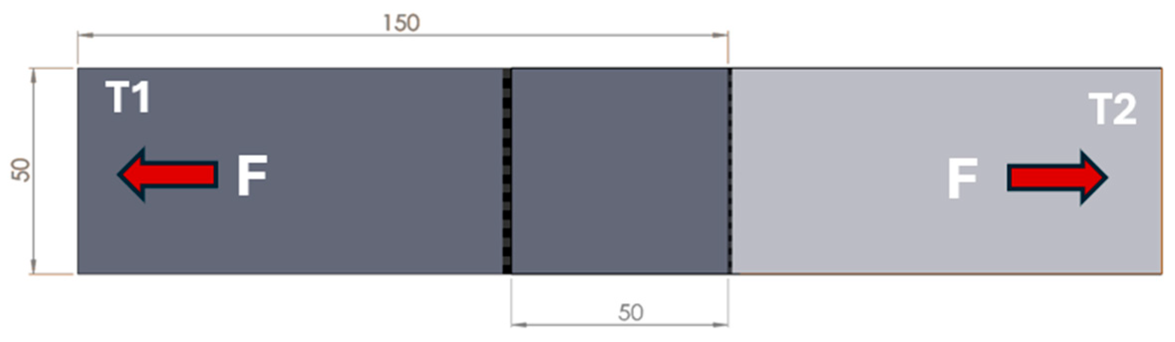
2. Materials and Methods
3. Results and Discussions
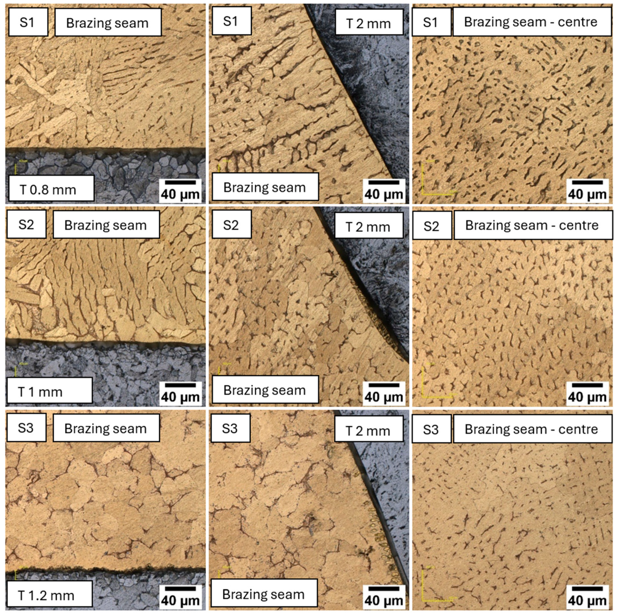
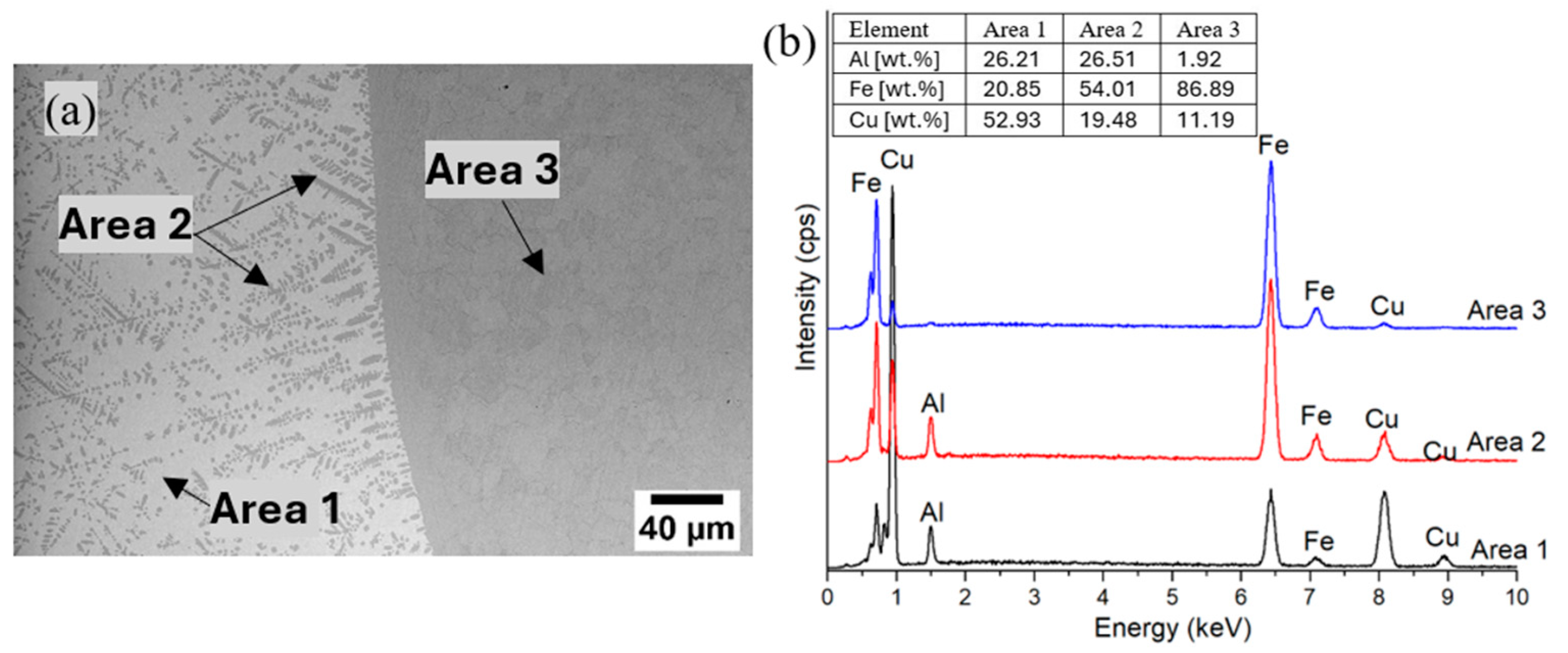
3.1. Macro- and Microstructural Observations
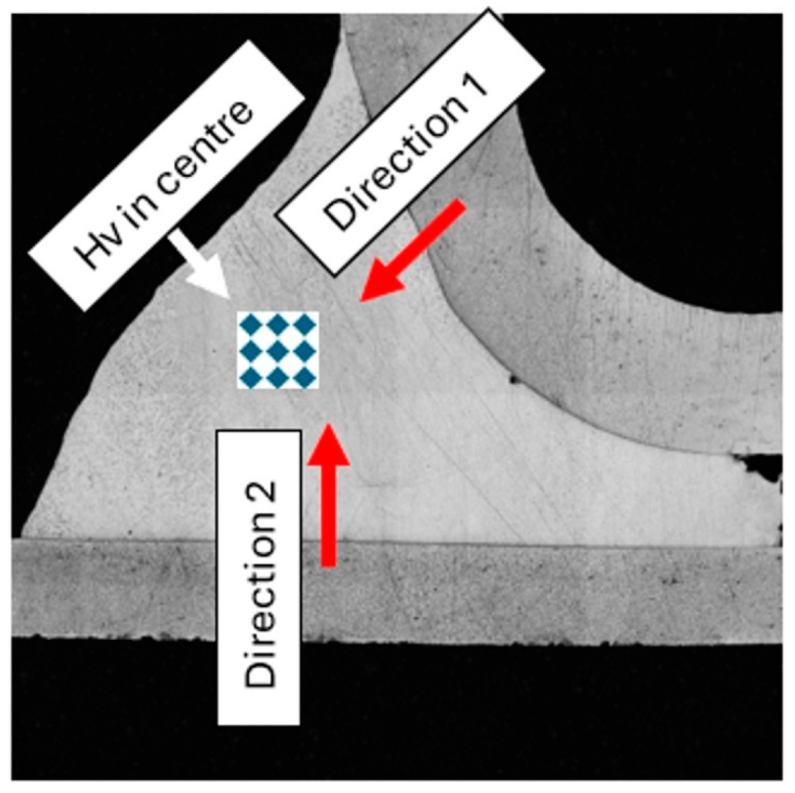
3.2. Mechanical Properties
4. Conclusions
- The specimens exhibited a heterogeneous microstructure, with variations in the shape and size of the grains due to differences in the cooling rate. Specimen 1 presented randomly oriented elongated grains, suggesting fast directional cooling; Specimen 2 had a coarser structure characterized by elongated grains; Specimen 3 has a heterogeneous granular microstructure consisting mainly of equiaxed grains, which is the result of a slower cooling process.
- The microstructure at the interface of the bead reveals a complex formation of α-dendrites surrounded by eutectic material, with intermetallics formed due to the dissolution of Fe from the base material into the bead alongside very fine spherical precipitates. The formation of intermetallics is more pronounced near the base material, likely due to the higher affinity of iron for aluminum compared to copper.
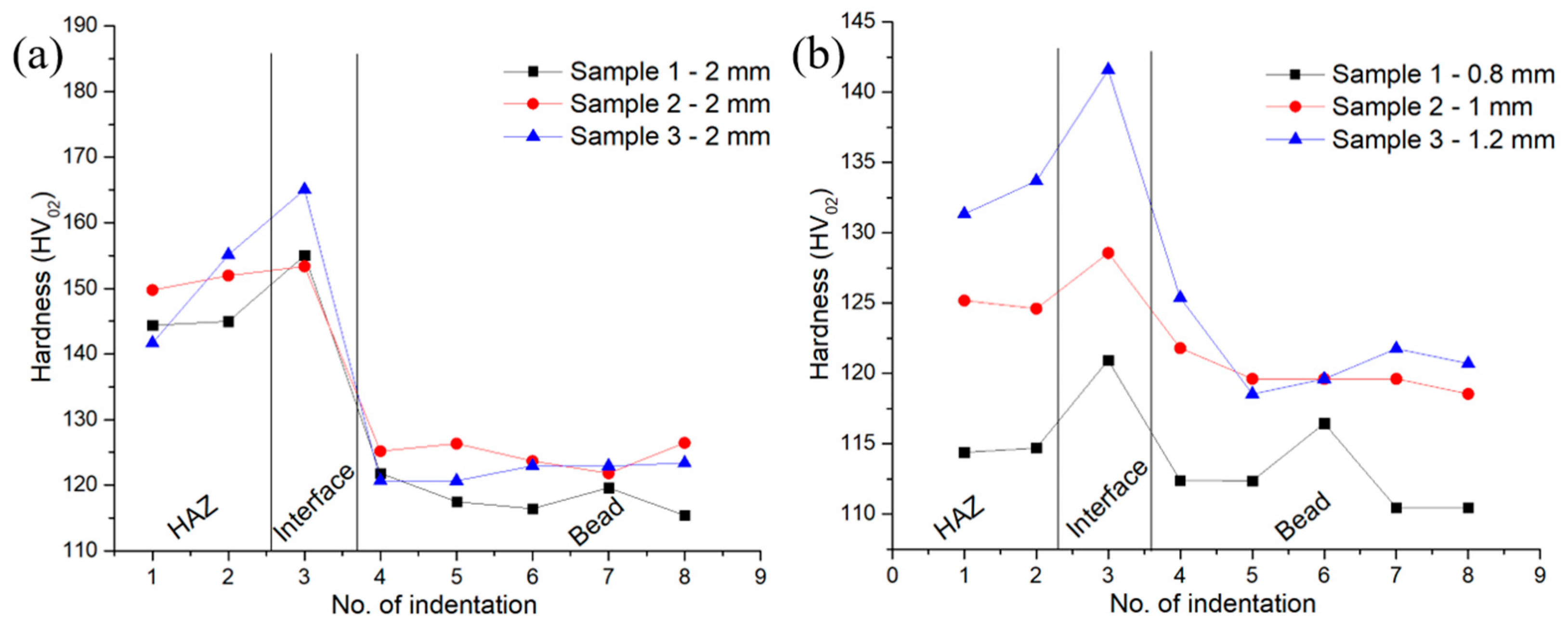
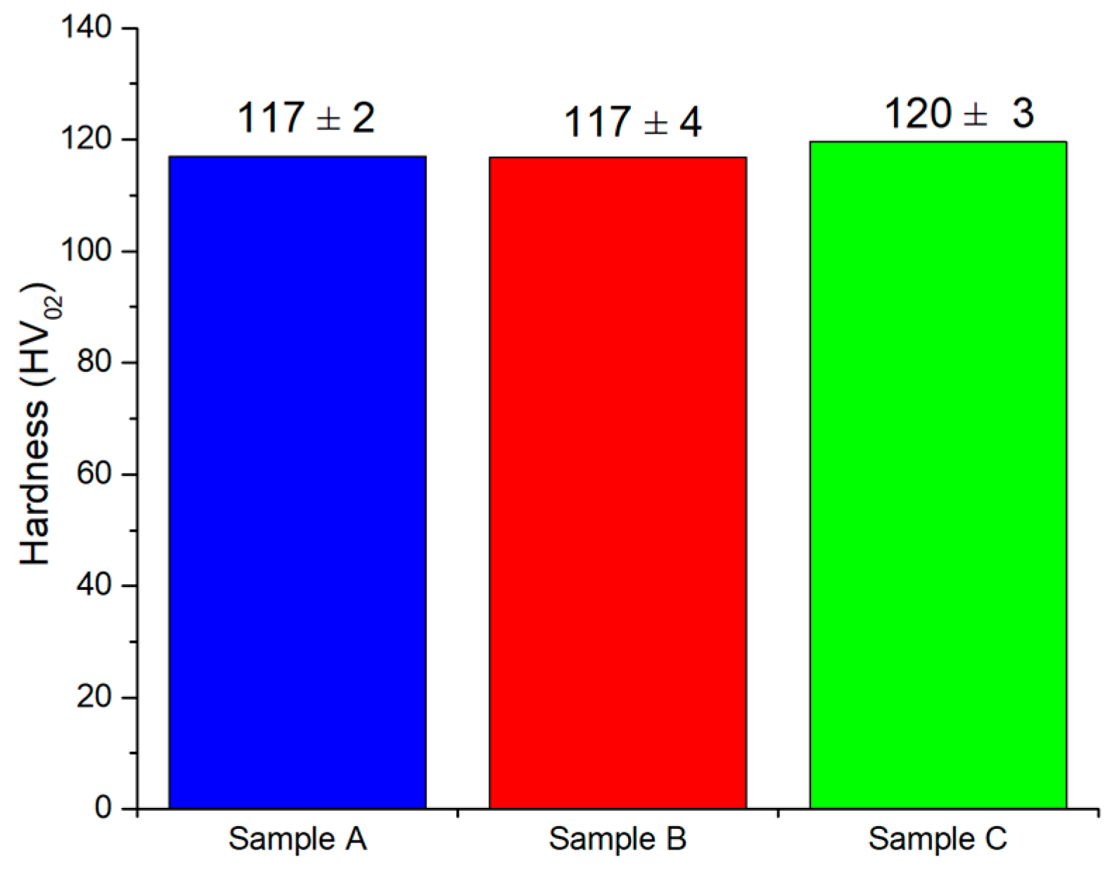
- In all samples, the interface shows the highest hardness values. The reason for this is that during brazing, an Fe–Al intermetallic layer with increased hardness is formed at the base material/bead interface. Besides, when the heat input is slightly increased, it can be seen that the hardness values in the areas close to the interface increase as well due to the formation of a higher volume of intermetallics. Since no intermetallic compounds are present at the center of the bead, there is no significant variation in hardness across this region.
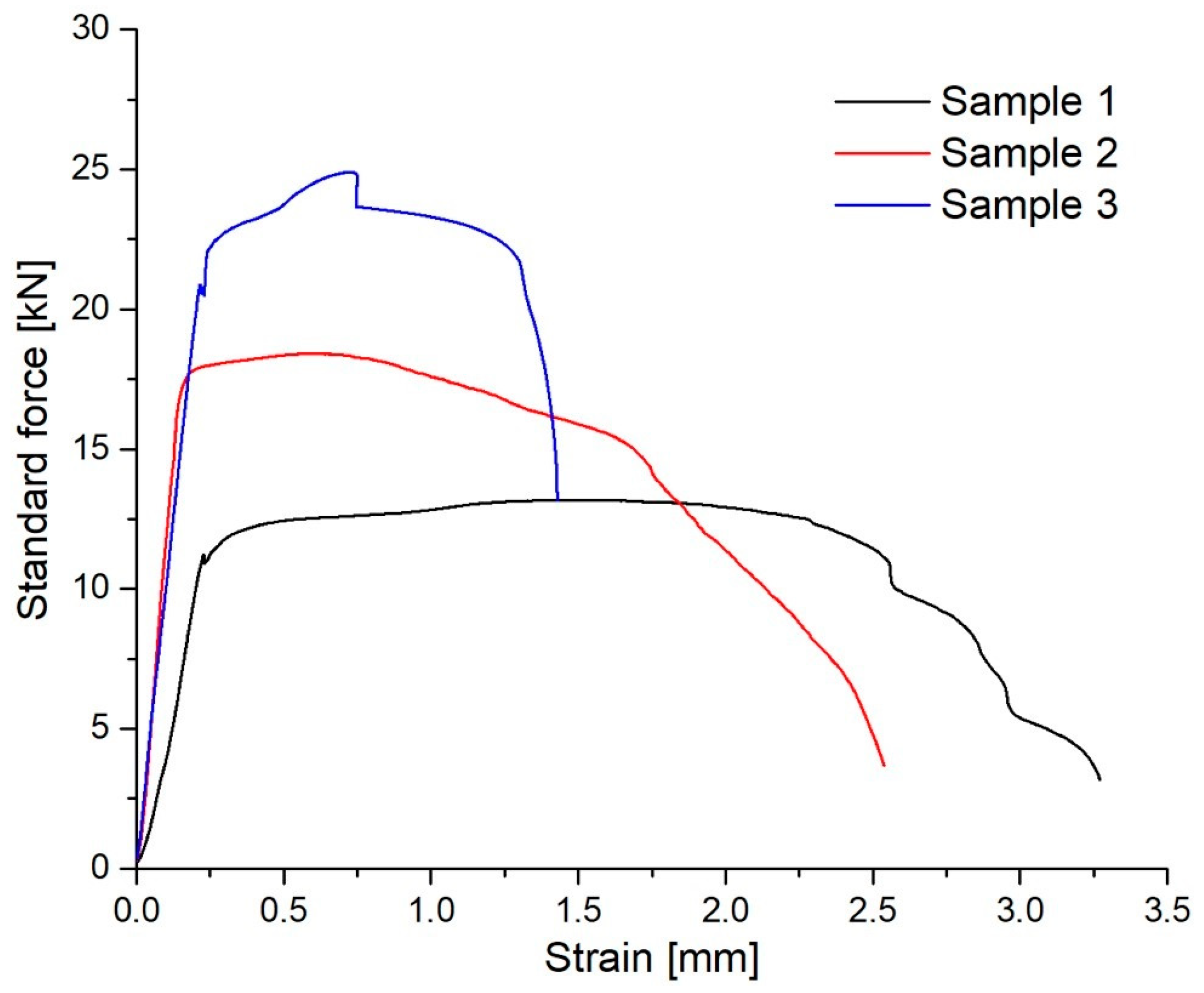
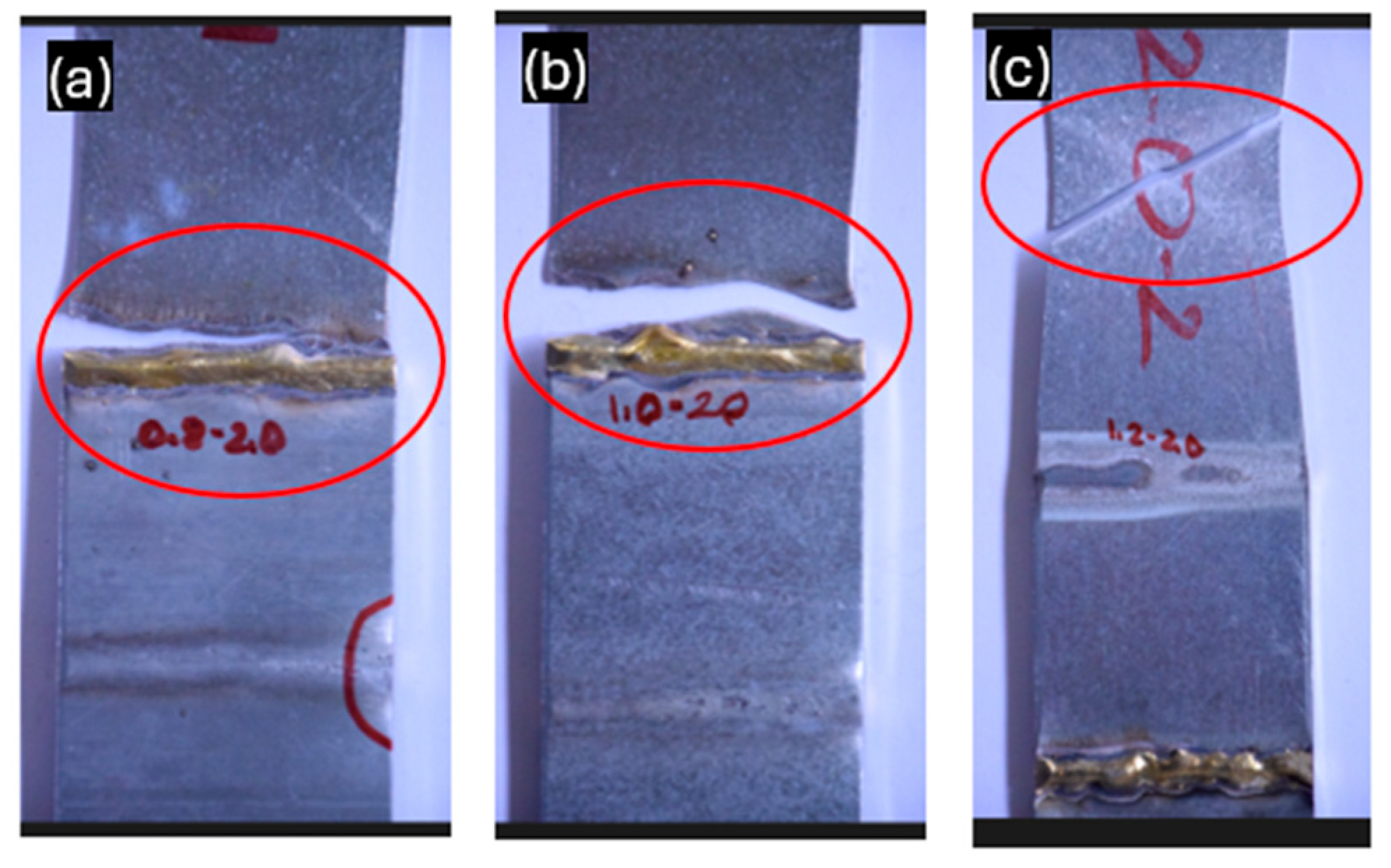
- An improved joint strength was obtained using a heat input of 121.4 J/mm and sheets of 1.2 and 2 mm thickness, which showed an increase in yield strength. In this case, a smooth ductile behavior was observed with failure of the base material at a distance of approximately 45 mm from the brazed joint, without fragile fracture in the HAZ.
Author Contributions
Funding
Data Availability Statement
Conflicts of Interest
References
- Ungureanu, V.; Both, I.; Burca, M.; Radu, B.; Neagu, C.; Dubina, D. Experimental and numerical investigations on built-up cold-formed steel beams using resistance spot welding. Thin-Walled Struct. 2021, 161, 107456. [Google Scholar] [CrossRef]
- Both, I.; Ungureanu, V.; Tunea, D.; Crisan, A.; Grosan, M. Experimental and Numerical Investigations on Cold-Formed Steel Beams Assembled by MIG Brazing. In Proceedings of the Eighth International Conference on Thin-Walled Structures—ICTWS, Lisbon, Portugal, 24–27 July 2018. [Google Scholar]
- Dubina, D.; Ungureanu, V.; Gîlia, L. Thin-Walled Structures Experimental investigations of cold-formed steel beams of corrugated web and built-up section for flanges. Thin-Walled Struct. 2015, 90, 159–170. [Google Scholar] [CrossRef]
- Tran, V.X.; Pan, J.; Pan, T. Fatigue behavior of spot friction welds in lap-shear and cross-tension specimens of dissimilar aluminum sheets. Int. Fatigue J. 2010, 32, 1022–1041. [Google Scholar] [CrossRef]
- Basak, S.; Pal, T.K.; Shome, M.; Maity, J. GMA brazing of galvannealed interstitial-free steel. Weld. J. 2013, 92, 29–35. [Google Scholar]
- Basak, S.; Das, H.; Pal, T.K.; Shome, M. Corrosion behaviour of MIG brazed and MIG welded joints of automotive DP600-GI steel sheet. J. Mater. Eng. Perform. 2016, 25, 5238–5251. [Google Scholar] [CrossRef]
- Singh, J.; Arora, K.S.; Shukla, D.K. Dissimilar MIG-CMT weld-brazing of aluminium to steel: A review. J. Alloys Compd. 2019, 783, 753–764. [Google Scholar] [CrossRef]
- Ye, Z.; Huang, J.; Gao, W.; Zhang, Y.; Cheng, Z.; Chen, S.; Yang, J. Microstructure and mechanical properties of 5052 aluminum alloy/mild steel butt joint achieved by MIG-TIG double-sided arc welding-brazing. Mater. Des. 2017, 123, 69–79. [Google Scholar] [CrossRef]
- Ghahfarokhi, S.S.; Kalashami, A.G.; Zhang, S.; Anousheh, A.S.; Midawi, A.R.H.; Yasnogorodski, V.; Zhou, Y.N.; Benoit, M.J. Investigation of the Critical Factors Influencing Mechanical Properties and Failure Behavior in Weld-Brazed ZnAlMg Coated Steel. Metall. Mater. Trans. A 2025, 56, 618–639. [Google Scholar] [CrossRef]
- Chovet, C.; Guiheux, S. Possibilities offered by MIG and TIG brazing of galvanized ultra high strength steels for automotive applications. Metall. Ital. 2006, 7-8, 47–54. [Google Scholar]
- Basak, S.; Pal, T.K.; Shome, M. High-cycle fatigue behavior of MIG brazed galvanized DP600 steel sheet joint-effect of process parameters. Int. J. Adv. Manuf. Technol. 2016, 82, 1197–1211. [Google Scholar] [CrossRef]
- Khan, M.S.; Cho, Y.; Zhang, S.; Goodwin, F.; Biro, E.; Zhou, Y.N. The Effect of Zinc Coating Type on the Morphology, Joint Geometry, and Mechanical Properties of Weld-Brazed Thin-Gauge Automotive Steel. Metall. Mater. Trans. A 2023, 54, 179–195. [Google Scholar] [CrossRef]
- Singh, J.; Shehryar, M.; Oliveira, J.P.; Singh, K. Brazing of high-strength steels: Recent developments and challenges. Manuf. J. Process. 2024, 115, 289–309. [Google Scholar] [CrossRef]
- Lee, K.B.; Oh, S.T. Development of durability enhancement technology for arc welding in advanced high strength steel (AHSS) chassis parts. J. Weld. Join. 2015, 33, 50–56. [Google Scholar]
- Singh, J.; Singh, K.; Kumar, D. High cycle fatigue performance of cold metal transfer (CMT) brazed C-Mn-440 steel joints. Int. J. Fatigue 2020, 137, 105663. [Google Scholar] [CrossRef]
- Sharma, A.; Lee, S.J.; Choi, D.Y.; Jung, J.P. Effect of brazing current and speed on the bead characteristics, microstructure, and mechanical properties of the arc brazed galvanized steel sheets. J. Mater. Process. Technol. 2017, 249, 212–220. [Google Scholar] [CrossRef]
- Yu, Z.S.; Li, R.F.; Qi, K. Growth behavior of interfacial compounds in galvanized steel joints with CuSi3 filler under arc brazing. Trans. Nonferrous Met. Soc. China 2006, 16, 1391–1396. [Google Scholar] [CrossRef]
- Reisgen, U.; Angerhausen, M.; Pipinikas, A.; Twiehaus, T.; Wesling, V.; Barthelmie, J. The effect of arc brazing process parameters on the microstructure and mechanical properties of high-strength steel HCT780XD using the copper-based filler metal CuAl8. J. Mater. Process. Technol. 2017, 249, 549–558. [Google Scholar] [CrossRef]
- Dharmendra, C.; Shakerin, S.; Ram, G.J.; Mohammadi, M. Wire-arc additive manufacturing of nickel aluminum bronze/stainless steel hybrid parts–Interfacial characterization, prospects, and problems. Materialia 2020, 13, 100834. [Google Scholar] [CrossRef]
- Singh, J.; Arora, K.S.; Shajan, N.; Shome, M.; Shukla, D.K. Influence of filler wire composition and heat input on microstructure and strength of CMT brazed DP steel joints. Mater. Res. Express 2019, 6, 116551. [Google Scholar] [CrossRef]
- Hulka, I.; Radu, B.; Ungureanu, V.; Sîrbu, N.A. Microstructural Investigation and Mechanical Properties of Resistance Spot Welding Joints of Mild Steel Sheets. Key Eng. Mater. 2024, 989, 57–63. [Google Scholar] [CrossRef]
- Duarte, V.R.; Rodrigues, T.A.; Schell, N.; Miranda, R.M.; Oliveira, J.P.; Santos, T.G. In-situ hot forging directed energy deposition-arc of CuAl8 alloy. Addit. Manuf. 2022, 55, 102847. [Google Scholar] [CrossRef]
- Xu, Z.; Li, X.; Li, S.; Jiang, R.; Hua, P.; Liu, D. Wire arc additive manufacturing of CuAl8Ni2/42CrMo bimetallic deposition: Microstructure and properties. J. Mater. Sci. 2025, 60, 2623–2639. [Google Scholar] [CrossRef]


| T1 [mm] | T2 [mm] | I [A] | Ua [V] | Protecting Gas Argon 4.6 [L/min] | Torch Tilting [°] | |
|---|---|---|---|---|---|---|
| Specimen 1 | 0.8 | 2 | 120 | 14.3 | 14–16 | 15–20 |
| Specimen 2 | 1 | 2 | 130 | 14.7 | ||
| Specimen 3 | 1.2 | 2 | 140 | 15.3 |
Disclaimer/Publisher’s Note: The statements, opinions and data contained in all publications are solely those of the individual author(s) and contributor(s) and not of MDPI and/or the editor(s). MDPI and/or the editor(s) disclaim responsibility for any injury to people or property resulting from any ideas, methods, instructions or products referred to in the content. |
© 2025 by the authors. Licensee MDPI, Basel, Switzerland. This article is an open access article distributed under the terms and conditions of the Creative Commons Attribution (CC BY) license (https://creativecommons.org/licenses/by/4.0/).
Share and Cite
Hulka, I.; Ungureanu, V.; Saraolu, S.; Popescu, A.; Pascu, A. Influence of Sheet Thickness and Process Parameters on the Microstructure and Mechanical Properties of Brazed Welding Used for Cold-Formed Steel Beams. Crystals 2025, 15, 354. https://doi.org/10.3390/cryst15040354
Hulka I, Ungureanu V, Saraolu S, Popescu A, Pascu A. Influence of Sheet Thickness and Process Parameters on the Microstructure and Mechanical Properties of Brazed Welding Used for Cold-Formed Steel Beams. Crystals. 2025; 15(4):354. https://doi.org/10.3390/cryst15040354
Chicago/Turabian StyleHulka, Iosif, Viorel Ungureanu, Silviu Saraolu, Alin Popescu, and Alexandru Pascu. 2025. "Influence of Sheet Thickness and Process Parameters on the Microstructure and Mechanical Properties of Brazed Welding Used for Cold-Formed Steel Beams" Crystals 15, no. 4: 354. https://doi.org/10.3390/cryst15040354
APA StyleHulka, I., Ungureanu, V., Saraolu, S., Popescu, A., & Pascu, A. (2025). Influence of Sheet Thickness and Process Parameters on the Microstructure and Mechanical Properties of Brazed Welding Used for Cold-Formed Steel Beams. Crystals, 15(4), 354. https://doi.org/10.3390/cryst15040354