Abstract
The present work is a comparative analysis of the properties of welded joints obtained during welding with the developed welding electrodes containing additives of photocatalysts of nanostructured functional ceramics (PNFC) brand ZB-1 (IMAN-7) and the ESAB E6013 welding electrodes. This study investigates the weld morphology, microstructure, and mechanical properties of Shield metal arc welding (SMAW) welded joints. The results of the studies showed that the introduction of PNFC brand ZB-1 into the coating of welding electrodes up to 1% has a beneficial effect on the melting ability and stability of the welding arc, formation of the bead, microstructure of the weld bead, and mechanical properties of the welded joints. It was found that IMAN-7 electrodes, compared to the ESAB E6013 electrodes, have better performance in terms of arc penetration, bead metal structure, and relative elongation of welded joints. In addition, the high melting capacity of the IMAN-7 electrode allows for economic advantages, such as increased productivity and a two-fold reduction in electrode consumption.
1. Introduction
Many industries use welding fabrication to join materials in a solid-state manner or through melting, as in the case of fusion welding techniques [1]. This work focuses on Shielded Metal Arc Welding (SMAW). SMAW is a versatile joining process used for fabricating pressure vessels and boilers. It offers high-quality welds and is critical for manufacturing steel structures, particularly in the oil and gas sectors [2]. SMAW is a manual joining process characterized by its flexibility and transportability across various working conditions and environments [3]. However, the main drawback is the loss of the electrode material owing to weld spatter. This affects productivity due to weld cleanup, and restoration [4].
Many works have been dedicated to coating welding properties to enhance welding technology properties. Sumit et al. [5] investigate the effect of CaO-CaF2-SiO2 and CaO-SiO2-Al2O3 compounds contained in flux electrodes on electrode weight loss. Vijaya et al. [6] focus on the influence of CaF2-SiO2-CaO-22.5%TiO2 SMAW electrode coating on microstructure welds and high-temperature wettability. Aditya et al. [7] discussed the design and thermal property characterization of SMAW electrode coating fluxes, highlighting the effects of various constituents like CaF2, CaO, and SiO2, on weight loss, thermal diffusivity, and overall flux stability during welding processes. Other studies have focused on the effects of coating flux composition on weld morphology and mechanical properties. Adel et al. [8] studied the influence of chrome-based coatings and the electrical current used on the mechanical properties of low-carbon steels. Musa et al. [9] investigated the effects of four welding electrodes(E6013, E6014, E308L-16, and AG4700) on mild steel SMAW weldments tensile strength, hardness, impact energy, and microstructure. The results show that the welds made with mild steel electrodes (E6013 and E6014) exhibited higher tensile strengths in both heat-treated and untreated conditions. Kolhe et al. [10] investigated the influence of SMAW welding parameters on the mechanical properties of S355JR mild steel using an E6013 electrode. The tensile strength and hardness of the weld zone reached 494.47 MPa and 269.77 Hv, respectively.
Owing to their diversity and characteristics, nanomaterials have been widely applied in various industries, including power plants, construction, agriculture, healthcare, manufacturing, defense, electronics, energy, information technology, transportation, and biotechnology. In recent years, the use of nanomaterials has experienced a significant increase. Additionally, nanomaterials can be tailored to meet specific requirements in terms of size, shape, and properties [11].
In SMAW, the nanopowder is introduced into the electrode coating or by surfacing the electrode on the electrode coating. In the case of shielding gas welding with consumable electrodes using a solid wire, a nanopowder is coated on the surface wire or the nanopowder is introduced in the shield gas. The filler wire contains the nanopowder in the Tungsten inert gas welding (TIG) technique. In the Submerged arc welding method, the powder is incorporated in the flux or deposited onto the edges of the part to be joined [12,13,14]. Liquid glass is an effective binder because it ensures a uniform distribution of nanopowder in the volume [15]. Liquid glass facilitates the uniform dispersion of nano-powders, such as Al2O3, during the welding process, which is essential for consistent weld quality[dd]. The glass effectively wets metal surfaces, promoting the rearrangement of metal particles and reducing the porosity in the weld [16].
Rahul et al. [17] developed using nano-arc stabilizer coating and nano-particle substitution, reducing fume production by 82% and Cr(VI) concentration by 68% in fumes, and 36% and 52% in inhalable and respirable fumes, respectively. The use of nano-powders would significantly enhance existing technological processes and create new production methods. Nanopowders have a high specific surface area, which makes it possible to provide high reactivity with a low content [18].
RCrO3 ceramic materials, where R is a rare earth oxide such as yttrium oxide, are highly beneficial for applications where electrical conductivity is important, such as in electrodes. However, these materials have some limitations. They are not very stable chemically at high temperatures above 1600 °C. They can also be damaged by thermal cycling at temperatures above 1500 °C and cannot withstand rapid heating. These issues render them less suitable for applications in which stability is crucial. Consequently, there is a demand for more durable ceramic materials made from rare-earth oxides that can be utilized in applications where electricity is required and in environments with high temperatures [19].
Photocatalyst additives are a new research field for improving the welding and technological properties of welding electrodes. Therefore, the main characteristics, such as the metal melting coefficient, electrode fused quantity coefficient, surfacing coefficient, and loss coefficient, indicate that the losses are due to spattering and oxidation [20]. Rajeswari et al. introduced nano TiO2 as a photocatalyst additive in SMAW electrodes, significantly reducing the fume formation rate by up to 21% and hexavalent chromium concentration by up to 42%, thereby enhancing the mass transfer efficiency during welding [21].
Infrared radiation synthesis enables the required amount of material to be obtained. In this regard, studies were conducted in [22] to study the effect of infrared radiation synthesized in the furnace of the NFC photocatalyst “ZB-1”.
This catalyst was added in small quantities (from 0 to 8%) to the popular brand of MR-3 welding electrode to evaluate its welding and technological characteristics. Thus, the work [20] presents the results of studies on the effect of ZB-1 photocatalyst additives on the welding and technological properties of MR-3 welding electrodes. The authors developed a welding electrode containing additives of photocatalysts of nanostructured functional ceramics (PNFC) branded ZB-1 (IMAN-7) [20]. According to the results of this work, the optimal amount of photocatalyst that effectively affects the welding and technological properties of the MR-3 welding electrode is the addition of ZB-1 up to 1%. This work aims to continue the study of the effect of the ZB-1 PNFC additive up to 1% in the coating of the MR-3 welding electrode on the quality and properties of welded joints on carbon steel AISI 1017. In particular, we will focus on studying the effect of these additives on the formation, microstructure, and mechanical properties of welded joints obtained when welding with electrodes with small amounts of ZB-1 PNFC added to the coatings. In addition, to assess the quality and properties of carbon steel beads and their compliance with international standards, we conducted a comparative analysis of new welding electrodes with ESAB E6013 welding electrodes, which are widely used in the world market.
2. Materials and Methods
2.1. Materials and Welding Procedure
The first part of this study provides detailed information on the composition of the ZB-1 photocatalyst, the MR-3 welding electrode, and the technologies used for their manufacture [20].
A preproduction pilot lot of IMAN-7 welding electrodes was carried out at a plant to produce welding electrodes from a flux developed and manufactured by the authors of this work.
The chemical composition of low carbon AISI 1017 steel plates, electrodes E-6013, Iman-7 welding rods, and ZB-1 additives are listed in Table 1, Table 2, Table 3 and Table 4, respectively.

Table 1.
Chemical composition of low AISI 1017 steel (weight %).
Table 2.
Chemical composition of the ESAB E6013 welding rod (AWS: SFA 5.1 E6013).
Table 3.
Chemical composition of the IMAN-7 welding rod.
Table 4.
Chemical composition of the additives ZB-1.
The welding electrodes were obtained by applying a coating to the surface of the Sv-08A wire (see Table 3), with a diameter (d) of 2.8 mm, obtained by mixing the flux with potassium liquid glass, with a density of 1.4 g/cm3 in an amount of 25% of the flux weight. The potassium liquid glass is a binder that ensures the uniform distribution of the nanopowder in the volume.
The flux consisted of a mixture of 99% of the coating powders of the MR-3 electrode and 1 wt.% of the ZB-1 photocatalyst additive. After the welding electrodes were manufactured, they were dried in a drying cabinet at a temperature of 80 °C for 40 min and calcined at 180 °C for 40 min. The total thickness (D) of the IMAN-7 welding electrode was 4.4 mm, while the coating thickness (D/d) was 1.57 (corresponding to a thick coating of 1.45 < D/d ≤ 1.80). ESAB E6013 electrodes with 2.6 mm diameter are used in this study for comparison with the new IMAN-7 electrodes. The ESAB E6013 electrodes are coated with rutile type and comply with the AWS: SFA 5.1 E6013 standard used for sheet metal, general fabrication, and structural welding work. These electrodes are well-known and widely distributed in the world market [23].
The SMAW method is used to join the plates in the butt design. The experiments consist of welding a 20 cm line of low carbon steel AISI 1017 1.8 mm thick. The E-6013 and IMAN-7 electrodes with 2.6 mm diameter and 2.8 mm, respectively, were used as filler materials. Before welding, the plates were cleaned using acetone. During SMAW welding, only the current is adjusted, and the welding current is set to 40 A. Arc voltage is derived from the arc length, which the welder must maintain.
2.2. Morphology Investigation
Figure 1 depicts the different specimens cut from the welded plates. The bead morphologies of both SMAW beads, performed by ESAB E6013 and IMAN-7, were analyzed. The samples were polished up to 1200 grit fineness, followed by cloth polishing. The AISI 1017 bead zone was etched using a Nital solution (95 cc ethylene + 5 cc HNO3).
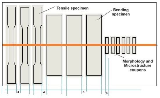
Figure 1.
Test specimen for the tensile test (units in mm).
2.3. Microstructure Investigation
The microstructural evolution of the fusion zone was investigated using a JEOL JSM-7600F scanning electron microscope (SEM) (JEOL, Tokyo, Japan). The samples are cut, and embedded in a resin. The mounted samples were then ground and polished. Abrasive particles are used in successively finer steps to remove material from the surface, followed by cloth polishing to a 0.05 µm alumina surface finish. Then, samples were etched using a Nital solution. Samples with 32 mm diameter are used for SEM investigation. SEM parameters included magnification (M = x 500), accelerating voltage (15 kv), and working distance (WD = 8 mm).
2.4. Hardness Test
Vickers hardness tests were performed by a digital hardness tester model HVS-50 (SCTMC, Shanghai, China) with a standard load of 10 Kgf and a dwell time of 10 s. The test was conducted according to the ASTM E-384-99. Figure 2 displays the hardness line(horizontally and vertically) and track indentation. The measurements were performed on each sample using E6013 and IMAN-7 electrodes. The hardness line measurements are far from the top surface by 0.75 mm.
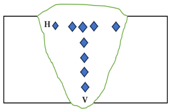
Figure 2.
Vickers hardness test specimen according to the ASTM E-384-99.
2.5. Tensile Test
The tensile tests were carried out at room temperature (24 °C). They were performed with a computer-controlled electro-hydraulic servo universal testing machine model WAW-300E (Jinan testing equipment IE, Jinan, China). The crosshead speed was 0.5 mm/min, the loading rate was 0.5 kN/s, and the strain rate was 1.6 × 10⁻⁴ s−1. The specimens were cut according to ASTM E8M-04, as shown in Figure 3. The tensile tests were carried out on 3 samples of each type of electrode.
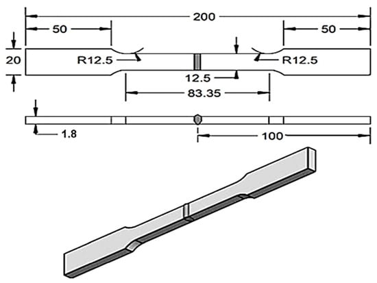
Figure 3.
Tensile test specimen according to ASTM E8M-04 (units are in mm).
2.6. Bending Test
Transverse bend test specimens were prepared according to ASTM E190-14, as displayed in Figure 4. The bending test was conducted according to the standard using guided-bend specimens in a test jig. A face bending test was carried out. A load was applied to the root side so that the weld face would be in tension. The specimens were bent into a U-shape using a universal tensile machine. The test evaluates the material’s ductility by checking for cracks or other surface defects after bending.
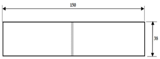
Figure 4.
Transverse bend specimen according to ASTM E190-14 (dimensions are in mm).
3. Results and Discussions
3.1. Line Weld and Weld Bead Aspect
When welding 1.8 mm thick low carbon steel AISI 1017 using a butt joint design and a current intensity of 40 A, the welding technological properties of the ESAB E6013 and IMAN-7 welding electrodes can be summarized as follows:
- -
- the arc is easily excited and stably maintained;
- -
- the coating melts evenly and without excessive spattering;
- -
- the slag formed during welding ensures the correct formation of bead seam;
- -
- during the external inspection, no defects (cracks, pores) were found in the beaded metal, either when welding with an E6013 electrode or an IMAN-7 electrode.
Figure 5 and Figure 6 show photographs of the welded joints captured from the welding side (Figure 5a and Figure 6a) and back side (Figure 5b and Figure 6b) during welding with the investigated electrodes E6013 and IMAN-7. On the back side of the welded plates, the bead formed using the IMAN-7 electrode demonstrated a smooth surface and full penetration through the entire thickness of the metal (Figure 6b). In contrast, the beads on the plates welded with the E6013 electrode did not exhibit complete penetration (Figure 5b).
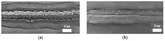
Figure 5.
Views of welded joints performed with the ESAB E6013 electrode from the front side (a) and backside (b).
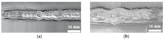
Figure 6.
Views of welded joints performed with the IMAN-7 electrode from the front side (a) and the backside (b).
The greater penetration capacity of the IMAN-7 welding electrode compared with that of the ESAB E6013 electrode is evident in the cross-sectional images of the seams presented in Figure 7. Compared to the E6013 welding electrodes, when welding with the IMAN-7 welding electrodes, the depth of weld metal penetration increases by 40%.
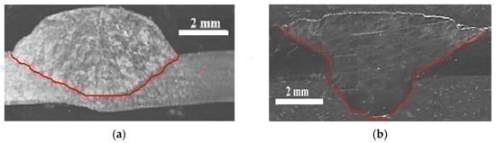
Figure 7.
Macrographs of beads performed with E 6013 electrode (a) and IMAN-7 electrode (b).
Welding beads made using the IMAN-7 welding electrode achieved complete penetration in a single pass (see Figure 7b), unlike those made using the E6013 electrode, which exhibited incomplete penetration (see Figure 7a). Therefore, to ensure complete penetration in the E6013 beads, a backside bead was added (see Figure 8). Then, comparative tests were conducted on the mechanical properties of the welded joints.
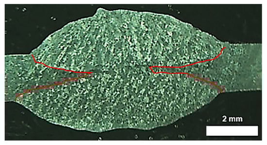
Figure 8.
Cross-section of a bead made with electrode E 6013 welded from both sides.
The increased rate of melting in the IMAN-7 electrode is likely caused by the addition of a small amount of PNFC ZB-1 additive to its coating. This effect can be explained by the quantum tunneling effect (ITE), a phenomenon in which particles or waves overcome a potential barrier due to the accumulation of a significant energy pulse [22].
The ITE provides a very narrow energy range associated with the pulse rise time of the energy pulse. By finely tuning the pulse rise time to match the energy requirements of the target process, the ITE operates with high selectivity, directing all pulse energy into the desired narrow range. This allows for maximizing the efficiency of the welding arc penetration by optimally matching the pulse characteristics and required energy [22].
A high-quality weld joint can be obtained by welding with the E6013 electrode using two-sided welding, while with the IMAN-7 electrode, one-sided welding is sufficient at the same welding speed, welding current, and voltage. Hence, welding with ESAB 6013 results in an electrode consumption that is approximately twice as high as that when using the IMAN-7 electrode. The savings in electrode consumption will be approximately 50%. Similarly, the power consumption will be approximately twice as much with two-sided welding. The savings in electricity will also be approximately 50%. The savings in electricity and electrode consumption will be approximately 50%. This is an approximate value, since in practice, there may be small deviations due to various factors, such as welding quality and energy losses in the welding circuit.
3.2. Microstructure Assessment
The SEM images (Figure 9a,b) were obtained at the center of the weld bead. Figure 9a,b show ferrite-pearlite microstructure. The ferrite in the image is light in color, and the perlite is dark in color. Figure 9b shows that the weld performed with IMAN-7 electrode exhibits finer ferrite-pearlite structure of the bead metal and a uniform distribution of pearlite throughout the bead volume.
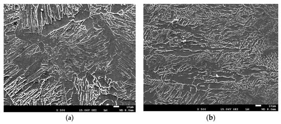
Figure 9.
Bead zone SEM images of specimens welded using the ESAB E6013 electrode (a) and IMAN-7 electrode (b) (500×).
3.3. Hardness Test
Vickers hardness measurements of the bead metal, conducted horizontally and vertically along the beads, revealed higher hardness values for the bead metal produced using the IMAN-7 electrodes (Table 5 and Table 6). For a welding bead made with an E6013 electrode, the horizontal hardness was measured along two lines (Figure 10) along the horizontal lines of the bead from the front side and the backside. Furthermore, the hardness values of the bead metal created with both electrodes were higher than those of the welded AISI 1017 steel (Table 7).
Table 5.
Horizontal Hardness measurement: 10 kgF.
Table 6.
Vertical Hardness measurement: 10 kgF.
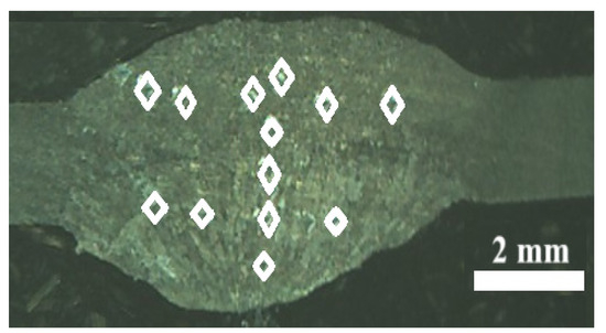
Figure 10.
Indentation locations during the Vickers hardness test on a bead performed with electrode E 6013.
Table 7.
Hardness measurement: 10 kgF.
The obtained results showed that the hardness of the top and back side beads made with E6013 electrodes had different values. This can be explained by the fact that the top bead is subjected to heat when making the bottom bead, and the top bead metal is annealed, which helps reduce its hardness. It is known [24] that when welding double-sided two-pass welded joints, the test section includes the metal at the intersection of the internal and external beads, this is due to the presence of local embrittlement zones formed in the metal of the internal bead due to its heating when making the external bead.
Following the Interstate standard GOST 23118-99 [25], which regulates the requirements for welds of metal structures, the joint metal hardness index should not exceed 350 HV for structures of group 1 (high-quality level) and not more than 400 HV for structures of other groups. The results of the measurements of the hardness of the HV welds (see Table 4 and Table 5), made with electrodes E6013 and IMAN-7, show their compliance with the requirements of this standard.
3.4. Tensile Test
Figure 11 and Figure 12 show images of the specimens after the tensile testing of the AISI 1017 welded steel beads made using the E6013 and IMAN-7 electrodes. The tensile test results indicate that all welded specimens fractured in the base metal, regardless of the welding electrode used.
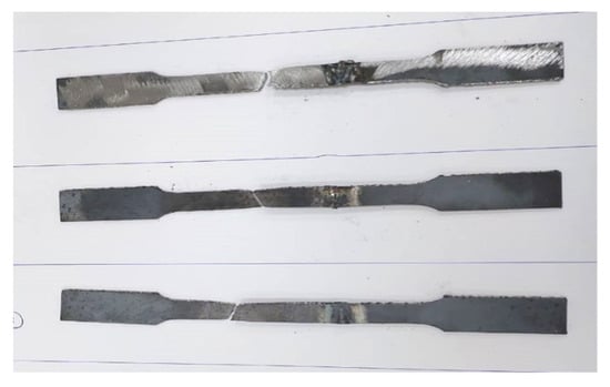
Figure 11.
Tensile specimen for beads performed with an E 6013 electrode after breaking.
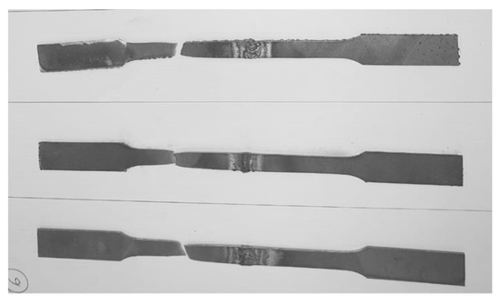
Figure 12.
Tensile specimen for beads performed with an IMAN-7 electrode after breaking.
Table 8 presents the yield strength (YTS) results, according to which the yield strengths of the welded joints made with both studied electrodes, in their indicators, are not lower than 0.9 of the yield strength of the welded base metal. These results indicate the high load-bearing capacity of welded joints, avoiding residual deformation. These yield strength indicators show that the AISI 1017 SMAW welded joints fabricated using the E6013 and IMAN-7 electrodes can withstand the load safely.
Table 8.
Yield strength test for beads performed with E6013 and IMAN-7 electrodes and base metal 1017 steel.
Tensile strength tests showed that welded joints obtained by welding with the E6013 electrode had a tensile strength slightly lower than that of joints made with the IMAN-7 electrode (Table 9). However, given that the breaking zone of the welded samples made with both electrodes occurred in the base metal zones, it can be stated that these welded joints are equal in strength to the base metal. The ultimate tensile strength (UTS) obtained in the present work (388.7–389 MPa) is in good agreement with the results obtained by Zoalfakar et al. [26] in their study on the optimization of SMAW parameters to enhance the mechanical properties of carbon steel (ST 37/2, and ST44/2) joints. The value of UTS obtained was 380 MPa. Table 9 lists the maximum, minimum, average, and standard deviation of the UTS. The standard deviation is less than 10 MPa which is an indicator of the reliability of the experiments and samples that were prepared.
Table 9.
Tensile strength tests for beads performed with E6013 and IMAN-7 electrodes and base metal 1017 steel.
Furthermore, the relative elongation of the IMAN-7 beads is slightly higher than that of the E6013 beads but lower than that of the base metal (Table 10).
Table 10.
Elongation at Break (in 88 mm) δ [%].
3.5. Bending Test
Additionally, bending tests were conducted on the welded joints, and the results indicate high bending angle values for both electrode types (Figure 13 and Table 11). The specimens were bent at an angle of 180° without cracking, indicating their ductility. These results show good results for the welds obtained using both tested electrodes. The standard deviation represents a measure of the amount of variation or dispersion of a set of values. For strength measurements, the standard deviation is less than 8 MPa.
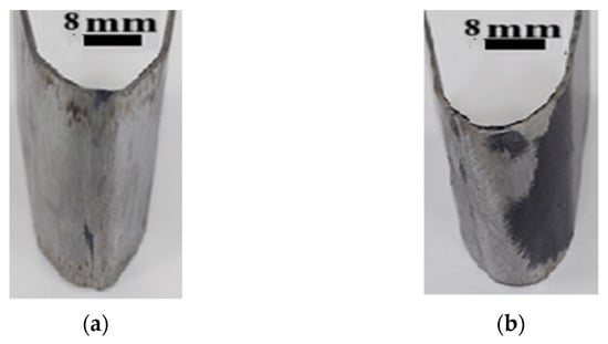
Figure 13.
Welded samples of the bending test performed with the ESAB E6013 electrode (a) and IMAN-7 electrode (b).
Table 11.
Bending test face test (load vs. extension).
The improved mechanical properties of the welded joints obtained using the IMAN-7 electrodes compared with those using the E6013 electrodes can likely be attributed to the finer ferrite-pearlite structure of the bead metal and the uniform distribution of pearlite throughout the bead volume.
4. Conclusions
The present work aims to compare the new PNFC grade ZB-1 (IMAN-7) welding electrode with the ESAB E6013 welding electrode. The investigations included the morphology, microstructure, and mechanical properties of the welds. The electrodes were tested on AISI 1017 sheet metal with 1.8 mm thickness. The main findings are summarized as follows:
- Under the same welding conditions, the weld bead carried out with the developed IMAN-7 electrodes had a fully penetrated depth weld. However, the joint performed with E6013 electrodes allowed for partial depth penetration. Moreover, the depth penetration of the bead welded with IMAN-7 is higher than that of E6013 by 40%.
- Using new electrodes allows for a reduction in the electricity cost, working time, and electrode consumption by approximately 50%.
- The weld Vickers hardness readings of welds made with the E6013 and IMAN-7 electrodes exhibit values up to 190 Hv and 160 Hv, respectively. Both welds show good agreement with the requirements of the Interstate standard GOST 23118-99 and relate to high-quality structures.
- The yield strength (YTS) values of the welded joints made by both electrodes under study are at least 0.9 of the yield strength of the metal being welded and indicate a high bearing capacity of the welded joints, which does not lead to permanent deformation and can safely withstand the load.
- The tensile strengths (UTS) of the welded joints obtained by welding with the E6013 and IMAN-7 electrodes are 388.7 MPa and 389 MPa, respectively, and are slightly lower than that of the base metal (397 MPa). This is also evidenced by the fact that the destruction of the welded samples occurred on the base metal.
- The weld joint performed with the IMAN-7 electrode has an elongation of 13.4 mm, which is slightly higher than that of the joint performed with the E6013 electrode (12.6 mm) and both still lower than that of the base metal specimen (16.2 mm). The plastic properties of the welded joints show good results for welds obtained using both tested electrodes.
- The study revealed that the microstructure of the bead metal produced using the IMAN-7 electrodes exhibited a finer grain size ferrite-pearlite structure and a uniform distribution of pearlite compared to the microstructure of the beads produced using the E6013 electrodes.
- Further research is needed to investigate the long-term performance and application of IMAN-7 electrodes in different welding environments.
Author Contributions
Conceptualization, S.R.M., R.R.K. and K.T.; methodology, S.R.M., R.R.K. and K.T.; software, R.R.K., S.R.M. and K.T.; validation, S.R.M. and K.T.; formal analysis, S.R.M. and K.T.; investigation, S.R.M., K.T. and J.P.; resources, K.T. and J.P.; data curation, S.R.M.; writing—original draft preparation, S.R.M. and K.T.; writing—review and editing, S.R.M., R.R.K. and K.T.; visualization, S.R.M. and K.T.; supervision, S.R.M. and K.T. All authors have read and agreed to the published version of the manuscript.
Funding
This research received no external funding.
Data Availability Statement
The data used to support the findings of this study are included in this article.
Conflicts of Interest
The authors declare no conflicts of interest.
References
- Carles, Y.A.N.; Aditya, M.B.; Fitradi, G.A.P.P.; Mardit, N.N.; Ryan, P.S. Analysis of Electric Current on Aluminum Plate Welding Using SMAW (Manual Metal Arc) Method. Int. Conf. Artif. Intell. Navig. Eng. Aviat. Technol. (ICANEAT) 2024, 1, 144–146. [Google Scholar] [CrossRef]
- Mohsin, I.; Qazi, R.A. Application of Taguchi Method for Optimization of Tensile Strength of Shielded Metal Arc Welding (SMAW) Process for Steel SA 516 Grade 70. Int. J. Progress. Sci. Technol. (IJPSAT) 2019, 17, 97–103. [Google Scholar] [CrossRef]
- Rubén, L.L.; Sergio, R.G.; Celia, S.F.; Marina, C.B. Shielded Metal Arc Welding (SMAW): Determining the Thermal Fields With FEM and RSM. In Proceedings of the 9th International Conference on Smart and Sustainable Technologies (SpliTech), Bol and Split, Croatia, 25–28 June 2024; pp. 1–6. [Google Scholar] [CrossRef]
- Asati, B.; Vidyarthy, R.S. A Method for Evaluation of Welding Performance of SMAW Electrodes. In Advances in Industrial Machines and Mechanisms; Lecture Notes in Mechanical Engineering; Springer: Singapore, 2021; pp. 597–608. [Google Scholar] [CrossRef]
- Sumit, M.; Chhibber, R. Design and Development of Shielded Metal Arc Welding (SMAW) Electrode Coatings Using a CaO-CaF2-SiO2 and CaO-SiO2-Al2O3 Flux System. JOM 2019, 71, 2435–2444. [Google Scholar] [CrossRef]
- Vijay, K.; Rahul, C.; Sumit, M. Investigations on wetting and structural behavior using CaF2-SiO2-CaO-22.5%TiO2 SMAW electrode coating for AUSC applications. Proc. Inst. Mech. Eng. Part L J. Mater. Des. Appl. 2023, 237, 1861–1873. [Google Scholar] [CrossRef]
- Aditya, K.; Chhibber, R. Thermal property characterization and modeling of SMAW electrode coating flux using ANN and regression analysis. Proc. Inst. Mech. Eng. Part B J. Eng. Manuf. 2024, 0(0). [Google Scholar] [CrossRef]
- Netto, A.E.; Turazi, A. Estudo dos efeitos da aplicação de revestimentos duros em aço baixo carbono através do processo de soldagem SMAW. Tecnol. Metal. Mater. Mineração 2022, 19, e2397. [Google Scholar] [CrossRef]
- Musa, A.A.; Abdullahi, I.; Sani, A.D.; Jimoh, A.I. Effect of welding electrodes and post-weld heat treatment on some mechanical properties and microstructural transformations of mild steel weldment using SMAW process. Niger. J. Eng. 2023, 30, 30–35. [Google Scholar] [CrossRef]
- Kolhe, K.P.; Teshome, F.; Mulu, A. Effects of Shielded Metal Arc Welding Process Parameters on Mechanical Properties of S355JR Mild Steel. In Advances of Science and Technology. ICAST 2019. Lecture Notes of the Institute for Computer Sciences, Social Informatics and Telecommunications Engineering, Bahir Dar, Ethiopia, 2–4 August 2019; Springer: Cham, Switzerland, 2019; Volume 308, pp. 525–536. [Google Scholar] [CrossRef]
- Camargo, P.H.C.; Satyanarayana, K.G.; Wypych, F. Nanocomposites: Synthesis, Structure, Properties and New Application Opportunities. Mater. Res. 2009, 12, 1–39. [Google Scholar] [CrossRef]
- Kuznetsov, M.A.; Zernin, E.A. The Current State of Application of Ultra- and Nanostructured Powders in Technologies in Welding Technologies (Review). Mater. Sci. Forum 2018, 927, 20–28. [Google Scholar] [CrossRef]
- Sapozhkov, S.B.; Zernin, E.A.; Petrova, E.D.; Petrov, R.V.; Zakharov, M.A. The use of nano- and ultrafine materials for controlling the structure and properties of metals in connecting technologies: World practice (review). Vestn. Novgorod. Gos. Univ. 2023, 5, 833–846. [Google Scholar] [CrossRef]
- Zernin, E.A.; Петрoва, Е.В.; Scherbakov, A.; Pozdeeva, E.O.; Blohin, A. Application of Tungsten Nanopowder in Manual Metal Arc, Metal Inert Gas, and Flux-Cored Arc Welding Surfacing. Superalloys 2024, 14, 1376. [Google Scholar] [CrossRef]
- Kuznetsov, E.A.; Zernin, V.I.; Danilov, D.S. Application of Nanostructured Powders to Control Characteristics of Electrode Metal Transfer and the Process of Weld Structurization. Appl. Mech. Mater. 2013, 379, 199–203. [Google Scholar] [CrossRef]
- Tanaka, H.; Matsubara, H.; Yokota, H.; Iguchi, T.; Nomura, H. Analysis of Liquid Phase Sintering of Metal-Glass Mixed Powder by Experiment and Computer Simulation. J. Jpn. Soc. Powder Powder Metall. 2022, 69, 239–248. [Google Scholar] [CrossRef]
- Rahul, M.; Sivapirakasam, S.P.; Sreejith, M.; Vishnu, B.; Vijayakumar, K. Concurrent Reduction of the Fume and Cr (VI) Concentrations of Inhalable and Respirable Particle Using a New Covered Stainless-Steel SMAW Electrode. J. Environ. Chem. Eng. 2023, 12, 111632. [Google Scholar] [CrossRef]
- Kuznetsov, M.A.; Zernin, E.A. Nanotechnologies and nanomaterials in welding production (review). J. Bead. Int. 2012, 26, 311–313. [Google Scholar] [CrossRef]
- Rustam, K.R.; Elena, V.K. Radiation Emitting Ceramic Materials and Devices Containing Same. USA Patent 5,350,927, 27 September 1994. [Google Scholar]
- Saidov, R.M.; Rakhimov, R.K.; Touileb, K. The Effect of Nanostructured Functional Ceramics Additives on the Properties of Welding Electrodes. Metals 2023, 13, 1849. [Google Scholar] [CrossRef]
- Rajeswari, V.B.; Paramashivan, S.S.; Mohan, S.; Albert, S.K.; Rahul, M. Effect of substituting fine rutile of the flux with nano TiO2 on the improvement of mass transfer efficiency and the reduction of welding fumes in the stainless steel SMAW electrode. High Temp. Mater. Process. 2020, 39, 117–123. [Google Scholar] [CrossRef]
- Rakhimov, R.K. Possible mechanism of pulsed quantum tunneling effect in photocatalysts based on nanostructured functional ceramics. Comput. Nanotechnol. 2023, 3, 26–34. (In Russian) [Google Scholar] [CrossRef]
- Fernandes, B.L.M.; Ferreira, T.P.; de Sousa, R.A.; dos Filho, W.R.P.; Lowinsohn, D. Evaluation of the Chemical Composition of Coatings Present on AWS A5.1 E6013 Welding Electrodes. Soldagem Inspecao 2021, 26, e2615. [Google Scholar] [CrossRef]
- Rybakov, A.A.; Semenov, S.E.; Filipchuk, T.N. Properties of weld metal of double-sided welded joints of pipes made of high-strength micro-alloyed steel. Autom. Weld. 2013, 5, 40–45. [Google Scholar]
- Interstate standard GOST 23118-99; Building Steel Structures. General Specifications. Moscow Standartinform. International Scientific and Construction Commission for Standardisation, Technical Information and Certification in Construction (MSTCS): Moscow, Russia, 1999; 22p.
- Zoalfakar, S.H.; Hassan, A.A. Analysis and Optimization of Shielded Metal Arc Welding Parameters on Mechanical Properties of Carbon Steel Joints by Taguchi Method. IJAEGT 2017, 5, 1431–1444. [Google Scholar]
Disclaimer/Publisher’s Note: The statements, opinions and data contained in all publications are solely those of the individual author(s) and contributor(s) and not of MDPI and/or the editor(s). MDPI and/or the editor(s) disclaim responsibility for any injury to people or property resulting from any ideas, methods, instructions or products referred to in the content. |
© 2025 by the authors. Licensee MDPI, Basel, Switzerland. This article is an open access article distributed under the terms and conditions of the Creative Commons Attribution (CC BY) license (https://creativecommons.org/licenses/by/4.0/).