Abstract
Bow-tie microwave diodes have proven to be effective sensors of electromagnetic radiation across a wide wavelength range, from centimeter-scale radio waves to micrometer-scale mid-infrared radiation. Their operation is based on electron heating by strong electric fields. However, the experimental data obtained so far remain inconclusive, and the exact nature of the voltage detected by bow-tie diodes is not yet fully understood. In this work, we extend the investigation of the electrical properties of bow-tie diodes based on modulation-doped semiconductor structures with a wide spacer. The analysis focuses on the influence of diode metal contact geometry, illumination conditions, and orientation relative to the crystallographic axes. To elucidate the origin of the voltage detected by bow-tie diodes, we compare theoretical predictions of their electrical parameters—including voltage sensitivity, electrical resistance, asymmetry of the I–V characteristic in weak electric fields, and the nonlinearity coefficient of the I–V characteristic in strong electric fields—with corresponding experimental results. The results of our investigations indicate that, for most diodes, the detected voltage originates from electron heating by the microwave electric field, as evidenced by the polarity of the detected voltage matching the thermoelectric emf of hot carriers.
1. Introduction
Terahertz technologies, whose origins date back to the late 19th century and which reached substantial maturity a century later [1], are now widely applied in security [2], surveillance [3], medicine [4], industry [5], telecommunications [6], and scientific research [7,8,9]. Their broad applicability arises from the unique properties of terahertz radiation, particularly its ability to penetrate low-humidity environments while being strongly absorbed in humid media [10]. The successful advancement of terahertz (THz) technologies requires compact radiation sources with sufficient power, along with highly sensitive detectors [11]. For most of the aforementioned applications, direct detectors capable of operating at room temperature are particularly desirable. In this section, we briefly review room-temperature detectors that enable direct detection of THz radiation without the need for an external voltage bias. Among these, the low-barrier Schottky diode is the most widely used and well-studied detector, where the detected voltage arises from the rectification of microwave currents [12]. Another example of a rectifying low-noise THz detector is the so-called Fermi-level managed barrier diode [13], which is distinguished by its broad detection bandwidth and high voltage sensitivity. A new generation of room-temperature THz detectors was pioneered by M. Dyakonov and M. Shur, who proposed devices based on plasma oscillations in a two-dimensional electron gas (2DEG) [14]. They demonstrated that in short 2DEG channels, resonant detection of THz radiation can occur, whereas in longer channels, non-resonant detection dominates. Experimentally, resonant detection of sub-terahertz and terahertz radiation has been demonstrated in submicrometric HEMTs [15], while non-resonant detection of THz radiation has been experimentally confirmed in InGaAs/GaAs heterostructures with double-grating gates [16]. In [17], the authors demonstrated THz radiation detection using an array of field-effect transistor detectors integrated with antennas and amplifiers on the same die. Additionally, stacked graphene–insulator–graphene layers have been theoretically analyzed as active plasmonic devices for either amplification or sensitive detection of THz radiation [18]. Bilayer-graphene FETs, operating via plasma wave excitation for broadband THz radiation detection, have been investigated experimentally [19]. The potential of InAs and InAs/InSb nanowires for THz detection has also been explored, highlighting one-dimensional semiconductor nanostructures as promising active media for this purpose [20,21]. Another room-temperature THz detector based on a field-effect transistor was reported in [22]. This device is a silicon junction-less FET, which, unlike conventional MOSFETs, employs n–n+ junctions instead of p–n junctions. Far-infrared (FIR) radiation, up to frequencies of 10 THz, has been detected using antenna-coupled Schottky diodes fabricated with foundry complementary metal oxide semiconductor (CMOS) technology, with potential to extend beyond the FIR range [23]. Although other well-known THz detectors, such as bolometers operating at cryogenic temperatures, exhibit significantly higher sensitivity than their room-temperature counterparts, the latter continue to attract considerable attention due to their lower cost and reduced complexity. Uncooled bolometer focal plane arrays (FPAs) are essential components in active imaging systems. In the future, eliminating the polarization dependence of bolometer FPAs could simplify the operation of real-time THz cameras [24]. Using a thermomechanical transduction process, an uncooled, sensitive, and fast THz bolometer was developed based on a micromechanical system (MEMS) beam resonator, which functioned as a highly sensitive thermistor [25]. Another example of a MEMS bolometer, presented in [26], employs silicon nitride trampoline membranes and operates as a low-noise, broadband detector, making it a promising candidate for uncooled THz imaging systems. With the advent of modern two-dimensional materials, their application in uncooled bolometers has been proposed. For example, authors of [27] suggest exploiting the negative photoconductivity observed in graphene–phosphorene hybrid structures, which enables THz radiation detection through the hot carrier bolometric effect. At first glance, the concept of room-temperature THz photodetectors may seem counterintuitive; however, the ability to create energy valleys in a material using THz radiation, so-called electromagnetically induced wells (EIWs), makes such detection feasible [28]. The EIW-based THz detection mechanism has been employed to develop photodetectors using silicon-on-insulator (SOI) [29] and graphite nanosheet (GN) [30] structures. These devices exhibit high voltage sensitivity, low noise, and fast response in detecting sub-terahertz radiation at room temperature [29,30]. Another notable room-temperature THz detector is the so-called self-switching diode (SSD), which achieves a diode-like I–V characteristic in a barrier-less semiconductor structure [31]. An example of this approach is an AlGaN/GaN heterostructure-based SSD, which successfully detected 0.3 THz radiation at room temperature [32].
Another class of room-temperature THz detectors is the so-called bow-tie diode, which operates based on hot-electron phenomena in semiconductors. Bow-tie diodes fabricated on n-Si [33] and n-GaAs [34] epitaxial structures have demonstrated the capability to detect electromagnetic radiation in the sub-terahertz and terahertz frequency ranges. Analysis of the polarity of the detected voltage and the I–V characteristics indicates that the detected voltage originates from the thermoelectric electromotive force (TEMF) of hot electrons [35]. Subsequent efforts have focused on enhancing the sensitivity of bow-tie diodes through the use of modulation-doped semiconductor structures, initially GaAs/AlGaAs [36,37], followed by AlGaN/GaN [38], and the compound semiconductor InGaAs [37,39,40,41]. Notably, recent bow-tie diodes have been successfully applied in THz imaging. Despite these advances, research has largely emphasized applications, while the underlying physical principles of bow-tie diode operation have received comparatively less attention. For instance, when presenting research results on bow-tie diodes based on InGaAs, it is important to report the polarity of the detected voltage and provide the I–V characteristics of the diodes, which can offer insight into the underlying detection mechanism. Although more detailed studies of the electrical properties of InGaAs-based bow-tie diodes are presented in [42], the available I–V characteristics do not clearly indicate which voltage polarity corresponds to the forward or reverse current directions in the diode. The authors of [43] investigated the properties of metal contacts in AlGaN/GaN heterostructures by evaluating contact resistivity and contact heating through electrical noise measurements. Consequently, it is unsurprising that the results reported in [38] indicate a significant influence of contact resistance on bow-tie diodes, which may introduce a competing detection mechanism alongside the hot-electron TEMF. While the bow-tie diodes discussed above were of asymmetric configuration, the work in [44] theoretically examines the potential for THz radiation detection at room temperature using a symmetric bow-tie diode with a sub-micrometer active region.
In this article, building on previous studies of bow-tie diode properties with respect to modulation-doped semiconductor structures [45], the underlying semiconductor substrate [46], and the diode orientation relative to crystallographic axes [47], we examine the influence of the design of GaAs/AlGaAs modulation-doped bow-tie diodes on the detected voltage, electrical resistance in weak electric fields, I–V characteristic asymmetry, and nonlinearity. This analysis aims to provide further insight into the fundamental nature of the voltage detected by bow-tie diodes.
2. Materials and Methods
Investigated bow-tie diodes were fabricated based on a modulation-doped semiconductor structure featuring a wide spacer. A cross-sectional view of the structure is shown in Figure 1. The corresponding energy band diagram, also presented in Figure 1, illustrates that some electrons transfer from the doped n+-AlGaAs layer to the undoped i-GaAs layer. A substantial number of electrons, however, remain in the barrier due to the wide spacer, resulting in an additional parasitic conduction channel running parallel to the two-dimensional electron gas layer.
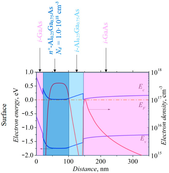
Figure 1.
Cross-section of modulation-doped semiconductor structure with energy band diagram (blue lines) and distribution of electron density (red lines) in the structure.
For the experiments, two types of bow-tie diodes were fabricated: (1) diodes with metallic contacts within the semiconductor mesa structure (hereafter referred to as WL diodes), and (2) diodes with metallic ohmic contacts extending beyond the mesa structure (hereafter referred to as BL diodes). Additionally, based on the geometric shape of the semiconductor mesa, both symmetric and asymmetric bow-tie diodes were manufactured and studied, hereafter referred to as SD and AD diodes, respectively. The four diode types are illustrated in Figure 2: asymmetric and symmetric bow-tie diodes with contacts within the mesa structure (WLAD and WLSD, respectively, in Figure 2a), and asymmetric and symmetric bow-tie diodes with contacts extending beyond the mesa structure (BLAD and BLSD, respectively, in Figure 2b).
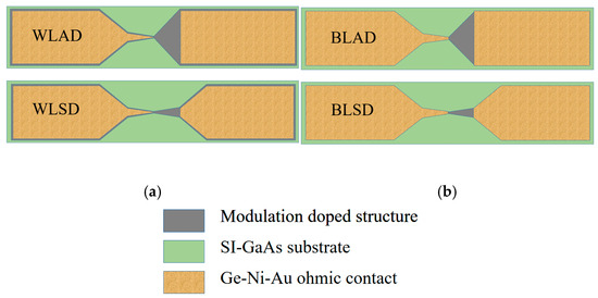
Figure 2.
Schematic view of asymmetric and symmetric bow-tie diodes with ohmic contacts within (a) and beyond (b) the mesa area.
We have doubled the nomenclature of the studied diodes because each of the aforementioned types was fabricated with the diode’s longitudinal axis aligned along either the primary or secondary flat cuts of the (100) GaAs substrate [47] (hereafter referred to as PF and SF diodes, respectively). As the voltage sensitivity of bow-tie diodes depends on the neck width d, each diode was fabricated with a neck width of 1, 2, or 3 μm. Micrographs of the diodes with d = 3 μm are shown in Figure 3.
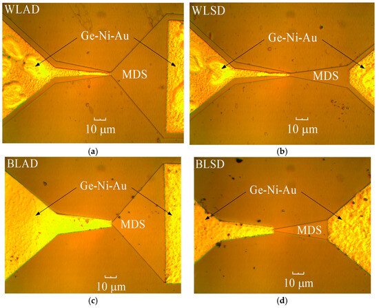
Figure 3.
Micrographs of the bow-tie diodes: (a) asymmetric WLAD with metallic contacts within the semiconductor mesa-structure; (b) symmetric WLSD with metallic contacts within the mesa-structure; (c) asymmetric BLAD with metallic contacts beyond the edges of the mesa; (d) symmetric BLSD with metallic contacts beyond the edges of the mesa. The abbreviation MDS stands for modulation-doped semiconductor structure.
The planar bow-tie diode fabrication process is described in detail in [48]. Detection experiments were conducted using a Cascade Microtech (FormFactor, Inc., Livermore, CA, USA) high-frequency probe station, and ACP40-A-GS-250 probes were used to connect the diodes to the millimeter wave sweep generator G4403E (Elmika Ltd., Vilnius, Lithuania) and to the detected voltage measuring device. The separation of the detected dc voltage signal from the microwave signal was performed using an SHF BT45 broadband bias tee. I–V characteristics were measured using a Suss MicroTec probe station EP6 with dc probes (FormFactor, Inc., Livermore, CA, USA) and Agilent E5270B precision Measurement equipment (Agilent Technologies, Inc., Santa Clara, CA, USA). Electrical parameters were determined both in the dark and under illumination from a broadband photo-lamp Eiko EKE21V150W (color temperature 3240K), following the measurement techniques detailed in [46,47]. The spectrum of the photo-lamp is shown in Figure A1 of Appendix A. During the diode fabrication, corresponding test structures were also produced to determine the sheet resistance and contact resistivity of the semiconductor structures. These parameters were obtained using the transmission line model, in which electrical resistance was measured between ohmic contacts spaced at different distances on rectangular semiconductor mesas [49].
3. Results
In this section, we present the measurement results for voltage sensitivity, electrical resistance, I–V characteristic asymmetry, and the nonlinearity coefficient of the investigated bow-tie diodes. Experimental values of these parameters are compared with their corresponding theoretical predictions in the subsections below.
3.1. Voltage Sensitivity
Recall that the voltage sensitivity of a microwave diode is defined as the ratio of the voltage detected by the diode to the power of the microwave radiation supplied to the probe head. The voltage sensitivity of the 11 × 6 bow-tie diode arrays is presented in Appendix B. Maps of the voltage sensitivity for WLPF and WLSF diodes are shown in Figure A2, while maps for BLPF and BLSF diodes are presented in Figure A3. A preliminary inspection of the maps reveals only slight differences between PF and SF diodes, with more pronounced differences observed for BL diodes. Figure 4 illustrates the dependence of the mean voltage sensitivity of the investigated bow-tie diodes on the neck width, both in the dark and under illumination.
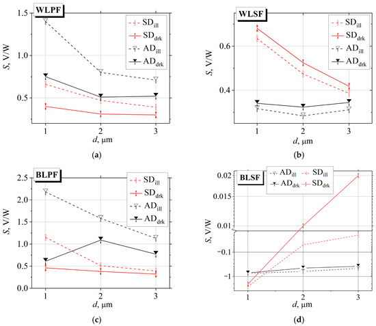
Figure 4.
Dependence of voltage sensitivity of the bow-tie diodes on the neck width in the dark and under illumination: (a) diodes with metallic contacts within the edges of the mesa structure, with the longitudinal axis aligned along the substrate’s primary flat cut (WLPF); (b) diodes with metallic contacts within the edges of the mesa structure, with the longitudinal axis aligned along the substrate’s secondary flat cut (WLSF); (c) diodes with metallic contacts extending beyond the mesa structure, with the longitudinal axis aligned along the substrate’s primary flat cut (BLPF); (d) diodes with metallic contacts extending beyond the mesa structure, with the longitudinal axis aligned along the substrate’s secondary flat cut (BLSF).
First, it should be noted that the polarity of the detected voltage for all diodes, except BLSF diodes, corresponds to the sign of the hot-electron thermoelectric EMF, with the positive potential measured on the left metal contact (see Figure 3). Illumination of both WL and BL diodes with their longitudinal axis aligned along the primary flat cut increases the voltage sensitivity (Figure 4a,c). In contrast, WLSF diodes, with the longitudinal axis parallel to the secondary flat cut, exhibit higher sensitivity to microwave radiation in the dark (Figure 4b). Additionally, symmetric BLSF diodes in the dark with wider necks are more sensitive to photo-lamp illumination. For these diodes, the polarity of the detected voltage reverses when the neck width d is reduced to 1 µm or when WLSF diodes are illuminated (Figure 4d). Consequently, symmetric BLSF diodes with d = 1 µm, as well as all asymmetric BLSF diodes, detect voltages with a polarity opposite to that of the hot-electron TEMF. Asymmetric BLSF diodes exhibit lower sensitivity to illumination. Another characteristic of SF diodes, both WL and BL, is that symmetric diodes are more sensitive to microwave radiation than asymmetric ones, in contrast to the behavior observed for PF diodes.
A comparison of the voltage sensitivity of WL and BL bow-tie diodes shows that symmetric diodes (SD2 and SD3; here, numbers stand for the neck width in micrometers) with their longitudinal axis parallel to the primary flat cut exhibit approximately the same sensitivity. In contrast, the sensitivity of asymmetric PF diodes (ADPF) with neck widths of 2 and 3 μm is roughly twice as high for BL diodes, as shown in Figure 5a. Notably, for SD1 and AD1 bow-tie diodes with PF orientation, there is no significant difference between WL and BL diodes in the dark, whereas under illumination, the voltage sensitivity of BL diodes is approximately 1.5 times higher than that of WL diodes.
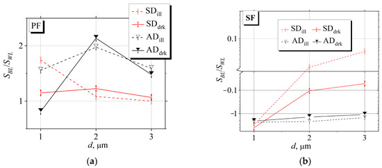
Figure 5.
The ratio of voltage sensitivity of BL and WL bow-tie diodes: (a) PF diodes with their longitudinal axis oriented along the primary flat cut; (b) SF diodes with longitudinal axis oriented along the secondary flat cut.
The situation is more complex when comparing WL and BL diodes oriented along the secondary flat cut. The absolute voltage sensitivity of asymmetric BLSF diodes exceeds that of WLSF diodes by a factor of 1.5–2.5, depending on illumination and diode neck width. It should also be noted that the detected voltage polarities of these diodes are opposite, as shown in Figure 4b,d. The absolute sensitivity of SD1 SF diodes is 3–4 times higher than that of PF diodes, with the polarities of the detected voltages also opposite. As the neck width of symmetric SF diodes increases, the sensitivity of WL diodes becomes significantly higher than that of BL diodes; depending on illumination conditions and neck width, WL SD diodes can be 10 to 40 times more sensitive to microwave radiation than the corresponding BL diodes.
The ambiguous and, in some cases, contradictory voltage sensitivity values observed for various bow-tie diodes necessitate a comparison of experimental results with theoretical predictions. Assuming that the voltage detected by a bow-tie diode arises from the thermoelectric EMF of hot electrons, the diode’s voltage sensitivity can be expressed as follows [45]:
where is the detected voltage; and are the incident microwave power on the diode and the power absorbed by the diode, respectively; is the sheet resistance of the semiconductor structure; is the low-field electron mobility; denote the widening angle of the diode’s active region and the widths of its widest and narrowest sections, respectively. is a factor that depends on the microwave frequency , electron momentum relaxation time , electron energy relaxation time and Maxwell relaxation time :
here, s is the exponent describing the dependence of electron momentum relaxation time τi on the electron energy .
Ratios of the experimentally measured voltage sensitivity to the values calculated using Equation (1) for the investigated bow-tie diodes are presented in Figure 6.
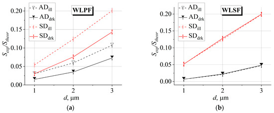
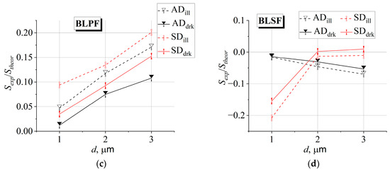
Figure 6.
Dependence of the ratio of experimental (measured in the dark and under illumination) to theoretical voltage sensitivity of the investigated bow-tie diodes on neck width d: (a) WLPF diodes; (b) WLSF diodes; (c) BLPF diodes; (d) BLSF diodes.
Since the useful fraction of incident microwave power, which generates the detected voltage , is actually unknown, the theoretical voltage sensitivity values presented in Figure 6 were calculated under the assumption that the diode absorbs all incident on the diode power , i.e., . Therefore, we can equate the ratio to the ratio and formally call it the microwave radiation absorption coefficient K, which represents the fraction of the microwave power absorbed by the diode that generates the voltage detected by the diode. In this way, it is possible to experimentally estimate the MW radiation power absorbed by the diode, which is used to detect the voltage , formally stating that the polarity of the detected voltage corresponds to that of the hot-electron thermoelectric EMF, specifically, for positive detected voltage values, assuming that the detected voltage arises solely from the hot-electron TEMF. Table A1 in Appendix C presents the values of the estimated absorption coefficient in percentages obtained from the dependencies in Figure 6 for the WLPF, WLSF, and BLPF bow-tie diodes. A noteworthy feature of the experimental and theoretical voltage sensitivity of bow-tie diodes is the differing dependence of their ratio on illumination. For WLPF and BLPF diodes, this ratio varies with illumination and is higher for symmetric diodes, whereas for WLSF diodes, the ratio is independent of illumination and remains higher for symmetric diodes. In terms of microwave radiation absorption, symmetric bow-tie diodes exhibit a higher absorption coefficient, which appears inconsistent with their higher electrical resistance, as will be discussed in the next subsection. Since diodes with higher resistance are less well-matched to the microwave transmission line by a reduced fraction of absorbed microwave power, we proceed to analyze the electrical resistance of the studied diodes in weak electric fields.
3.2. Electrical Resistance
A distinctive feature of the I–V characteristics of bow-tie diodes is their quasi-linearity. Figure 7 presents the I–V characteristics of four types of bow-tie AD1 (neck width equals 1 μm) diodes measured in the dark. From this representation, conclusions regarding the nonlinearity and asymmetry of the I–Vs can be drawn only with considerable caution. Therefore, in Appendix D, we present the dependence of the percentage change in resistance on the applied voltage for all studied diodes, relative to their resistance at zero electric field.
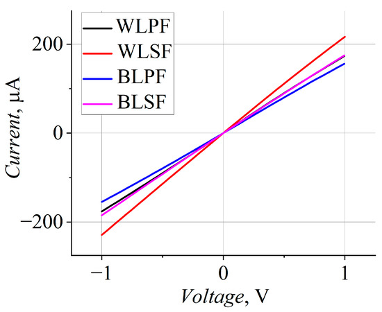
Figure 7.
I–V characteristics of the studied AD1 bow-tie diodes in the dark.
As shown in Figure A3, the I–V characteristics presented in Figure 7 are indeed nonlinear and asymmetric with respect to the applied voltage. The character of this nonlinearity and asymmetry differs among the four diode types: WLPF, WLSF, BLPF, and BLSF. The dependencies in Figure A3 further indicate that the I–V characteristics are strongly influenced by the diodes’ orientation relative to the crystallographic axes. However, the design of the diode’s ohmic contacts also affects these characteristics. Specifically, for WLPF diodes, the electrical resistance increases with increasing voltage for both polarities. In contrast, for illuminated BLPF asymmetric diodes (ADs) in the forward direction (the negative voltage is applied to the left contact of the bow-tie diode, see Figure 3), a slight decrease in resistance is observed initially, followed by an increase as the applied voltage continues to rise. More pronounced differences in I–V characteristics are observed for SF diodes. For BLSF asymmetric diodes, the resistance-voltage dependence shows little variation between dark and illuminated conditions: resistance increases with voltage for positive polarity and for negative polarity at low voltages. In contrast, WLSF diodes exhibit a decrease in resistance under negative bias in the dark, while under illumination, their resistance increases across the entire applied voltage range. These distinctions in the voltage dependence of bow-tie diode resistance will become clearer in the next section, where the asymmetry of the I–V characteristics is examined.
To further clarify the differences between WL and BL diodes, we examine their resistances in the weak electric field regime. Using the data presented in the legends of Figure A3, the low-field electrical resistances of WL and BL diodes were compared, as shown in Figure 8. In all cases, BL diodes exhibit higher low-field resistance than their WL counterparts. This difference is most pronounced for symmetric PF diodes and for symmetric SF diodes with a neck width of 1 µm, whereas for symmetric diodes with wider necks and for all asymmetric diodes, the resistance ratio fluctuates around ~1.2. For PF diodes, the ratio is larger for illuminated devices as well as for those with a narrower neck. The situation is somewhat different for SF diodes. The resistance of symmetric SF diodes is independent of illumination, whereas the behavior of asymmetric SF diodes is less straightforward. As shown in Figure 8b, the ratio to for asymmetric SF diodes is nearly independent of neck width; however, under illumination, diodes with a 1 μm neck exhibit a smaller ratio compared to those with wider necks.
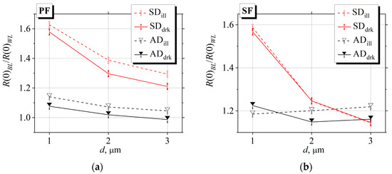
Figure 8.
The ratio of low field electrical resistance of BL and WL bow-tie diodes: (a) PF diodes in which the longitudinal axis is oriented along the primary flat cut; (b) SF diodes in which the longitudinal axis is oriented along the secondary flat cut.
We now turn to a comparison of the experimental and theoretical low-field electrical resistance of bow-tie diodes. The theoretical resistance is calculated as the sum of the geometric resistance of the bow-tie–shaped semiconductor structure and the parasitic resistance of the diode contacts:
where is the contact resistivity. The sheet resistance and the contact resistivity of the investigated bow-tie diodes are presented in Table 1.

Table 1.
Sheet resistance and contact resistivity of the investigated bow-tie diodes.
Figure 9 presents the dependence of the ratio between the experimentally measured low-field resistance and the values calculated using Equation (3) on the neck width of the investigated bow-tie diodes.
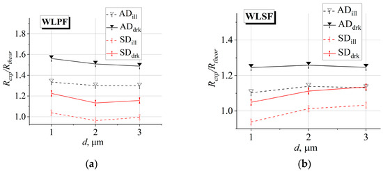
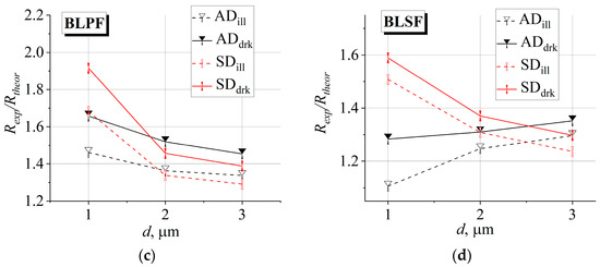
Figure 9.
Ratio of experimental to theoretical low-field resistance versus neck width d for bow-tie diodes in the dark and under illumination: (a) WLPF diodes; (b) WLSF diodes; (c) BLPF diodes; (d) BLSF diodes.
Comparison of experimental and theoretical electrical resistance values of the studied diodes shows that the experimental values are consistently higher for all diodes. A common feature is that the discrepancy between experimental and theoretical resistances is greater in the dark than under illumination. Differences are observed when comparing WL and BL diodes, as well as PF and SF diodes. Specifically, the experimental resistance of BL diodes deviates more from the theoretical values than that of WL diodes. Similarly, the resistances of SF diodes are closer to the theoretical predictions than those of PF diodes, reflecting the influence of the orientation of the diode relative to the crystallographic axes. The dependence of the ratio of experimental to theoretical resistances on the neck width varies among different diode types. For diodes with their longitudinal axis aligned along the primary flat cut, the ratio Rexp/Rtheor decreases slightly as the neck widens, with this trend being more pronounced for BL diodes. Larger differences between experimental and theoretical resistances are observed for diodes oriented along the secondary flat cut. For WLSF asymmetric diodes, the resistance ratio is nearly independent of neck width, whereas for BLSF asymmetric diodes, the ratio increases with increasing neck width. An even more pronounced behavior is seen for symmetric SF diodes: for WL diodes, Rexp/Rtheor increases with the neck width, while for BL diodes it decreases.
3.3. Asymmetry of I–V Characteristics
It is well known that the asymmetry of the current–voltage characteristic of a microwave diode with an n-n+ junction (denoted as asym) is related to the diode’s sensitivity , provided that the relaxation of the average energy of hot electrons can be neglected [45]:
where and denote the low-field electrical resistance of the diode measured under forward and reverse bias, respectively. In this section, we examine the asymmetry of the I–V characteristics of the studied diodes and compare it with the theoretical values calculated from the phenomenological expression [45]:
The experimental dependence of the I–V characteristic asymmetry on the neck width of the bow-tie diodes is shown in Figure 10.
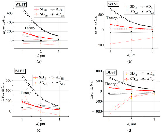
Figure 10.
Experimental and theoretical dependences of the I–V characteristics asymmetry on the neck width of bow-tie diodes: (a) WLPF; (b) WLSF; (c) BLPF; (d) BLSF. Solid symbols with thin lines represent experimental data in the dark, and hollow symbols with dashed thin lines represent experimental data under illumination. Thicker solid lines indicate theoretical predictions in the dark, and dotted lines correspond to theoretical predictions under illumination. Black lines represent asymmetric AD diodes, and red lines denote symmetric SD diodes.
The figure also shows the theoretical dependences of I–V asymmetry on the neck width of the bow-tie diodes, calculated using Equation (5). First, it should be noted that there is a difference between the experimental and theoretical I–V asymmetry for diodes in the dark and under illumination. Theoretical predictions indicate that the I–V asymmetry of bow-tie diodes is larger in the dark than under illumination, in contrast to the experimental results, except for BLPF symmetric diodes with a wider neck (see Figure 10c). Another notable difference between theoretical and experimental I–V asymmetries is that, for most diodes, the sign of the experimentally measured asymmetry aligns with the theoretical prediction under illumination. Exceptions are the BL bow-tie diodes: the I–V asymmetry of BLSF diodes, both in the dark and under illumination, is opposite to the theoretical prediction (see Figure 10d). In contrast, BLPF diodes generally exhibit I–V asymmetry consistent with theoretical calculations, except for illuminated symmetric diodes with wider necks (see Figure 10c). Regarding the dependence of I–V asymmetry on the neck width of bow-tie diodes, only illuminated WLPF and WLSF diodes, both SD and AD, as well as asymmetric BLPF diodes, exhibit a decrease in asymmetry with increasing neck width. However, this decrease occurs more gradually than predicted by theory.
To summarize the comparison of I–V asymmetry among bow-tie diodes of various designs, Figure 11 presents the dependence of the I–V asymmetry ratio between BL and WL diodes on the neck width.
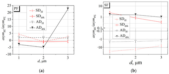
Figure 11.
Ratios of I–V asymmetry for BL and WL bow-tie diodes: (a) PF diodes with the longitudinal axis oriented along the primary flat cut; (b) SF diodes with longitudinal axis oriented along the secondary flat cut.
From the dependencies shown in Figure 11, it is evident that a meaningful comparison of I–V asymmetry can be made only for illuminated asymmetric PF diodes, for which the asymmetry of BL diodes is 1.5–2 times greater than that of WL diodes. A similar trend might be expected for asymmetric and symmetric SF diodes in the dark, where the ratio is close to unity (Figure 11b); however, the I–V asymmetry of these diodes exhibits the opposite sign relative to theoretical predictions (Figure 10b,d). The ratio is negative for illuminated SF diodes (Figure 11b) and for PF diodes in the dark (except for AD diodes in the dark, Figure 11a), indicating opposite signs of I–V asymmetry between WL and BL diodes. Although the I–V asymmetry in the dark for WLPF and BLPF AD3 diodes aligns with theory, the magnitude of this asymmetry for BL diodes is an order of magnitude greater than that for WL AD3 diodes.
3.4. Nonlinearity Coefficient of I–V Characteristics
A phenomenological parameter characterizing hot-electron transport in semiconductors is the nonlinearity coefficient of the I–V characteristic, which quantifies the deviation of the I–V relationship from linear behavior [50]:
where denotes the current density, is the low-field electrical conductivity, and is the electric field strength. The strongest electric field in a bow-tie diode occurs at its narrowest point, i.e., the neck. Accordingly, for a voltage applied across the diode contacts, the current through the bow-tie diode can be expressed as follows [45]:
By approximating the experimental I–V characteristics of bow-tie diodes using Equation (7) and treating the thickness of the diode active region and the nonlinearity coefficient as fitting parameters, we obtain experimental values for both and . The active-region thickness for all studied diodes ranged from 8 to 9 nm, consistent with the actual thickness of the 2DEG layer in the modulation-doped structure [51]. In contrast, the values varied among the diodes and depended on whether the diode was measured in the dark or under illumination. The results of the approximation are presented in Figure 12.
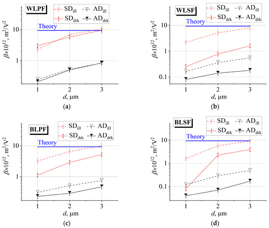
Figure 12.
Dependence of the approximated nonlinearity coefficient of the I–V characteristics of the investigated bow-tie diodes on neck width : (a) WLPF; (b) WLSF; (c) BLPF; (d) BLSF. Solid symbols represent experimental data in the dark, and hollow symbols represent data under illumination. Black symbols denote asymmetric diodes, while red symbols denote symmetric diodes. The blue line indicates the theoretical value of the nonlinearity coefficient.
As a material parameter, the nonlinearity coefficient can be expressed in terms of other semiconductor properties, such as the electron mobility , electron energy relaxation time , and the exponent describing the dependence of electron momentum relaxation time on electron energy [4]:
Assuming that electron scattering is dominated by optical phonons ( = 1 [6]) and taking = 0.237 cm2/(V·s) and = 1.5 ps [4], the value of the nonlinearity coefficient calculated according to Equation (8) is 9.3 m2/V2. This theoretical value is represented by the blue line in the graphs of Figure 12.
Several trends are evident from the relationships presented in Figure 12. First, the approximated nonlinearity coefficient increases with increasing neck width of the bow-tie diodes. Second, symmetric diodes exhibit higher nonlinearity coefficients than asymmetric diodes. Third, illuminated diodes generally show larger nonlinearity coefficients than those measured in the dark. However, the effect of illumination varies among diode types; for instance, WLPF diodes are the least sensitive to illumination in this regard. To examine the influence of illumination on I–V nonlinearity in more detail, Figure 13 presents the dependence of the ratio of nonlinearity coefficients under illumination to those in the dark as a function of the diode neck width.
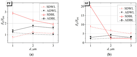
Figure 13.
Ratios of the I–V nonlinearity coefficient for bow-tie diodes under illumination to those in the dark: (a) PF diodes with the longitudinal axis oriented along the primary flat cut; (b) SF diodes in which the longitudinal axis is oriented along the secondary flat cut.
As shown in Figure 13a, for WL diodes, both AD and SD, with their longitudinal axis parallel to the primary flat cut, the I–V nonlinearity coefficient is largely independent of illumination. For illuminated BLPF asymmetric bow-tie diodes, is approximately 1.5 times higher than in the dark, with only a slight dependence on neck width d. For symmetrical BLPF diodes, the ratio ranges from 2 to 3, being higher for diodes with narrower necks. A different behavior is observed for diodes oriented along the secondary flat cut (Figure 13b). First, the ratio is higher than for diodes oriented along the primary flat cut. Second, for illuminated symmetric WLSF diodes, is 5–9 times higher than in the dark, with the ratio increasing as the neck width decreases. Asymmetric WLSF bow-tie diodes are less sensitive to illumination, with ≈ 2.5 independent of neck width. Asymmetric BLSF diodes exhibit similar behavior, with slight sensitivity to illumination, also independent of neck width. Symmetric BLSF diodes are an exception: for SD1 diodes, is 20 times higher than in the dark. To conclude the discussion on nonlinearity coefficients, Figure 14 presents a comparison between WL and BL bow-tie diode designs.
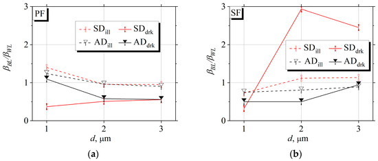
Figure 14.
Ratios of the I–V nonlinearity coefficient for BL and WL bow-tie diodes: (a) PF diodes with the longitudinal axis oriented along the primary flat cut; (b) SF diodes with the longitudinal axis oriented along the secondary flat cut.
A general feature of bow-tie diodes oriented along both the primary and secondary flat cuts is that the I–V nonlinearity coefficients of WL diodes are generally higher than those of BL diodes, with exceptions for PF diodes with a 1 µm neck width (Figure 14a) and SF symmetric diodes with wider necks (Figure 14b). When comparing BL and WL diodes, it is important to consider symmetric diodes in the dark. For PF-oriented SD diodes in the dark, is approximately twice that of WL diodes, whereas for SF-oriented diodes with wider necks, the nonlinearity coefficient of BL diodes is 2.5–3 times higher than that of WL diodes; in contrast, the BL SD1 diode exhibits a value roughly half that of the WL SD1 diode. It is also notable that the ratio exhibits a weak dependence on neck width: for PF-oriented diodes, this ratio decreases as the neck widens (Figure 14a), while for SF-oriented diodes, it decreases with decreasing neck width (Figure 14b). This trend does not apply to the PF SD diodes in the dark mentioned above (Figure 14a).
4. Discussion
The voltage sensitivity results for the investigated bow-tie diodes indicate that, for most diodes, the detected voltage originates from electron heating by the microwave electric field, as evidenced by the polarity of the detected voltage matching the thermoelectric emf of hot carriers [52]. However, while the detected voltage in WLPF, WLSF, and BLPF diodes can be attributed to the hot-carrier thermoelectric effect, BLSF diodes exhibit a detected voltage with polarity opposite to that of the hot-carrier emf, except for diodes with wider necks measured in the dark. When comparing the experimental voltage sensitivity with predictions from phenomenological theory, a key challenge arises in estimating the useful fraction of microwave radiation absorbed by the bow-tie diode, which allows a diode to detect voltage . This absorption depends on multiple factors, including conduction losses, dielectric polarization, and multiple reflections within the semiconductor material [53]. Consequently, by comparing experimental and theoretical voltage sensitivities, we can estimate the fraction of microwave power delivered by the high-frequency probe that contributes to the voltage detected by the bow-tie diode, assuming that this voltage originates from the hot carrier thermoelectric emf. Analysis of the absorption coefficients of bow-tie diodes presented in Table A1 (Appendix C) reveals that symmetric diodes exhibit higher absorption than asymmetric ones. This observation appears to contradict the established principle that a diode absorbs microwave radiation more efficiently when its impedance closely matches the characteristic impedance of the transmission line, i.e., when the diode is well-matched to the line [54]. It is noteworthy that this discrepancy is particularly pronounced for WLSF diodes, where SD1 diodes absorb microwave radiation approximately 7.5 times more efficiently than AD1 diodes. Moreover, the ratio of absorption coefficients for SD and AD diodes decreases with increasing neck width for WLSF diodes, whereas for WLPF diodes, this ratio remains essentially constant across all neck widths. PF and SF diodes also exhibit different absorption behavior under illumination and in the dark: PF diodes absorb microwave radiation more effectively when illuminated, whereas the absorption coefficient of WLSF diodes is largely independent of illumination. Consistent with phenomenological theory, the voltage sensitivity of asymmetric PF diodes exceeds that of symmetric ones; however, for SF diodes, the opposite trend is observed, with SD diodes exhibiting higher sensitivity than AD diodes, in contradiction to the theoretical expectation (Figure 4). Furthermore, for BLSF symmetric diodes in the dark, the detected voltage reverses polarity as the neck narrows. The polarity of the detected voltage for illuminated SD diodes and for AD diodes, both in the dark and under illumination, corresponds to that of a Schottky diode, as shown in Figure 4d. Regarding the comparison of bow-tie diode designs in terms of voltage sensitivity, it is important to consider the dependence of BL and WL diode sensitivity on neck width (Figure 5). For SD diodes with wider necks, the sensitivity is nearly identical for both BL and WL diodes, whereas AD BL diodes exhibit a sensitivity 1.5–2 times higher than that of WL diodes, both in the dark and under illumination. For diodes with a 1 µm neck, voltage sensitivity in the dark shows little difference between BL and WL diodes, while under illumination, BL diodes display a 1.5-fold higher sensitivity than WL diodes. This trend is observed for diodes both in the dark and under illumination. For bow-tie diodes with a 1 µm neck, voltage sensitivity in the dark shows little difference between BL and WL diodes, whereas under illumination, BL diodes exhibit a sensitivity approximately 1.5 times higher than that of WL diodes. The complex and sometimes contradictory dependence of voltage sensitivity on diode design, crystallographic orientation, illumination, geometry, and neck width suggests that the detected voltage is not solely determined by the thermoelectric emf of hot carriers. As noted in [45], the electrical behavior of bow-tie diodes is also influenced by charge-carrier trapping phenomena in modulation-doped semiconductor structures with varying configurations. Therefore, we next analyze the low-frequency electrical properties of the studied diodes, beginning with their resistance in weak electric fields.
Although the electrical resistance of bow-tie diodes is primarily determined by their orientation relative to the crystallographic axes (Figure A4, Appendix D), the diode design also significantly influences the I–V characteristics. This effect is particularly pronounced for diodes with their longitudinal axis aligned along the secondary flat cut (SF diodes). A comparison of voltage sensitivity and electrical resistance for BL and WL bow-tie diodes (Figure 5 and Figure 8) reveals no straightforward correlation between these parameters. For PF-oriented SD diodes with wider necks, voltage sensitivity is nearly identical for BL and WL diodes, whereas the electrical resistance of BL diodes is approximately 1.5 times higher. Conversely, for the corresponding AD diodes, the voltage sensitivity of BL diodes is roughly twice that of WL diodes, while their electrical resistance shows little difference. A weak correlation between voltage sensitivity and electrical resistance is observed for SF-oriented diodes. The qualitatively and quantitatively distinct dependence of the ratio on the diode neck width (Figure 5b) is partially reflected in the dependence on , as evidenced by the relatively weak influence of illumination on this ratio (Figure 8b). Comparison of experimental and theoretical electrical resistances reveals that the measured values consistently exceed those calculated using Equation (3), as shown in Figure 9. Notably, the theoretical calculations include the contribution of contact resistance; thus, the observed ratio cannot be attributed solely to contact resistance effects. The dependence of this ratio on both the bow-tie diode design and the orientation relative to the crystallographic axes suggests that additional factors affecting the diode resistance were not accounted for in the theoretical calculations. As is well known, the resistance of a bow-tie diode is determined by the resistivity of the material forming the diode, which depends on both electron mobility and electron density. Given that the electron mobility is expected to be similar across our samples, which are fabricated from the same material, the discrepancy between theoretical and experimental resistance values is likely attributable to variations in electron density as carriers traverse the diode under applied voltage, with electrons being captured at defect centers. Such centers include DX centers in the AlGaAs barrier [55], interface-related defects between the GaAs and AlGaAs layers [56], and deep surface levels [57,58].
The ambiguous and largely contradictory results of the I–V asymmetry studies of bow-tie diodes (Figure 10), when compared with the experimental voltage sensitivity values (Figure 4), indicate only a weak correlation between I–V asymmetry and voltage sensitivity for PF-oriented diodes, while no such correlation exists for SF-oriented diodes. A comparison of voltage sensitivity and I–V asymmetry for BL and WL diodes (Figure 5 and Figure 11) reveals no clear correspondence between these parameters. This discrepancy can be explained by considering that the I–V characteristics of bow-tie diodes are influenced by slow electron capture into deep energy levels [59], which do not significantly affect the diode’s detection properties, thereby accounting for the lack of correlation between voltage sensitivity and I–V asymmetry.
When analyzing the nonlinearity coefficient of bow-tie diode I–V characteristics, the discrepancy between the experimentally approximated values and the theoretical estimates (Figure 12) should not be overemphasized. The theoretical estimates based on Equation (8) are inherently approximate, as several parameters in the expression, such as the electron energy relaxation time and the electron scattering mechanism, which determines the parameter , are not precisely known. Of greater significance is the dependence of on the diode design (BL versus WL), diode geometry (SD versus AD), and the width of the diode neck, i.e., the region where the electric field is strongest. This dependence on diode shape and neck width implies that the nonlinearity coefficient itself is a function of the electric field strength , which is determined by the geometry of the bow-tie diode:
Since is theoretically determined by the electron scattering mechanism and electron energy relaxation, this alone cannot account for its dependence on the geometry of bow-tie diodes. Similar to the discrepancy observed between experimental and theoretical low-field electrical resistance, this behavior can be explained by considering that the electron density varies as electrons move under the applied voltage . In this case, the variation in electron density is also influenced by the local electric field strength . The effect of illumination on the nonlinearity coefficient of the I–V characteristic is also noteworthy: while increases under illumination for WLSF and BL diodes, the nonlinearity coefficient of WLPF diodes remains nearly independent of illumination (Figure 12). The differing responses of WLPF and WLSF diodes to illumination can be attributed to variations in electron motion along different crystallographic axes [3]. A natural question arises as to why the nonlinearity coefficient of BL diodes is largely insensitive to illumination for both PF and SF orientations. This behavior may result from differences in how WL and BL diodes are illuminated: in WL diodes, the semiconductor regions not covered by metal are illuminated on both sides of the bow-tie diode neck, whereas in BL diodes, only the right side of the neck is illuminated, as illustrated in Figure 3. When comparing BL and WL bow-tie diodes, no significant difference in the nonlinearity coefficient is observed. A weak, but distinct, dependence of the ratio on the diode neck width can be noted for PF and SF orientations. Notably, for SD diodes in the dark, this ratio increases with increasing neck width , and for SF diodes, this dependence is even more pronounced, as shown in Figure 14.
5. Conclusions
Detailed studies of bow-tie diodes fabricated from modulation-doped semiconductor structures with wide spacers enable a comprehensive generalization of their detection properties, taking into account the diode geometry and contact design, orientation relative to the crystallographic axes, dimensions of the active region, and illumination conditions:
- ➢
- The polarity of the voltage detected by bow-tie diodes corresponds to the thermoelectric electromotive force of hot electrons when the diode’s longitudinal axis is aligned with the primary flat cut of the GaAs (100) substrate, independent of the metal contact geometry, and also for diodes with metal contacts confined to the semiconductor mesa structure when their longitudinal axis is parallel to the secondary flat cut of the substrate.
- ➢
- For diodes with metal contacts extending beyond the semiconductor mesa structure, the polarity of the detected voltage depends on both the diode geometry and illumination conditions: only symmetrical diodes with a wider neck in the dark exhibit a detected voltage whose polarity matches that of the hot-electron thermoelectric emf.
- ➢
- White-light illumination affects diodes differently depending on their orientation relative to the crystallographic axes: diodes oriented along the secondary flat cut exhibit higher voltage sensitivity in the dark than under illumination, while the diodes oriented along the primary flat cut, on the contrary, exhibit higher voltage sensitivity under illumination.
- ➢
- The experimentally observed higher electrical resistances of bow-tie diodes compared to theoretical predictions can be attributed to electron capture at various trap centers as electrons traverse the diode under an applied voltage.
- ➢
- The weak or absent correlation between the voltage sensitivity of bow-tie diodes and the asymmetry of their I–V characteristics suggests that the I–V response is strongly influenced by electron capture into deep levels, which, owing to the slow dynamics of these processes, is minimally reflected in or largely decoupled from microwave detection.
- ➢
- The dependence of the I–V nonlinearity coefficient on both the geometry of the bow-tie diodes and the width of their necks supports the hypothesis that the electron density varies as electrons traverse the diode under the influence of the applied voltage.
- ➢
- Future studies of bow-tie diodes, aimed at further elucidating their microwave detection mechanism, will focus on a detailed analysis of electron capture into deep centers, employing diodes based on a variety of modulation-doped semiconductor structures.
Author Contributions
Conceptualization, A.S. and S.A.; methodology, A.S., S.A., M.A. and J.G.; simulations, A.S. and A.L.; microwave investigation, A.S., M.A. and A.L.; illumination experiments, A.Č.; writing—original draft preparation, A.S.; writing—review and editing, S.A., A.Č. and J.G.; visualization, A.S., A.Č. and J.G.; supervision, A.S.; project administration, J.G. All authors have read and agreed to the published version of the manuscript.
Funding
This research received no external funding.
Data Availability Statement
The original contributions presented in the study are included in the article; further inquiries can be directed to the corresponding author.
Acknowledgments
The authors acknowledge Hadas Shtrikman from Braun Center for Submicron Research, at the Weizmann Institute of Science, Rehovot, Israel, for MBE-grown structures, which were used for sample preparation, as well as Angelė Steikūnienė and Gytis Steikūnas, for their assistance in sample preparation.
Conflicts of Interest
The authors declare no conflicts of interest.
Abbreviations
The following abbreviations are used in this manuscript:
| 2DEG | Two-dimensional electron gas |
| AD | Asymmetric diode |
| AD1, AD2, AD3 | Asymmetric diodes with neck width 1, 2, 3 μm |
| BL | Beyond limits |
| BLPF | Beyond limits, primary flat |
| BLSF | Beyond limits, secondary flat |
| CMOS | Complementary metal oxide semiconductor |
| EIW | Electromagnetic induced well |
| FET | Field-effect transistor |
| FIR | Far infrared radiation |
| FPAs | Focal plane arrays |
| GN | Graphite nanosheet |
| HEMT | High electron mobility transistor |
| MBE | Molecular beam epitaxy |
| MDS | Modulation-doped semiconductor |
| MEMS | Micro-electro-mechanical systems |
| MOSFET | Metal oxide semiconductor field-effect transistor |
| MW | Microwave |
| PF | Primary flat |
| SD | Symmetric diode |
| SD1, SD2, SD3 | Symmetric diodes with neck width 1, 2, 3 μm |
| SF | Secondary flat |
| SOI | Silicon on insulator |
| SSD | Self-switching diode |
| TEMF | Thermoelectric electromotive force |
| WL | Within limits |
| WLPF | Within limits, primary flat |
| WLSF | Within limits, secondary flat |
Appendix A
Spectrum of broadband photo-lamp Eiko EKE21V150W.
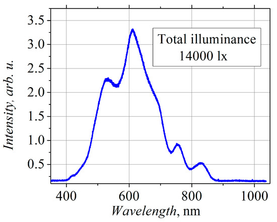
Figure A1.
Spectrum of photo-lamp [45].
Appendix B
Maps of the voltage sensitivity of the investigated bow-tie diodes.
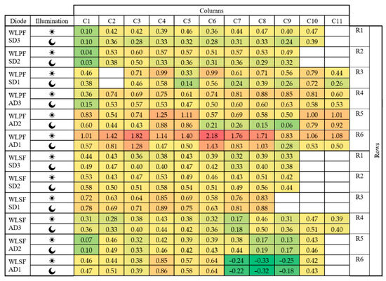
Figure A2.
Maps of voltage sensitivity (V/W) of WLPF and WLSF diodes. The sensitivity is measured in the dark ( ) and under illumination of photo-lamp (
 ).
).
 ) and under illumination of photo-lamp (
 ).
).
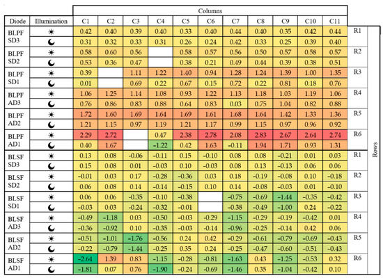
Figure A3.
Maps of voltage sensitivity (V/W) of BLPF and BLSF diodes. The sensitivity is measured in the dark ( ) and under illumination of photo-lamp (
 ).
).
 ) and under illumination of photo-lamp (
 ).
).
Appendix C
Absorption coefficients of microwave power derived from comparison of experimental and theoretical values of voltage sensitivity for WLPF, WLSF, and BLPF bow-tie diodes.

Table A1.
Absorption coefficients of microwave power of the investigated bow-tie diodes.
Table A1.
Absorption coefficients of microwave power of the investigated bow-tie diodes.
| d, µm | Absorption Coefficient of Microwave Power of Bow-Tie Diodes, % | |||||||||||
|---|---|---|---|---|---|---|---|---|---|---|---|---|
| WLPF | BLPF | WLSF | ||||||||||
| AD | SD | AD | SD | AD | SD | |||||||
| Drk | Ill | Drk | Ill | Drk | Ill | Drk | Ill | Drk | Ill | Drk | Ill | |
| 1 | 1.5 | 3.0 | 3.0 | 5.4 | 1.2 | 4.7 | 3.5 | 9.4 | 0.7 | 0.7 | 5.2 | 5.2 |
| 2 | 3.5 | 5.9 | 7.6 | 12.4 | 7.5 | 11.7 | 9.3 | 13.4 | 2.2 | 2.1 | 12.8 | 12.5 |
| 3 | 7.3 | 10.8 | 14.3 | 20.1 | 10.8 | 17.1 | 15.3 | 20.1 | 4.8 | 4.7 | 19.9 | 19.9 |
Appendix D
Dependence of the percentage change in resistance on voltage of all the studied diodes, relative to the resistance at zero electric field.
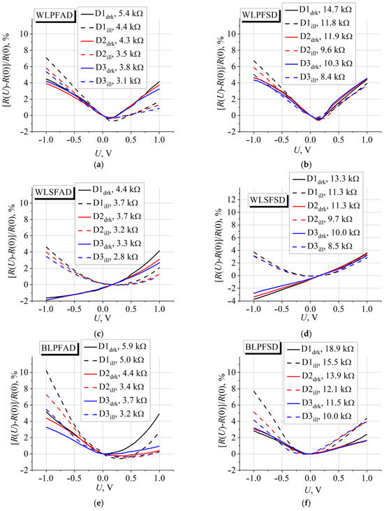
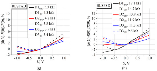
Figure A4.
R-V characteristics of the studied bow-tie diodes: WLPF asymmetric diodes (a); WLPF symmetric diodes (b); WLSF asymmetric diodes (c); WLSF symmetric diodes (d); BLPF asymmetric diodes (e); BLPF symmetric diodes (f); BLSF asymmetric diodes (g); BLSF symmetric diodes (h). In the legends: Dndrk and Dnill denote the curve assigned to the diode with a neck width n (in micrometers) in the dark and under illumination, respectively; numbers beside the notations indicate the resistance R (0) of the diode under zero applied voltage U.
References
- Sizov, F.F. Brief History of THz and IR Technologies. Semicond. Phys. Quantum Electron. Optoelectron. 2019, 22, 67–79. [Google Scholar] [CrossRef]
- Takida, Y.; Nawata, K.; Minamide, H. Security Screening System Based on Terahertz-Wave Spectroscopic Gas Detection. Opt. Express 2021, 29, 2529. [Google Scholar] [CrossRef]
- Tzydynzhapov, G.; Gusikhin, P.; Muravev, V.; Dremin, A.; Nefyodov, Y.; Kukushkin, I. New Real-Time Sub-Terahertz Security Body Scanner. J. Infrared Millim. Terahertz Waves 2020, 41, 632–641. [Google Scholar] [CrossRef]
- Amini, T.; Jahangiri, F.; Ameri, Z.; Hemmatian, M.A. A Review of Feasible Applications of THz Waves in Medical Diagnostics and Treatments. J. Lasers Med. Sci. 2021, 12, e92. [Google Scholar] [CrossRef]
- Wietzke, S.; Jansen, C.; Jördens, C.; Krumbholz, N.; Vieweg, N.; Scheller, M.; Shakfa, M.K.; Romeike, D.; Hochrein, T.; Mikulics, M.; et al. Industrial Applications of THz Systems. In Proceedings of the International Symposium on Photoelectronic Detection and Imaging 2009: Terahertz and High Energy Radiation Detection Technologies and Applications, Beijing, China, 3 July 2009; Zhang, X.-C., Ryan, J.M., Zhang, C., Tang, C., Eds.; SPIE: Bellingham, WA, USA, 2009; Volume 7385, p. 738506. [Google Scholar]
- Huang, Y.; Shen, Y.; Wang, J. From Terahertz Imaging to Terahertz Wireless Communications. Engineering 2023, 22, 106–124. [Google Scholar] [CrossRef]
- Sun, Y.; Wang, S.; Gong, Y. Terahertz’s Silent Revolution in Physics, Engineering, and Life Science: Beyond the Spectrum. Fundam. Res. 2025, 5, 1930–1932. [Google Scholar] [CrossRef]
- Siegel, P.H. THz Instruments for Space. IEEE Trans. Antennas Propag. 2007, 55, 2957–2965. [Google Scholar] [CrossRef]
- Castro-Camus, E.; Koch, M.; Mittleman, D.M. Recent Advances in Terahertz Imaging: 1999 to 2021. Appl. Phys. B 2022, 128, 12. [Google Scholar] [CrossRef]
- Slocum, D.M.; Slingerland, E.J.; Giles, R.H.; Goyette, T.M. Atmospheric Absorption of Terahertz Radiation and Water Vapor Continuum Effects. J. Quant. Spectrosc. Radiat. Transf. 2013, 127, 49–63. [Google Scholar] [CrossRef]
- Dyakonov, M.I.; Shur, M.S. Terahertz Sources and Systems, 1st ed.; Miles, R.E., Harrison, P., Lippens, D., Eds.; Kluwer Academic Publishers: Dordrecht, The Netherlands; Boston, MA, USA; London, UK, 2001. [Google Scholar]
- Yadav, R.; Ludwig, F.; Faridi, F.R.; Klopf, J.M.; Roskos, H.G.; Preu, S.; Penirschke, A. State-of-the-Art Room Temperature Operable Zero-Bias Schottky Diode-Based Terahertz Detector Up to 5.56 THz. Sensors 2023, 23, 3469. [Google Scholar] [CrossRef]
- Ito, H.; Ishibashi, T. InP/InGaAs Fermi-Level Managed Barrier Diode for Broadband and Low-Noise Terahertz-Wave Detection. Jpn. J. Appl. Phys. 2017, 56, 014101. [Google Scholar] [CrossRef]
- Dyakonov, M.; Shur, M. Detection, Mixing, and Frequency Multiplication of Terahertz Radiation by Two-Dimensional Electronic Fluid. IEEE Trans. Electron. Devices 1996, 43, 380–387. [Google Scholar] [CrossRef]
- Knap, W.; Deng, Y.; Rumyantsev, S.; Shur, M.S. Resonant Detection of Subterahertz and Terahertz Radiation by Plasma Waves in Submicron Field-Effect Transistors. Appl. Phys. Lett. 2002, 81, 4637–4639. [Google Scholar] [CrossRef]
- Coquillat, D.; Nadar, S.; Teppe, F.; Dyakonova, N.; Boubanga-Tombet, S.; Knap, W.; Nishimura, T.; Meziani, Y.M.; Otsuji, T.; Popov, V.V.; et al. Terahertz Detection in a Double-Grating-Gate Heterotransistor. J. Phys. Conf. Ser. 2009, 193, 012074. [Google Scholar] [CrossRef]
- Lisauskas, A.; Pfeiffer, U.; Öjefors, E.; Bolìvar, P.H.; Glaab, D.; Roskos, H.G. Rational Design of High-Responsivity Detectors of Terahertz Radiation Based on Distributed Self-Mixing in Silicon Field-Effect Transistors. J. Appl. Phys. 2009, 105, 114511. [Google Scholar] [CrossRef]
- Sensale-Rodriguez, B. Graphene-Insulator-Graphene Active Plasmonic Terahertz Devices. Appl. Phys. Lett. 2013, 103, 123109. [Google Scholar] [CrossRef]
- Spirito, D.; Coquillat, D.; De Bonis, S.L.; Lombardo, A.; Bruna, M.; Ferrari, A.C.; Pellegrini, V.; Tredicucci, A.; Knap, W.; Vitiello, M.S. High Performance Bilayer-Graphene Terahertz Detectors. Appl. Phys. Lett. 2014, 104. [Google Scholar] [CrossRef]
- Vitiello, M.S.; Viti, L.; Romeo, L.; Ercolani, D.; Scalari, G.; Faist, J.; Beltram, F.; Sorba, L.; Tredicucci, A. Semiconductor Nanowires for Highly Sensitive, Room-Temperature Detection of Terahertz Quantum Cascade Laser Emission. Appl. Phys. Lett. 2012, 100, 241101. [Google Scholar] [CrossRef]
- Vitiello, M.S.; Viti, L.; Coquillat, D.; Knap, W.; Ercolani, D.; Sorba, L. One Dimensional Semiconductor Nanostructures: An Effective Active-Material for Terahertz Detection. APL Mater. 2015, 3, 026104. [Google Scholar] [CrossRef]
- Marczewski, J.; Knap, W.; Tomaszewski, D.; Zaborowski, M.; Zagrajek, P. Silicon Junctionless Field Effect Transistors as Room Temperature Terahertz Detectors. J. Appl. Phys. 2015, 118, 104502. [Google Scholar] [CrossRef]
- Ahmad, Z.; Lisauskas, A.; Roskos, H.G.; O, K.K. Design and Demonstration of Antenna-Coupled Schottky Diodes in a Foundry Complementary Metal-Oxide Semiconductor Technology for Electronic Detection of Far-Infrared Radiation. J. Appl. Phys. 2019, 125, 194501. [Google Scholar] [CrossRef]
- Oda, N. Technology Trend in Real-Time, Uncooled Image Sensors for Sub-THz and THz Wave Detection. In Proceedings of the Micro- and Nanotechnology Sensors, Systems, and Applications VIII, Baltimore, MD, USA, 25 May 2016; George, T., Dutta, A.K., Islam, M.S., Eds.; SPIE: Bellingham, WA, USA, 2016; Volume 9836, p. 98362P. [Google Scholar]
- Zhang, Y.; Hosono, S.; Nagai, N.; Song, S.-H.; Hirakawa, K. Fast and Sensitive Bolometric Terahertz Detection at Room Temperature through Thermomechanical Transduction. J. Appl. Phys. 2019, 125, 151602. [Google Scholar] [CrossRef]
- Vicarelli, L.; Tredicucci, A.; Pitanti, A. Micromechanical Bolometers for Subterahertz Detection at Room Temperature. ACS Photonics 2022, 9, 360–367. [Google Scholar] [CrossRef] [PubMed]
- Ryzhii, V.; Ryzhii, M.; Ponomarev, D.S.; Leiman, V.G.; Mitin, V.; Shur, M.S.; Otsuji, T. Negative Photoconductivity and Hot-Carrier Bolometric Detection of Terahertz Radiation in Graphene-Phosphorene Hybrid Structures. J. Appl. Phys. 2019, 125, 151608. [Google Scholar] [CrossRef]
- Huang, Z.; Tong, J.; Huang, J.; Zhou, W.; Wu, J.; Gao, Y.; Lu, J.; Lin, T.; Wei, Y.; Chu, J. Room-Temperature Photoconductivity Far Below the Semiconductor Bandgap. Adv. Mater. 2014, 26, 6594–6598. [Google Scholar] [CrossRef]
- Qiu, Q.; Ma, W.; Li, J.; Jiang, L.; Mao, W.; Lu, X.; Yao, N.; Shi, Y.; Huang, Z. High Sensitivity of Room-Temperature Terahertz Photodetector Based on Silicon. iScience 2022, 25, 105217. [Google Scholar] [CrossRef] [PubMed]
- Room-Temperature THz Detection via EIW Effect Based on Graphite Nanosheet. J. Infrared Millim. Waves. 2022, 41, 551–556. [CrossRef]
- Song, A.M.; Missous, M.; Omling, P.; Peaker, A.R.; Samuelson, L.; Seifert, W. Unidirectional Electron Flow in a Nanometer-Scale Semiconductor Channel: A Self-Switching Device. Appl. Phys. Lett. 2003, 83, 1881–1883. [Google Scholar] [CrossRef]
- Sangaré, P.; Ducournau, G.; Grimbert, B.; Brandli, V.; Faucher, M.; Gaquière, C.; Íñiguez-de-la-Torre, A.; Íñiguez-de-la-Torre, I.; Millithaler, J.F.; Mateos, J.; et al. Experimental Demonstration of Direct Terahertz Detection at Room-Temperature in AlGaN/GaN Asymmetric Nanochannels. J. Appl. Phys. 2013, 113, 034305. [Google Scholar] [CrossRef]
- Ašmontas, S.; Sužiedėlis, A. New Microwave Detector. Int. J. Infrared Millim. Waves 1994, 15, 525–537. [Google Scholar] [CrossRef]
- Sužiedelis, A.; Gradauskas, J.; Ašmontas, S.; Valušis, G.; Roskos, H.G. Giga- and Terahertz Frequency Band Detector Based on an Asymmetrically Necked n-n+-GaAs Planar Structure. J. Appl. Phys. 2003, 93, 3034–3038. [Google Scholar] [CrossRef]
- Harrison, R.I.; Zucker, J. Microwave detection and mixing using the thermoelectric effect of hot carriers in semiconductors. Appl. Phys. Lett. 1963, 3, 153–154. [Google Scholar] [CrossRef]
- Juozapavičius, A.; Ardaravičius, L.; Sužiedėlis, A.; Kozič, A.; Gradauskas, J.; Kundrotas, J.; Seliuta, D.; Širmulis, E.; Ašmontas, S.; Valušis, G.; et al. Microwave Sensor Based on Modulation-Doped GaAs/AlGaAs Structure. Semicond. Sci. Technol. 2004, 19, S436–S439. [Google Scholar] [CrossRef]
- Kašalynas, I.; Seliuta, D.; Tamošiūnas, V.; Macutkevič, J.; Balakauskas, S.; Valušis, G.; Köhler, K. Terahertz GaAs/AlGaAs- and InGaAs-Based Bow-Tie Diodes: Spectral Features and Applications for Imaging. J. Phys. Conf. Ser. 2009, 193, 012077. [Google Scholar] [CrossRef]
- Jorudas, J.; Seliuta, D.; Minkevičius, L.; Janonis, V.; Subačius, L.; Pashnev, D.; Pralgauskaitė, S.; Matukas, J.; Ikamas, K.; Lisauskas, A.; et al. Terahertz Bow-Tie Diode Based on Asymmetrically Shaped AlGaN/GaN Heterostructures. Lith. J. Phys. 2023, 63, 191–201. [Google Scholar] [CrossRef]
- Minkevičius, L.; Tamošiūnas, V.; Kašalynas, I.; Seliuta, D.; Valušis, G.; Lisauskas, A.; Boppel, S.; Roskos, H.G.; Köhler, K. Terahertz Heterodyne Imaging with InGaAs-Based Bow-Tie Diodes. Appl. Phys. Lett. 2011, 99, 131101. [Google Scholar] [CrossRef]
- Valušis, G.; Venckevičius, R.; Minkevicius, L.; Reklaitis, A.; Tamošiūnas, V.; Kašalynas, I.; Voisiat, B.; Seliuta, D.; Račiukaitis, G.; Jokubauskis, D. Compact Solutions for Spectroscopic Solid-State-Based Terahertz Imaging Systems. In Proceedings of the Terahertz Emitters, Receivers, and Applications VIII, San Diego, CA, USA, 23 August 2017; Razeghi, M., Baranov, A.N., Zavada, J.M., Pavlidis, D., Eds.; SPIE: Bellingham, WA, USA; p. 103830S. [Google Scholar]
- Redeckas, K.; Jakštas, V.; Bernatonis, M.; Tamošiūnas, V.; Valušis, G.; Minkevičius, L. Enhanced Terahertz Sensing via On-Chip Integration of Diffractive Optics with InGaAs Bow-Tie Detectors. Sensors 2025, 25, 229. [Google Scholar] [CrossRef]
- Minkevičius, L.; Tamošiūnas, V.; Kojelis, M.; Žąsinas, E.; Bukauskas, V.; Šetkus, A.; Butkutė, R.; Kašalynas, I.; Valušis, G. Influence of Field Effects on the Performance of InGaAs-Based Terahertz Radiation Detectors. J. Infrared Millim. Terahertz Waves 2017, 38, 689–707. [Google Scholar] [CrossRef]
- Šermukšnis, E.; Jorudas, J.; Šimukovič, A.; Kovalevskij, V.; Kašalynas, I. Self-Heating of Annealed Ti/Al/Ni/Au Contacts to Two-Dimensional Electron Gas in AlGaN/GaN Heterostructures. Appl. Sci. 2022, 12, 11079. [Google Scholar] [CrossRef]
- Seliuta, D.; Vyšniauskas, J.; Ikamas, K.; Lisauskas, A.; Kašalynas, I.; Reklaitis, A.; Valušis, G. Symmetric Bow-Tie Diode for Terahertz Detection Based on Transverse Hot-Carrier Transport. J. Phys. D Appl. Phys. 2020, 53, 275106. [Google Scholar] [CrossRef]
- Ašmontas, S.; Anbinderis, M.; Čerškus, A.; Gradauskas, J.; Lučun, A.; Sužiedėlis, A. Microwave Bow-Tie Diodes on Bases of 2D Semiconductor Structures. Crystals 2024, 14, 720. [Google Scholar] [CrossRef]
- Sužiedėlis, A.; Ašmontas, S.; Gradauskas, J.; Čerškus, A.; Šilėnas, A.; Lučun, A. Impact of Buffer Layer on Electrical Properties of Bow-Tie Microwave Diodes on the Base of MBE-Grown Modulation-Doped Semiconductor Structure. Crystals 2025, 15, 50. [Google Scholar] [CrossRef]
- Sužiedėlis, A.; Ašmontas, S.; Gradauskas, J.; Čerškus, A.; Lučun, A.; Anbinderis, M.; Zharchenko, I. Anisotropy of Voltage Sensitivity of Bow-Tie Microwave Diodes Containing 2DEG Layer. Crystals 2025, 15, 367. [Google Scholar] [CrossRef]
- Sužiedėlis, A.; Ašmontas, S.; Gradauskas, J.; Čerškus, A.; Anbinderis, M. Indirect Measurement of Electron Energy Relaxation Time at Room Temperature in Two-Dimensional Heterostructured Semiconductors. Materials 2022, 15, 3224. [Google Scholar] [CrossRef] [PubMed]
- Williams, R. Modern GaAs Processing Methods, 2nd ed.; Artech House: Norwood, MA, USA, 1990. [Google Scholar]
- Dienys, V.; Kancleris, Ž.; Mart8nas, Z. Warm Electrons; Mokslas: Vilnius, Lithuania, 1983. [Google Scholar]
- Das Sarma, S.; Hwang, E.H.; Kodiyalam, S.; Pfeiffer, L.N.; West, K.W. Transport in Two-Dimensional Modulation-Doped Semiconductor Structures. Phys. Rev. B 2015, 91, 205304. [Google Scholar] [CrossRef]
- Conwell, E.M.; Zucker, J. “Thermoelectric Effect” of Hot Carriers. J. Appl. Phys. 1965, 36, 2192–2196. [Google Scholar] [CrossRef]
- Zeng, X.; Cheng, X.; Yu, R.; Stucky, G.D. Electromagnetic Microwave Absorption Theory and Recent Achievements in Microwave Absorbers. Carbon 2020, 168, 606–623. [Google Scholar] [CrossRef]
- Zhao, F.; Inserra, D.; Gao, G.; Huang, Y.; Li, J.; Wen, G. High-Efficiency Microwave Rectifier With Coupled Transmission Line for Low-Power Energy Harvesting and Wireless Power Transmission. IEEE Trans. Microw. Theory Tech. 2021, 69, 916–925. [Google Scholar] [CrossRef]
- Izpura, I.; Muñoz, E. Electron Capture by D X Centers in AlGaAs and Related Compounds. Appl. Phys. Lett. 1989, 55, 1732–1734. [Google Scholar] [CrossRef]
- Cavallini, A.; Fraboni, B.; Capotondi, F.; Sorba, L.; Biasiol, G. Deep Levels in MBE Grown AlGaAs/GaAs Heterostructures. Microelectron. Eng. 2004, 73–74, 954–959. [Google Scholar] [CrossRef]
- Choi, K.J.; Lee, J.-L. Determination of Energy Levels of Surface States in GaAs Metal–Semiconductor Field-Effect Transistor Using Deep-Level Transient Spectroscopy. Appl. Phys. Lett. 1999, 74, 1108–1110. [Google Scholar] [CrossRef][Green Version]
- Tediosi, E.; Borgarino, M.; Verzellesi, G.; Sozzi, G.; Menozzi, R. Surface Effects on Turn-off Characteristics OfAlGaAs/GaAs HFETs. Electron. Lett. 2001, 37, 719–720. [Google Scholar] [CrossRef]
- Brammertz, G.; Martens, K.; Sioncke, S.; Delabie, A.; Caymax, M.; Meuris, M.; Heyns, M. Characteristic Trapping Lifetime and Capacitance-Voltage Measurements of GaAs Metal-Oxide-Semiconductor Structures. Appl. Phys. Lett. 2007, 91, 133510. [Google Scholar] [CrossRef]
Disclaimer/Publisher’s Note: The statements, opinions and data contained in all publications are solely those of the individual author(s) and contributor(s) and not of MDPI and/or the editor(s). MDPI and/or the editor(s) disclaim responsibility for any injury to people or property resulting from any ideas, methods, instructions or products referred to in the content. |
© 2025 by the authors. Licensee MDPI, Basel, Switzerland. This article is an open access article distributed under the terms and conditions of the Creative Commons Attribution (CC BY) license (https://creativecommons.org/licenses/by/4.0/).