Article

Heterogeneous Distribution of Microstructure and Mechanical Properties in M2 High-Speed Steel Fabricated by Laser Powder Bed Fusion

1
School of Metallurgical Engineering, Xi’an University of Architecture and Technology, Xi’an 710055, China
2
National Engineering Laboratory of Modern Materials Surface Engineering Technology, Guangdong Provincial Key Laboratory of Modern Surface Engineering Technology, Institute of New Materials, Guangdong Academy of Sciences, Guangzhou 510651, China
*
Authors to whom correspondence should be addressed.
Crystals 2025, 15(11), 917; https://doi.org/10.3390/cryst15110917 (registering DOI)
Submission received: 25 September 2025 / Revised: 17 October 2025 / Accepted: 22 October 2025 / Published: 24 October 2025
(This article belongs to the Section Crystalline Metals and Alloys)

Abstract

In this study, crack-free M2 high-speed steel (HSS) was successfully fabricated by laser powder bed fusion (L-PBF) using a relatively high substrate preheating temperature of 260 °C. The influence of the resulting microstructure on the hardness and tensile properties along the build direction was thoroughly investigated. The results demonstrate that M2 HSS achieves a relative density of 99.6% when processed with a laser power of 280 W and a scanning speed of 0.8 m s−1. The microstructure predominantly consists of fine martensite, along with retained austenite, lower bainite, and a small quantity of eutectic carbide. With increasing build height (from 0 to 9 mm), the fraction of lower bainite decreases from 32.1 to 13.1%, while the austenite content increases from 0.9 to 29.1%. These microstructural changes lead to a gradual reduction in the material’s strength along the build direction. Specifically, the hardness and tensile strength decrease from 845 HV0.3 and 1520 MPa to 745 HV0.3 and 1251 MPa, respectively. Additionally, the elongation varies between 2.6% and 3.3% across the different build heights.

1. Introduction

M2 high-speed steel (HSS) is a high-carbon martensitic steel [1], renowned for its exceptional hardness, red hardness, and wear resistance, which make it a widely used material for cutting tools [2]. At present, the primary manufacturing methods of HSS include conventional fusion casting [3], electroslag remelting [4], and powder metallurgy [5]. However, due to the high carbon content and the presence of multiple alloying elements, this material is highly susceptible to the formation of coarse primary eutectic carbides and compositional segregation during solidification when processed via traditional techniques. These phenomena lead to a narrow processing window [6], which significantly increases the difficulty of material formation during forging and rolling operations, thereby constraining the broader application of HSS. The introduction of injection molding and powder metallurgy technologies, both characterized by rapid solidification, has significantly improved the fabrication quality of HSS [7], particularly in addressing issues of macroscopic segregation. Nonetheless, the complexity of machining during component preparation, especially when dealing with ultra-thin-walled and other geometrically complex structures, continues to pose challenges. These limitations highlight the necessity for the development of novel fabrication technologies for M2 HSS.
Additive manufacturing (AM), which fabricates parts directly from three-dimensional computer-aided design models, represents a major advancement in the manufacturing field. It holds significant promise for reinvigorating research and development in cutting tool materials, including the optimization of tool structures [8]. Unlike conventional subtractive manufacturing techniques, AM enables the rapid design and fabrication of highly intricate parts. Additionally, its rapid solidification process promotes the formation of fine cellular structures, carbides, and other complex microstructural features. As previously noted, laser powder bed fusion (L-PBF) has become a central focus within AM research [9]. It offers several advantages, including the capability to produce components with high dimensional accuracy, low porosities, and improved mechanical properties [10]. In addition, L-PBF is well-suited for the manufacture of geometrically complex structures and is widely applied across diverse industries, from biomedical implants to aerospace components [11].
In recent years, extensive research has been conducted on the metal AM process [12], with the primary objective of identifying optimal process parameters for producing dense, crack-free parts with high hardness values [13]. For instance, prior studies have examined the influence of laser power, scanning speed, scanning spacing, and build direction on the microstructure and mechanical properties of prepared specimens [14]. Current research on HSS mainly focuses on the evolution of key microstructural features during solidification and their subsequent transformation during heat treatment [15]. However, it is well established that the physical metallurgy involved in L-PBF is substantially more complex than that in conventional processing. Specifically, in L-PBF, a high-energy beam interacts with the material to form a small melting pool, wherein the feedstock undergoes rapid cycles of melting, solidification, and cooling [16]. Moreover, the part undergoes complicated thermal cycles as each newly deposited layer serves as a heat source for the layer beneath, ultimately resulting in heterogeneous microstructures. Thus, metallic components fabricated by L-PBF often require high-temperature heat treatment to homogenize the microstructure and optimize mechanical properties [17]. However, for components with complex structures or thin-walled features, deformation during heat treatment is a common issue, which can compromise the original structure and functionality, making high-temperature heat treatment particularly challenging.
Given these considerations, the primary objectives of this study are to fabricate high-quality M2 HSS via L-PBF and to investigate the evolution of its microstructure and properties with respect to build height under the unique thermal conditions inherent to the process. The findings aim to inform the layer-by-layer control of processing parameters to enable the fabrication of HSS with a uniform microstructure and excellent overall performance.

2. Materials and Methods

2.1. Materials and L-PBF Processing Parameters

In this study, M2 HSS powder, prepared via gas atomization (Avimetal Powder Metallurgy Technology Co., Ltd., Beijing, China), was used as the raw material for building L-PBF samples. The chemical composition of the powder is presented in Table 1, and its surface morphology is shown in Figure 1a. As shown, the powder is predominantly spherical or sub-spherical, accompanied by a small fraction of adhesion of fine particles. Figure 1b illustrates the particle size distribution of the powder, which ranges from 5 to 50 μm. D10, D50, and D90 (the diameters at the 10%, 50%, and 90% cumulative percentiles, respectively) are 17.5, 29.3, and 49.7 μm. The powder has an apparent density of 4.46 g cm−3. These values indicate that the powder exhibits a fine and uniform particle size distribution, with a relatively low proportion of small particles. This distribution aligns with a normal distribution, which facilitates uniform spreading of the powder onto the substrate. Thus, this powder is suitable for L-PBF applications [18].
The L-PBF fabrication process was conducted using a HBD 150 system (Shanghai Hanbang United 3D Tech Co., Ltd., Shanghai, China) with a maximum laser power of 500 W. A key goal of this study is to investigate the influence of two process parameters, laser power (P) and scanning speed (V), on the density of the fabricated parts. Based on the equipment’s capabilities, laser powers of 240, 260, 280, and 300 W were selected, alongside scanning speeds of 0.6, 0.7, 0.8, and 0.9 m s−1. To ensure the sufficient penetration depth of each powder layer without compromising processing efficiency, the layer thickness was set to 30 μm based on the average particle size of the powder. The scanning pitch was fixed at 50 μm, and the 304 L stainless steel (SS) substrate temperature was maintained at 260 °C to reduce the cooling temperature gradient and mitigate cracking. As illustrated in Figure 2a, a single-line progressive scanning mode was employed, with a rotation angle of 67° between adjacent layers. The dimensions of the prepared specimens were 30 × 30 × 9 mm3. Following the L-PBF fabrication process, the samples were removed from the substrate using electrical discharge machining.

2.2. Characterization

The particle size distribution of the M2 HSS powder was measured using a laser particle size analyzer (Mastersizer 3000E, Malvern Analytical, Worcestershir, UK). The relative densities (RDs) of the samples were determined using the Archimedes method according to the ISO 2738:1999 standard [19] and a solid densitometer with a precision of ±0.1 mg.
To investigate the influence of the unique thermal history of the L-PBF process on the microstructural inhomogeneity of the prepared M2 HSS, the specimens exhibiting the highest relative density were selected for microstructural characterization. The specimens were sectioned into four equal parts along the build height, with analyses performed on the XY surface in various build directions (Figure 2b). Identified phases were analyzed using X-ray diffraction (XRD, D8 ADVANCE, BRUKER, Karlsruhe, Germany). Prior to XRD analysis, the specimen surfaces were ground and polished to obtain clean, flat surfaces and minimize noise. XRD analyses were conducted using Cu Kα radiation over a diffraction angle range of 30–90° at a scan rate of 1° min−1. The integral intensities of individual diffraction peaks were determined from the XRD patterns using X’pert HighScore Plus 3.05 software. The residual austenite content (Vγ) in all specimens was then calculated using Equation (1) [20]:
V γ = ( 1 V C ) 1 M i = 1 M ( I γ , i / R γ , i ) 1 M i = 1 M ( I γ , i / R γ , i ) + 1 N i = 1 M ( I α , i / R α , i )
where Vc is the volume fraction of carbides; M and N denote the number of diffraction peaks for the γ-Fe and α-Fe phases, respectively; and i represents the index of a specific (hkl) crystallographic plane. For each plane i, Iγ,i, and Iα,i are the corresponding integrated diffraction intensities, while Rγ,i and Rα,i represent the theoretical diffraction intensity factors for the γ-Fe and α-Fe phases, respectively.
The residual stress was measured using the XRD sin2ψ method. A total of 7 ψ angles were set in the experiment, specifically 0°, 15°, 30°, 45°, −15°, −30°, and −45°. After testing the sample under varying conditions, 2θ-sin2ψ plots were generated. The scattered data points in the plots were then linearly fitted. The calculations were performed according to Equation (2):
σ = E 2 ( 1 + V ) cot θ 0 π 180 0 2 θ sin 2 ψ
where E is the elastic modulus, v is Poisson’s ratio, ψ is the tilt angle of the sample stage, and θ0 is the diffraction angle under stress-free conditions, which is approximately 156°. The elastic modulus E was 215 GPa, and Poisson’s ratio was 0.3. The measurements were performed on the (211) crystal plane of the α-Fe phase, using a collimator (AREXD, GNR, Binasco, Italy) size of 0.3 mm. Testing was carried out on a GNR AREXD model with a Cr X-ray tube.
Microstructural characterization of the samples was performed using optical microscopy (OM, GX51, OLYMPUS, Nagano, Japan) and field-emission scanning electron microscopy (SEM, Gemini SEM 300, ZEISS, Oberkochen, Germany) combined with electron backscatter diffraction (EBSD, NordlysNano, Oxford Instruments, Oxford, UK) analysis. The EBSD data underwent a standardized cleaning procedure comprising the following steps: (i) removal of extraneous spikes and (ii) extrapolation from 8 neighboring points to 5 neighboring points, with a maximum of 10 iterations. During this cleaning procedure, approximately 3000 to 5000 zero-solution points were removed from each dataset. The grain size distribution was derived from EBSD data using a 10° grain boundary misorientation threshold and the equivalent circle diameter method. Slight etching was applied to the SEM specimens using a mixture of HNO3 (4 mL) and ethanol (96 mL) for 20 s at room temperature to reveal the different phases. EBSD specimens were prepared using standard metallographic methods, with the final steps involving treatment with a 0.1 µm diamond suspension, followed by electropolishing in a perchloric acid/ethanol mixture (10 mL HNO3 + 90 mL C2H6O) for 10 s at −30 °C. EBSD was then performed with an acceleration voltage of 20 keV and a step size of 0.1 µm. Finer microstructural details were characterized by transmission electron microscopy (TEM, JEM-F200, JEOL, Tokyo, Japan) at 120 keV. TEM specimens were prepared using the double-spray electrolytically thinning method.

2.3. Hardness and Tensile Tests

A digital Vickers hardness tester (FALCON 400, INNOVATES, Eindhoven, The Netherlands) was employed to measure the hardness of M2 HSS specimen, utilizing an indenter load of 300 g and a loading time of 30 s. The hardness variation across the YOZ plane was meticulously measured and analyzed. To ensure the accuracy of the experimental process, measurement locations were randomly selected, with each build height measured three times and the resulting hardness values being averaged. The uniaxial tensile properties of the specimens were tested using an electromechanical test system (MTS 810, Mechanical Testing & Simulation, Minneapolis, MN, USA) at room temperature, in accordance with the ISO 6892-1 standard [21]. Tests were performed on non-proportional specimens (Figure 2b) under a displacement loading rate of 0.1 mm min−1 along the X direction. Prior to testing, the specimens were ground with 2000-grit abrasive paper to achieve a relatively smooth finish. A minimum of three samples were prepared and tested for each set of conditions. Following tensile testing, the samples were pulled to fracture, and the fracture surfaces were subsequently characterized by SEM.

3. Results and Discussion

3.1. Relative Density

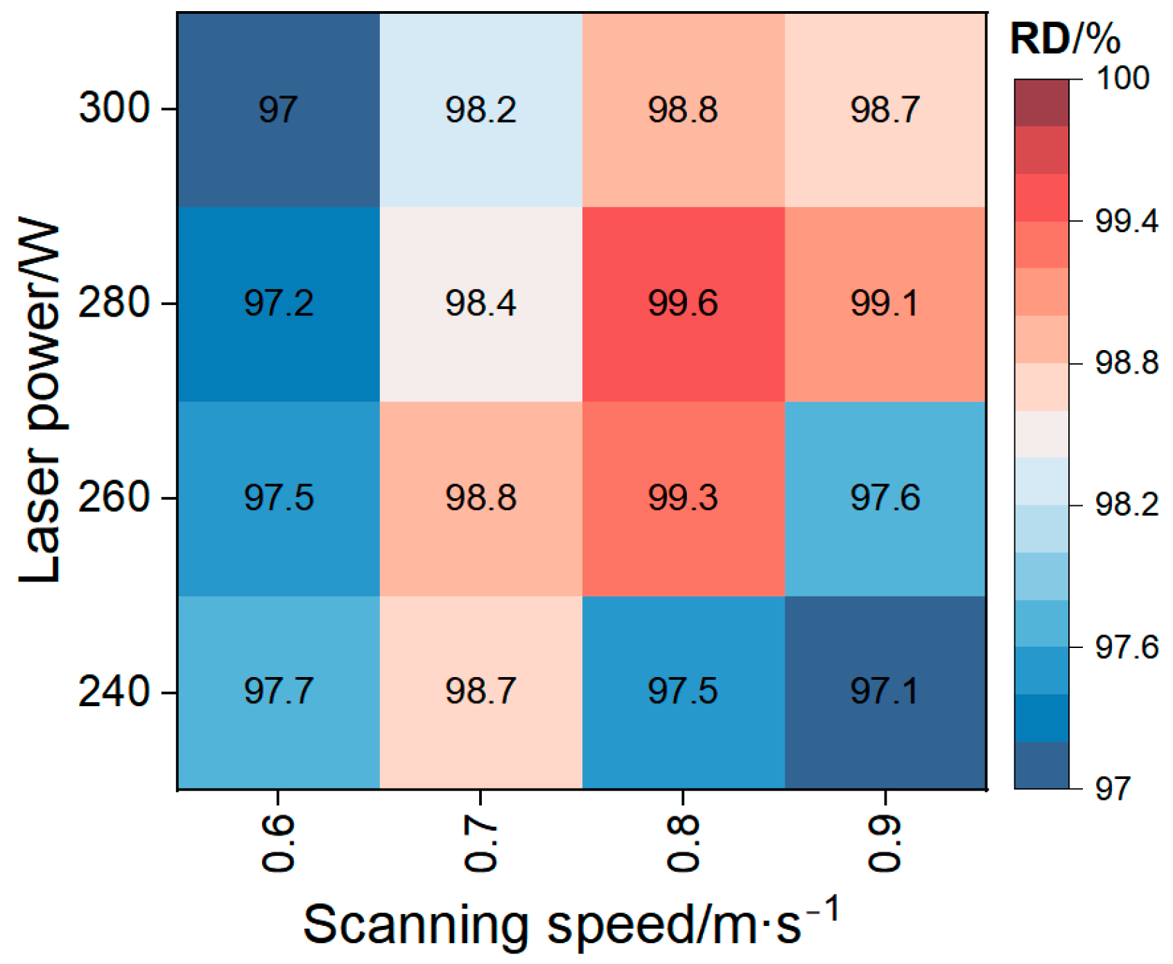
The quality of an AM part can be preliminarily evaluated by assessing its densification, as this directly influences its mechanical properties and overall performance [22,23]. A higher density typically correlates with improved performance. From a microstructural perspective, smaller internal voids and more closely packed grains reduce the likelihood of stress concentration and crack propagation, thereby enhancing the material’s strength and hardness. In contrast, low material density can lead to premature failure [24]. Figure 3 illustrates the effects of two key L-PBF process parameters (i.e., laser power and scanning speed) on the relative densities of the M2 HSS samples. As shown, with an increase in both laser power and scanning speed, the relative density initially increases before gently decreasing. Moreover, the relative density remains above 97% under all conditions, reaching 99.6% when the laser power and scanning speed are set to 280 W and 0.8 m s−1, respectively.
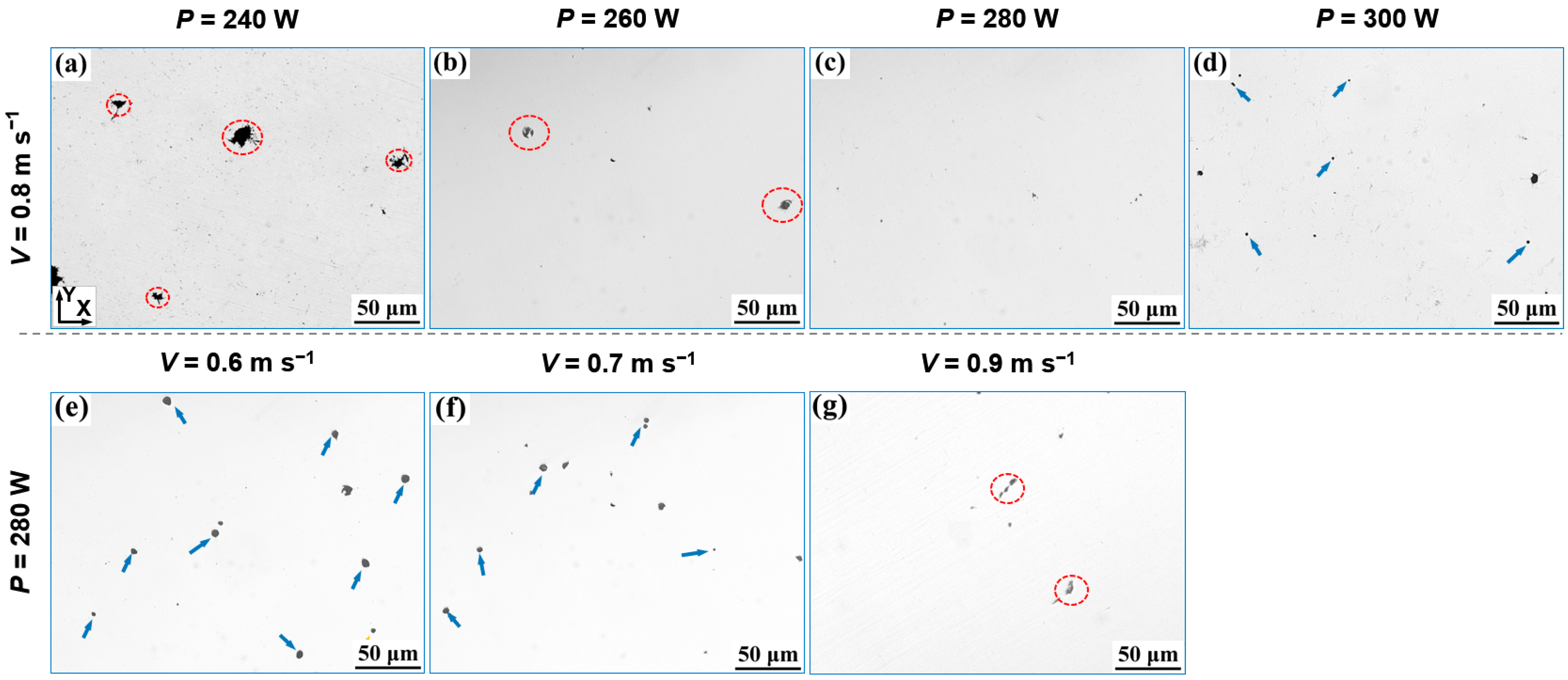
Figure 4 shows the representative OM images of the M2 HSS specimens produced under different process parameters. When a laser power of 240 W and a scanning speed of 0.8 m s−1 were used, unmelted pores (as marked by dashed ellipses) were clearly visible (Figure 4a), likely resulting from insufficient energy for powder melting. As the laser power increased (Figure 4b–d), the higher energy input significantly reduced the occurrence of unmelted defects. However, when the laser power was set to 300 W, smaller spherical gas pores with a size of <5 μm and keyhole defects were also observed (as denoted by solid arrows). Excessive energy input generally enhances the Marangoni effect, hindering the escape of protective gas surrounding the molten pool or gas adsorbed by the powder. This restriction leads to gas pore formation during rapid cooling and material shrinkage [25]. On the other hand, excessive energy can cause rapid material vaporization, increasing gasification recoil pressure and potentially resulting in severe spattering [16]. Similarly, when a laser power of 280 W and scanning speed of 0.6–0.7 m s−1 were applied (Figure 4e,f), significant spherical gas pores were also formed in the samples, with a larger size of approximately 10 μm. Notably, no microcrack formation was observed in any of the samples.
The above findings clearly demonstrate that appropriate adjustment of laser power and scanning speed during L-PBF can significantly enhance the melt quality of M2 HSS. Such optimization minimizes internal defects, enhances relative density, and ensures superior overall performance.

3.2. Microstructures

Given the rapid cooling and rapid solidification characteristics of L-PBF, the multi-channel, layer-by-layer metal fabrication process not only involves repeated melting and solidification cycles, but also subjects the material to the thermal influence of adjacent unmelted regions [26]. The dynamic evolution of the temperature field within the build area induces a series of thermal modifications at various locations within the molten pool, which in turn significantly affect the resulting material microstructure and properties of the material. In the experiments described in the subsequent subsections, the fully dense M2 HSS specimen fabricated at 280 W and 0.8 m s−1 is selected as a representative sample for analyzing microstructural characteristics across different regions along the build direction. For brevity, M2/0, M2/3, M2/6, and M2/9 are used to denote different regions along the build height, as shown in Figure 2b.

3.2.1. Phase Composition

Figure 5 shows the phase compositions of the M2/0, M2/3, M2/6, and M2/9 microstructures. It is evident that the microstructure, from the base to the top layer, is mainly composed of an α-Fe matrix, with the presence of γ-Fe (i.e., retained austenite) and precipitated M2C/M6C carbides. The strongest martensite diffraction peaks for {100} and {200} were observed within 2θ ranges of 43–46° and 63.6–65.4°, respectively. In contrast, the {200} austenite diffraction peak at 50–51° was relatively weak. It was reported that the primary reason for retained austenite formation in L-PBF-fabricated carbon-containing steel tools is the significant microsegregation of carbon between grains during rapid cooling. This carbon segregation plays a key role in stabilizing austenite [27]. Additionally, the high residual stress generated by the rapid cooling rates inherent to the L-PBF process can also promote the formation of retained austenite (i.e., mechanical stabilization of austenite [28]). Additionally, the relative contents of α-Fe and retained austenite phases change along the build direction. Specifically, the diffraction peak corresponding to the body-centered cubic structure gradually weakens, while the face-centered cubic structure continuously intensifies with the increasing build height. These observations indicate that the α-Fe content is higher near the substrate, whereas the top layer contains a greater amount of the retained austenite. During the L-PBF process, heat is primarily transferred from the top to the bottom towards the substrate. As a result, the cooling rate of the molten pool generally increases with the build height [29], resulting in higher residual stress in the top layer, thus retaining more austenite.

3.2.2. Grain Structure

To facilitate a comprehensive examination of the impact of complex thermal history on grain structure, the M2/0, M2/3, M2/6, and M2/9 specimens were characterized using EBSD. The inverse pole figure (IPF) plots, along with the corresponding distributions in the XY plane, are presented in Figure 6a–d. In each IPF plot, the grains are colored according to their orientation relative to the reference crystal orientation, as shown in the inset of Figure 6a. These results confirm that the L-PBF-fabricated M2 HSS predominantly consists of fine lath/needle-like and equiaxed grains. The microstructure exhibits clear variations across different build regions: near the bottom layer, the grains are mainly lath or needle-like shaped, while equiaxed characteristics become increasing prominent near the top layer. Moreover, all specimens exhibit a weak crystal texture. The grain size distributions are shown in Figure 6e–h, along with their corresponding mean values and standard deviations. As shown, the average grain sizes for the M2/0, M2/3, M2/6, and M2/9 specimens were found to be 1.15 ± 0.56,1.61 ± 0.96, 1.52 ± 0.85, and 1.45 ± 1.02 μm, respectively. In L-PBF-fabricated M2 HSS, the region closest to the substrate exhibits the smallest grain size, while the grain sizes in other regions are relatively uniform, with no significant variation. This localized grain refinement near the bottom is primarily attributed to the crystallographic mismatch between M2 HSS and the 304 L SS substrate. Such a mismatch limits epitaxial grain growth during the rapid solidification of the molten pool [30]. It should be noted that the grain sizes in this study were quantified using the equivalent circle diameter method. As a result, these values may systematically differ from the visual estimates based on the IPF map due to the geometric simplification inherent to this method. To further quantify the phase content changes observed through XRD, the phase distributions of the M2/0, M2/3, M2/6, and M2/9 microstructures were analyzed in detail using EBSD, as shown in Figure 6i–l. The α-Fe contents in the overall compositions of the M2/0, M2/3, M2/6, and M2/9 specimens were determined to be 96.5, 90.6, 81.2, and 68.4%, respectively, while the corresponding γ-Fe contents were 0.9, 6.5, 16.8, and 29.1%, respectively. The γ-Fe content in the top layer significantly increased by 28.2% as compared to the base area, further indicating that the top layer contained a greater quantity of retained austenite than the bottom layer. For comparative validation, the γ-Fe content was independently determined from XRD patterns and is presented in Table 2. The results closely match the quantitative analysis obtained from EBSD.

3.2.3. Precipitation

Figure 7 shows the SEM images of all the specimens after slightly etching, where needle-like structures oriented at specific angles to the matrix are visible across all samples (as marked by solid arrows). Additionally, as shown in Figure 7f, a magnified view of the region marked as point 1 for M2/9 (Figure 7e) reveals that these features primarily consist of fine ε-carbides enriched in C (atom fraction: 26.4%) and Fe (atom fraction: 59.2%). These needle-like structures are thus identified as characteristic of the lower bainite phase [31,32,33]. Generally, the presence of lower bainite in steel is beneficial for enhancing toughness and achieving an optimal balance between strength and toughness [34]. In conventional processes, the formation of lower bainite typically requires isothermal quenching, which involves austenitizing followed by quenching at a temperature above the martensite transformation start (Ms) temperature and then holding for a specified duration. In the case of L-PBF-fabricated M2 HSS, the formation of lower bainite is facilitated by substrate preheating to 260 °C. This preheating ensures that the termination temperature of the rapid cooling process remains above the Ms temperature of M2 HSS (which is <200 °C under nominal compositions). As a result, the cooling process promotes bainitic transformation rather than martensitic transformation [35]. Moreover, the results presented in Figure 7a–d indicate a significant decrease in the lower bainite phase content with increasing build height. More specifically, regions near the substrate exhibit a higher concentration of bainite compared to those near the surface. This variation can be attributed to the greater degree of thermal accumulation near the substrate, which retains the HSS within the lower bainite formation window for a longer duration. As a result, bainitic transformation in the lower regions is more complete.
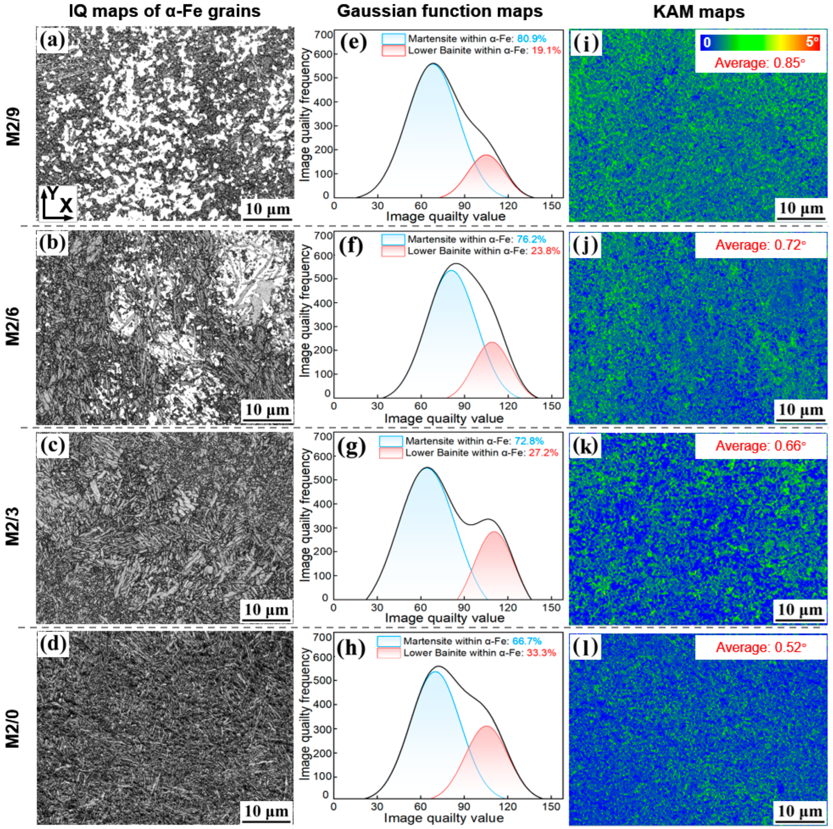
Based on the differences in lattice distortion and strain state between lower bainite and martensite, lower bainite typically exhibits higher-quality Kikuchi band patterns compared to martensite [36]. To evaluate the variations in lower bainite content along the build direction, a Gaussian fitting analysis was performed on image quality (IQ) maps of α-Fe grains (Figure 8a–h), with the corresponding results presented in Figure 8e–h. The IQ data were discretized into 30 intervals within the range of 20 to 170°. For the needle-like structures observed in the M2/0, M2/3, M2/6, and M2/9 specimens, the corresponding lower bainite proportions in the α-Fe phase are 33.3, 27.2, 23.8, and 19.1%, respectively, which are consistent with the SEM results. Further statistical analysis was conducted on the phase area fractions across all specimens, with the results summarized in Table 3. As the build height increases, the area fraction of lower bainite within the microstructure decreases significantly from 32.1 to 13.1%. In contrast, the martensite content remains relatively stable at approximately 60%, exhibiting no significant dependence on build height. Additionally, Kernel Average Misorientation (KAM) maps for all specimens are depicted in Figure 8i–l, calculated using a maximum misorientation angle of 5° and a kernel size of 3 × 3 pixels. It is evident that the KAM value, which serves as an indicator of local plastic strain and dislocation density, increases from 0.52 to 0.85° with build height. In addition, the residual stresses of M2/0 to M2/9 were quantified using the XRD-sin2ψ method, yielding values of 274, 367, 501 and 642 MPa, respectively. These results further indicate the presence of relatively high residual stress near the top layers of the build.
In general, the content and distribution of alloy carbides—particularly those involving elements like Cr, Mo, V, and W—play a vital role in determining the performance of HSS. However, microstructural characterization (Figure 6 and Figure 7) reveals that in M2 HSS prepared by L-PBF, no significant formation of alloy carbides was observed. At all build heights, the detected area fractions of such carbides remained consistently below 2.9% (Table 3). The low carbide content can be attributed to two main reasons: (i) the high-temperature melting during powder particle fusion may cause decomposition or dissolution of pre-existing alloy carbides and (ii) the extremely high cooling rate in the L-PBF process inhibits carbide precipitation from the molten pool [37,38]. To further investigate the carbide phase characteristics, TEM analysis was conducted, and the results are presented in Figure 9. The TEM images reveal two distinct carbide morphologies dispersed within the matrix: irregular carbides (~100 nm) and spherical carbides (~20 nm) (Figure 9a,b). The former are likely primary eutectic carbides formed along prior austenite grain boundaries during rapid solidification, while the latter are precipitated ε-carbides within the ferrite phase (Figure 9c). Additionally, selected area electron diffraction (SAED) confirmed that the primary carbide type is M6C (Figure 9d).
Figure 10 illustrates a schematic diagram of the microstructural evolution of L-PBF-fabricated M2 HSS along the build height. As indicated, the formation and distribution of martensite, lower bainite, retained austenite, and carbides are primarily governed by the cooling rate of the molten pool and the subsequent thermal history. Near the substrate, where the preheating temperature (260 °C) is slightly higher than the Ms temperature of M2 HSS, a portion of the austenite is transformed into needle-like lower bainite during cooling. Moreover, the microsegregation of carbon and the high residual stress generated by rapid cooling jointly stabilize the austenite phase, resulting in the retention of equiaxed austenite grains at prior austenite grain boundaries. Meanwhile, the high cooling rate of the L-PBF process significantly hinders carbide precipitation in the molten pool, leading to the formation of only a small volume fraction of nanoscale dispersed carbides throughout the matrix. This aligns with previous TEM observations of limited M6C and ε-carbide phases. Due to the incremental deposition strategy of the L-PBF process, each newly formed top layer (TL) remains above the Ms temperature for a shorter period as the build height increases. This results in reduced transformation time for austenite-to-lower bainite formation and, consequently, a decreasing trend in lower bainite content with increasing height. Conversely, during the L-PBF process, heat conduction primarily flows towards the substrate, meaning that the top layers cool faster and experience a greater thermal gradient. This promotes higher residual stresses in the upper regions. These stresses mechanically stabilize austenite, enhancing the retention of retained austenite in the top layers upon solidification. Additionally, the limited thermal exposure above the Ms temperature in these layers further restricts the formation of bainite, reinforcing the trend of a martensite + retained austenite-dominated microstructure near the top of the build.

3.3. Hardness and Tensile Properties

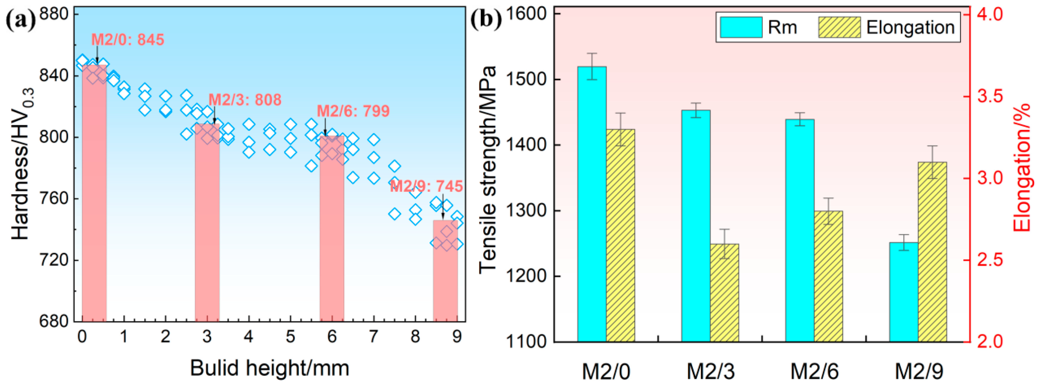
Figure 11a reveals the variation in hardness with build height for L-PBF-fabricated M2 HSS processed under 280 W and 0.8 m s−1. As the build height increases from 0 to 9 mm, the hardness gradually decreases from about 850 to 730 HV0.3. The average hardness values of the M2/0, M2/3, M2/6, and M2/9 specimens are also plotted in Figure 11a. Specifically, the hardness value in the M2/0 section (closest to the substrate) is 845 HV0.3, which is higher than those of the other regions. This is primarily attributed to its finer grain structure (~1.15 μm) and higher martensite/lower bainite content (96.5%). Finer grains increase the density of grain boundaries, thereby enhancing their ability to obstruct and trap dislocations during intragranular slipping. Consequently, a greater external force is required to activate dislocation motion between adjacent grains [39]. In addition, the high proportion of martensite and lower bainite content contribute to increased strength through solid-solution strengthening and a dense dislocation network, making this phase essential for improving overall material strength [40]. It is reported [41] that the hardness value of quenched and tempered wrought M2 HSS (microstructure: lath martensite and more than 15% carbides) is as high as about 870 HV0.3. The main reason for the slight deficiency in the hardness of the M2/0 specimen with a finer microstructure compared to its wrought bulk counterpart is its lower carbide content. Furthermore, the hardness values of the M2/3 and M2/6 specimens decreased to 808 and 799 HV0.3, respectively, which can be explained by their larger grain size (1.52–1.61 μm) and higher austenite content (6.5–16.8%). As expected, with a further significant increase in austenite content (29.1%), the hardness value of the M2/9 specimen decreased to 745 HV0.3, which was only 88.2% of the M2/0 specimen’s hardness.
Figure 11b illustrates the tensile strengths and elongations of the M2/0, M2/3, M2/6, and M2/9 specimens. Among all specimens, M2/0 shows the optimal performance, with a tensile strength of 1520 MPa and an elongation of 3.3%. Quenched and tempered wrought M2 HSS is known for its high strength (1600 MPa) but very low elongation (<1.5%) [42]. Similarly to hardness, the slightly lower tensile strength of the M2/0 specimen compared to its wrought bulk counterpart can be attributed to its lower carbide content. However, the presence of less bainite, finer microstructures, and reduced carbide content in the M2/0 specimen significantly improves plasticity while still maintaining relatively high strength. As the build height increases to 3 mm, both strength (1453 MPa) and plasticity (2.6%) decrease. This decline in strength is primarily due to increased austenite content and grain coarsening. The decrease in plasticity, despite higher austenite content, may be due to the adverse effects of higher residual stress levels (Figure 8k). With further increases in build height, the strength of the M2/6 and M2/9 specimens continues to decrease (1439 and 1251 MPa), but their plasticity improves slightly (2.8 and 3.1%). This suggests that the increase in austenite content has a stronger effect on enhancing plasticity than the adverse effects of residual stress. However, higher residual stress levels still result in slightly lower plasticity in the M2/9 specimen compared to the M2/0 specimen, even though the M2/9 specimen has higher austenite content.
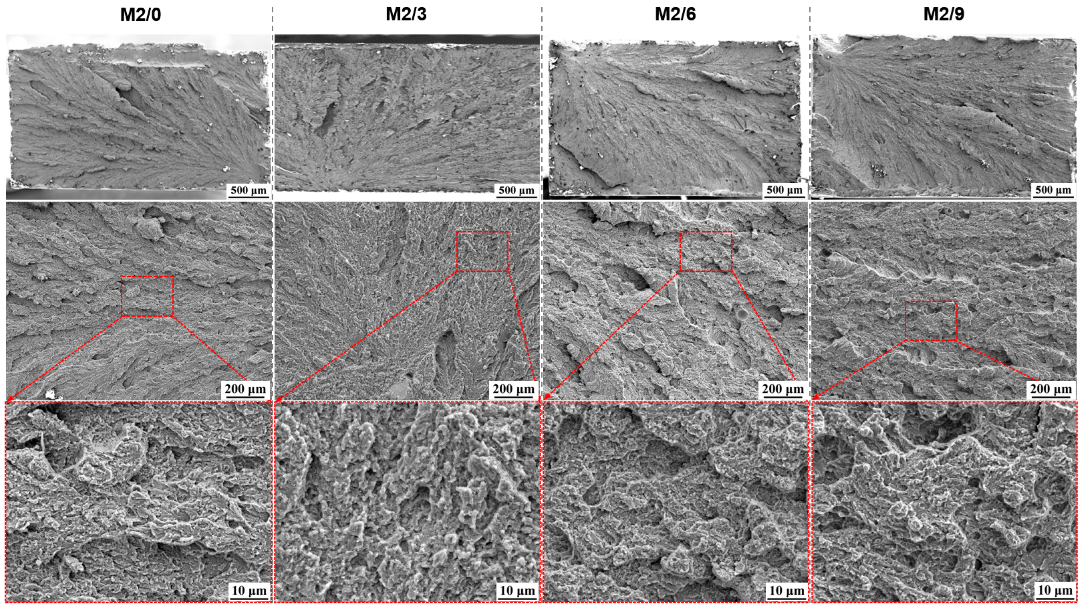
Figure 12 presents the fracture morphology of all the specimens after room-temperature tensile tests. The SEM images reveal that the predominant fracture mode is typical of a quasi-cleavage fracture, which exhibits characteristics of both cleavage and ductile fracture. At the macroscopic scale, the fracture surfaces show a distinct river-like pattern, which is characteristic of brittle fracture. This indicates that crack propagations occur via cleavage fracture along specific crystallographic planes. When these propagating cracks encounter grain boundaries or other microstructural obstacles, stepped cleavage facets form as the cracks converge. At the microscopic scale, several notable characteristics are observed on the fracture surface. Firstly, isotropically distributed dimples are present, indicating that the material retains some capacity for local plastic deformation. Secondly, clear traces of microcrack propagation are visible at the edges of pore defects, indicating that these internal pore defects, which cannot be completely eliminated during the L-PBF process, serve as primary sites for crack initiation under tensile stress. In addition, the fracture surface exhibits numerous flat and bright cleavage steps, further confirming that, despite the improved plasticity compared to their wrought bulk counterparts, all specimens still display brittle fracture behavior. Notably, the fabricated samples also exhibit considerable residual stress and a clear interconnected network of microcracks. These features, combined with the presence of a high-hardness lath-martensitic phase, increase the likelihood of crack nucleation under mechanical loading [43]. In particular, at the interfaces between these hard, brittle phases and the surrounding matrix, mismatches in elastic moduli and thermal expansion coefficients exacerbate the stress concentration, thereby enhancing susceptibility to fracture and ultimately leading to the occurrence of quasi-cleavage fracture.
In short, L-PBF-fabricated M2 HSS exhibits notable performance variation along the build height due to its heterogeneous microstructure. In this study, the layer closest to the substrate exhibits superior hardness and tensile properties compared to the near-surface layer, highlighting the strong dependence of mechanical properties on build position. The non-uniformity poses a challenge in predicting the overall mechanical performance of L-PBF components and may lead to undesirable outcomes in critical applications. For components that cannot undergo high-temperature heat treatment, it becomes essential to explore in situ microstructure control strategies (such as interlayer thermal compensation or remelting) during the L-PBF process. Such approaches can help achieve consistent and enhanced mechanical properties throughout the entire component.

4. Conclusions

In this study, high-density M2 high-speed steel (HSS) was fabricated via a laser powder bed fusion (L-PBF) process. The relationship between microstructural features and mechanical performance (hardness and tensile properties) was analyzed across different build heights, taking into account the varying thermal history of each layer during the L-PBF process. Conclusions can be drawn based on the obtained results:
(1)
By optimizing the laser power (280 W) and scanning speed (0.8 m s−1), high-density M2 HSS with a relative density of 99.6% was successfully produced.
(2)
The microstructure of M2 HSS is primarily composed of lath martensite, needle-like lower bainite, and retained austenite, accompanied by a minor fraction (less than 2.9%) of eutectic M6C and M2C carbides. As the build height increases (0 to 9 mm), significant variations in phase composition are observed, along with a corresponding increase in residual stress. Specifically, the area fraction of lower bainite decreases significantly, from 32.1 to 13.1%, while the retained austenite content increases from 0.9 to 29.1%. Meanwhile, the average grain size remains between 1.15 and 1.61 μm.
(3)
The heterogeneous distribution of microstructures along the build direction plays a critical role in determining the mechanical properties at different build heights. As the distance from the substrate to the surface increases, both hardness and tensile strength gradually decrease, from 845 HV0.3 and 1520 MPa to 745 HV0.3 and 1251 MPa, respectively. Meanwhile, the elongation value (2.6–3.3%) exhibits a trend of initial decrease and subsequent increase.
A detailed thermo-kinetic modeling of the L-PBF process will be a central focus of our future research, aimed at quantitatively elucidating the bainitic transformation in M2 HSS observed in this study.

Author Contributions

Investigation, Y.Z., S.Z. and X.Z.; data curation, Y.Z. and Y.L.; writing—original draft preparation, Y.W.; writing—review and editing, X.C.; supervision, S.L.; project administration, Y.L. and Y.R.; funding acquisition, Y.W. and S.L. All authors have read and agreed to the published version of the manuscript.

Funding

This work was supported by National Natural Science Foundation of China (52304357, 52434009), Young Elite Scientist Sponsorship Program by CAST (YESS20240807), and Shaanxi Outstanding Youth Science Foundation (2024JC-JCQN-52).

Data Availability Statement

The raw data supporting the conclusions of this article will be made available by the authors on request.

Conflicts of Interest

The authors declare no conflicts of interest.

References

  1. Xiang, J.; Yang, H.; Zhuang, C. Effect of cooling rate on the characteristics of eutectic carbides in M2Al high-speed steel. Crystals 2025, 15, 493. [Google Scholar] [CrossRef]
  2. Wei, Y.K.; Luo, T.; Zhang, W.; Wang, J. Electron beam melting powder bed forming M2 high speed steel corrosion resistance. J. Powder Metall. Technol. 2025, 4, 391–406. [Google Scholar] [CrossRef]
  3. Liu, S.; Sun, Z.; Wei, Y.; Wang, Y.; Wang, J.; Zhang, L.; Yang, X.; Tang, H. Research progress on powder bed fusion additive manufacturing of tool and mold steels. Iron Steel 2024, 59, 2–21. [Google Scholar] [CrossRef]
  4. Halfa, H. Characterization of electroslag remelted super hard high speed tool steel containing niobium. Steel Res. Int. 2013, 84, 495–510. [Google Scholar] [CrossRef]
  5. Peng, H.; Hu, L.; Li, L.; Zhang, L.; Zhang, X. Evolution of the microstructure and mechanical properties of powder metallurgical high-speed steel S390 after heat treatment. J. Alloys Compd. 2018, 740, 766–773. [Google Scholar] [CrossRef]
  6. Narasimharaju, S.; Zeng, W.; See, T.; Zhu, Z.; Scott, P.; Jiang, X.; Lou, S. A comprehensive review on laser powder bed fusion of steels: Processing, microstructure, defects and control methods, mechanical properties, current challenges and future trends. J. Manuf. Process. 2022, 75, 375–414. [Google Scholar] [CrossRef]
  7. Yin, F.; Wang, L.; Xiao, Z.; Feng, J.; Zhao, L. Effect of titanium and rare earth microalloying on microsegregation, eutectic carbides of M2 high speed steel during ESR process. J. Rare Earths 2020, 38, 1030–1038. [Google Scholar] [CrossRef]
  8. Iqbal, A.; Zhao, G.; Suhaimi, H.; Ning, H.; Ghulam, H.; Wei, Z. Readiness of subtractive and additive manufacturing and their sustainable amalgamation from the perspective of Industry 4.0: A comprehensive review. Int. J. Adv. Manuf. Technol. 2020, 111, 2475–2498. [Google Scholar] [CrossRef]
  9. Marrey, M.; Malekipour, E.; El-Mounayri, H.; Faierson, E.; Agarwal, M. A novel framework of developing a predictive model for powder bed fusion process. 3D Print. Addit. Manuf. 2024, 11, 179–196. [Google Scholar] [CrossRef]
  10. Schweizer, F.; Bade, K.; Baldas, L.; Bergdolt, S.; Colin, S.; Deutschbein, C.; Hengsbach, S.; Korvink, J.; Rojas-Cárdenas, M.; Brandner, J. Rarefied gas flows in complex microfluidic 3D-structures fabricated via additive manufacturing. Vacuum 2025, 238, 114213. [Google Scholar] [CrossRef]
  11. Liu, Z.; Zhou, Q.; Liang, X.; Wang, X.; Li, G.; Vanmeense, K.; Xie, J. Alloy design for laser powder bed fusion additive manufacturing: A critical review. Int. J. Extrem. Manuf. 2024, 6, 022002. [Google Scholar] [CrossRef]
  12. Wang, Y.; Luo, L.; Liu, T.; Wang, B.; Luo, L.; Zhao, J.; Wang, L.; Su, Y.; Guo, J.; Fu, H. Tuning process parameters to optimize microstructure and mechanical properties of novel maraging steel fabricated by selective laser melting. Mater. Sci. Eng. A 2021, 823, 141740. [Google Scholar] [CrossRef]
  13. Yadroitsev, I.; Krakhmalev, P.; Yadroitsava, I.; Johansson, S.; Smurov, I. Energy input effect on morphology and microstructure of selective laser melting single track from metallic powder. J. Mater. Process. Technol. 2013, 213, 606–613. [Google Scholar] [CrossRef]
  14. Rahman, N.; Capuano, L.; Cabeza, S.; Feinaeugle, M.; García-Junceda, A.; Rooij, M.; Matthews, D.; Gibson, I.; Römer, G. Directed energy deposition and characterization of high-carbon high speed steels. Addit. Manuf. 2019, 30, 100838. [Google Scholar] [CrossRef]
  15. Haghdadi, N.; Laleh, M.; Moyle, M.; Primig, S. Additive manufacturing of steels: A review of achievements and challenges. J. Mater. Sci. 2021, 56, 64–107. [Google Scholar] [CrossRef]
  16. Bajaj, P.; Hariharan, A.; Kini, A.; Kürnsteiner, P.; Raabe, D.; Jägle, E. Steels in additive manufacturing: A review of their microstructure and properties. Mater. Sci. Eng. A 2020, 772, 138633. [Google Scholar] [CrossRef]
  17. Careri, F.; Khan, R.H.U.; Alshammari, T.; Attallah, M. Development of a novel heat treatment in L-PBF fabricated high strength A205 Al alloy: Impact on microstructure-mechanical properties. Mater. Sci. Eng. A 2025, 933, 148278. [Google Scholar] [CrossRef]
  18. Zhang, L.; Zheng, L.; Xu, W.; Liu, N.; Zhang, Y.; Liang, J.; Li, Z.; Zhang, G. Synergistic impact mechanism of particle size and morphology in superalloy powders for additive manufacturing. Particuology 2024, 95, 279–302. [Google Scholar] [CrossRef]
  19. ISO 2738:1999; Sintered Metal Materials, Excluding Hardmetals—Permeable Sintered Metal Materials—Determination of Density, Oil Content and Open Porosity. International Organization for Standardization: Geneva, Switzerland, 1999. Available online: https://www.antpedia.com/standard/404749.html (accessed on 23 May 2024).
  20. Jiao, W.; Li, H.; Feng, H.; Jiang, Z.; Dai, J.; Zhu, H.; Zhang, S.; Chu, M.; Wu, W. Effect of high nitrogen addition on microstructure and mechanical properties of as-cast M42 high speed steel. ISIJ Int. 2020, 60, 564–572. [Google Scholar] [CrossRef]
  21. ISO 6892-1:2016; Metallic Materials—Tensile Testing—Part 1: Method of Test at Room Temperature. International Organization for Standardization: Geneva, Switzerland, 2016. Available online: https://www.antpedia.com/standard/7803213.html (accessed on 23 May 2024).
  22. Liu, S.; Yang, W.; Shi, X.; Li, B.; Duan, S.; Guo, H.; Guo, J. Influence of laser process parameters on the densification, microstructure, and mechanical properties of a selective laser melted AZ61 magnesium alloy. J. Alloys Compd. 2019, 808, 151160. [Google Scholar] [CrossRef]
  23. Al-Maharma, A.; Patil, S.; Markert, B. Effects of porosity on the mechanical properties of additively manufactured components: A critical review. Mater. Res. Express 2020, 7, 122001. [Google Scholar] [CrossRef]
  24. Nabavi, S.; Dalir, H.; Farshidianfar, A. A comprehensive review of recent advances in laser powder bed fusion characteristics modeling: Metallurgical and defects. Int. J. Adv. Manuf. Technol. 2024, 132, 2233–2269. [Google Scholar] [CrossRef]
  25. Wang, T.; Chen, J.; Kang, X.; Zou, J.; Zou, Y.; Shi, W. Coupling effect of substrate thermal properties and droplet geometry on Marangoni instabilities inside an evaporating droplet at quasi-steady state. Int. Commun. Heat Mass Transf. 2025, 163, 108745. [Google Scholar] [CrossRef]
  26. Liu, Y.; Liu, Z.; Jiang, Y.; Wang, G.; Yang, Y.; Zhang, L. Gradient in microstructure and mechanical property of selective laser melted AlSi10Mg. J. Alloys Compd. 2018, 735, 1414–1421. [Google Scholar] [CrossRef]
  27. Han, L.; Wang, Y.; Liu, S.; Zhang, Z.; Song, X.; Li, Y.; Liu, W.; Yang, Z.; Mu, M. Effect of cryogenic treatment on the microstructure and mechanical properties of selected laser melted H13 steel. J. Mater. Res. Technol. 2022, 21, 5056–5065. [Google Scholar] [CrossRef]
  28. Lee, J.; Choe, J.; Park, J.; Yu, J.; Kim, S.; Jung, I.; Sung, H. Microstructural effects on the tensile and fracture behavior of selective laser melted H13 tool steel under varying conditions. Mater. Charact. 2019, 155, 109817. [Google Scholar] [CrossRef]
  29. Wei, Y.; Qi, S.; Wang, Y.; Chu, X.; Sun, Z.; Wang, J.; Zhang, L.; Jia, W.; Yang, X.; Liu, S. Microstructural evolution and tribological properties of M2 high-speed steel fabricated under various selective electron beam melting processing parameters. Tribol. Int. 2023, 187, 108749. [Google Scholar] [CrossRef]
  30. Huang, B.; Liu, Y.; Zhou, Z.; Cheng, W.; Liu, X. Selective laser melting of 7075 aluminum alloy inoculated by Al-Ti-B: Grain refinement and superior mechanical properties. Vacuum 2022, 200, 111030. [Google Scholar] [CrossRef]
  31. Kang, K.; Yuan, L.; Phillion, A. A 3D simulation of grain structure evolution during powder bed fusion additive manufacturing and subsequent laser rescanning process. J. Mater. Process. Technol. 2024, 333, 118603. [Google Scholar] [CrossRef]
  32. Hou, R.; Guevara, J.; Inoue, J. In-situ observation of variant pair formation in bainite of low carbon steel by digital holographic microscopy. Acta Mater. 2024, 277, 120212. [Google Scholar] [CrossRef]
  33. Shin, S.; Lee, S.; Hwang, B. In-situ SEM/EBSD investigation of tensile deformation-driven microstructural changes in low-carbon HSLA steels with ferrite-bainite microstructures. Mater. Charact. 2023, 206, 113418. [Google Scholar] [CrossRef]
  34. Castro, P.; Silveira, A.; Rocha, A.; Stark, A.; Sourmail, T.; Epp, J. Impact of hot and warm deformation on the bainite morphology and kinetics during continuous cooling of low- and medium-C carbide-free bainitic steels. Mater. Des. 2025, 257, 114433. [Google Scholar] [CrossRef]
  35. Foster, D.; Paladugu, M.; Hughes, J.; Kapousidou, M.; Islam, U.; Stark, A.; Schell, N.; Jimenez-Melero, E. Formation of lower bainite in a high carbon steel—An in-situ synchrotron XRD study. J. Mater. Res. Technol. 2022, 18, 5380–5393. [Google Scholar] [CrossRef]
  36. Kim, J.; Kim, J.H.; Park, J.; Baek, S.; Ma, N.; Lee, S.; Kim, D. Continuous tempering effect induced PWHT alternative technology using wire arc additivemanufacturing for application in replacing nuclear pressurized water reactor system repairing: CALPHAD, FEM simulation, and EBSD investigation. J. Mater. Res. Technol. 2023, 25, 1961–2988. [Google Scholar] [CrossRef]
  37. Yang, Y.; Zhao, X. Effect of scaning speed on microstructure and hardness of M2 high speed steel by direct laser metal deposition. Hot Work. Technol. 2019, 48, 73–76. [Google Scholar] [CrossRef]
  38. Okada, K.; Shibata, A.; Kimura, Y.; Yamaguchi, M.; Ebihara, K.; Tsuji, N. Effect of carbon segregation at prior austenite grain boundary on hydrogen-related crack propagation behavior in 3Mn-0.2C martensitic steels. Acta Mater. 2024, 280, 120288. [Google Scholar] [CrossRef]
  39. Cui, Q.; Jiang, S.; Lin, X.; Guo, Y.; Zhang, H.; Wen, B. High-pressure quenching effect on martensitic transformation characteristics and mechanical properties of low-alloy medium-carbon steel. J. Mater. Res. Technol. 2023, 23, 765–777. [Google Scholar] [CrossRef]
  40. Mouni, C.T.; Mahadevan, S.; Ravishankar, C.; Albert, S.K.; Das, C.R.; Parida, P.K.; Sagdeo, A. Influence of prior deformation temperature on strain induced martensite formation and its effect on the tensile strengthening behaviour of type 304 SS studied by XRDLPA. Mater. Sci. Eng. A 2021, 826, 141960. [Google Scholar] [CrossRef]
  41. Chaus, A.; Kryshtal, A. New insights into the microstructure of M2 high-speed steel. Mater. Charact. 2023, 205, 113313. [Google Scholar] [CrossRef]
  42. LI, Y.; Wang, Y.; Niu, J.; Liu, S.; Lin, Y.; Liu, N.; Ma, J.; Zhang, Z.; Wang, J. Microstructure and mechanical properties of M2 high speed steel produced by electron beam melting. Mater. Sci. Eng. A 2023, 862, 144327. [Google Scholar] [CrossRef]
  43. Wang, K.; Zhang, C.; Qu, F.; Liu, L.; Liu, X. Fe-based metallic glass coatings with suppressed cracks and enhanced wear resistance prepared by extreme high-speed laser cladding. Intermetallics 2024, 175, 108517. [Google Scholar] [CrossRef]
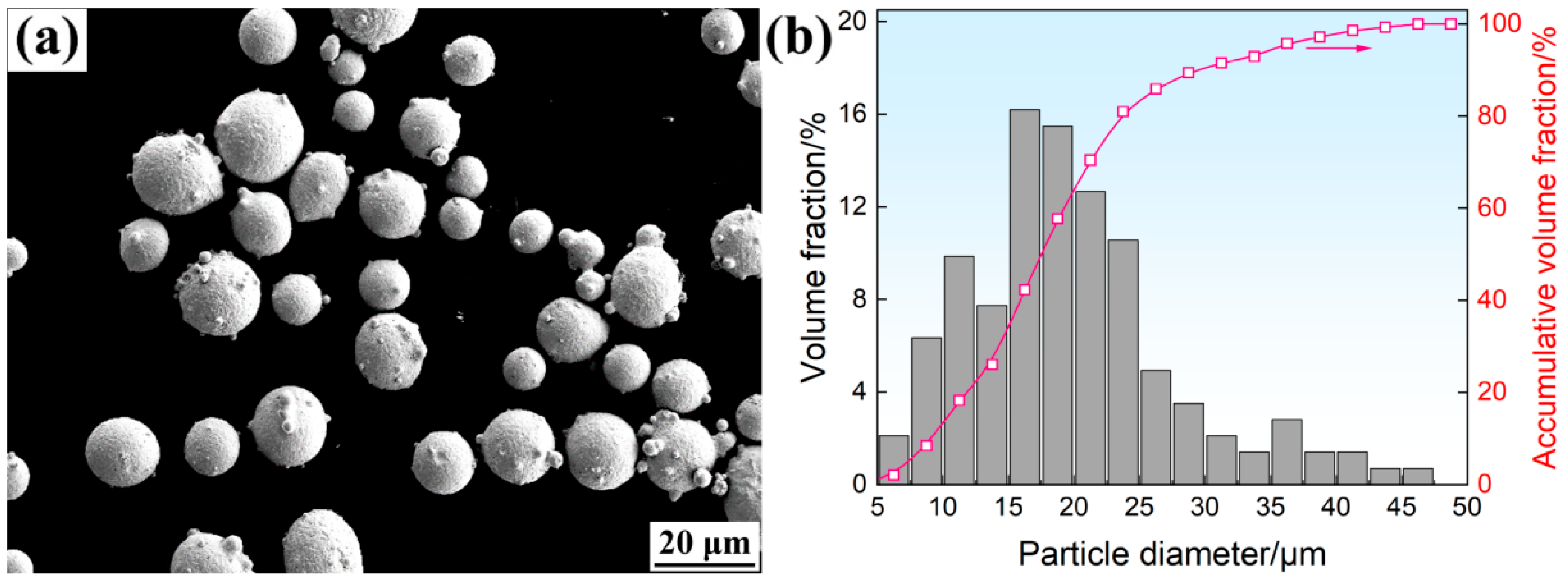
Figure 1. Surface morphology (a) and particle size distribution (b) of gas-atomized M2 HSS powder.
Crystals 15 00917 g001
Figure 2. L-PBF scanning strategy (a) as well as schematic diagrams of characterization areas and sampling locations (b).
Crystals 15 00917 g002
Figure 3. Relative density measurement results for the M2 HSS fabricated under various L-PBF laser powers and scanning speeds.
Crystals 15 00917 g003
Figure 4. OM images of the L-PBF-fabricated M2 HSS prepared under various process parameters; (a) 240 W and 0.8 m s−1; (b) 260 W and 0.8 m s−1; (c) 280 W and 0.8 m s−1; (d) 300 W and 0.8 m s−1; (e) 280 W and 0.6 m s−1; (f) 280 W and 0.7 m s−1; (g) 280 W and 0.9 m s−1.
Crystals 15 00917 g004
Figure 5. XRD patterns of L-PBF-fabricated M2 HSS specimens under various build heights.
Crystals 15 00917 g005
Figure 6. IPF maps (ad), grain size distributions (eh), and phase distribution maps (il) of the L-PBF-fabricated M2 HSS specimens under various build heights. d50 in (eh) represents the grain size corresponding to the 50% cumulative percentile.
Crystals 15 00917 g006
Figure 7. SEM images of L-PBF-fabricated M2 HSS specimens under various build heights: M2/0 (a); M2/3 (b); M2/6 (c); and M2/9 (d). (e) is a magnified view of the marked area indicated in (d). (f) shows the elemental analysis results of the carbide denoted by point 1 in (e).
Crystals 15 00917 g007
Figure 8. IQ maps of α-Fe grains (ad), Gaussian function maps (eh), and KAM maps (il) recorded for the L-PBF-fabricated M2 HSS specimens under various build heights.
Crystals 15 00917 g008
Figure 9. TEM bright-field (a) and dark-field (b) images of the L-PBF-fabricated M2 HSS; (c) and (d) are the SAED results for regions A and B in (b), respectively.
Crystals 15 00917 g009
Figure 10. Schematic diagram of microstructural evolution in the L-PBF-fabricated M2 HSS along build height.
Crystals 15 00917 g010
Figure 11. Hardness (a) and tensile properties (b) of the L-PBF-fabricated M2 HSS specimens under various build heights.
Crystals 15 00917 g011
Figure 12. Fracture morphologies of the M2/0, M2/3, M2/6, and M2/9 specimens.
Crystals 15 00917 g012
Table 1. Chemical composition of gas-atomized M2 HSS powder (wt.%).
CCrMoWVMnSiFe
0.84.15.16.51.90.30.2Bal.
Table 2. Calculated γ-Fe content in M2/0-M2/9 specimens based on XRD patterns.
SpecimensM2/0M2/3M2/6M2/9
γ-Fe content1.3%5.3%19.4%25.6%
Table 3. Statistical results of phase area fraction in all specimens based on EBSD data.
SpecimensMartensiteLower BainiteAusteniteM6C, M2C Carbides
Overall (within α-Fe)Overall (within α-Fe)
M2/064.4% (66.7%)32.1% (33.3%)0.9%2.6%
M2/366.0% (72.8%)24.6% (27.2%)6.5%2.9%
M2/661.9% (76.2%)19.3% (23.8%)16.8%2%
M2/955.3% (80.9%)13.1% (19.1%)29.1%2.5%
Disclaimer/Publisher’s Note: The statements, opinions and data contained in all publications are solely those of the individual author(s) and contributor(s) and not of MDPI and/or the editor(s). MDPI and/or the editor(s) disclaim responsibility for any injury to people or property resulting from any ideas, methods, instructions or products referred to in the content.