Article

Enhancement in the Capillary Performance of Aluminum Groove through Laser Textured Deposition

Laser Group, School of Mechanical Engineering, Hubei University of Technology, Wuhan 430068, China
*
Author to whom correspondence should be addressed.
Crystals 2023, 13(9), 1397; https://doi.org/10.3390/cryst13091397
Submission received: 27 August 2023 / Revised: 16 September 2023 / Accepted: 18 September 2023 / Published: 20 September 2023
(This article belongs to the Special Issue Additive Manufacturing of Alloys via Laser-Based Techniques)

Abstract

:
Groove is widely used in the wicks of heat pipes. In this paper, a laser texture deposition (LTD) process was proposed to texture deposit SiO2 in rectangular aluminum groove. Both the SEM and XPS analysis revealed that a fluffy SiO2 layer was deposited on the surface of alumina fluff, which increased the fluff density. Statistically, the density of fluff on the surface of LTD was 1.12 times higher than that on the laser texture (LT) surface, leading to an increase in porosity and decrease in effective capillary radius. This significantly improved the capillary performance of the LTD groove. The results showed that, compared to the Raw and LTD grooves, the increase in height of the LTD groove was enhanced by 2.42 and 1.07 times, respectively, in 5 s, while the capillary performance factor (M) was increased by 2.83 and 1.04 times, respectively, in 1 s. This study introduces a novel process for enhancing the capillary performance of aluminum groove.

1. Introduction

The phenomenon of capillary rise in grooves has been widely utilized in various fields including heat exchangers [1], microfluidic devices [2,3], water harvesting [4,5], and fuel cells [6,7]. During the capillary rise of a liquid, the capillary pressure generated by the surface tension of the liquid is the only driving force, whereas the viscous and gravitational forces are the main resistive forces [8]. The capillary performance of a wick is typically characterized by the average velocity of the linear phase and the height of the rise within a given time. With the development of microelectronics technology, all kinds of electronic devices are evolving in terms of various features such as integration, being lightweight, and having high performance [9]. High heat flow density leads to increased temperature and performance degradation of electronic devices, which seriously affects their reliability and service-life [10]. Due to this reason, efficient heat management is the key to ensuring the normal operation of electronic devices [11]. Heat pipes are efficient and reliable two-phase heat exchange devices, and widely used in heat management of electronic products for having efficient thermal conductivity and heat dissipation capability [12]. The wick, as the core component of the heat pipe [13], has capillary performance that determines the heat transfer capability of the heat pipe.
A single type of wick can no longer meet the heat dissipation needs of heat pipes, whereas composite wicks are an effective way to improve the performance of capillaries. Many researchers have proposed a variety of composite wicks to enhance capillary performance. Chen et al. [14] proposed a multilayer composite mesh microporous wick, and enhanced the capillary properties based on a combination of coarse and fine meshes with different numbers of layers. Dai et al. [15] bonded copper mesh with microchannels to make a mesh-groove microfilm composite wick, which effectively increased the capillary pressure and reduced the flow resistance. Duan et al. [9] prepared a dual-scale composite micro-slot wick through a combination of cross-plow cutting and surface chemical etching. It was found that the surface of corrosion grooves had a rich pore structure with significantly improved capillary performance. Deng et al. [16] developed a composite wick that integrated permeability and capillary pressure by coating sintered copper powder on a v-groove. The results showed that its capillary performance was significantly greater than that of single groove and powder particle wicks. Zhong et al. [17] prepared porous microstructures on the surface of aluminum groove using an ultrasonic modification method, and the maximum rise height and capillary performance parameters of the modified groove improved by a factor of three and one order of magnitude, respectively. Niu et al. [18] mixed copper powder with fibers and made a copper powder–fiber composite wick through sintering. The structure provided both high capillarity and good permeability. Huang et al. [19] treated axially-grooved aluminum wicks with alkaline corrosion, and reported that the micro-coarse-structured morphology and improved hydrophilicity of the corroded Al surface appeared to be the primary mechanisms responsible for the improvement. Xie et al. [20] analyzed the effect of wick structures on the heat transfer of vapor chamber and determined that a higher capillary pressure resulted in a greater driving force, while a higher permeability reduced the flow resistance. When capillary pressure and permeability were in equilibrium, excellent capillary performance was achieved.
With the evolution of green and clean processes, the laser is widely used for processing material surfaces because of its green nature, fast flexibility, and high precision. Li et al. [21] used a laser to prepare a novel groove on carbon nanofoam with good capillary performance, which was achieved by the combination of capillary pressure of the grooves and the permeability of the carbon nanofoam. Liu et al. [22] used laser etching of a copper mesh to produce a superhydrophilic microstructure on the surface of mesh to enhance the capillary performance. The effect of different etching areas on the heat transfer performance was investigated. Long et al. [23] used a nanosecond laser to texture a wick on a copper substrate, realizing a combination of a dual-scale porous structure and deep v-shaped groove, which exhibited good capillary performance. Other researchers [24,25] used a two-step laser processing method to prepare dual-scale and multi-scale microgroove wicks to obtain good capillary performance.
In the present work, SiO2 was deposited in a rectangular groove using the LTD process. The SiO2 layer covered the Al2O3 surface, which increased the density of fluff on the groove surface. The utilization of dense fluff could increase the porosity and decrease the effective capillary radius, which increased the capillary pressure of the groove and led to a significant improvement in the capillary performance. The increased density of fluff is the main reason for the enhanced capillary performance. In this study, a new LTD process is proposed to improve the capillary performance of aluminum grooves, and the mechanism of performance enhancement is also revealed. The LTD process can be used to enhance the capillary performance of suction wicks for flat heat pipes.

2. Experimental Section

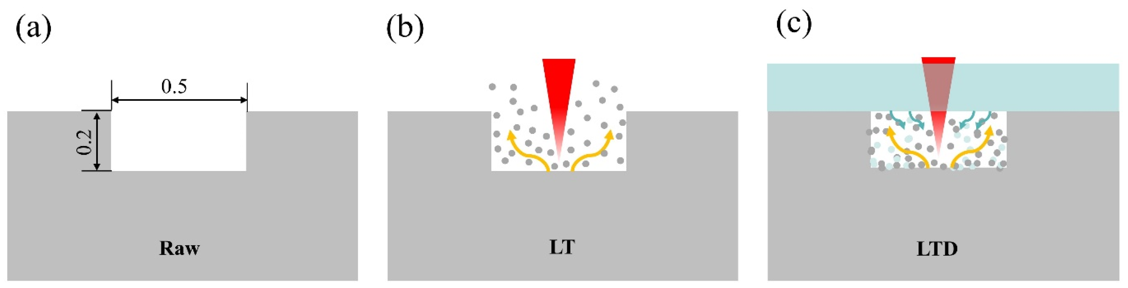
2.1. Sample Preparation and Laser Processing

The material used in this experiment was 6061 aluminum alloy (size 100 mm × 30 mm × 1 mm). Its main components included Al, Mg, and Si. The deposited material was a transparent substrate (Yancheng Yufan Experimental Equipment Co., Yancheng China) with SiO2 content of more than 90%. The aluminum plate and transparent substrate were sequentially cleaned in anhydrous ethanol (Analytically pure, Sinopharm Chemical Reagent Co., Shanghai China) and deionized water (Jiangsu Xizhimeng Trade Co., Zhangjiagang, China) using ultrasonic cleaner to remove surface impurities and oils. This would also help achieve a smooth result as laser would be able to act smoothly through the transparent substrate into the grooves. The samples of aluminum plates with clean surfaces and transparent substrates were blown-dry using cold air.
First, the groove was processed on the surface of aluminum plate using a miniature multifunctional desktop cutting machine (T60, Shenzhen Jingwu Technology Co., Ltd., Shenzhen China). Rectangular groove with the width of 0.3 ± 0.05 mm, depth of 0.2 ± 0.05 mm, and length of 100 mm was obtained. It was used as the “Raw” groove before laser treatment. The shape of the groove is shown in Figure 1a. After Raw groove was finished, high-pressure air was used to blow away any remaining debris to prevent it from melting and sticking to the surface of groove during laser processing. A nanosecond pulsed fiber laser (SP-100W-EP-Z, SPI Lasers Ltd., University of Southampton Optoelectronics Research Center UK) with spot diameter of 11 μm was used. The rectangular grooves were treated with LT and LTD processes at a scanning speed of 1400 mm/s and an energy density of 35.3 J/cm2 to prepare rectangular grooves with different surface structures. Table 1 lists the laser processing parameters. Both LT and LTD processes used the same scanning spacing to texture the micro-nanostructures in the same environment with orthogonal scanning in the XY-axis. A vacuum cleaner was used to adsorb and collect the dust generated during the processing to prevent contamination of the processing environment.
Figure 1b,c show the schematic of the laser treatment of the groove surface. As shown in Figure 1b, during the LT process, the high-energy pulsed laser beam acted directly on the inner surface of the groove, melting and evaporating aluminum under the action of laser. Meanwhile, a large number of particles were generated to diffuse directly into the air, and micro/nano structures with pores were processed on the surface of aluminum groove. As shown in Figure 1c, the LTD process involved a laser beam passing through a transparent substrate and applied to the inner surface of a rectangular groove. The transparent substrate was capped onto the rectangular groove and formed into a finite cavity. The laser action resulted in the generation of micro/nanostructures on the inner surface of the groove, as well as a large number of particles, which were confined to a limited space. The particles were impacted to the transparent substrate under the action of high-energy laser, which induced the substrate to undergo particle stripping. The two kinds of particles were fused at high temperatures and deposited onto the inner surface of the rectangular groove and the surface of the transparent substrate, resulting in the formation of a nanoscale fluffy composite layer of Al2O3 and SiO2 on the inner surface of the rectangular groove. Figure 2 shows the three-dimensional (3D) images of the three grooves. It can be seen that the groove shapes of Raw, LT, and LTD grooves were all rectangular. As shown in Figure 2a, the inner surface of the Raw groove exhibited flatness, whereas the groove geometry was regular. As shown in Figure 2b,c, the Raw groove was treated with LT and LTD. The inner surface of the grooves became rough and uneven, whereas complex morphology appeared after the treatment. The surface morphology was most complex due to the layer of SiO2 deposited on the surface of LTD groove. The surface roughness of Raw, LT, and LTD were measured using a confocal microscope, and were 1.13 μm, 7.24 μm, and 9.64 μm, respectively.
This research proposed a new LTD process that can improve the capillary performance of aluminum grooves, using SiO2 deposition layer to increase the fluff density on the groove surface to achieve the capillary performance enhancement. In the existing literature, the main processes for the preparation of grooved wicks are chemical corrosion and laser etching, and the LTD process is rarely used for capillary performance enhancement of wicks.

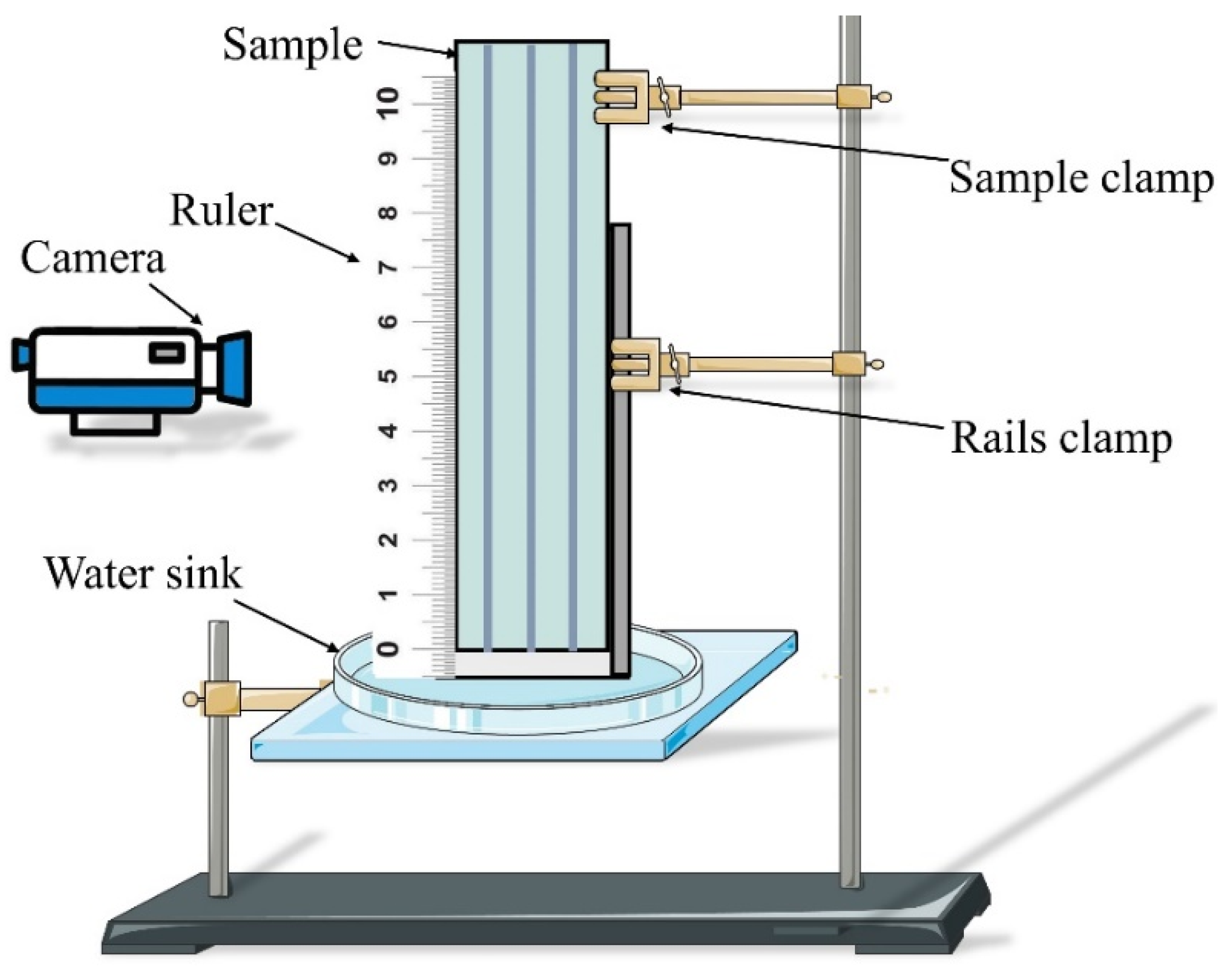
2.2. Measurement and Characterization

In order to understand the effect of different laser processes on the groove’s geometry and surface morphology, the shapes of three different grooves were observed using a confocal microscope (Zeiss LSM800, Carl Zeiss AG, Oberkochen Germany). Moreover, to understand the effect of different laser processes on the micro-morphology of the materials, a scanning electron microscope (SEM, SU8010, Hitachi Limited, Tokyo Japan) was used to observe the micro-morphology of the surfaces of three different samples. The SEM images were converted to grayscale images using ImageJ (1.8.0, National Institutes of Health, Bethesda, MD, USA) image processing software, and the area percentage of positive signals was calculated by adjusting the appropriate threshold size, resulting in the average optical density value of positive signals. The fluff density on the LT and LTD surfaces was characterized by the optical density value. Before testing, the specimens were dusted and dried to conform to the testing environment of the equipment. The surface wettability of different samples was measured by dropping 5 μL of deionized water on each sample using an optical contact angle meter (MAIST Vision A-300, Ningbo Haishu Maishi Testing Technology Ltd., Ningbo China). Each sample was measured three times and average values were used to minimize the measurement error. The surface chemical composition of different samples was analyzed using X-ray photoelectron spectroscopy (XPS, Thermos ESCALAB 250XI, Thermo Fisher Scientific, Waltham, MA, USA). Using Al as the excitation source of X-rays, the physical phase analysis was performed using an X-ray photoelectron spectrometer at a depth range of 10 nm on the surface of the sample at a beam diameter of 100 μm, a scanning range of 10–90°, a step size of 0.05°, speed of 1 (°)/s, and the resolution of 0.48 eV. Finally, electrical charge calibration was performed with C1s 284.8 eV. The capillary rise test was carried out on different grooves using a custom-made capillary rise test device.
Figure 3 shows the measurement setup for the capillary rise experiments. Deionized water was used as the working fluid in a room temperature environment. The test sample was placed on the skidway. When the sample was adjusted to 1 mm from the water surface, the sample clamp was released. The sample will instantly come into contact with water and be immersed in it for 3 mm. The advantage of this test method is that it can ensure that all three grooves are in contact with water at the same time, thus effectively avoiding contact errors caused by the surface tension of water. The water rose rapidly along the groove under capillary pressure, and the rise in water was recorded using the camera at a frame rate of 60 fps. After the test, the image data were post-processed using a computer to obtain capillary rise curves and analyze the capillary performance of different samples. When data extraction was performed, data were extracted every 0.25 s during the first 1 s, and every 0.5 s after 1 s. The experiment finished once it reached the 5th s.

3. Results and Discussion

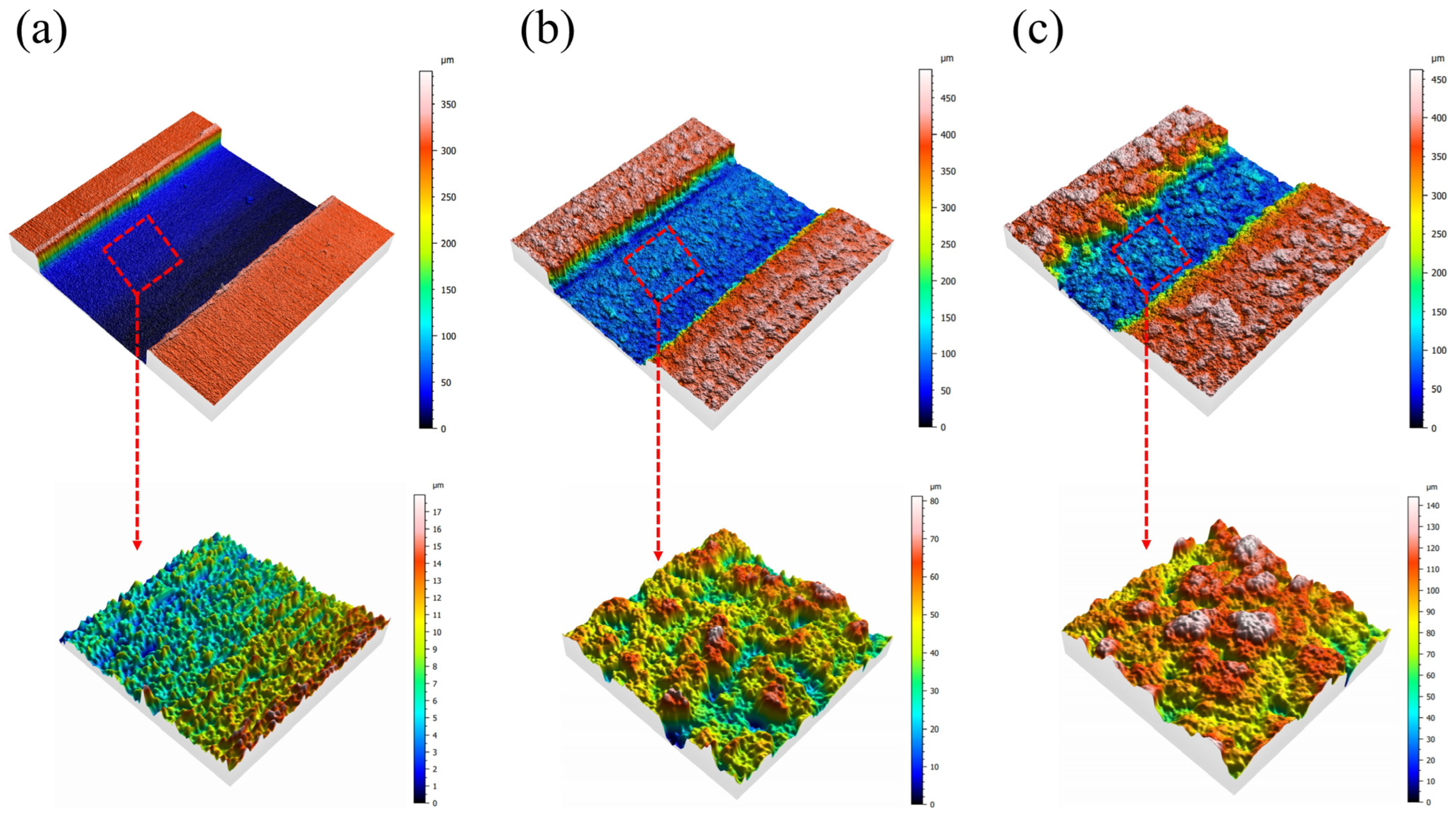
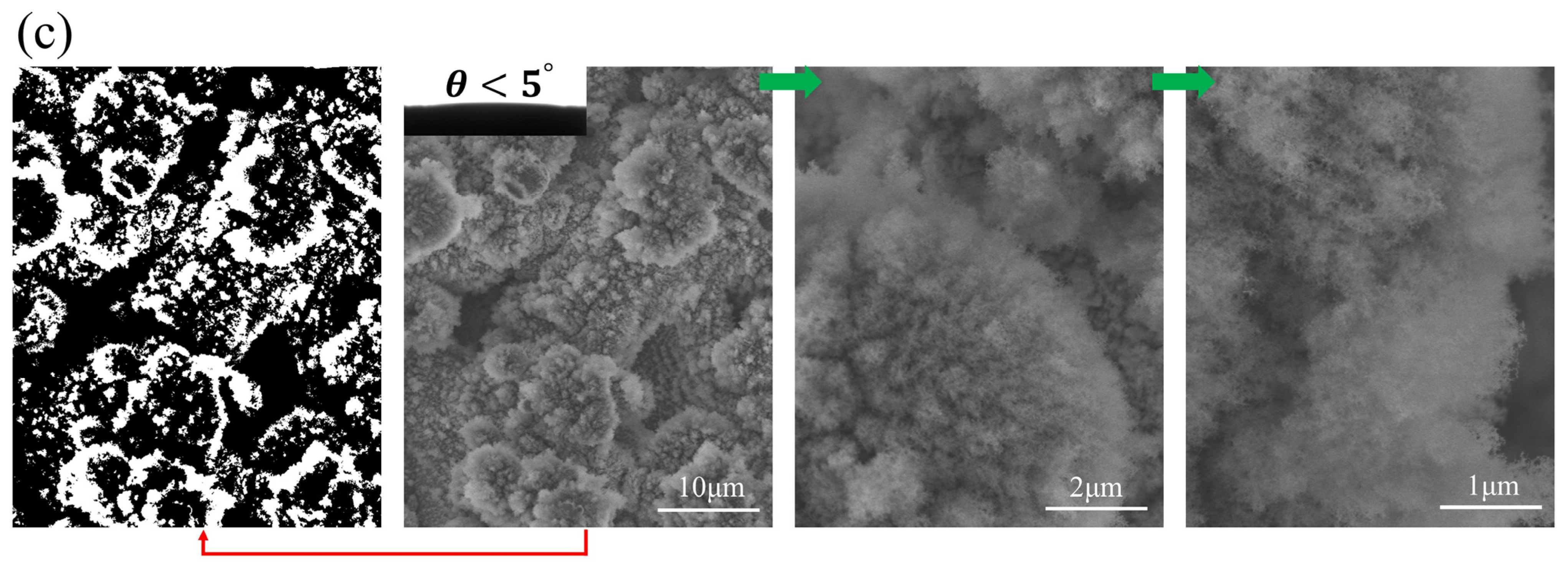
3.1. Surface Structure and Wettability

Figure 4 shows the grayscale and SEM images of Raw, LT, and LTD groove surfaces.
As shown in Figure 4a, the SEM image of the Raw groove surface shows that the groove surface was clean and flat, with only a few traces. No obvious microstructure was observed. The contact angle of the Raw surface was measured to be 72°, indicating hydrophilicity. As shown in Figure 4b, the surface of the LT groove was covered with a large number of papillae structures of micrometer size. The papillae adhered to each other to form a large number of irregular pores, which was conducive to the rapid infiltration of water. Under the magnification of 10,000× and 20,000×, it can be seen that the surface of papillae was covered with a layer of nanometer-sized villi, which provided secondary capillary pressure. The contact angle of the LT surface was measured to be less than 5°, which showed superhydrophilicity. Figure 4c shows the surface morphology of the LTD groove. It can be seen that the thickness and density of villi on the surface of the papillae increased significantly. The surface of the LTD groove exhibited a denser and more complex villous structure compared to the LT groove, which was due to the large number of villous SiO2 layers deposited on the nano-villi of alumina. The contact angle of the LTD surface was measured to be less than 5°, which showed superhydrophilicity.
The 2000× SEM image was converted to a grayscale image, in which the white part represented the micro/nano villous structure. The optical density values of the fluff on LT and LTD surfaces were calculated from the grayscale images to be 0.377 and 0.478, respectively, whereas the fluff density on the LTD surface was 1.27 times higher than that on the LT surface. Due to the increased density of micro/nano-fluffs on the LTD surface, it increased the porosity and decreased the effective capillary radius, thus enhancing the groove capillary pressure.

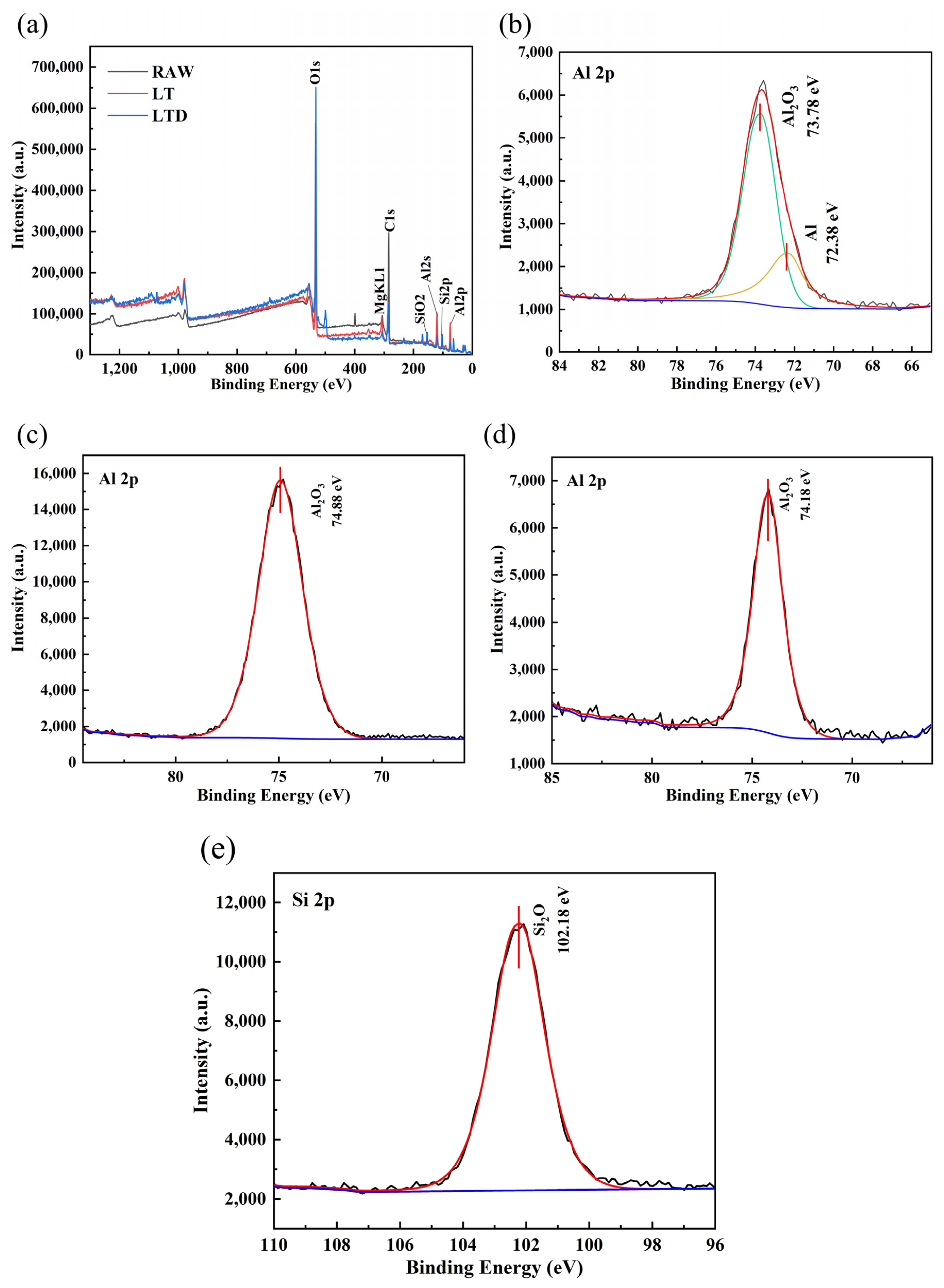
3.2. Surface Chemistry

The laser treatment caused a change in the surface wettability of the sample, which may be related to a change in the surface composition of the sample. In order to determine the surface chemical composition of different samples, XPS analysis was performed on the surface of three samples. Table 2 lists the elemental contents of the three sample surfaces determined using XPS. It can be seen that the oxygen contents of LT and LTD samples were significantly higher than that of the Raw sample, indicating that when the surface of the sample was treated with a laser, an oxidizing reaction occurred with air, resulting in the formation of an oxide layer with high surface energy. In addition, the elemental Si on the surface of LTD samples was significantly increased compared to Raw and LT samples with 13.07%, indicating that SiO2 was deposited on the LTD samples.
Figure 5 shows the XPS spectra of the surfaces of the three samples. The surface of the Raw sample contained aluminum, oxygen, carbon, and magnesium, as shown in Figure 5a. Oxygen came from the oxide layer on the surface of the sample, while carbon came from the untreated clean organic matter on the surface of the sample. Moreover, aluminum and magnesium were the main constituents of the sample. Compared to the Raw sample, the increased silicon on the surface of the LTD sample was a result of the LTD process treatment. Figure 5b–d show the Al 2p XPS peaks for the identification of Raw, LT, and LTD samples, respectively. In the Al 2p XPS spectrum of the Raw sample, the Al 2p XPS peaks at 73.78 eV and 72.38 eV corresponded to Al2O3 and Al, respectively. In the Al 2p XPS spectrum of the LT sample, the Al 2p XPS peak at 74.88 eV corresponded to Al2O3. In the Al 2p XPS spectrum of the LTD sample, the Al 2p XPS peak at 74.18 eV corresponded to Al2O3. As shown in Figure 5e, the Si 2p XPS peak at 102.18 eV corresponded to SiO2 in the Si 2p XPS spectrum of the LTD sample.
XPS analysis showed that the LT and LTD processes resulted in the generation of high surface energy oxides on the surface of the samples, which, in combination with the abundant surface pore fluff structure, caused the surface of LT and LTD samples to exhibit superhydrophilic properties, which were conducive to the enhancement of capillary pressure in the groove. Combined with the SEM images, it can be seen that a large number of mixed fluffs of Al2O3 and SiO2 were uniformly distributed on the surface of LTD samples, resulting in an increase in the density of fluffs on the surface of LTD samples.

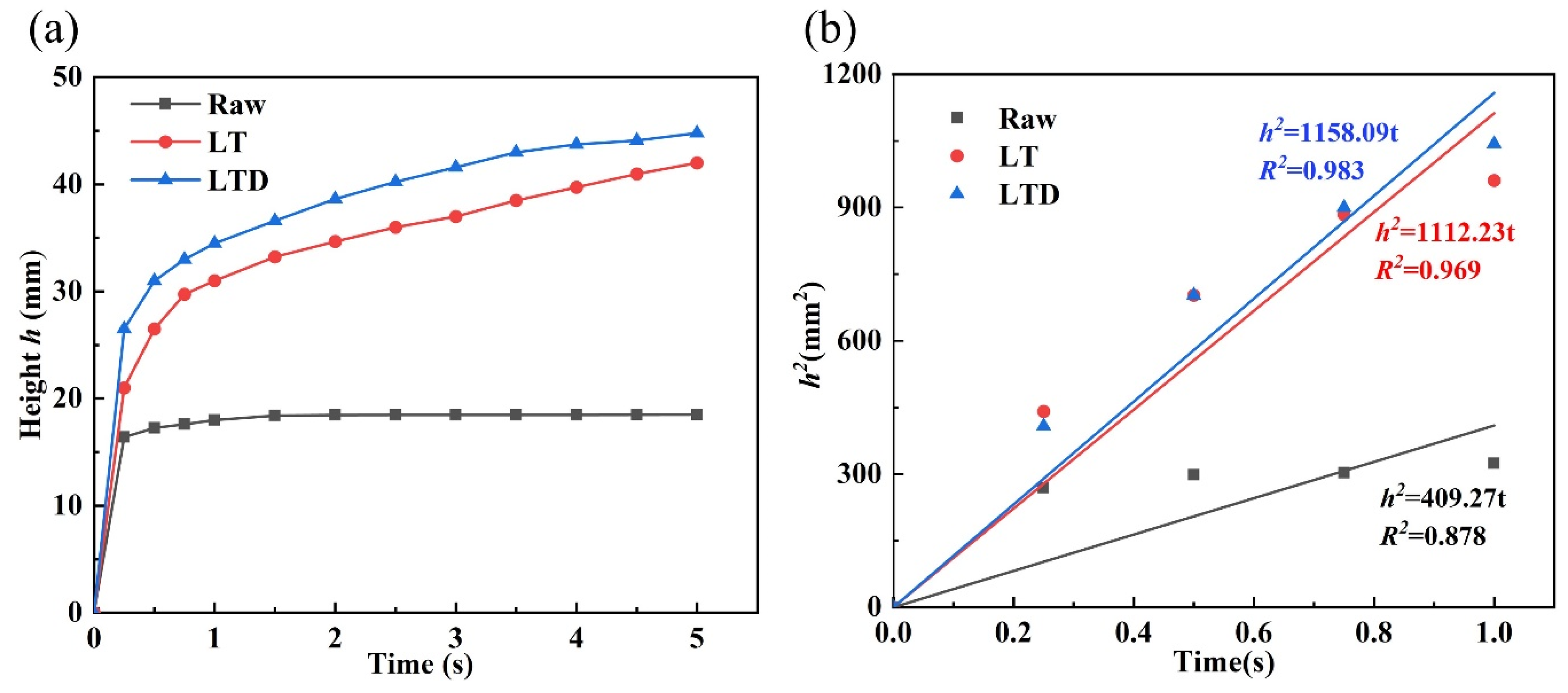
3.3. Theoretical Analysis and Capillary Rise Test

Due to the presence of a large number of fluffy structures on the surface of the LTD groove, there was a large difference in the surface morphologies of Raw and LTD grooves. The surface morphologies of different grooves were analyzed, and the Laplace–Young correlation was used for analysis (see Equation (1)) [26].
P c a p = 2 σ R e f f
where P c a p is the capillary pressure, σ is the surface tension of water, and R e f f is the effective capillary radius. It can be seen that the capillary pressure P c a p is inversely proportional to the effective capillary radius R e f f , and a change in the effective capillary radius R e f f affects the capillary pressure.
Assuming a steady state laminar flow of water in the groove and neglecting inertial forces and evaporation of water, the viscous resistance can be obtained using Equation (2) [27]:
P f = ε μ h K d h d t + ρ g h
where ρ is the density of water, g is the acceleration of gravity, ε is the porosity, μ is the dynamic viscosity of water, h is the height of water rise, K is the permeability, and d h d t is the rate of water rise.
When the effect of gravity is neglected during the initial stage of capillary rise, a combination of Equations (1) and (2) resulted in Equation (3).
2 σ R e f f = ε μ h K d h d t
When the liquid is in the process of capillary rise, the capillary pressure generated by the surface tension of the liquid is the only driving force, and the viscous and gravitational forces are the main resistance. Additionally, the rise stops when the three forces reach equilibrium [8].
When the initial condition h ( t 0 ) is met, Equation (3) becomes the Washburn equation [28], given by Equation (4).
h 2 = 4 σ ε μ K R e f f t
This paper focused on the effect of surface morphologies of different grooves on the groove capillary performance, and involves parameters such as porosity, and effective capillary radius. A parameter is needed to characterize the capillary performance. Therefore, the capillary performance factor (M) is defined using Equation (5).
M = h 2 t = 4 σ ε μ K R e f f
h 2 = M t
The capillary performance of different grooves was characterized by the value of capillary performance factor (M) in the linear phase and the rise height within 5 s. The larger the value of the capillary performance factor, the higher the rise height within 5 s, indicating stronger capillary performance of the groove.
Figure 6 shows the capillary rise curves of water for Raw, LT, and LTD grooves and the fitted straight lines for the linear phase. As shown in Figure 6a, the rise heights of LT and LTD grooves were 42 mm and 44.8 mm within 5 s, respectively. The rise height of the Raw groove was 18.5 mm within 5 s. It can be seen that the LTD groove had the highest capillary rise height, followed by LT and Raw grooves, respectively. Furthermore, the rise height of the Raw groove reached equilibrium after 1 s. The rise height of the LTD groove increased by a factor of 2.42 and a factor of 1.07 compared to that of Raw and LT grooves, respectively. As shown in Figure 6b, the h 2 t fitted straight lines for Raw, LT, and LTD grooves over 1 s had correlation coefficients of 0.878, 0.969, and 0.983, respectively. It can be seen that h 2 and t were linearly correlated for the LT and LTD grooves, while the correlation was significantly worse for the Raw groove than for LT and LTD grooves. Values for the capillary performance factor for Raw, LT, and LTD grooves were 409.27, 1112.23, and 1158.09, respectively. The value for the LTD groove was higher by 2.83 and 1.04 times than those of Raw and LT grooves, respectively. The results showed that both the LT and LTD processes significantly enhanced the capillary performance of the grooves. However, the LTD groove showed the strongest capillary performance. This is a result of the LTD SiO2 layer, which increased the fluff density on the surface of groove.
Combined with the SEM images, the microscopic model images of the surfaces of LT and LTD grooves are shown in Figure 7. The LT groove surface showed some distribution of Al2O3 fluff, which was more sparsely distributed with larger pores, resulting in lower porosity and larger effective capillary radius. A large number of mixed fluffs of Al2O3 and SiO2 were distributed on the surface of the LTD groove, which were distributed more densely. The density of fluffs in the LTD groove was significantly larger than that in the LT groove, which could increase the porosity and reduce the effective capillary radius. According to Equation (1), the LTD groove had the strongest capillary performance because of the dense fluff on the surface of the groove, which increased the capillary pressure. The capillary performance was the worst due to the fact that the Raw groove was lined with flat surfaces and there was no micro/nano pore structure to enhance the capillary pressure.

4. Conclusions

In this study, the grooves were treated using LT and LTD processes. The surface morphologies of Raw, LT, and LTD grooves were characterized using SEM. The changes in chemical composition before and after the laser processing were analyzed using XPS, and the capillary performances of Raw, LT, and LTD grooves were analyzed. Based upon the results, the following conclusions are drawn:
(1)
The formation of high surface energy oxides and porous micro/nanostructures on the surfaces of grooves treated by LT and LTD processes caused the groove surfaces to exhibit superhydrophilicity, which significantly enhanced the wettability of the grooves.
(2)
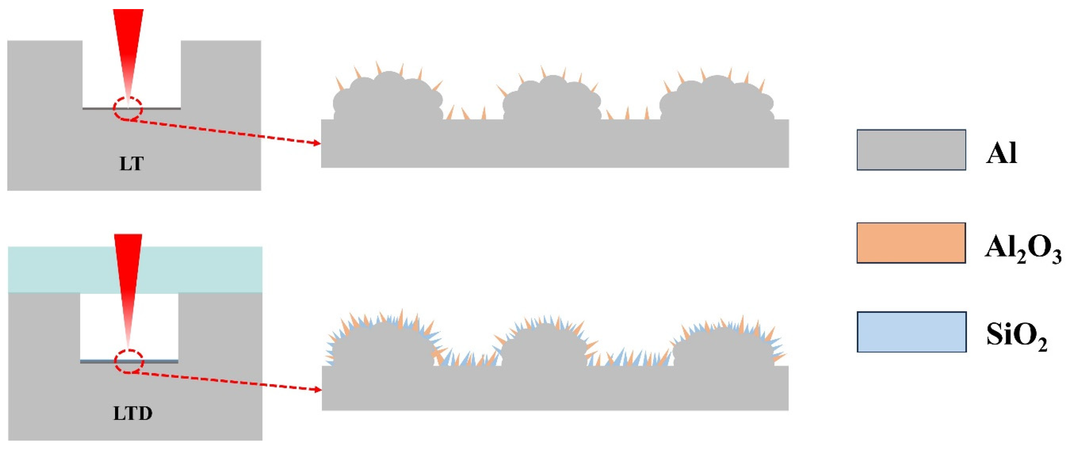
The LTD process deposited SiO2 on the surface of the groove, which formed dense fluff, resulting in an increase in porosity and a reduction in the effective capillary radius. This increased the capillary pressure of the rectangular groove and was the main reason for the enhanced capillary performance.
(3)
The rise height of the LTD groove increased by factors of 2.42 and 1.07 compared to Raw and LT grooves, respectively, whereas the capillary performance factor increased by factors of 2.83 and 1.04 compared to Raw and LT grooves, respectively.

Author Contributions

Conceptualization, D.L. (Deyuan Lou) and D.L. (Dun Liu); methodology, D.L. (Deyuan Lou); validation, D.L. (Deyuan Lou); formal analysis, D.L. (Deyuan Lou), D.Y., H.J., Q.Y. and Q.T.; investigation, D.L. (Deyuan Lou); resources, D.L. (Deyuan Lou), H.J. and Q.Y.; data curation, P.C., H.J. and D.Y.; writing—original draft preparation, P.C.; writing—review and editing, D.L. (Deyuan Lou) and P.C.; visualization, D.L. (Deyuan Lou); supervision, D.L. (Deyuan Lou) and D.L. (Dun Liu); project administration, D.L. (Deyuan Lou); funding acquisition, D.L. (Deyuan Lou) and D.L. (Dun Liu). All authors have read and agreed to the published version of the manuscript.

Funding

The research leading to these results has received financial support from Department of Science and Technology of Hubei Province Major Research and Development Project (ZDZX2020000013), National Science Foundation of China (52205148) and Open Fund of Hubei Provincial Key Laboratory of Green Materials for Light Industry (202107A03).

Data Availability Statement

The data provided in the article support the results of this study.

Conflicts of Interest

The authors have no conflict to disclose.

References

  1. Zhang, S.; Chen, C.; Chen, G.; Sun, Y.; Tang, Y.; Wang, Z. Capillary performance characterization of porous sintered stainless steel powder wicks for stainless steel heat pipes. Int. Commun. Heat Mass Transf. 2020, 116, 104702. [Google Scholar] [CrossRef]
  2. Zhang, J.; Lian, L.-X.; Liu, Y.; Wang, R.-Q. The heat transfer capability prediction of heat pipes based on capillary rise test of wicks. Int. J. Heat Mass Transf. 2021, 164, 120536. [Google Scholar] [CrossRef]
  3. Wang, H.; Wang, Q.; Huo, L.; Liu, J.; Bai, Z. High-efficient laser-based bionic surface structuring for enhanced surface functionalization and self-cleaning effect. Surf. Interfaces 2023, 37, 102691. [Google Scholar] [CrossRef]
  4. Lee, J.; So, J.; Bae, W.G.; Won, Y. The Design of Hydrophilic Nanochannel-Macrostripe Fog Collector: Enabling Wicking-Assisted Vertical Liquid Delivery for the Enhancement in Fog Collection Efficiency. Adv. Mater. Interfaces 2020, 7, 1902150. [Google Scholar] [CrossRef]
  5. Chen, H.; Ran, T.; Zhang, K.; Chen, D.; Gan, Y.; Wang, Z.; Jiang, L. Highly Efficient Multiscale Fog Collector Inspired by Sarracenia Trichome Hierarchical Structure. Glob. Chall. 2021, 5, 2100087. [Google Scholar] [CrossRef]
  6. Keshav, T.R.; Basu, S. Spreading of liquid droplets on proton exchange membrane of a direct alcohol fuel cell. Chem. Eng. Sci. 2007, 62, 7515–7522. [Google Scholar] [CrossRef]
  7. Wang, H.; He, M.; Liu, H.; Guan, Y. Controllable water behaviors on V-shape micro-grooved titanium alloy surfaces depending on the depth-to-width aspect ratio. Mater. Today Phys. 2021, 20, 100461. [Google Scholar] [CrossRef]
  8. Cai, J.; Jin, T.; Kou, J.; Zou, S.; Xiao, J.; Meng, Q. Lucas–Washburn Equation-Based Modeling of Capillary-Driven Flow in Porous Systems. Langmuir 2021, 37, 1623–1636. [Google Scholar] [CrossRef]
  9. Duan, L.; Wang, Z.; Chen, G.; Tang, Y.; Sun, Y.; Zhong, G.; Xi, X.; Xu, Y. Capillary wicking in double-scale composite microgroove wicks for copper-aluminum composite vapor chambers. Int. Commun. Heat Mass Transf. 2021, 126, 105449. [Google Scholar] [CrossRef]
  10. Laguna, G.; Vilarrubí, M.; Ibañez, M.; Betancourt, Y.; Illa, J.; Azarkish, H.; Amnache, A.; Collin, L.-M.; Coudrain, P.; Fréchette, L.; et al. Numerical parametric study of a hotspot-targeted microfluidic cooling array for microelectronics. Appl. Therm. Eng. 2018, 144, 71–80. [Google Scholar] [CrossRef]
  11. Huang, G.; Liu, W.; Luo, Y.; Li, Y.; Chen, H. Fabrication and capillary performance of a novel composite wick for ultra-thin heat pipes. Int. J. Heat Mass Transf. 2021, 176, 121467. [Google Scholar] [CrossRef]
  12. Gukeh, M.J.; Damoulakis, G.; Megaridis, C.M. Low-profile heat pipe consisting of wick-lined and non-adiabatic wickless wettability-patterned surfaces. Appl. Therm. Eng. 2022, 211, 118433. [Google Scholar] [CrossRef]
  13. Zhou, W.; Li, Y.; Chen, Z.; Deng, L.; Gan, Y. A novel ultra-thin flattened heat pipe with biporous spiral woven mesh wick for cooling electronic devices. Energy Convers. Manag. 2019, 180, 769–783. [Google Scholar] [CrossRef]
  14. Chen, G.; Fan, D.; Zhang, S.; Sun, Y.; Zhong, G.; Wang, Z.; Wan, Z.; Tang, Y. Wicking capability evaluation of multilayer composite micromesh wicks for ultrathin two-phase heat transfer devices. Renew. Energy 2021, 163, 921–929. [Google Scholar] [CrossRef]
  15. Dai, X.; Yang, F.; Yang, R.; Lee, Y.C.; Li, C. Micromembrane-enhanced capillary evaporation. Int. J. Heat Mass Transf. 2013, 64, 1101–1108. [Google Scholar] [CrossRef]
  16. Deng, D.; Tang, Y.; Huang, G.; Lu, L.; Yuan, D. Characterization of capillary performance of composite wicks for two-phase heat transfer devices. Int. J. Heat Mass Transf. 2013, 56, 283–293. [Google Scholar] [CrossRef]
  17. Zhong, G.; Tang, Y.; Ding, X.; Chen, G.; Li, Z. Experimental investigation on wettability and capillary performance of ultrasonic modified grooved aluminum wicks. Int. J. Heat Mass Transf. 2021, 179, 121642. [Google Scholar] [CrossRef]
  18. Niu, J.; Xie, N.; Gao, X.; Fang, Y.; Zhang, Z. Capillary performance analysis of copper powder-fiber composite wick for ultra-thin heat pipe. Heat Mass Transf. 2020, 57, 949–960. [Google Scholar] [CrossRef]
  19. Huang, G.; Yuan, W.; Tang, Y.; Zhang, B.; Zhang, S.; Lu, L. Enhanced capillary performance in axially grooved aluminium wicks by alkaline corrosion treatment. Exp. Therm. Fluid Sci. 2017, 82, 212–221. [Google Scholar] [CrossRef]
  20. Xie, D.; Sun, Y.; Wang, G.; Chen, S.; Ding, G. Significant factors affecting heat transfer performance of vapor chamber and strategies to promote it: A critical review. Int. J. Heat Mass Transf. 2021, 175, 121132. [Google Scholar] [CrossRef]
  21. Li, J.; Zhang, M. Enhanced capillary performance of grooved nanocarbon foams as wicks for heat pipes. Int. Commun. Heat Mass Transf. 2022, 130, 105763. [Google Scholar] [CrossRef]
  22. Liu, T.; Yan, W.; Wu, W.; Wang, S. Thermal performance enhancement of vapor chamber with modified thin screen mesh wick by laser etching. Case Stud. Therm. Eng. 2021, 28, 101525. [Google Scholar] [CrossRef]
  23. Long, J.; Chu, P.; Li, Y.; Lin, J.; Cao, Z.; Xu, M.; Ren, Q.; Xie, X. Dual-scale porous/grooved microstructures prepared by nanosecond laser surface texturing for high-performance vapor chambers. J. Manuf. Process. 2022, 73, 914–923. [Google Scholar] [CrossRef]
  24. Jiang, G.; Tian, Z.; Luo, X.; Chen, C.; Hu, X.; Wang, L.; Peng, R.; Zhang, H.; Zhong, M. Ultrathin aluminum wick with dual-scale microgrooves for enhanced capillary performance. Int. J. Heat Mass Transf. 2022, 190, 122762. [Google Scholar] [CrossRef]
  25. Wu, C.; Tang, Y.; Zhang, S.; Yuan, X.; Yan, C.; Tang, H. Analytical and experimental on the capillary rise of aluminum multi-scale microgroove wick structures. Phys. Fluids 2023, 35, 052016. [Google Scholar] [CrossRef]
  26. Tang, H.; Tang, Y.; Yuan, W.; Peng, R.; Lu, L.; Wan, Z. Fabrication and capillary characterization of axially micro-grooved wicks for aluminium flat-plate heat pipes. Appl. Therm. Eng. 2018, 129, 907–915. [Google Scholar] [CrossRef]
  27. Espinosa, F.D.; Peters, T.B.; Brisson, J.G. Effect of fabrication parameters on the thermophysical properties of sintered wicks for heat pipe applications. Int. J. Heat Mass Transf. 2012, 55, 7471–7486. [Google Scholar] [CrossRef]
  28. Weislogel, M.M. Compound capillary rise. J. Fluid Mech. 2012, 709, 622–647. [Google Scholar] [CrossRef]
Figure 1. (a) Geometry of the Raw groove, (b) LT groove prepared schematic, (c) LTD groove prepared schematic.
Crystals 13 01397 g001
Figure 2. 3D images of different grooves: (a) Raw groove, (b) LT groove, (c) LTD groove.
Crystals 13 01397 g002
Figure 3. Capillary rise experimental setup (The length of the ruler is 10 cm).
Crystals 13 01397 g003
Figure 4. Grayscale and SEM images of three surfaces: (a) Raw; (b) LT; (c) LTD.
Crystals 13 01397 g004aCrystals 13 01397 g004b
Figure 5. XPS spectra of three different samples: (a) Full spectrum, (b) Raw sample, (c) LT sample, (d) LTD sample, (e) LTD sample.
Crystals 13 01397 g005
Figure 6. Capillary behavior of different grooves: (a) Capillary rise curve; (b) Linear phase of h 2 t fitting straight lines.
Crystals 13 01397 g006
Figure 7. Microscopic modeling diagrams of LT and LTD groove surfaces.
Crystals 13 01397 g007
Table 1. Laser processing parameters.
WavelengthPulse WidthRepeat FrequencyLaser Energy DensitySpeed
1064 nm230 ns140 kHz35.3 J/cm21400 mm/s
Table 2. The surface elemental content of the three samples was measured by XPS.
Wt%AlOSiMg
Raw36.9161.9701.13
LT30.5768.4400.98
LTD11.1975.1913.070.54
Disclaimer/Publisher’s Note: The statements, opinions and data contained in all publications are solely those of the individual author(s) and contributor(s) and not of MDPI and/or the editor(s). MDPI and/or the editor(s) disclaim responsibility for any injury to people or property resulting from any ideas, methods, instructions or products referred to in the content.

