
A Study on Metallographic and Machining Characteristics of Functionally Graded Material Produced by Directed Energy Deposition


Abstract
:1. Introduction
2. DED for FGM Experiments
2.1. Powders
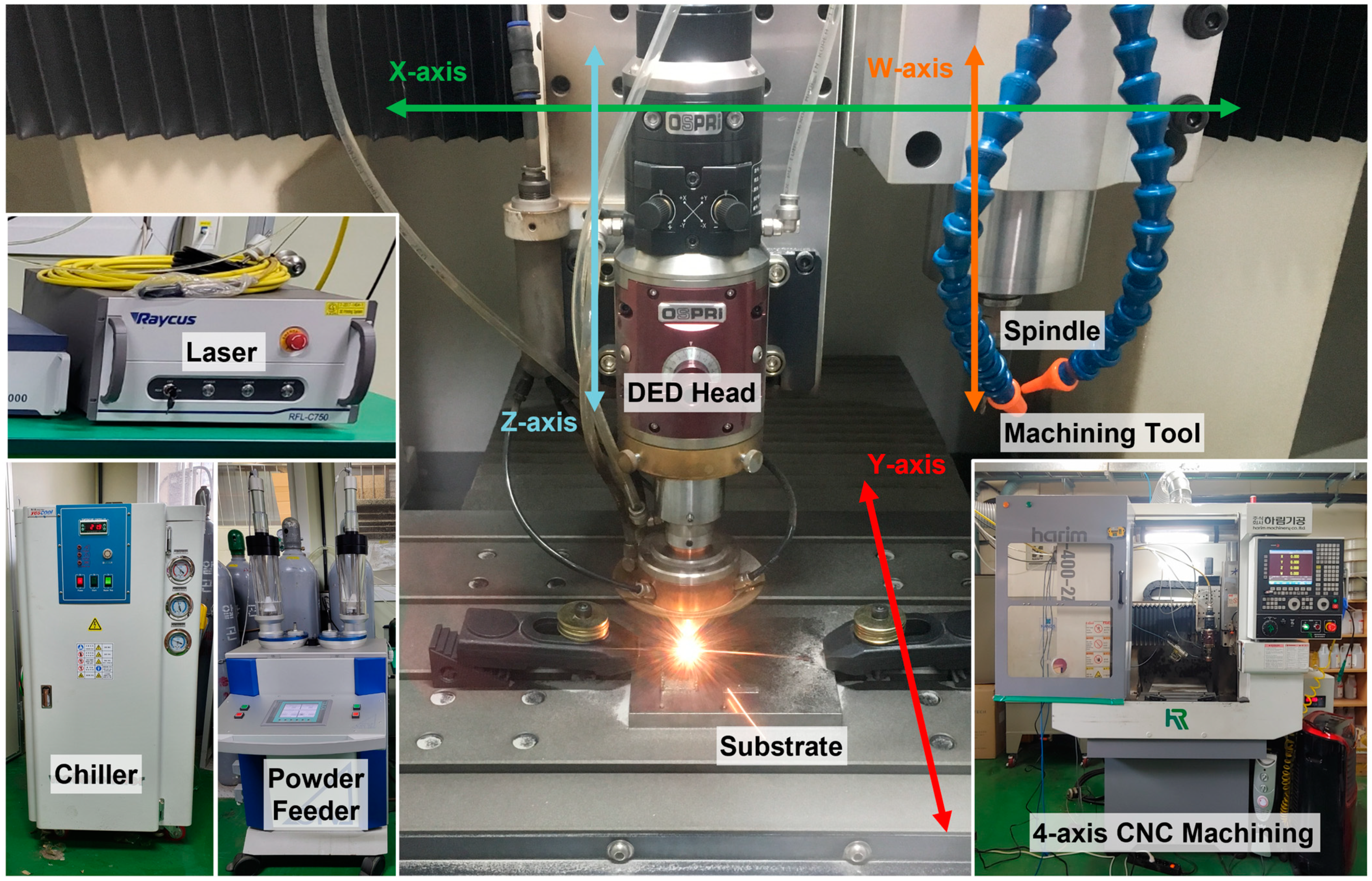
2.2. Experimental Testbed
2.3. Experimental Design and Conditions
3. Metallographic Characteristics
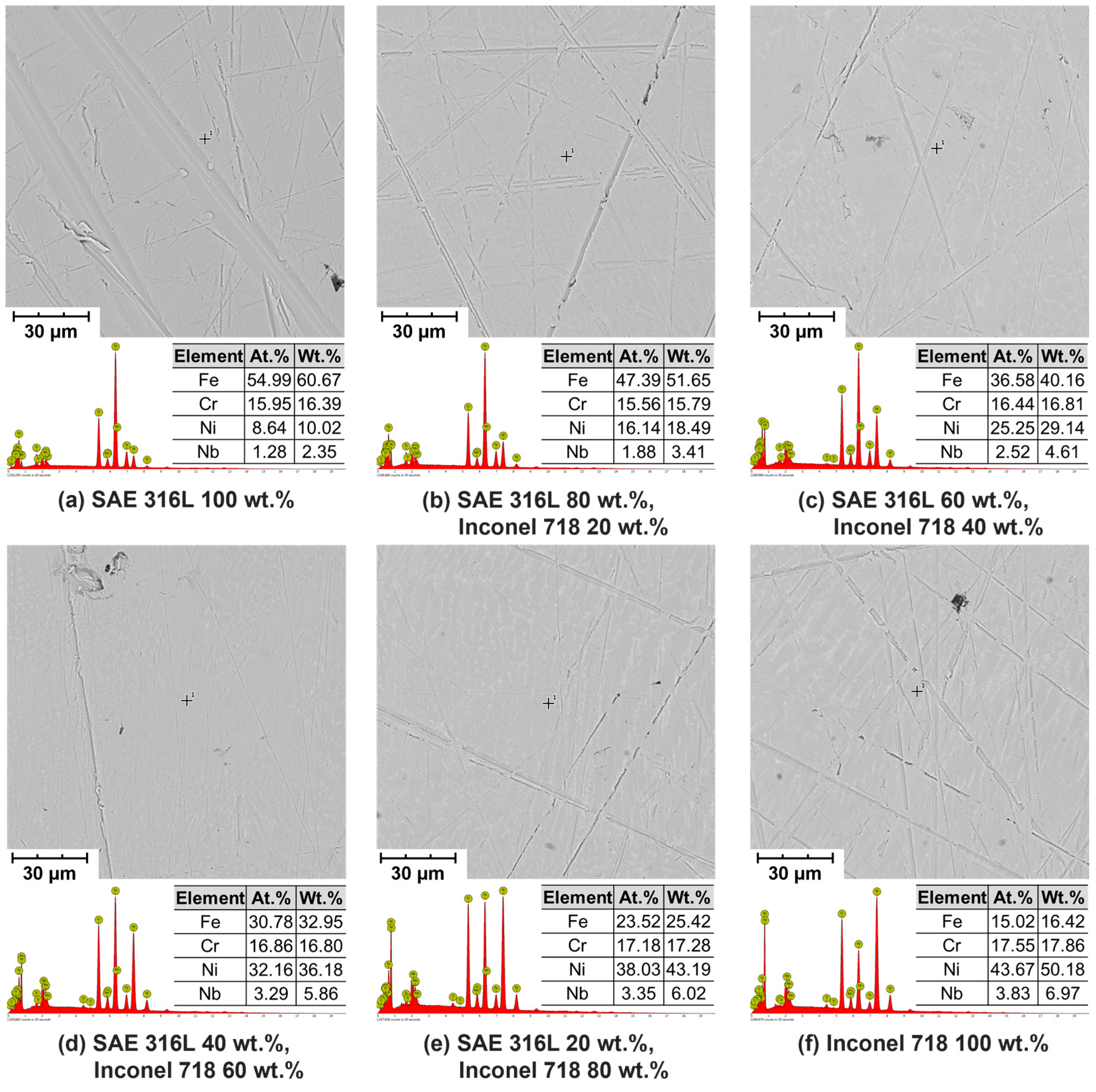
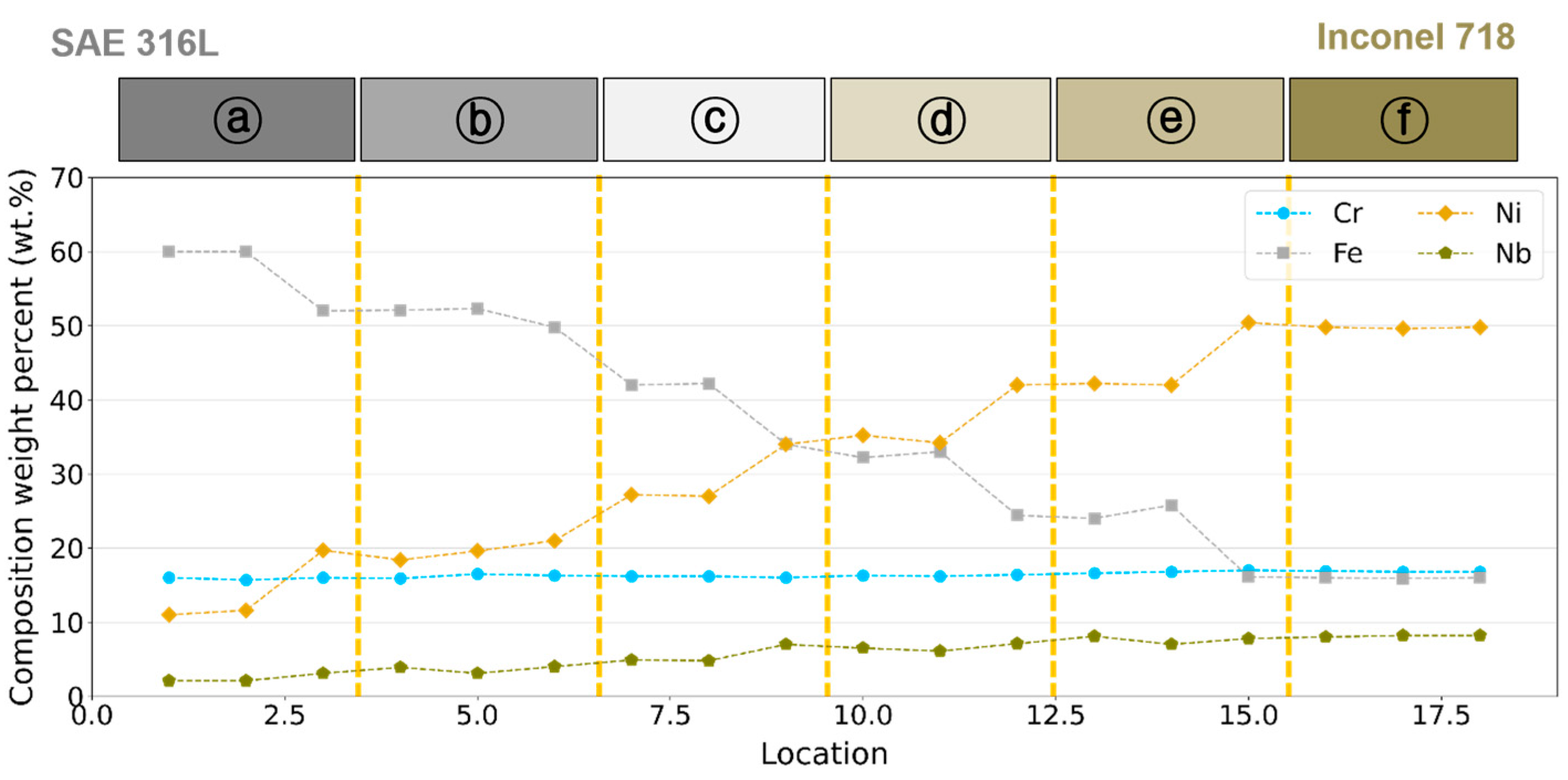
3.1. Compositions
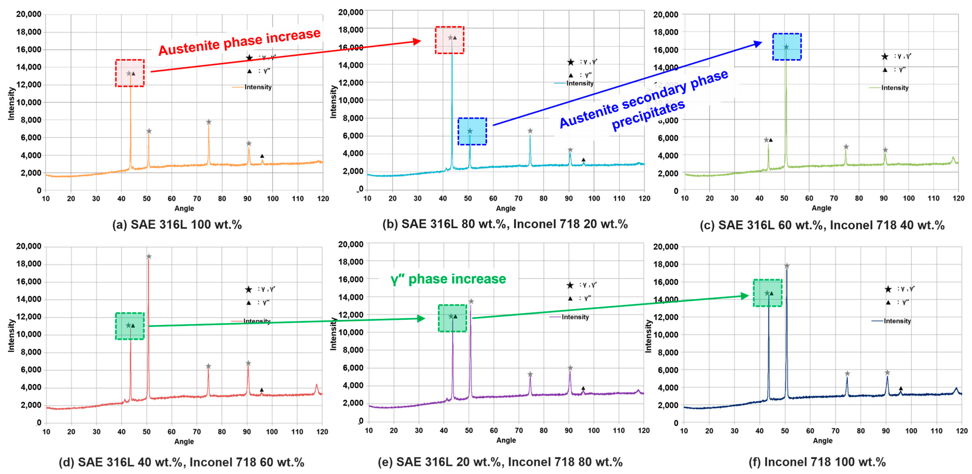
3.2. Microstructure
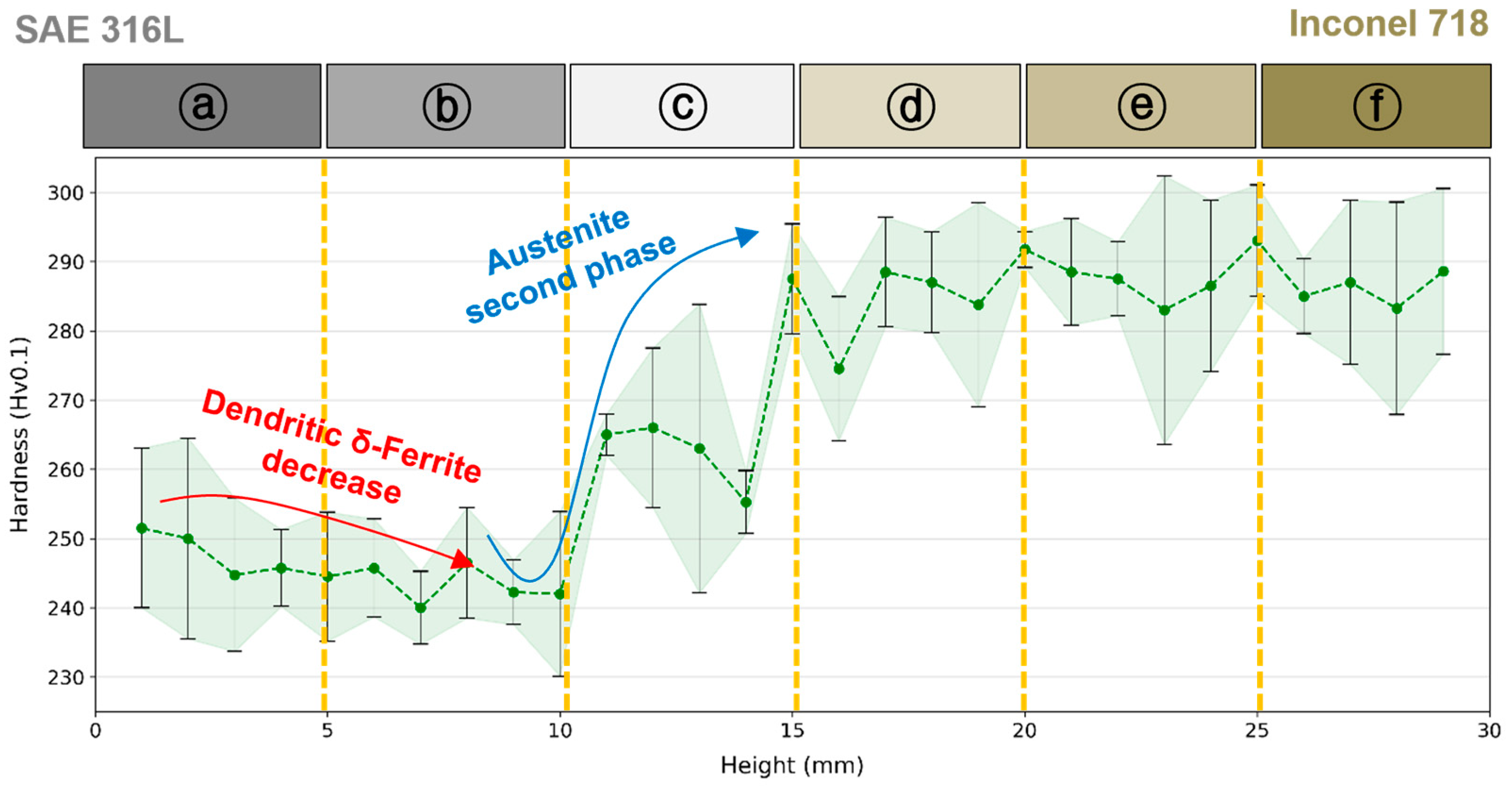
3.3. Mechanical Properties
4. Machining Characteristics
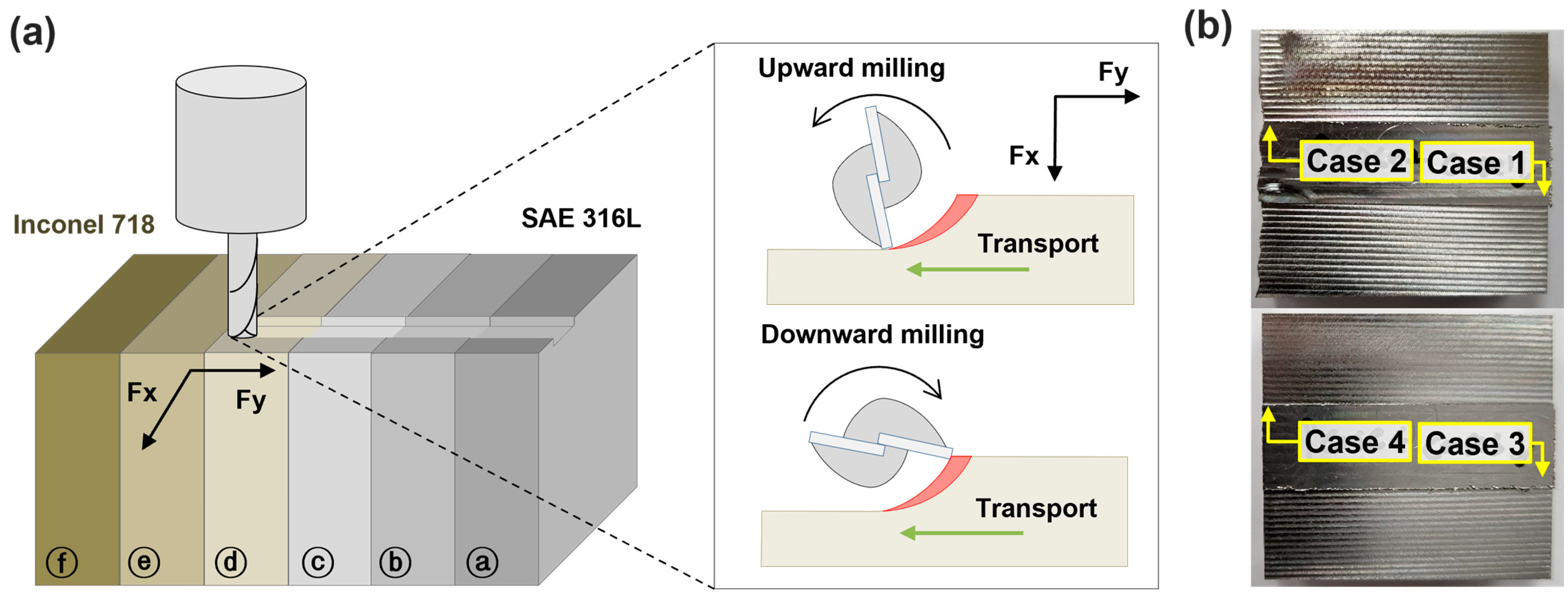
4.1. Milling Experiments
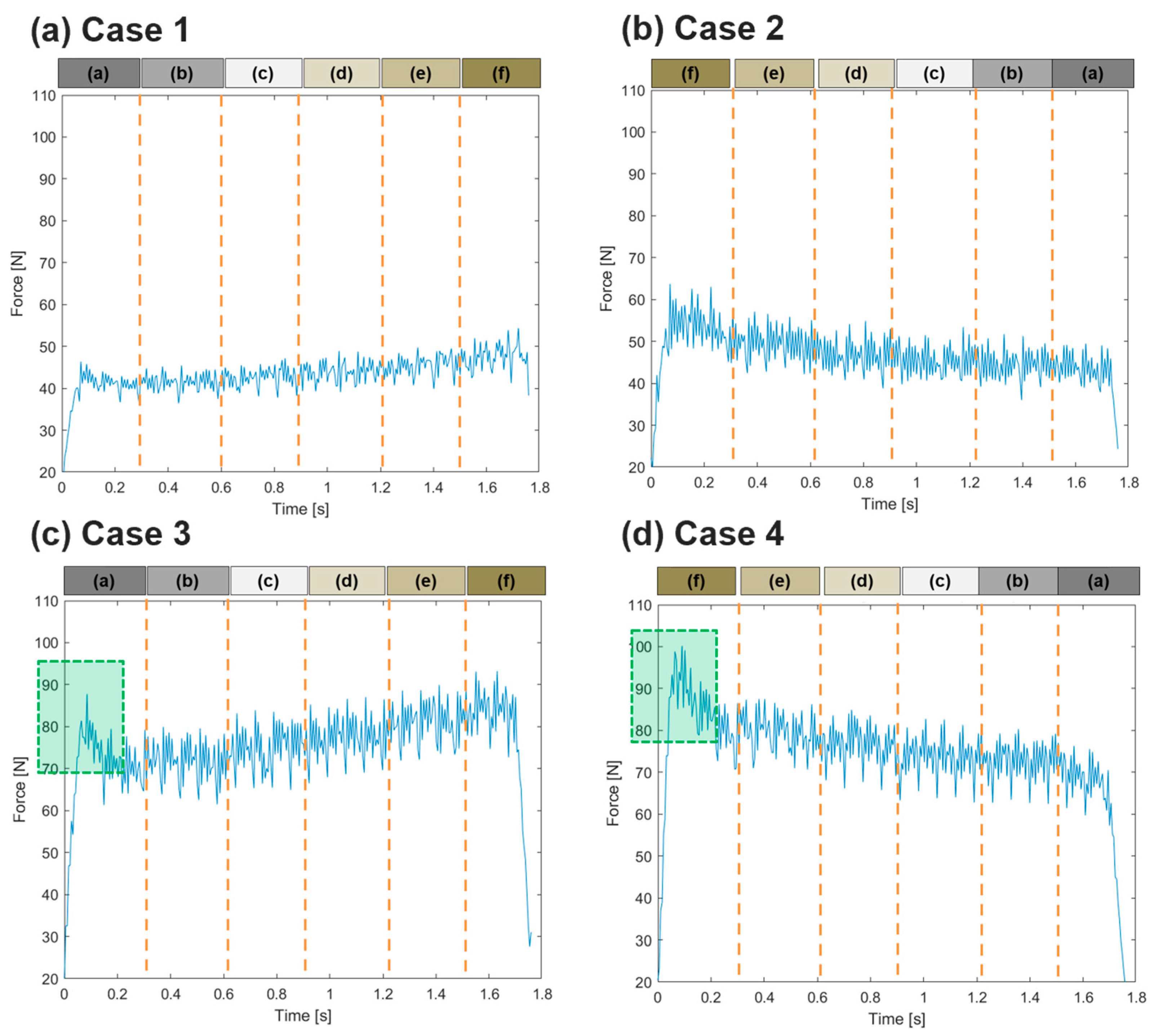
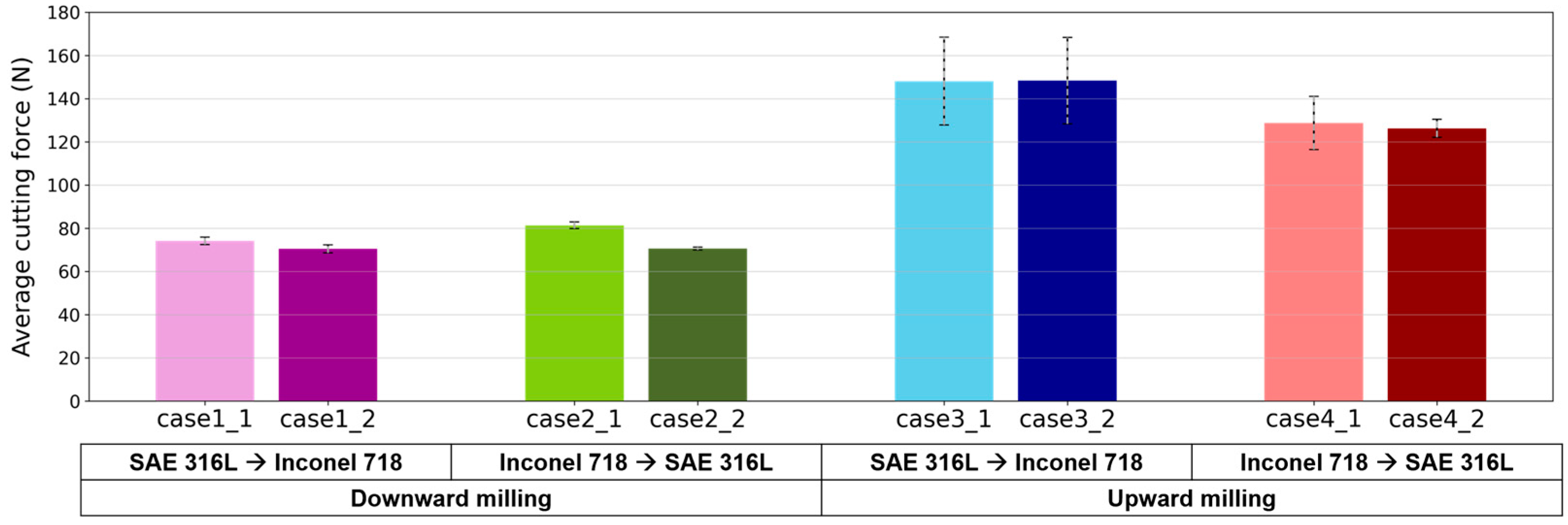
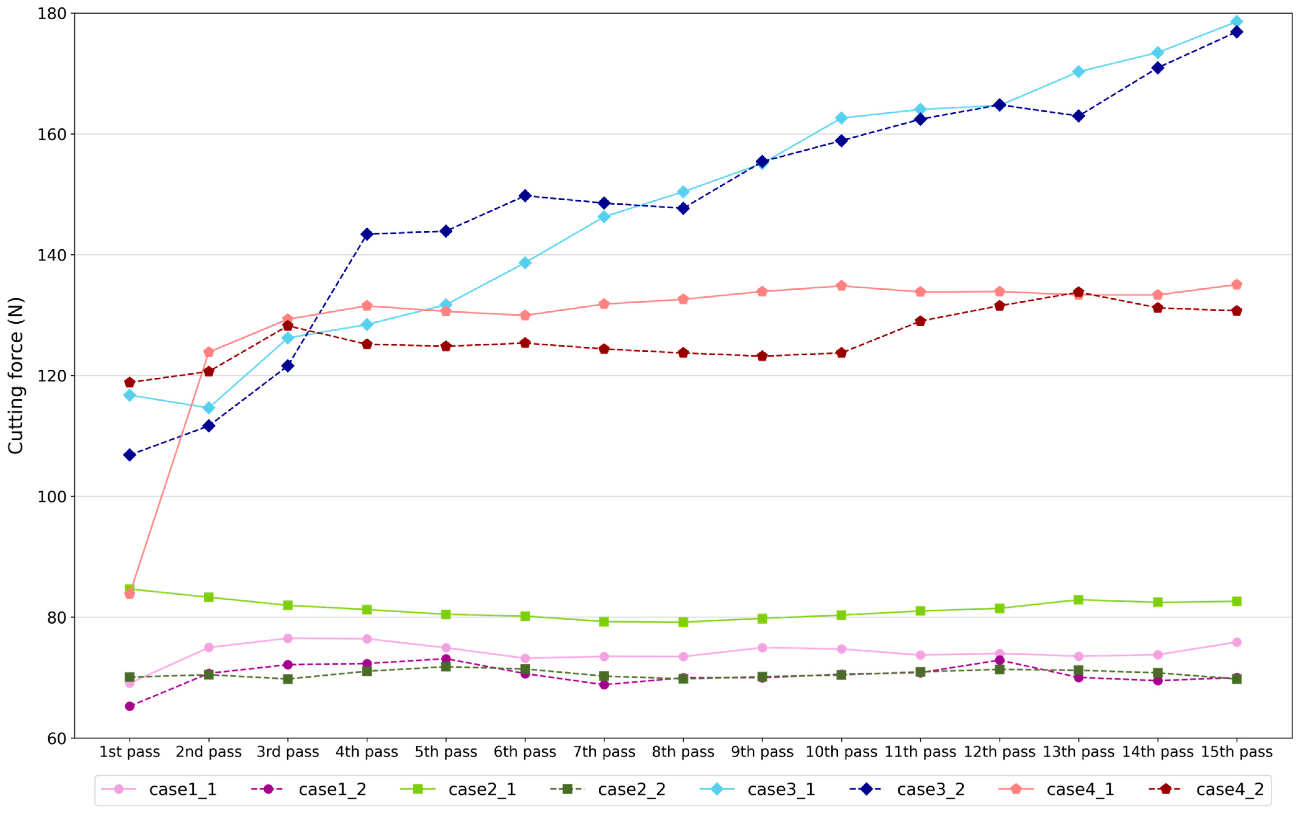
4.2. Cutting Force
4.3. Tool Wear
5. Conclusions
Author Contributions
Funding
Data Availability Statement
Conflicts of Interest
References
- Guo, N.; Leu, M.C. Additive manufacturing: Technology, applications and research needs. Front. Mech. Eng. 2013, 8, 215–243. [Google Scholar] [CrossRef]
- Wong, K.V.; Hernandez, A. A review of additive manufacturing. Int. Sch. Res. Not. 2012, 2012, 1–10. [Google Scholar] [CrossRef]
- Frazier, W.E. Metal additive manufacturing: A review. J. Mater. Eng. Perform. 2014, 23, 1917–1928. [Google Scholar] [CrossRef]
- Mellor, S.; Hao, L.; Zhang, D. Additive manufacturing: A framework for implementation. Int. J. Prod. Econ. 2014, 149, 194–201. [Google Scholar] [CrossRef]
- Dilberoglu, U.M.; Gharehpapagh, B.; Yaman, U.; Dolen, M. The role of additive manufacturing in the era of industry 4.0. Procedia Manuf. 2017, 11, 545–554. [Google Scholar] [CrossRef]
- Ahn, D.G. Direct metal additive manufacturing processes and their sustainable applications for green technology: A review. Int. J. Precis. Eng. Manuf. Green Technol. 2016, 3, 381–395. [Google Scholar] [CrossRef]
- Kim, J.S.; Kang, B.J.; Lee, S.W. An experimental study on microstructural characteristics and mechanical properties of stainless-steel 316L parts using directed energy deposition (DED) process. J. Mech. Sci. Technol. 2019, 33, 5731–5737. [Google Scholar] [CrossRef]
- Duda, T.; Raghavan, L.V. 3D metal printing technology. IFAC Pap. 2016, 49, 103–110. [Google Scholar] [CrossRef]
- Saboori, A.; Aversa, A.; Marchese, G.; Biamino, S.; Lombardi, M.; Fino, P. Application of directed energy deposition-based additive manufacturing in repair. Appl. Sci. 2019, 9, 3316. [Google Scholar] [CrossRef]
- Loh, G.H.; Pei, E.; Harrison, D.; Monzón, M.D. An overview of functionally graded additive manufacturing. Addit. Manuf. 2018, 23, 34–44. [Google Scholar] [CrossRef]
- Zhao, K.; Zhang, G.; Ma, G.; Shen, C.; Wu, D. Microstructure and mechanical properties of titanium alloy/zirconia functionally graded materials prepared by laser additive manufacturing. J. Manuf. Process. 2020, 56, 616–622. [Google Scholar] [CrossRef]
- Geng, Y.; Xie, W.; Tu, Y.; Deng, S.; Egan, D.; Dowling, D.P.; Song, H.; Zhang, S.; Harrison, N. Ti–6Al–4V microstructural functionally graded material by additive manufacturing: Experiment and computational modelling. Mater. Sci. Eng. A 2021, 823, 141782. [Google Scholar] [CrossRef]
- Rani, K.U.; Kumar, R.; Mahapatra, M.M.; Mulik, R.S.; Świerczyńska, A.; Fydrych, D.; Pandey, C. Wire arc additive manufactured mild steel and austenitic stainless steel components: Microstructure, mechanical properties and residual stresses. Materials 2022, 15, 7094. [Google Scholar] [CrossRef] [PubMed]
- Sanjeeviprakash, K.; Kannan, A.R.; Shanmugam, N.S. Additive manufacturing of metal-based functionally graded materials: Overview, recent advancements and challenges. J. Braz. Soc. Mech. Sci. Eng. 2023, 45, 241. [Google Scholar] [CrossRef]
- Liverani, E.; Fortunato, A. Additive manufacturing of AISI 420 stainless steel: Process validation, defect analysis and mechanical characterization in different process and post-process conditions. Int. J. Adv. Manuf. Technol. 2021, 117, 809–821. [Google Scholar] [CrossRef]
- Fan, W.; Zhang, C.; Tan, H.; Wang, Y.; Peng, Y.; Zhang, F.; Lin, X.; Huang, W. Microstructures and mechanical properties of Invar/MnCu functionally graded material fabricated by directed energy deposition. Mater. Sci. Eng. A 2022, 860, 144332. [Google Scholar] [CrossRef]
- Su, Y.; Chen, B.; Tan, C.; Song, X.; Feng, J. Influence of composition gradient variation on the microstructure and mechanical properties of 316 L/Inconel718 functionally graded material fabricated by laser additive manufacturing. J. Mater. Process. Technol. 2020, 283, 116702. [Google Scholar] [CrossRef]
- Zhang, X.; Chen, Y.; Liou, F. Fabrication of SS316L-IN625 functionally graded materials by powder-fed directed energy deposition. Sci. Technol. Weld. Join. 2019, 24, 504–516. [Google Scholar] [CrossRef]
- Rodrigues, T.A.; Farias, F.W.C.; Zhang, K.; Shamsolhodaei, A.; Shen, J.; Zhou, N.; Schell, N.; Capek, J.; Polatidis, E.; Santos, T.G.; et al. Wire and arc additive manufacturing of 316L stainless steel/Inconel 625 functionally graded material: Development and characterization. J. Mater. Res. Technol. 2022, 21, 237–251. [Google Scholar] [CrossRef]
- Yu, X.; Xue, J.; Shen, Q.; Zheng, Z.; Ou, N.; Wu, W. Dual-wire plasma arc additively manufactured SS 316l-Inconel 625 functionally graded material: Microstructure Evolution and mechanical properties. J. Mater. Eng. Perform. 2023, 32, 1412–1422. [Google Scholar] [CrossRef]
- Kim, S.H.; Lee, H.; Yeon, S.M.; Aranas, C., Jr.; Choi, K.; Yoon, J.; Yang, S.W.; Lee, H. Selective compositional range exclusion via directed energy deposition to produce a defect-free Inconel 718/SS 316L functionally graded material. Addit. Manuf. 2021, 47, 102288. [Google Scholar] [CrossRef]
- Li, T.; Wang, Z.; Hu, S.; Yang, Z.; Wang, Y. Hot cracking during the fabrication of Inconel 625/stainless steel 308 L functionally graded material by dual-wire arc additive manufacturing. J. Manuf. Process. 2022, 82, 461–473. [Google Scholar] [CrossRef]
- Yang, S.W.; Yoon, J.; Lee, H.; Shim, D.S. Defect of functionally graded material of inconel 718 and STS 316L fabricated by directed energy deposition and its effect on mechanical properties. J. Mater. Res. Technol. 2022, 17, 478–497. [Google Scholar] [CrossRef]
- Carroll, B.E.; Otis, R.A.; Borgonia, J.P.; Suh, J.O.; Dillon, R.P.; Shapiro, A.A.; Hofmann, D.C.; Liu, Z.K.; Beese, A.M. Functionally graded material of 304L stainless steel and inconel 625 fabricated by directed energy deposition: Characterization and thermodynamic modeling. Acta Mater. 2016, 108, 46–54. [Google Scholar] [CrossRef]
- Venkatachalam, A.; Anurag, P.V.S.; Sadanand, T.D.; Nachimuthu, R. Optimization of the milling parameters for an Al/Si3N4 functionally graded composite using grey relational analysis. Mater. Test. 2018, 60, 215–221. [Google Scholar] [CrossRef]
- Liu, D.; Liu, Z.; Zhao, J.; Song, Q.; Ren, X.; Ma, H. Tool wear monitoring through online measured cutting force and cutting temperature during face milling Inconel 718. Int. J. Adv. Manuf. Technol. 2022, 122, 729–740. [Google Scholar] [CrossRef]
- Martyushev, N.V.; Kozlov, V.N.; Qi, M.; Tynchenko, V.S.; Kononenko, R.V.; Konyukhov, V.Y.; Valuev, D.V. Production of Workpieces from Martensitic Stainless Steel Using Electron-Beam Surfacing and Investigation of Cutting Forces when Milling Workpieces. Materials 2023, 16, 4529. [Google Scholar] [CrossRef]
- Oyelola, O.; Crawforth, P.; M’Saoubi, R.; Clare, A.T. Machining of functionally graded Ti6Al4V/WC produced by directed energy deposition. Addit. Manuf. 2018, 24, 20–29. [Google Scholar] [CrossRef]
- Levano Blanch, O.; Suárez Fernández, D.; Graves, A.; Jackson, M. Mul Ti-FAST: A Machinability Assessment of Functionally Graded Titanium Billets Produced from Multiple Alloy Powders. Materials 2022, 15, 3237. [Google Scholar] [CrossRef]
- Wang, C.; Ge, Y.; Ma, J.; Yu, Z.; Zhang, K.; Liu, T.; Guo, X.; Huang, S. Effects of parameter selection strategy on tool wear when milling 3D-printed functionally graded materials with textured tool under minimum quantity lubrication. Int. J. Adv. Manuf. Technol. 2023, 125, 1615–1632. [Google Scholar] [CrossRef]
- Feenstra, D.R.; Cruz, V.; Gao, X.; Molotnikov, A.; Birbilis, N. Effect of build height on the properties of large format stainless steel 316L fabricated via directed energy deposition. Addit. Manuf. 2020, 34, 101205. [Google Scholar] [CrossRef]
- Zhang, Q.L.; Yao, J.H.; Mazumder, J. Laser direct metal deposition technology and microstructure and composition segregation of Inconel 718 superalloy. J. Iron Steel Res. Int. 2011, 18, 73–78. [Google Scholar] [CrossRef]
- Yan, S.; Wang, Y.; Wang, Q.; Zhang, C.; Chen, D.; Cui, G. Enhancing mechanical properties of the spark plasma sintered Inconel 718 alloy by controlling the nano-scale precipitations. Materials 2019, 12, 3336. [Google Scholar] [CrossRef] [PubMed]
- Guiraldenq, P.; Duparc, O.H. The genesis of the Schaeffler diagram in the history of stainless steel. Metall. Res. Technol. 2017, 114, 613. [Google Scholar] [CrossRef]
- Fortan, M.; Dejans, A.; Debruyne, D.; Rossi, B. The strength of stainless steel fillet welds using GMAW. In Proceedings of the Stainless Steel in Structures: Fifth International Experts Seminar, London, UK, 18–19 September 2017; pp. 1–13. [Google Scholar]
- Liverani, E.; Toschi, S.; Ceschini, L.; Fortunato, A. Effect of selective laser melting (SLM) process parameters on microstructure and mechanical properties of 316L austenitic stainless steel. J. Mater. Process. Technol. 2017, 249, 255–263. [Google Scholar] [CrossRef]
- Manikandan, S.G.K.; Sivakumar, D.; Rao, K.P.; Kamaraj, M. Effect of weld cooling rate on Laves phase formation in Inconel 718 fusion zone. J. Mater. Process. Technol. 2014, 214, 358–364. [Google Scholar] [CrossRef]


| Element (wt.%) | Fe | Ni | Cr | Mn | Si | C | Mo | Nb | Ti | Others |
|---|---|---|---|---|---|---|---|---|---|---|
| SAE 316L powder | Bal. | 12 | 17 | 2.3 | 2.3 | 0.03 | - | - | - | ≤0.5 |
| Inconel 718 powder | 18 | Bal. | 19 | - | - | - | 3 | 5 | 1 | ≤1.0 |
| AISI 1045 substrate | Bal. | - | - | - | 0.7 | 0.45 | - | - | - | - |
| Composition Percentage (wt.%) | Laser Power (W) | Scanning Speed (mm/min) | Mass Flow Rate of Powder (g/min) | Flow Rate of Delivery Gas (L/min) | Flow Rate of Shielding Gas (L/min) | DED Head Distance to Substrate (mm) | Overlap (%) |
|---|---|---|---|---|---|---|---|
| 20 | 300 | 465 | 10 | 14 | 14 | 10 | 31 |
| Spindle Speed 1 (RPM) | Feed Rate 2 (mm/min) | Feed per Tooth 3 (mm/Tooth) |
|---|---|---|
| 5305 | 955 | 0.09 |
| Case | Milling Method | Milling Path |
|---|---|---|
| Case 1 | Downward milling | SAE 316L → Inconel 718 |
| Case 2 | Downward milling | Inconel 718 → SAE 316L |
| Case 3 | Upward milling | SAE 316L → Inconel 718 |
| Case 4 | Upward milling | Inconel 718 → SAE 316L |
Disclaimer/Publisher’s Note: The statements, opinions and data contained in all publications are solely those of the individual author(s) and contributor(s) and not of MDPI and/or the editor(s). MDPI and/or the editor(s) disclaim responsibility for any injury to people or property resulting from any ideas, methods, instructions or products referred to in the content. |
© 2023 by the authors. Licensee MDPI, Basel, Switzerland. This article is an open access article distributed under the terms and conditions of the Creative Commons Attribution (CC BY) license (https://creativecommons.org/licenses/by/4.0/).
Share and Cite
Noh, I.; Jeon, J.; Lee, S.W. A Study on Metallographic and Machining Characteristics of Functionally Graded Material Produced by Directed Energy Deposition. Crystals 2023, 13, 1491. https://doi.org/10.3390/cryst13101491
Noh I, Jeon J, Lee SW. A Study on Metallographic and Machining Characteristics of Functionally Graded Material Produced by Directed Energy Deposition. Crystals. 2023; 13(10):1491. https://doi.org/10.3390/cryst13101491
Chicago/Turabian StyleNoh, Inwoong, Jaehun Jeon, and Sang Won Lee. 2023. "A Study on Metallographic and Machining Characteristics of Functionally Graded Material Produced by Directed Energy Deposition" Crystals 13, no. 10: 1491. https://doi.org/10.3390/cryst13101491
APA StyleNoh, I., Jeon, J., & Lee, S. W. (2023). A Study on Metallographic and Machining Characteristics of Functionally Graded Material Produced by Directed Energy Deposition. Crystals, 13(10), 1491. https://doi.org/10.3390/cryst13101491