Abstract
An innovative 2D-material, graphocrown, was designed and studied. Our graphocrown computations revealed a higher stability compared to previous materials studied with the same generalized C2O formula. The energetic benefit of the graphocrown formation from benzenehexol was also evaluated. The structure and properties of graphocrowns with various layer arrangements were analysed and compared. In addition, the formation of potassium complexes with the new material was studied. It was found that graphocrown binds potassium better than 18-crown-6, and the intercalation of graphocrown with potassium is more favourable, compared to graphite. Finally, the band structure, as well as the mobility of the charge carriers in the graphocrown, were investigated.
1. Introduction
The design of promising materials is key to the development of applied science and technology [1]. One such material is graphene, whose theoretical research was initiated by P.R. Wallace in 1947, long before any real samples of the material were available [2]. The unique properties of graphene, predicted and then derived from experiments such as unusual thermal conductivity [3], high electron mobility [4,5], and optical transparency [6] gave a big jump-start to the development of electronics [7]. The graphene family can now be implemented in a wide range of applications in photovoltaics [8] and photodetection [9], painting [10] and sensing [11], drug delivery [12] and medicine [13]. However, unmodified graphene is a semi-metal with a zero gap, and has an extremely low on/off current ratio, which prevents it from being used in semiconductor devices such as field-effect transistors and logic circuits [14]. One of the approaches for tuning the electronic properties would be the introducing of heteroatoms—the formation of heterographenes [15]. For the first period (where the atoms match well the size of carbon and each other), there are several observed or predicted regular 2D materials—g-C3N4, [16] CB [17] and h-BN [18]. At the same time, carbon oxygenates are of much less interest, except for graphene oxide [19]—a mysterious irregular material with a not-fully understood structure. However, strong oxidising agents lead to the destruction of the p-p conjugation of the sp2 carbon network, and to a loss of conductivity in graphene oxides [20]. In addition, the inevitable heterogeneities and defects arising from the chemical modification of graphene can lead to the inevitable loss of the expected properties of the final materials [21]. The irregular distribution of functional groups and coordination centres can also have a negative impact on the properties of graphene oxide/metal composites [22].
Another approach to developing materials is to use relatively simple oxocarbon molecules as a starting structure [23]. The enormous variability in structures/properties of the oxocarbon molecules opens up excellent prospects for the development of materials for electronics engineering that will surpass their existing analogues [24,25,26]. One of the first such materials was graphether, a new two-dimensional oxocarbon that could be synthesised by assembling dimethyl ether molecules [27]. The graphether had superior thermodynamic stability, a direct bandgap of 2.39 eV and strong light absorption in the UV region [28]. Further investigating the graphether-based nanoribbon, it was found that symmetry plays a key role in the band structure, which can cause an indirect–direct bandgap transition, following parity-oddness in nanoribbons [29]. However, more complex symmetric oxocarbons are not known yet, nor are the coordination properties directly related to their structure.
Inspired by graphether, as well as the coordination properties of crown ethers [30,31], in particular integrated into the graphene flaxes [32,33], we decided to combine these concepts and developed a covalent organic framework (COF) that would consist of graphene-planar crown ethers—the graphocrown. One of the key features of the new material is its preorganisation and fixed pore size. This is particularly important in the fields of selective membrane engineering [34], extraction [35], and catalysis [36]. Graphocrown could theoretically be used more successfully in environmental and medical problems, replacing its pure graphene analogues [37].
Unlike the pristine graphene/graphite, hexagonal boron nitride or graphether, but like the carbon nitride (g-C3N4) [16], PSN [38] and CTF [38], graphocrown is a porous material. Interest in such materials has been growing in recent years [39]. The main difference in relation to the experimentally most well-known 2D porous material of a graphene-like structure—g-C3N4—is the planarity of graphocrown (discussed further), while g-C3N4 has a wave-distorted structure [40].
In this paper we have developed a 2D-material based on the new concept of the graphocrown, and investigated its properties. We believe that this research will create a stimulus for the development of materials science, creating a platform for the interaction of coordination chemistry, supramolecular chemistry, electrochemistry and physics.
2. Materials and Methods
Computational Details
Periodic DFT calculations were performed with PBE functional [41] in the VASP simulation package [42,43]. There was an energy cut-off of 600 eV and quite a dense k-point grid (Nkpoints × lvector ≈ 40 Å). Dispersion correction of Grimme with zero dumping was applied [44]. More details can be found in Supplementary Materials. Gas phase molecules (benzenehexol, water) were calculated in large cubic cells (30 × 30 × 30 Å).
Cluster-model DFT calculations were performed with ORCA 5.0.4 [45,46] with PBE/def2-TZVP for the smaller systems and r2SCAN-3c [47] for the larger stripes (mentioned in the text).
The semi-empirical MD calculation was performed with the EMPIRE program [48,49] via PM3 Hamiltonian [50], for a better comparison with the discussed literature data.
All the following calculations, with the exception of charge carrier mobilities were performed based on the VASP outputs (wavefunctions, charge densities, etc.) [51,52,53]. Bader charges were evaluated using the script of the Henkelman group. Bader critical points and noncovalent interactions were generated by the Critic2 code [54,55]. Band structure and DOS were visualised with the help of p4vasp software. VBM and CBM wavefunctions were produced with the LOBSTER software [56,57] and visualised by the VMD [58] and wxDragon programs (wxDragon is copyright, 1994–2012, by Bernhard Eck). See details in Supplementary Materials (SM). The general procedure was previously described in [59] and further technical details are given in Supplementary Materials. The visualisation of the structures was performed with ChemCraft [60].
For calculations of charge carrier mobilities, the local molecular properties (Local Ionization Energy (IEL) [61] and Local Electron Affinity (EAL) [62,63]) were calculated from the molecular orbital densities and their respective energies. These calculations were performed with the EMPIRE program [48,49] and eh5cube code [64] via the semi empirical Hartree–Fock molecular orbital theory, using an AM1 [65] and PM6 [66] Hamiltonians. These local properties allow for the description of the interaction of a charge carrier of complicated quantum mechanical systems into simple scalar potentials embedded in 3-dimensional space. The effective potential for a hole is then given by the local ionization energy Vhole(x) = IEL(x) and the effective potential for an electron is given by minus the local electron affinity Velectron(x) = −EAL(x). It is possible to perform the propagation of an excess charge carrier using these energy landscapes, which then can reveal information about the conduction characteristics of quantum systems [67,68]. The interpretation of the effective potentials alone can already help to estimate some conductivity characteristics.
Although the proposed graphocrown material belongs to the hexagonal lattice system (the primitive cell shown on the left in Figure 1), for clarity, in this paper we focused on the simulation of the orthorhombic supercell with 2 layers and 72 atoms (Figure 1 on the right).
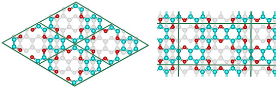
Figure 1.
The hexagonal unit cell (left) and the orthorhombic supercell (right) of bilayer graphocrown. The bottom layer coloured to white for clarity.
3. Results
3.1. Single Layer
Although the single-layer graphocrown (free-hanging graphocrown) is not the main focus of this work, we would like to start discussion from there. While phonon calculations demonstrate the stability of this material, according to work [69] it is not a sufficient criterion. Criticising artificial stabilisation with periodic boundary conditions, the authors of [69] rely on terminated flakes (where edge effects can, and quite often actually do, cause the distortion, as is discussed below). While for chemists the planarity of these fragments should be obvious, we followed the approaches of that work and the requirements of the “topology conservation theorem”, to demonstrate that periodic boundary conditions do not introduce any artificial stabilization of the unstable structure.
First of all, according to TCT, “the free-standing constituting fragments (unit cells) must perfectly fit planar low-dimensional space”. The dibenzodioxin unit is well known for being perfectly planar, and the minimal crown cycle (Figure 2a) that can be compiled from such dioxins keeps the perfect D6h point group (PBE/def2-TZVP, ORCA). Thus, there is no internal stress perpendicular to the plane to be compensated for.
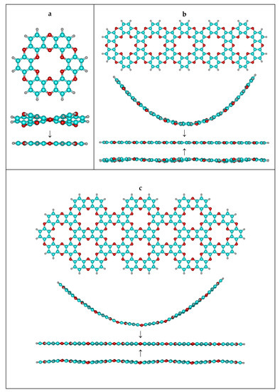
Figure 2.
Investigation of the stability of bent and wave clusters. (a) primitive unit – “single ring” (b) acene-like cluster (c) teropyrene-like cluster.
As the next step, we cut two different stripes from the single-layer graphocrown (in perpendicular directions), terminated them with hydrogens, and tried to bend them (Figure 2b,c). The relaxed scan in respect to the bending/torsional angle was performed in ORCA 5.0.4 with the r2SCAN-3c approach, which we consider as more reliable than the PM3 Hamiltonian intensively used in some work [69]. For consistency, we also cut graphene stripes of same shape. Figure 3 demonstrates the fact that graphocrown stripes can be bent (actually much more easily than graphene stripes), but still have minimal energy, being planar. In fact, due to hydrogen repulsion on the armchair edge, the graphene flakes actually have a destabilizing distortion. This also brings us to the controversy of the approach suggested in work [69]—while we agree that the improper usage of PBC might artificially stabilize nonoptimal conformations, the edge effects of an improperly terminated cluster approach might artificially destabilise planar structures, and the principal role here (for the single layers) is the lability or robustness of the “inner part” of the flake.
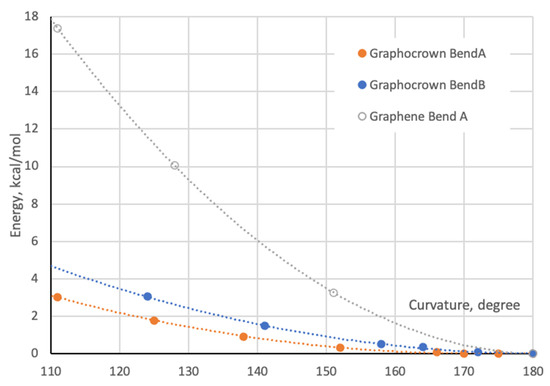
Figure 3.
Bending energy of graphocrown and graphene. BendA corresponds to the bending shown in Figure 2b, and BendB corresponds to the bending shown in Figure 2c. For the case of graphene we built a cluster based on structure 2b, all coordinates can be found in Supplementary Materials.
We also generated a number of differently distorted flakes, and performed their optimization. It is important to mention that for some “wave-style” geometries the optimization (smoothing of waves) goes through a very narrow PES, and very tight optimization criteria should be applied to reach the true minima (planar).
Next, following work [69] we performed a PM3 optimization of a large graphocrown flake (C528H52O238), which kept the flake planar as well as a 5 ns molecular dynamics simulation with a step of 0.5 fs with the NVT ensemble (details can be found in Supplementary Materials). Quite expectedly, the flake left the planarity (also increasing the total energy), and random concaves and convexities wandered over it (several snapshots can be found in Supplementary Materials). Under no condition should such behaviour be interpreted as material instability. The disruption of the pristine order is a natural feature of MD, and on “free-hanging” epitaxial graphene or boron nitride [70] similar waves or other fluctuating distortions were observed or simulated—the corresponding crystals are perfectly stable, as are the layers within them—and were perfectly planar.
Although the transformation between planar and nonplanar form could not be observed in PBC MD (as is specified in [69]), we built a waved single layer in PBC and performed its optimization in the cell that was able to change shape but keep the volume (ISYF = 4 in VASP). Once again, increase of numerical accuracy results in smoothening the waves.
3.2. Structure and Stability
Each layer of the pristine graphocrown is completely planar, almost independently of the stacking.
The investigated cell contains two layers of graphocrown, and thus several possible laying patterns were tested: “pore-to-pore”, “pore-to-ring” and “displaced” (Table 1). As one can see, “displaced” stacking is the most preferable, with quite a difference when compared to the alternatives. This means that layer shift is not a low-barrier process. The exfoliation energy of this material was found to be 2.78 eV per simulation cell (72 atoms) or 116 meV per C2O unit or 11.9 meV per Å2 (for a single layer). For comparison, the exfoliation energy calculated for the graphene supercell with two layers and the same number of atoms was 3.49 eV per cell, 48 meV per C atom or 18.4 meV per Å2 (for a single layer).

Table 1.
Comparison of the different stacking possibilities of graphocrown.
The reason for the unfavourable nature of the “pore-to-pore” stacking is the repulsive interaction of the oxygen lone pairs which face each other as the structure remains planar. This can be nicely demonstrated by non-covalent interaction (NCI) plots (Figure 4). While the “displaced” stacking on the interlayer distance of 6.5Å shows just the “unshaped” vdW interactions, the “pore-to-pore” demonstrates the very “well-defined” interaction regions, in particular for the interaction between the oxygens.
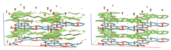
Figure 4.
NCI in “displaced” and “pore-to-pore” stackings of graphocrown. The red spindles in the centres of the 6-member rings correspond to known intramolecular repulsive interactions.
Next, we decided to evaluate the stability of our material. Therefore, we compared our graphocrown with the graphether of Liu [27] (which has the same generalized formula, C2O). It was found that graphocrown is significantly (over 1 eV per C2O unit) more stable than graphether. Keeping in mind the demonstrated stability of graphether and the lack of obvious pathways for the decomposition of graphocrown, we rely on the reasonable stability of the suggested system.
Furthermore, we compared the stability of graphocrown with respect to the simplest educt—hexahydroxybenzene (benzenehexol)—from which graphocrown could be obtained by straightforward polycondensation:
where C48O24 corresponds to the bulk graphocrown, while benzenehexol and water were calculated in the gas phase. The enthalpy of this reaction is 183 meV per C2O unit, and thus the reaction is endothermic. To the best of our knowledge, there are no detailed studies of products of the polycondensation of benzenehexol. On the other hand, a conductive two-dimensional MOF was experimentally obtained from hexahydroxybenzene and copper [71].
8 × C6(OH)6 = C48O24 + 24 × H2O
3.3. Electronic Structure
The band structure and DOS of graphocrown are presented in Figure 5. Please note that there are no discontinuities, but that the last three blocks correspond to edges that could not be included in the main sequence.
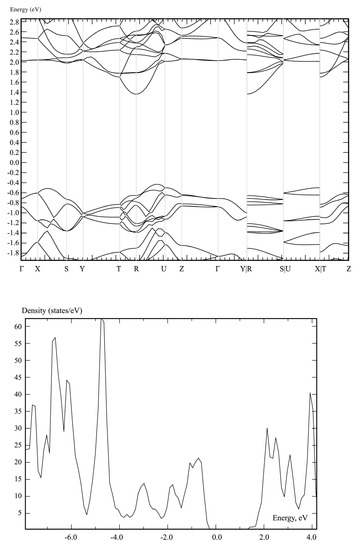
Figure 5.
The band structure and DOS of graphocrown calculated on a PBE level.
The PBE-predicted bandgap of graphocrown (1.79 eV) is larger than that of grapheter (0.81 eV), GaSe (1.63 eV) or MoS2 (1.75 eV), at the same level of theory [72].
For a more detailed insight into the near-band-edge states, the isosurfaces of the electron density of the valence band maximum (VBM) and conduction band minimum (CBM) are shown in Figure 6.
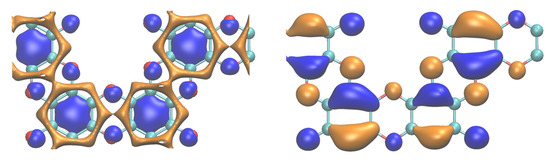
Figure 6.
CBM (left) and VBM (right) at the Γ point of graphocrown. The calculations were performed for the “displaced” bulk, but only one layer is shown, for clarity. Different colours correspond to different phases of the wavefunction; more details can be found in the Supplementary Materials. CBM and VBM calculated at point R are provided in the Supplementary Materials.
One can recognize continuous “channels” in the lowest conduction band, while the isosurface of the highest valence band is “well-isolated”. Obtained data indicate a higher electron than hole conductivity.
3.4. Carrier Mobility
The isosurfaces of the local ionisation potential (IEL) and local electron affinity (EAL) are shown in Figure 7.
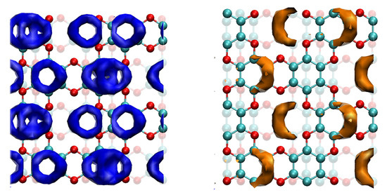
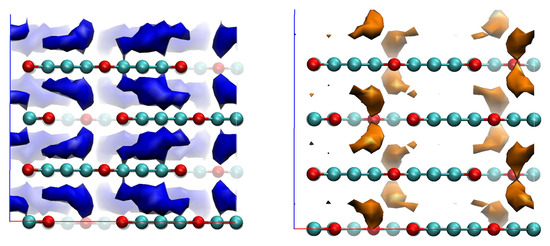
Figure 7.
EAL (blue) and IEL (orange) isosurfaces for bulk graphocrown. The strong cueing was applied to differentiate flakes in the front line. Isosurface cutoffs—20 and 390 kcal/mol, respectively.
In the case of the EAL of graphocrown, one can observe a kind of Moire pattern: the benzene rings that have no direct neighbours in layers above or below form “single rings”, while those with such neighbours form a more prominent “double ring, which provides a more efficient (and less coherent) conductive channel. For holes, on the other hand, we have an interesting feature: the most attractive sites seem to be not on atoms, but in between the oxygen rings.
No significant difference was observed between the results of the PM6 and AM1 calculations. The performed propagation simulations indicate that, perpendicular to the planes, the hole mobility is lower (by a factor of approximately 0.95) than the electron mobility.
3.5. Intercalation Complexes
“Normal” crowns, such as 18-Crown-6, coordinate the metal cation by rotating the carbon linkers so that the single oxygen pairs are directed toward it, making the complex planar. As was mentioned before, the oxygen’s lone pairs in the graphocrown are not pointing to the middle of the pore. Indeed, by placing the potassium cations at different positions along the pore of the pore–pore graphocrown stack, we found that in the 2D-layer plane there was not a minimum, but a transition, state, with one of the possible minima (such coordinated diffusion through the pore would have a barrier just above 1 eV). In fact, the deepest energy minimum for the potassium cations was unexpectedly found in the “pore-to-ring” structure.
While the binding energy of the potassium cation in 18-Crown-6 was found to be about 2.5 eV (dipole correction has to be applied, and the check-up calculations with nonperiodic software (ORCA [45,46], PBE/def2-TZVP) resulted in 2.41 eV), the binding in graphocrown is much stronger (about 4.65 eV per potassium cation in the “pore-to-ring” geometry with monopole correction), see Figure 8. These results are in a good agreement with the stronger binding 1.4 eV in the 18-crown-6 incorporated into the graphene, in comparison to the binding into the “normal” 18-Crown-6 [33].
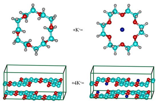
Figure 8.
Complexes of 18-Crown-6 and graphocrown with potassium cation.
One can expect that the coordination preference would depend on the size and charge of the cations. Thus, large metal atoms (which can also transform into polycations) are preferred for “pore-to-pore” coordination. Indeed, we observed that, for example, cerium cations strongly contract the layers of the graphocrown, forming almost covalent bonds. It is also possible to speculate about the prospects of using this material for the extraction of heavy-atom cations, and to screen the periodic table for patterns and the most notable cases, but we would like to omit this task and concentrate on another class of material.
Since graphocrown does not form complexes similar to “normal” crowns, and there is no place in a bulk structure for the counterions (and calculation of the polycationic bulk is complicated from a physical, and questionable from a chemical, point of view), we directed our focus to the intercalation compounds similar to KC8, where (initially neutral) metal atoms are located between the layers of the 2D-material.
We found out that in the neutral cell of C48O24K4, potassium occupies the space between the centers of the pores in the “pore-to-pore” configuration (Figure 9).
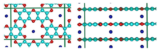
Figure 9.
Top and side view of the K-graphocrown intercalation complex.
The Bader charge [53] analysis shows that in this system potassium atoms lose over 90% of their valence electron to the oxocarbon layers (similar to KC8). While Bader charges (as well as many other charges) are often controversial, we also performed a cluster simulation with a sandwich of a potassium atom between two “single rings” (shown in Figure 2a). We would like to mention the fact that ionisation calculated in this way should likely be overestimated, in comparison to the PBC bulk. For this system on PBE/def2-TZVP we obtained a Mulliken charge on K—+0.71, and a Löwdin charge of +0.18. (See charge distribution in Supplementary Materials). Such a difference should not be confusing, as pure agreement between different charge models is well known [73]. One can also try to make some evaluation relative to other materials, i.e., comparing the results with LiF (controversial, yet sometimes used as example, as Li is definitely a worse electron donor than K, and there are also stronger acceptors than F). From such a comparison, one can see that the K in the K-graphocrown is 10 to 20% (Bader and Mulliken, respectively), less ionic than the Li in LiF. As thousands of different references can be suggested here, and as the results still remain speculative and controversial, no further comparisons were performed here.
A critical point search (QTAIM analysis) showed for each potassium atom twelve bond points between it and the surrounding oxygens (a positive Laplacian and “field value” of 0.006, which should correspond to an extremely weak hydrogen bond), and two bond points towards the surrounding potassium atoms (a “field value” of 0.003), Figure 10. Typical “field values” for C-C bonds in the system are about 0.2–0.3.
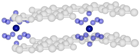
Figure 10.
Critical bond points (QTAIM) in potassium intercalated graphocrown.
Finally, we performed a comparison of K-graphite (KC8) and our K-graphocrown-intercalate in terms of their relative stability. For this purpose, we have constructed the following equation:
K-graphite + graphocrown ↔ graphite + K-graphocrown
All cell energies were scaled by one potassium atom (i.e., a K-graphite cell includes eight potassium atoms). Surprisingly, this migration (from KC8 to K-graphocrown) appears to be energetically favorable (0.6 eV per each K-atom). While KC8 is quite stable under certain conditions (being, however, a very active reducing agent), we assume that K-graphocrown (and other metal-intercalates) could be the observable compounds.
An interesting point is the question of the existence of a charge-carrier transfer channel through the metal atoms of the structure—an electrical wire 1 atom thick.
Contrary to the consistent results for pristine graphocrown, in the case of the potassium intercalate, the PM6 and AM1 Hamiltonians showed different results for EAL (Figure 11).
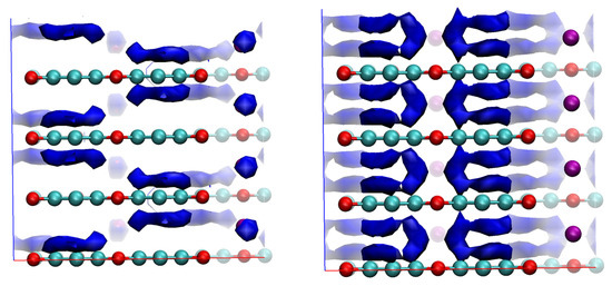
Figure 11.
EAL with PM6 and AM1 Hamiltonians. Visualisation cutoffs: for PM6—45 kcal/mol, for AM1—30 kcal/mol.
While AM1 shows no energy minima on the potassium atoms, and thus no electron conduction channel through them, PM6 demonstrates a “coherent channel” going through this metal rod.
To the best of our knowledge, this is the first example where a change in the Hamiltonian has had a qualitative effect on EAL or IEL.
As a final remark regarding intercalation systems, we would like to mention the fact that such systems typically have a high number of low frequencies (especially for intercalated atoms), and to speculate on a significant role for anharmonicity. Since there is no convenient black-box method for accurate evaluation of anharmonicity, we prefer to refrain from making any ill-defined speculation on the entropy-related part.
3.6. Related Materials
Before coming to the end of this manuscript on the graphocrown crystal, we would like to spend a few more paragraphs on a discussion of other materials with similar or related structures.
The possibility of bending the graphocrown similarly to graphene opens the way to graphocrown nanotubes (Figure 12a). The formal polycondensation reaction of 1,3,5-triformylbenzene should end with a graphocrown analogue with oxygen atoms shifted to the methylene (CH2) groups—a framework hydrocarbon with a primitive unit (>C-CH2-)n (Figure 12b). Further oxidation (dehydrogenation) of this structure could result in a graphocrown analogue with CH groups at the graphocrown site (Figure 12c). This structure could also be classified as a hydrogen-terminated extremely porous graphene. An interesting feature of this structure is that, although the structure can be nicely split into independent 18-membered aromatic rings that go around the pores, a similar attempt to split into Clar’s sextets (of benzene rings) would end up in a polyradical system. Apart from graphether and graphene epoxide, one more C2O polymorph is possible, at least theoretically: polyether of polyene-polyol (Figure 12d). Although this material has an extremely simple primitive cell and fully replicates graphocrown in types of bonds (each oxygen connected with two sp2 carbons, each carbon connected with one oxygen and two of the same carbons), we have significant doubts about the stability of such a material. One can also try to build some other 2D carbon oxide structures with pores of a similar or larger size, for example using “carbon-rich” per-hydroxy-naphthalene and “oxygen-rich” “tetrahydroxy-ethylene” units (Figure 12e–h). We would like to underline the fact that we are not stating the planarity of any of the structures (12b–h), neither in terms of their stability or of any other property. In Supplementary Materials we provide the PBE-optimised (VASP) geometry of the 12 × 12 nanotube and polyene-polyol, as it might take some time for the engaged reader to build these structures. The remaining structures can be easily constructed from the graphene layer.
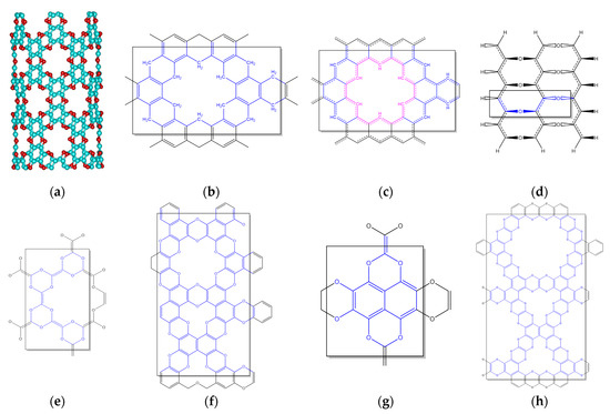
Figure 12.
C2O polymorphs and derivatives. (a) 12 × 12 nanotube, (b) 1,3,5-triformylbenzene polycondensate, (c) porous graphene, (d) polyether of polyene-polyol, (e–h) different polycondensates of “tetrahydroxy-ethylene” with benzenehexol and perhydroxy-naphtalene.
4. Conclusions
In this work we designed a new 2D-material—graphocrown—and studied its properties in comparison to known or previously proposed materials. Graphocrown was found to be more stable than graphether, despite the fact that its formation from benzenehexol was assumed to be an endothermic process. We found that the most favourable (displaced) stacking of monolayers was in the bulk material, and explained it through the non-covalent interactions. It was demonstrated that graphocrown binds potassium cations much more strongly than 18-crown-6 itself, and even more strongly than “crown-in-graphene”. Furthermore, we showed that, similarly to graphene, graphocrown can form intercalation compounds with potassium (and potentially many other alkaline and non-alkaline metals), forming one-dimensional metal rods in the pores. In this process (according to the QTAIM approach), potassium atoms predominantly lose their electrons. The band structure as well as the charge-carrier mobility of graphocrown were studied. We hope that the results of this study will stimulate the development of a next generation of promising materials.
Supplementary Materials
The following supporting information can be downloaded at https://www.mdpi.com/article/10.3390/cryst13060909/s1. Additional details of performed calculations and postprocessing as well as coordinates of discussed systems can be found in Supplementary Materials.
Author Contributions
The research was conceptualized and proposed by D.I.S.; the methodology was discussed by D.I.S., M.K., M.A.K. and A.S.O.; DFT calculations were performed by D.I.S. and M.A.K.; calculations of charge-carrier mobilities were performed by M.K.; single-and multi-reference simulations were performed by D.I.S.; the supervision and project administration was by A.S.O. and D.I.S.; results were visualized by D.I.S. and M.K.; the original draft was written by D.I.S. and A.S.O.; review and editing were carried out by D.I.S., M.A.K. and A.S.O. All authors have read and agreed to the published version of the manuscript.
Funding
This research received no external funding.
Informed Consent Statement
Not applicable.
Data Availability Statement
Not applicable.
Acknowledgments
D.I.S acknowledge the support of Baden-Württemberg through bwHPC (bwUniCluster) and the German Research Foundation (DFG) through grant no INST 40/575-1 FUGG (JUSTUS 2 cluster).
Conflicts of Interest
The authors declare no conflict of interest.
References
- Ares, P.; Novoselov, K.S. Recent Advances in Graphene and Other 2D Materials. Nano Mater. Sci. 2022, 4, 3–9. [Google Scholar] [CrossRef]
- Wallace, P.R. The Band Theory of Graphite. Phys. Rev. 1947, 71, 622–634. [Google Scholar] [CrossRef]
- Balandin, A.A.; Ghosh, S.; Bao, W.; Calizo, I.; Teweldebrhan, D.; Miao, F.; Lau, C.N. Superior Thermal Conductivity of Single-Layer Graphene. Nano Lett. 2008, 8, 902–907. [Google Scholar] [CrossRef] [PubMed]
- Blase, X.; Benedict, L.X.; Shirley, E.L.; Louie, S.G. Hybridization Effects and Metallicity in Small Radius Carbon Nanotubes. Phys. Rev. Lett. 1994, 72, 1878–1881. [Google Scholar] [CrossRef]
- Zhang, Y.; Tang, T.-T.; Girit, C.; Hao, Z.; Martin, M.C.; Zettl, A.; Crommie, M.F.; Shen, Y.R.; Wang, F. Direct Observation of a Widely Tunable Bandgap in Bilayer Graphene. Nature 2009, 459, 820–823. [Google Scholar] [CrossRef]
- Blake, P.; Brimicombe, P.D.; Nair, R.R.; Booth, T.J.; Jiang, D.; Schedin, F.; Ponomarenko, L.A.; Morozov, S.V.; Gleeson, H.F.; Hill, E.W.; et al. Graphene-Based Liquid Crystal Device. Nano Lett. 2008, 8, 1704–1708. [Google Scholar] [CrossRef]
- Urade, A.R.; Lahiri, I.; Suresh, K.S. Graphene Properties, Synthesis and Applications: A Review. JOM 2023, 75, 614–630. [Google Scholar] [CrossRef]
- Taheri, B.; Yaghoobi Nia, N.; Agresti, A.; Pescetelli, S.; Ciceroni, C.; Del Rio Castillo, A.E.; Cinà, L.; Bellani, S.; Bonaccorso, F.; Di Carlo, A. Graphene-Engineered Automated Sprayed Mesoscopic Structure for Perovskite Device Scaling-Up. 2D Mater. 2018, 5, 045034. [Google Scholar] [CrossRef]
- Iqbal, M.A.; Anwar, N.; Malik, M.; Al-Bahrani, M.; Islam, M.R.; Choi, J.R.; Pham, P.V.; Liu, X. Nanostructures/Graphene/Silicon Junction-Based High-Performance Photodetection Systems: Progress, Challenges, and Future Trends. Adv. Mater. Interfaces 2023, 10, 2202208. [Google Scholar] [CrossRef]
- Fu, P.; Teri, G.-L.; Chao, X.-L.; Li, J.; Li, Y.-H.; Yang, H. Modified Graphene-FEVE Composite Coatings: Application in the Repair of Ancient Architectural Color Paintings. Coatings 2020, 10, 1162. [Google Scholar] [CrossRef]
- Pang, J.; Peng, S.; Hou, C.; Zhao, H.; Fan, Y.; Ye, C.; Zhang, N.; Wang, T.; Cao, Y.; Zhou, W.; et al. Applications of Graphene in Five Senses, Nervous System, and Artificial Muscles. ACS Sensors 2023, 8, 482–514. [Google Scholar] [CrossRef]
- Ghamkhari, A.; Abbaspour-Ravasjani, S.; Talebi, M.; Hamishehkar, H.; Hamblin, M.R. Development of a Graphene Oxide-Poly Lactide Nanocomposite as a Smart Drug Delivery System. Int. J. Biol. Macromol. 2021, 169, 521–531. [Google Scholar] [CrossRef] [PubMed]
- Nasker, S.S.; Ajayan, P.M.; Nayak, S. Emerging Trends and Future Direction of Graphene Family of Materials as Potential Antimicrobials: A Critical Review. ACS Mater. Lett. 2023, 5, 673–693. [Google Scholar] [CrossRef]
- Li, X.; Wang, X.; Zhang, L.; Lee, S.; Dai, H. Chemically Derived, Ultrasmooth Graphene Nanoribbon Semiconductors. Science 2008, 319, 1229–1232. [Google Scholar] [CrossRef]
- Zhao, W.; Papp, C.; Steinrück, H.-P. Heterographenes. In Encyclopedia of Polymeric Nanomaterials; Springer: Berlin/Heidelberg, Germany, 2014; pp. 1–15. [Google Scholar]
- Thomas, A.; Fischer, A.; Goettmann, F.; Antonietti, M.; Müller, J.-O.; Schlögl, R.; Carlsson, J.M. Graphitic Carbon Nitride Materials: Variation of Structure and Morphology and Their Use as Metal-Free Catalysts. J. Mater. Chem. 2008, 18, 4893. [Google Scholar] [CrossRef]
- Tian, X.; Xuan, X.; Yu, M.; Mu, Y.; Lu, H.-G.; Zhang, Z.; Li, S.-D. Predicting Two-Dimensional Semiconducting Boron Carbides. Nanoscale 2019, 11, 11099–11106. [Google Scholar] [CrossRef]
- Watanabe, K.; Taniguchi, T.; Kanda, H. Direct-Bandgap Properties and Evidence for Ultraviolet Lasing of Hexagonal Boron Nitride Single Crystal. Nat. Mater. 2004, 3, 404–409. [Google Scholar] [CrossRef]
- Compton, O.C.; Nguyen, S.T. Graphene Oxide, Highly Reduced Graphene Oxide, and Graphene: Versatile Building Blocks for Carbon-Based Materials. Small 2010, 6, 711–723. [Google Scholar] [CrossRef]
- Kim, F.; Cote, L.J.; Huang, J. Graphene Oxide: Surface Activity and Two-Dimensional Assembly. Adv. Mater. 2010, 22, 1954–1958. [Google Scholar] [CrossRef]
- Gutiérrez-Cruz, A.; Ruiz-Hernández, A.R.; Vega-Clemente, J.F.; Luna-Gazcón, D.G.; Campos-Delgado, J. A Review of Top-down and Bottom-up Synthesis Methods for the Production of Graphene, Graphene Oxide and Reduced Graphene Oxide. J. Mater. Sci. 2022, 57, 14543–14578. [Google Scholar] [CrossRef]
- Bharatiya, D.; Parhi, B.; Sahu, H.; Swain, S.K. Factors Influencing the Dielectric Properties of GO/MO Nanocomposites: Review. J. Mater. Sci. Mater. Electron. 2023, 34, 452. [Google Scholar] [CrossRef]
- Cai, Y.; Pan, Y.; Liu, L.; Zhang, T.; Liang, C.; Mou, X.; Ye, X.; Wang, W.; Dong, X. Succinct Croconic Acid-Based near-Infrared Functional Materials for Biomedical Applications. Coord. Chem. Rev. 2023, 474, 214865. [Google Scholar] [CrossRef]
- Zhang, Z.; Ma, J.; Zhang, R.; Rajagopalan, R.; Tang, Y.; Ren, Y.; Wang, H. Oxocarbons Electrode Materials for Alkali Ion Batteries: Challenges, Strategies and Development. Batter. Supercaps 2021, 4, 1791–1802. [Google Scholar] [CrossRef]
- Colmenero, F. Anomalous Mechanical Behavior of the Deltic, Squaric and Croconic Cyclic Oxocarbon Acids. Mater. Res. Express 2019, 6, 045610. [Google Scholar] [CrossRef]
- Liu, L.; Cheng, B.; Yang, Z.; Wang, H.; Yue, C.; Hu, F. Oxocarbon Organic Conjugated Compounds for Lithium-Ion Batteries and Solar Cells: Progress and Perspectives. Curr. Org. Chem. 2020, 24, 200–215. [Google Scholar] [CrossRef]
- Zhu, G.-L.; Ye, X.-J.; Liu, C.-S. Graphether: A Two-Dimensional Oxocarbon as a Direct Wide-Band-Gap Semiconductor with High Mechanical and Electrical Performances. Nanoscale 2019, 11, 22482–22492. [Google Scholar] [CrossRef] [PubMed]
- Yang, X.; Han, D.; Fan, H.; Wang, M.; Du, M.; Wang, X. First-Principles Calculations of Phonon Behaviors in Graphether: A Comparative Study with Graphene. Phys. Chem. Chem. Phys. 2021, 23, 123–130. [Google Scholar] [CrossRef]
- Jiang, Y.; Guo, Y.; Zeng, H.; Lin, L.; Yan, X. Symmetry-Dependent Electronic Structure Transition in Graphether Nanoribbons. AIP Adv. 2022, 12, 015118. [Google Scholar] [CrossRef]
- Liu, Z.; Nalluri, S.K.M.; Stoddart, J.F. Surveying Macrocyclic Chemistry: From Flexible Crown Ethers to Rigid Cyclophanes. Chem. Soc. Rev. 2017, 46, 2459–2478. [Google Scholar] [CrossRef]
- Oshchepkov, A.; Oshchepkov, M.; Arkhipova, A.; Panchenko, P.; Fedorova, O. Synthesis of 4-Nitro-N-Phenyl-1,8-Naphthalimide Annulated to Thia- and Azacrown Ether Moieties. Synthesis 2017, 49, 2231–2240. [Google Scholar] [CrossRef]
- Fang, A.; Kroenlein, K.; Riccardi, D.; Smolyanitsky, A. Highly Mechanosensitive Ion Channels from Graphene-Embedded Crown Ethers. Nat. Mater. 2019, 18, 76–81. [Google Scholar] [CrossRef]
- Guo, J.; Lee, J.; Contescu, C.I.; Gallego, N.C.; Pantelides, S.T.; Pennycook, S.J.; Moyer, B.A.; Chisholm, M.F. Crown Ethers in Graphene. Nat. Commun. 2014, 5, 5389. [Google Scholar] [CrossRef]
- Pandey, R.P.; Kallem, P.; Hegab, H.M.; Rasheed, P.A.; Banat, F.; Hasan, S.W. Cross-Linked Laminar Graphene Oxide Membranes for Wastewater Treatment and Desalination: A Review. J. Environ. Manag. 2022, 317, 115367. [Google Scholar] [CrossRef]
- Egorova, B.V.; Oshchepkov, M.S.; Fedorov, Y.V.; Fedorova, O.A.; Budylin, G.S.; Shirshin, E.A.; Kalmykov, S.N. Complexation of Bi3+, Ac3+, Y3+, Lu3+, La3+ and Eu3+ with Benzo-Diaza-Crown Ether with Carboxylic Pendant Arms. Radiochim. Acta 2016, 104, 555–565. [Google Scholar] [CrossRef]
- Pemberton, B.C.; Raghunathan, R.; Volla, S.; Sivaguru, J. From Containers to Catalysts: Supramolecular Catalysis within Cucurbiturils. Chem. A Eur. J. 2012, 18, 12178–12190. [Google Scholar] [CrossRef] [PubMed]
- An, Y.-C.; Gao, X.-X.; Jiang, W.-L.; Han, J.-L.; Ye, Y.; Chen, T.-M.; Ren, R.-Y.; Zhang, J.-H.; Liang, B.; Li, Z.-L.; et al. A Critical Review on Graphene Oxide Membrane for Industrial Wastewater Treatment. Environ. Res. 2023, 223, 115409. [Google Scholar] [CrossRef] [PubMed]
- Lim, J.S.; Kim, G. First-Principles Modeling of Water Permeation through Periodically Porous Graphene Derivatives. J. Colloid Interface Sci. 2019, 538, 367–376. [Google Scholar] [CrossRef]
- Liu, T.; Ding, J.; Su, Z.; Wei, G. Porous Two-Dimensional Materials for Energy Applications: Innovations and Challenges. Mater. Today Energy 2017, 6, 79–95. [Google Scholar] [CrossRef]
- Gracia, J.; Kroll, P. Corrugated Layered Heptazine-Based Carbon Nitride: The Lowest Energy Modifications of C3N4 Ground State. J. Mater. Chem. 2009, 19, 3013. [Google Scholar] [CrossRef]
- Perdew, J.P.; Burke, K.; Ernzerhof, M. Generalized Gradient Approximation Made Simple. Phys. Rev. Lett. 1996, 77, 3865–3868. [Google Scholar] [CrossRef]
- Kresse, G.; Furthmüller, J. Efficiency of Ab-Initio Total Energy Calculations for Metals and Semiconductors Using a Plane-Wave Basis Set. Comput. Mater. Sci. 1996, 6, 15–50. [Google Scholar] [CrossRef]
- Kresse, G.; Furthmüller, J. Efficient Iterative Schemes for Ab Initio Total-Energy Calculations Using a Plane-Wave Basis Set. Phys. Rev. B 1996, 54, 11169–11186. [Google Scholar] [CrossRef] [PubMed]
- Grimme, S.; Antony, J.; Ehrlich, S.; Krieg, H. A Consistent and Accurate Ab Initio Parametrization of Density Functional Dispersion Correction (DFT-D) for the 94 Elements H-Pu. J. Chem. Phys. 2010, 132, 154104. [Google Scholar] [CrossRef]
- Neese, F. The ORCA Program System. WIREs Comput. Mol. Sci. 2012, 2, 73–78. [Google Scholar] [CrossRef]
- Neese, F. Software Update: The ORCA Program System, Version 4.0. WIREs Comput. Mol. Sci. 2018, 8, e1327. [Google Scholar] [CrossRef]
- Grimme, S.; Hansen, A.; Ehlert, S.; Mewes, J.-M. R 2 SCAN-3c: A “Swiss Army Knife” Composite Electronic-Structure Method. J. Chem. Phys. 2021, 154, 064103. [Google Scholar] [CrossRef]
- Hennemann, M.; Clark, T. EMPIRE: A Highly Parallel Semiempirical Molecular Orbital Program: 1: Self-Consistent Field Calculations. J. Mol. Model. 2014, 20, 2331. [Google Scholar] [CrossRef]
- Margraf, J.T.; Hennemann, M.; Meyer, B.; Clark, T. EMPIRE: A Highly Parallel Semiempirical Molecular Orbital Program: 2: Periodic Boundary Conditions. J. Mol. Model. 2015, 21, 144. [Google Scholar] [CrossRef]
- Stewart, J.J.P. Optimization of Parameters for Semiempirical Methods IV: Extension of MNDO, AM1, and PM3 to More Main Group Elements. J. Mol. Model. 2004, 10, 155–164. [Google Scholar] [CrossRef]
- Tang, W.; Sanville, E.; Henkelman, G. A Grid-Based Bader Analysis Algorithm without Lattice Bias. J. Phys. Condens. Matter 2009, 21, 084204. [Google Scholar] [CrossRef]
- Sanville, E.; Kenny, S.D.; Smith, R.; Henkelman, G. Improved Grid-Based Algorithm for Bader Charge Allocation. J. Comput. Chem. 2007, 28, 899–908. [Google Scholar] [CrossRef] [PubMed]
- Henkelman, G.; Arnaldsson, A.; Jónsson, H. A Fast and Robust Algorithm for Bader Decomposition of Charge Density. Comput. Mater. Sci. 2006, 36, 354–360. [Google Scholar] [CrossRef]
- Otero-de-la-Roza, A.; Blanco, M.A.; Pendás, A.M.; Luaña, V. Critic: A New Program for the Topological Analysis of Solid-State Electron Densities. Comput. Phys. Commun. 2009, 180, 157–166. [Google Scholar] [CrossRef]
- Otero-de-la-Roza, A.; Johnson, E.R.; Luaña, V. Critic2: A Program for Real-Space Analysis of Quantum Chemical Interactions in Solids. Comput. Phys. Commun. 2014, 185, 1007–1018. [Google Scholar] [CrossRef]
- Maintz, S.; Deringer, V.L.; Tchougréeff, A.L.; Dronskowski, R. LOBSTER: A Tool to Extract Chemical Bonding from Plane-Wave Based DFT. J. Comput. Chem. 2016, 37, 1030–1035. [Google Scholar] [CrossRef]
- Nelson, R.; Ertural, C.; George, J.; Deringer, V.L.; Hautier, G.; Dronskowski, R. LOBSTER: Local Orbital Projections, Atomic Charges, and Chemical-bonding Analysis from Projector-augmented-wave-based Density-functional Theory. J. Comput. Chem. 2020, 41, 1931–1940. [Google Scholar] [CrossRef]
- Humphrey, W.; Dalke, A.; Schulten, K. VMD: Visual Molecular Dynamics. J. Mol. Graph. 1996, 14, 33–38. [Google Scholar] [CrossRef]
- Akhmetov, V.; Feofanov, M.; Sharapa, D.I.; Amsharov, K. Alumina-Mediated π-Activation of Alkynes. J. Am. Chem. Soc. 2021, 143, 15420–15426. [Google Scholar] [CrossRef]
- Chemcraft-Graphical Software for Visualization of Quantum Chemistry Computations. Available online: https://www.chemcraftprog.com (accessed on 30 May 2023).
- Sjoberg, P.; Murray, J.S.; Brinck, T.; Politzer, P.A. Average Local Ionization Energies on the Molecular Surfaces of Aromatic Systems as Guides to Chemical Reactivity. Can. J. Chem. 1990, 68, 1440–1443. [Google Scholar] [CrossRef]
- Ehresmann, B.; Martin, B.; Horn, A.H.C.; Clark, T. Local Molecular Properties and Their Use in Predicting Reactivity. J. Mol. Model. 2003, 9, 342–347. [Google Scholar] [CrossRef] [PubMed]
- Clark, T. The Local Electron Affinity for Non-Minimal Basis Sets. J. Mol. Model. 2010, 16, 1231–1238. [Google Scholar] [CrossRef]
- Hennemann, M. EH5cube. 2019. Available online: https://www.ceposinsilico.de/products/empire.htm (accessed on 30 May 2023).
- Dewar, M.J.S.; Zoebisch, E.G.; Healy, E.F.; Stewart, J.J.P. Development and Use of Quantum Mechanical Molecular Models. 76. AM1: A New General Purpose Quantum Mechanical Molecular Model. J. Am. Chem. Soc. 1985, 107, 3902–3909. [Google Scholar] [CrossRef]
- Stewart, J.J.P. Optimization of Parameters for Semiempirical Methods V: Modification of NDDO Approximations and Application to 70 Elements. J. Mol. Model. 2007, 13, 1173–1213. [Google Scholar] [CrossRef] [PubMed]
- Kriebel, M.; Sharapa, D.; Clark, T. Charge Transport in Organic Materials: Norm-Conserving Imaginary Time Propagation with Local Ionization Energy as the External Potential. J. Chem. Theory Comput. 2017, 13, 6308–6316. [Google Scholar] [CrossRef] [PubMed]
- Kriebel, M.; Hennemann, M.; Beierlein, F.R.; Medina, D.D.; Bein, T.; Clark, T. Propagation of Holes and Electrons in Metal–Organic Frameworks. J. Chem. Inf. Model. 2019, 59, 5057–5064. [Google Scholar] [CrossRef] [PubMed]
- Avramov, P.V.; Kuklin, A.V. Topological and Quantum Stability of Low-Dimensional Crystalline Lattices with Multiple Nonequivalent Sublattices. New J. Phys. 2022, 24, 103015. [Google Scholar] [CrossRef]
- Talla, J.A.; Almahmoud, E.A.; Abu-Farsakh, H. Rippling Effect on the Electrical Properties of Boron Nitride Monolayer: Density Functional Theory. Semiconductors 2021, 55, 696–703. [Google Scholar] [CrossRef]
- Park, J.; Hinckley, A.C.; Huang, Z.; Feng, D.; Yakovenko, A.A.; Lee, M.; Chen, S.; Zou, X.; Bao, Z. Synthetic Routes for a 2D Semiconductive Copper Hexahydroxybenzene Metal–Organic Framework. J. Am. Chem. Soc. 2018, 140, 14533–14537. [Google Scholar] [CrossRef]
- Zhou, J.; Shen, L.; Costa, M.D.; Persson, K.A.; Ong, S.P.; Huck, P.; Lu, Y.; Ma, X.; Chen, Y.; Tang, H.; et al. 2DMatPedia, an Open Computational Database of Two-Dimensional Materials from Top-down and Bottom-up Approaches. Sci. Data 2019, 6, 86. [Google Scholar] [CrossRef]
- Frank, J. Introduction to Computational Chemistry, 2nd ed.; John Wiley & Sons Ltd.: Hoboken, NJ, USA, 2007. [Google Scholar]


Disclaimer/Publisher’s Note: The statements, opinions and data contained in all publications are solely those of the individual author(s) and contributor(s) and not of MDPI and/or the editor(s). MDPI and/or the editor(s) disclaim responsibility for any injury to people or property resulting from any ideas, methods, instructions or products referred to in the content. |
© 2023 by the authors. Licensee MDPI, Basel, Switzerland. This article is an open access article distributed under the terms and conditions of the Creative Commons Attribution (CC BY) license (https://creativecommons.org/licenses/by/4.0/).