Abstract
Orientations, roughnesses, and cavities of crystals are typical factors influencing the servicing reliability of metals in corrosive environments. A phase-field scheme for modeling stress-corrosion coupled damage (SCCD) is developed. The effects of the crystal factors on SCCD are numerically simulated using the incremental-iterative scheme of the user-defined finite elements. The impacts of orientations, roughnesses, and cavities on the corrosion rate of magnesium (Mg) in corrosive environments are discussed quantitatively. It is found that crystal textures and surface roughnesses can significantly influence the diffusion-controlled corrosion rate. Strong basal texture and a smooth surface of the crystal can significantly enhance the corrosion resistance of Mg. The cavity, as a typical crystal defect, is capable of inducing the damage path and modulating the corrosion rate. The design of crystal-scale features, such as orientations, roughnesses, and cavities, is promising for the enhancement of the resistance to SCCD.
1. Introduction
Corrosion is a ubiquitous and highly destructive issue for most metal equipment [1], especially for Mg with its very low free corrosion potential. Among the various corrosion failures, stress-corrosion coupled damage (SCCD) is a kind of progressive damage caused by elastoplastic deformation accumulation and an electrochemical environment, which can significantly reduce the service performance of metals in corrosive environments. SCCD severely limits the reliability of critical industrial equipment [2].
The traditional methods to enhance the corrosion resistance are mainly coating technology [3,4,5] and the alloying trial-and-error method [4,6]. However, under the coupling effect of a corrosive environment and severe mechanical loading, the coating and the interfaces between the second phases and the Mg matrix are easily damaged, and the formed micropores and cracks can accelerate the local damage. Recently, it was found that the crystal structure in the metals has a significant effect on corrosion resistance. Song et al. [7] and Sabbaghian et al. [8] experimentally found that the polycrystalline orientation of AZ31 Mg alloy significantly affected the corrosion rate. Gill et al. [9] found that surface roughness had a significant effect on corrosion and polished samples showed low corrosion rates for Mg-4Zn alloy. However, the physical mechanisms of orientations and roughnesses influencing corrosion rate have been unclear. Moreover, Li et al. [10] found that Tellurium (Te) segregation led to the nanocavities at the grain boundaries, which further evolved into intergranular cracks and accelerated the corrosion rate. Whereas the details that the cavity influences the corrosion path and corrosion rate were not given.
In addition, some scholars have conducted numerical studies on the effect of crystal structure on corrosion rate. Ansari et al. [11] and Mai et al. [12] used the phase-field method to simulate the inhibition effect of different crystal orientations on corrosion; Mai et al. [12] and Gao et al. [13] used the phase-field method to simulate the process of electrochemical polishing; Hu et al. [14] used a continuum residual multiaxial ductility damage mechanics model to simulate the formation of cracks at the cavities and accelerate their propagation. However, these studies were not performed on Mg with hexagonal close-packed (HCP) crystal structures. The weak symmetry of HCP crystal structures could induce the orientation-dependent defects and anisotropy of deformation and damage, leading to significant differences in corrosion rate and paths. In addition, the formation and destruction of the passive film (mainly Mg(OH)2), which can periodically decrease and increase corrosion currently density, need to be considered while the Mg structures are undergoing mechanical deformations and simultaneously servicing in the corrosive environment. Therefore, the quantitative studies on the effects of orientations, roughnesses, and cavities on stress-corrosion coupled damage in Mg, which can model crystal features, capture defects and damage evolution, and are different from time-consuming experiments, are necessary for the crystal design for the resistance to SCCD.
Some theoretical and numerical frameworks of stress corrosion cracking have been proposed. Cui et al. [15] developed a new theoretical and numerical framework for multi-field coupling issues, such as mechanical deformation-anodic degradation-passive behavior-ion transport in the process of stress corrosion cracking, and the mechanical deformation system and the electrochemical system were separated. Furthermore, a time-period passivation model was established based on the phenomenological fitting. The conclusions showed that the degradation was driven by chemical potential, and the rupture process of the passive film was caused only by plastic deformation stress. Lin et al. [16] thought that the degradation of the pre-stressed metal phase was only related to corrosion. The effect of the mechanical potential on damage was ignored in the established theoretical and numerical framework. Nguyen et al. [17] developed a theoretical and numerical framework that simulated stress corrosion cracking, and the mechanical system and the electrochemical system were also independent in this framework, in which the damage was driven only by the mechanical potential, and the ion diffusion was coupled with brittle damage by affecting fracture toughness. However, Lin and Ruan [18] indicated that the damage rate was jointly controlled by the mechanical load and corrosion reaction rate. Nguyen et al. [19] thought that the damage/degradation process was jointly driven by the mechanical and chemical potentials. Currently, there is a strong controversy concerning the driving force of the damage/degradation process. In the authors’ opinion, for the structures undergoing severe mechanical deformations and simultaneously servicing in a strong corrosive environment, the assumption that mechanical and chemical potentials cooperatively drive the irreversible damage/degradation process is more reasonable.
Based on the above discussion, in this study, the corrosion/damage evolution process is assumed to be directly driven by the cooperation of mechanical energy and chemical potential. The purposes of this study are to develop a multi-physical framework for the SCCD and to provide guidance for the crystal structure design for the resistance enhancement of Mg.
2. Materials and Methods
In the current study, the materials used in the simulation are polycrystalline pure Mg or Mg alloys without considering the alloying effect. If alloys contain precipitates, it is necessary to introduce the micro-galvanic corrosion and the elastic-plastic mismatch into the framework.
The corrosion solution used in the simulation is pure water. In the process of the prestressed Mg reacting with water, the anodic degradation, the deposition of the passive film (mainly Mg(OH)2), and the damage of the passive film led by stresses need to be considered. If other corrosive solutions are used, such as 5 wt.% NaCl, 40 wt.% hydrofluoric acids, and so on, it is necessary to further consider various cathodic reactions (Cl−, OH−) and the mass transfer of the cathodic ions.
The details of the multi-physics coupling systems are presented in Figure 1, where Equations (1)–(3) are the generalized equilibrium equations of the deformation field, damage field, and concentration field, respectively. In this coupling system, for the Mg structure undergoing the severe mechanical deformations and simultaneously servicing in a strong corrosive environment, the corrosion/damage evolution process is assumed to be driven by the cooperation of mechanical energy and chemical potential, which is different from work [15]; the degradation of the mechanical stiffness is inevitably caused by the corrosion/damage of metals, and the ion transportation is dominated by the concentration-gradient-controlled diffusion. Referring to the works [11,15], the constitutive relationships of the multi-physics coupling behaviors can be built.
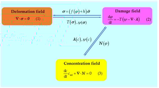
Figure 1.
Schematic of multi-physical field coupling.
Taking into account the degradation and using for the undamaged configuration, the mechanical force balance (1) is given as follows:
where represents the degradation function, which can appropriately describe the stiffness degradation. , varying from 1 to 0, represents the phase-field order parameter (1 represents being intact, 0 represents being completely damaged), is adopted throughout this work to ensure convergence, and represents the stress tensor for the undamaged configuration. The negative damage driving force is the gradient of free energy with respect to . When , the first-order derivative of the degradation function from work [15] equals zero, which leads to the disappearance of the negative damage driving force. Therefore, the degradation function has been proposed.
For the chemomechanical damage caused by both severe mechanical deformations and a strong corrosive environment, the negative damage driving force , which can drive the corrosion/damage process, is given by:
where is a parameter related to the critical energy for damage, represents the surface energy density, represents the interfacial thickness, and are the elastic and plastic components of the mechanical free energy density for the intact configuration, represents the fourth-order elastic tensor, represents the elastic part of the strain tensor, represents the plastic strain tensor, represents a free energy density curvature, represents the dimensionless concentration, represents the height of the double-well potential, and . To satisfy the electrochemical requirements, . represents the normalized equilibrium concentration for the metal, and represents the normalized equilibrium concentration for the solution, wherein represents the saturation molar concentration of Mg2+ in the solution, and represents the molar concentration of Mg2+ in metal.
By defining the negative damage flux and considering the constitutive relationships (5), the phase-field balance (2) is given by:
Equation (6) shows that the interface kinetic coefficient governs the material dissolution, which can be influenced by mechanical straining.
By considering the mass flux , and taking it into the mass-transfer balance Equation (3), the following governing equation, which indicates that the ion transportation is controlled by diffusion, is obtained:
where M is the mobility of mass transfer.
According to work [15], the user element subroutine can be programmed and implemented into the commercial FEA package ABAQUS. Through the space-time discretization of the weak form of the governing equations, the finite element system can be solved by the incremental-iterative scheme based on the Newton–Raphson method. If the residual error is lower than 10−6, the results are convergent.
In addition, in order to easily calibrate the relationship between simulation time and real-time, a dimensionless form of corrosion/damage rate has been built, in which represents the dimensionless corroded/damaged area, wherein represents the corroded/damaged area and represents the density of Mg, represents the dimensionless length of the upper surface of the corroded area, wherein represents the surface length of the corroded region, represents the dimensionless corrosion time, wherein represents the simulation time, wherein represents the reference time, and represents the surface energy density of the crystallographic plane in Mg.
3. Results and Discussion
3.1. Effects of Orientations on Diffusion-Controlled Corrosion
Microstructural design is a promising method for improving the corrosion resistance of biodegradable Mg. It has been experimentally found that the polycrystalline orientation of Mg can significantly affect the corrosion rate [7]. To capture this phenomenon and simplify the calculations, a 20 × 15 μm rectangular Mg single crystal, with different crystal surfaces exposed to the corrosion solution (pure water), is assumed. The initial conditions of and for the Mg crystal are applied, and the Dirichlet boundary conditions of and are imposed on the surface, which contacts the solution (Figure 2a). The material and corrosion parameters are listed in Table 1. Approximately 7500 elements, which are quadrilateral quadratic plane strain elements with reduced integration, are used to discretize the model, and the element size is 1/10 that of the interfacial thickness (Figure 2b).
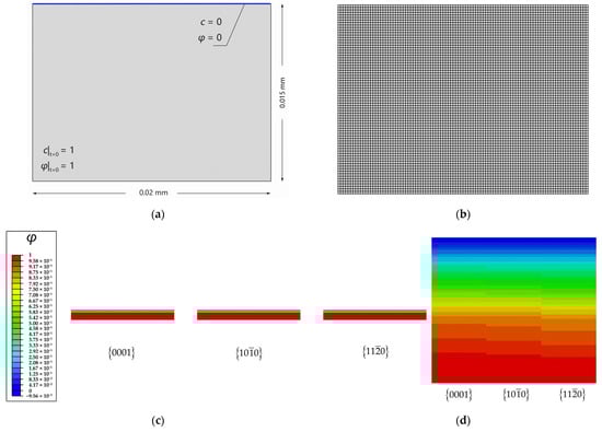
Figure 2.
Diffusion-controlled corrosion of three crystallographic planes: (a) Schematic of initial and boundary conditions for the Mg crystal with a smooth crystallographic surface exposed in the electrolyte (pure water); (b) finite element mesh; (c) corrosion of three crystallographic planes after 0.5 Ts; (d) different corrosion depth among three crystallographic planes after 0.5 Ts.

Table 1.
Material parameters for the corrosion of Mg in pure water.
The corrosion of the rectangular crystal with three different crystalline surfaces {0001}, , and (surface energy densities are listed in Table 2) is simulated. Figure 2c presents the corrosion of different crystal faces at t = 0.5 Ts. The red and blue colors correspond to the intact and completely dissolved areas, respectively. The crystallographic plane shows the greatest corrosion depth and mass loss. The diffusion-controlled corrosion from the upper surface is uniform. Figure 3 clearly shows crystal-surface corrosion rates in the order of > > {0001}. The higher the surface energy density, the stronger the diffusive ability. Song et al. [7] investigated the effect of orientations on the corrosion rate of rolled AZ31 Mg alloy by the experiments of immersion corrosion in 5 wt.% NaCl. It was found that the rolling surface, mainly consisting of {0001} crystallographic planes, was, for the first time, measured to be more electrochemically stable and corrosion-resistant than its cross-section surface, mainly composed of crystallographic planes and . The simulation results are in agreement with the experimental results and also validate the correctness of the diffusion-controlled corrosion simulation. This simulation indicates that it is feasible to regulate the corrosion rate of polycrystalline Mg based on crystal textures. For example, the rolled surface of the deformed Mg usually has a strong basal texture, and the corrosion rate will be relatively lower if the rolled surface is exposed to the corrosion solution. However, to the best of the authors’ knowledge, the formation of strong texture is detrimental to the plastic deformability. This raises another important issue of how to balance the corrosion rate and plasticity through texture modulation. To address this issue, the coupling effect of the corrosion and microstructural evolution should be considered in a polycrystalline simulation framework.
Table 2.
Surface energy density for different crystallographic planes of Mg [7].
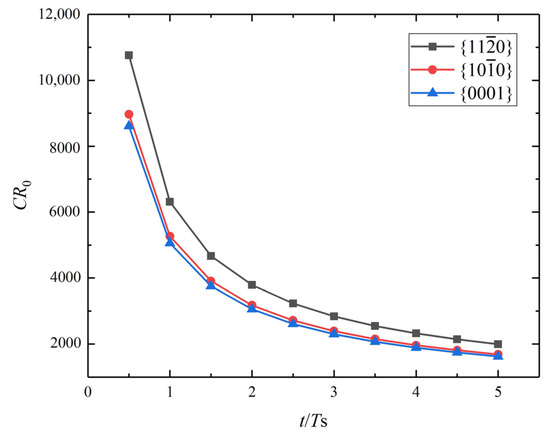
Figure 3.
Dimensionless corrosion rate versus dimensionless time for three different crystallographic planes for Mg.
3.2. Effects of Roughnesses on Diffusion-Controlled Corrosion for Mg
Bacterial infections associated with biomedical devices and implants pose a great challenge to global healthcare systems. The nanoscale rough surface of biomaterials inevitably promotes friction, resulting in low bacteria mobility. Infections are mainly caused by bacterial biofilms formed on rough surfaces. The encapsulated bacteria are quite “invisible” to conventional antibiotic treatment and attack the immune system. As it is difficult to eradicate bacterial biofilms on rough surfaces, electrochemical polishing is a promising strategy for preventing bacterial attachment, biofilm formation, and subsequent infections.
In the model with different surface roughnesses, the rough surface of a 20 × 15 μm rectangular Mg single crystal is exposed to the solution (pure water). The initial conditions of and for the Mg crystal are applied, and the Dirichlet boundary conditions of and are imposed on the rough surface, which contacts the solution (Figure 4a). The material parameters are listed in Table 1. Approximately 11,200 elements, which are quadrilateral quadratic plane strain elements with reduced integration, are used to discretize the model, and the element size is approximately 1/10 the interfacial thickness (Figure 4b).
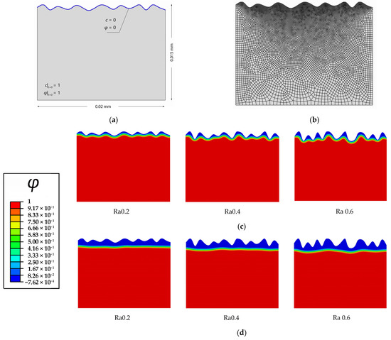
Figure 4.
Diffusion-controlled corrosion of Mg with different rough surfaces: (a) Schematic of initial and boundary conditions of Mg crystal with a rough surface exposed in pure water; (b) finite element mesh; (c) corrosion of three surfaces with different surface roughnesses Ra after 5 Ts; (d) corrosion of three surfaces with different surface roughnesses Ra after 65 Ts.
The diffusion-controlled corrosion of the rectangular Mg single crystals with surface roughnesses of Ra0.2, Ra0.4, and Ra0.6 are simulated. Figure 4c,d present the surface corrosion morphology for different surface roughness at t = 5 Ts and t = 65 Ts. It can be seen that the three different rough surfaces can be electrochemically polished to relatively smooth surfaces via diffusion-controlled corrosion. The roughest surface Ra0.6 shows the greatest corrosion depth and mass loss. Figure 5 shows that the rougher the surface is, the greater the corrosion rate is. This higher rate is caused by the shorter diffusion distance and larger limiting current density. In addition, the corrosion rates gradually drop down with corrosion time, and the corrosion tends to be uniform after the surfaces are completely polished. Gill et al. [9] investigated the effects of roughnesses on the corrosion rate of Mg-4Zn alloy by the experiments of immersion corrosion in the simulated body fluid. Samples were differentially prepared by polishing to different extents. It was concluded that polished samples showed low corrosion rates and were more uniform in simulated body fluid. The simulation results are in agreement with the experimental results [9] and validate the correctness of the diffusion-controlled corrosion in the current study. The corrosion of biomedical Mg implants before and after implantation can effectively polish the surface, thus reducing the area available for microbial adhesion and decreasing the risk of infection.
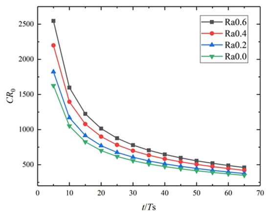
Figure 5.
Dimensionless corrosion rate versus dimensionless time for different surface roughnesses Ra.
3.3. Stress-Corrosion Coupled Damage (SCCD)
In this section, the goals of the simulation are to clarify the competition between mechanical stress and corrosion diffusion and its effect on damage evolution. As shown in Figure 6a, a 5 × 2 μm rectangular Mg single crystal, with a pre-existing surface pit exposed to the corrosion solution (pure water), is established. The corrosion pit is a semi-ellipse with a long axis of 0.4 μm and a short axis of 0.2 μm. The initial conditions of and for the Mg crystal are applied, and the Dirichlet boundary conditions of and are imposed on the surface pit, which contacts the solution (Figure 6a). The material and corrosion parameters are listed in Table 3. Approximately 5500 elements, which are quadrilateral quadratic plane strain elements with full integration, are used to discretize the model, and the element size is approximately 1/5 the interfacial thickness (Figure 6b).
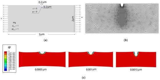
Figure 6.
SCCD of a rectangular Mg crystal: (a) geometry with initial and boundary conditions for and ; (b) finite element mesh; (c) SCCD of a rectangular Mg crystal with different displacement.
Table 3.
Mechanical and corrosion parameters of SCCD for Mg.
Figure 6c presents the differences in the lengths and shapes of the cracks at the same moment and different stress levels. Stress has a significant effect on the morphology of the SCCD. When the displacement is small, there are only elastic or small plastic strains at the pit front, damage cannot be driven by plastic work because of the existing damage energy threshold, and the diffusion-controlled corrosion slightly expands the semi-elliptical pit. When the displacement increases, the pit front stress concentration is intensified, a strong local yield occurs at the pit front, and the plastic work can drive damage and prevail in competition with the chemical potential, resulting in the rapid development of the SCCD, which is much faster than the damage driven by diffusion-controlled corrosion.
3.4. Effects of Cavities on SCCD
In this section, the goals of the simulation are to investigate the effect of defect dimensions on corrosion rate and path. The model predicts the effects of cavities on the SCCD path and rate under elastoplastic deformations and diffusion. A single crystal with two pre-existing pits is simulated. As shown in Figure 7a, the left corrosion pit is a semi-ellipse with a long axis of 0.4 μm and a short axis of 0.2 μm, and the right one is a semi-circular corrosion pit with a radius of 0.15 μm. There is a circular cavity with a radius of 0.25 μm located at the center of the single crystal. The mechanical load = 0.0022 μm is applied at the beginning of the analysis and remains constant thereafter. The material parameters for the corrosion are also listed in Table 3. Approximately 11,000 elements, which are quadrilateral quadratic plane strain elements with full integration, are used to discretize the model, and the element size is approximately 1/10 the interfacial thickness (Figure 7b).
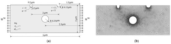
Figure 7.
Schematic of the rectangular Mg crystal: (a) geometry with initial and boundary conditions for and ; (b) finite element mesh.
The process of the SCCD is shown in Figure 8. Under the combined effects of stress and corrosion, the depth of both corrosion pits simultaneously increases at the beginning. The semi-elliptical corrosion pit on the left side is corroded more rapidly, moves towards the cavity, and then links with the cavity, finally resulting in the penetration of the entire Mg single crystal and complete loss of mechanical integrity. To further explore the effect of the cavity on the corrosion path and corrosion rate, the corrosion of the crystal with different sizes of cavities is simulated. The results show that the corrosion path gradually does not move towards the cavity with decreasing cavity size. As shown in Figure 9, the corrosion path of the crystal with the cavity size of 10 μm moves towards the central cavity at 0.5 Ts; however, it is gradually diverted from the original direction and does not connect to the cavity eventually. The corrosion path of the crystal without the cavity does not move towards the center of the single crystal at 0.5 Ts (Figure 10).
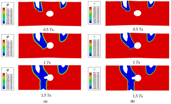
Figure 8.
The SCCD process contours of a Mg single crystal with a cavity (R = 0.25 μm): (a) phase field order parameter , (b) dimensionless concentration .
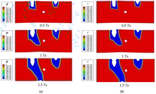
Figure 9.
The SCCD process contours of a Mg single crystal with a cavity (R = 0.1 μm): (a) phase field order parameter , (b) dimensionless concentration .
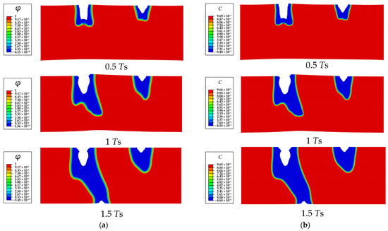
Figure 10.
The SCCD process contours of a Mg single crystal without cavity: (a) phase field order parameter , (b) dimensionless concentration .
The reason is that the cavities significantly change the stress state at the tip of the corrosion pit/crack (Figure 11). The pre-existing cavity with a larger diameter causes a greater influence on the stress states of both the crack front and the adjacent area of the cavity, which leads to the connection between the cavity and the pit. Moreover, the corrosion rate decreases as the size of the cavity increases (Figure 12). Therefore, the cavity, as a typical crystal defect, is capable of modulating the corrosion rate and the corrosion path. It indicates that defect engineering is promising for corrosion resistance enhancement.
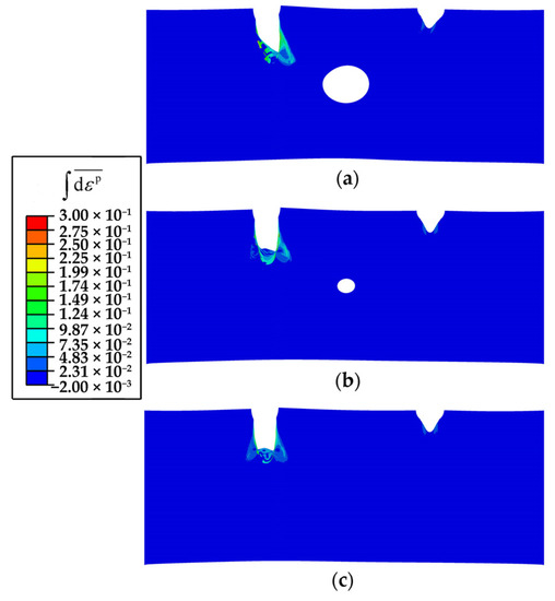
Figure 11.
The accumulative plastic strain of a Mg single crystal in the SCCD process at 0.5 Ts: (a) with a cavity (R = 0.25 μm), (b) with a cavity (R = 0.1 μm), and (c) without a cavity.
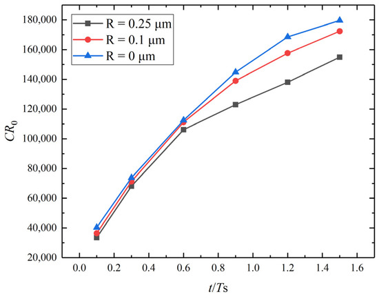
Figure 12.
Dimensionless corrosion rate versus dimensionless time for different cavity sizes.
4. Conclusions
In the current study, a phase-field scheme for modeling stress-corrosion coupled damage (SCCD) is developed. Using the finite element method, the diffusion-controlled corrosion and stress-corrosion coupled damage of the Mg crystal servicing in the corrosive environment (pure water) are numerically simulated. Three crystal-scale cases are conducted and some inspirations for the resistance design are given. Some conclusions can be drawn:
- (1)
- Crystal textures and surface roughnesses can significantly influence the diffusion-controlled corrosion rate. Higher surface energy density increases the mobility of damage diffusion and accelerates the corrosion rate. Strong basal texture, such as {0001}, of the crystal can significantly improve the corrosion resistance of Mg. Larger roughness shortens the diffusion distance and accelerates the corrosion rate. A smooth surface can effectively decrease the corrosion rate. The orientations and roughnesses can be modulated by reasonable rolling, extrusion, polishing, and so on, which are, therefore, the designable factors for corrosion resistance enhancement.
- (2)
- In the SCCD process controlled by diffusion and stress, the stress gradually prevails in competition with the diffusion, ruling the damage rate with the SCCD marching. The damage rate is much faster than the damage driven by diffusion-controlled corrosion.
- (3)
- In the SCCD process, the cavity, as a typical crystal defect, is capable of inducing the damage path and modulating the corrosion rate. The pre-existing cavity with a larger diameter is more inclined to coalesce with the propagating damage owing to its greater influence on the local stress states of both the crack front and the adjacent area of the cavity. However, the corrosion rate can be decreased due to the coalescence of the given geometric feature. It indicates that defect engineering is promising for corrosion-resistance enhancement.
Author Contributions
Conceptualization, C.X.; Methodology, J.Y. and S.B.; Software, J.Y. and S.B.; Validation, J.Y., S.B. and X.H.; Formal analysis, J.Y., S.B. and X.H.; Investigation, J.Y.; Resources, C.X.; Data curation, J.Y.; Writing—original draft preparation, J.Y. and S.B.; Writing—review and editing, J.Y. and J.C.; Visualization, J.Y., S.B. and X.H.; Supervision, C.X.; Project administration, C.X.; Funding acquisition, C.X. All authors have read and agreed to the published version of the manuscript.
Funding
This research was funded by the National Natural Science Foundation of China (No. 11872216), the Zhejiang Provincial Natural Science Foundation of China (No. Y22A021168), the Natural Science Foundation of Ningbo City (No. 202003N4083), and the Ningbo Science and Technology Major Project (Grant No. 2022Z002).
Institutional Review Board Statement
Not applicable.
Informed Consent Statement
Not applicable.
Data Availability Statement
Data available on request.
Acknowledgments
The authors are grateful for the support from the National Natural Science Foundation of China (No. 11872216), the Zhejiang Provincial Natural Science Foundation of China (No. Y22A021168), the Natural Science Foundation of Ningbo City (No. 202003N4083), and the Ningbo Science and Technology Major Project (Grant No. 2022Z002).
Conflicts of Interest
The authors declare no conflict of interest.
References
- Li, X.; Zhang, D.; Liu, Z.; Li, Z.; Du, C.; Dong, C. Materials science: Share corrosion data. Nature 2015, 527, 441–442. [Google Scholar] [CrossRef] [PubMed]
- Li, S.; Chen, Z.; Tan, L.; Bobaru, F. Corrosion-induced embrittlement in ZK60A Mg alloy. Mater. Sci. Eng. A 2018, 713, 7–17. [Google Scholar] [CrossRef]
- Ravichandran, K.; TSN, S.N. Controlling the rate of degradation of Mg using magnesium fluoride and magnesium fluoride-magnesium phosphate duplex coatings. J. Magnes. Alloy. 2022, 10, 295–312. [Google Scholar]
- Yang, Y.; Xiong, X.; Chen, J.; Peng, X.; Chen, D.; Pan, F. Research advances in magnesium and magnesium alloys worldwide in 2020. J. Magnes. Alloy. 2021, 9, 705–747. [Google Scholar] [CrossRef]
- Cui, L.Y.; Gao, L.; Zhang, J.C.; Tang, Z.; Fan, X.L.; Liu, J.C.; Chen, D.C.; Zeng, R.C.; Li, S.Q.; Zhi, K.Q. In vitro corrosion resistance, antibacterial activity and cytocompatibility of a layer-by-layer assembled DNA coating on magnesium alloy. J. Magnes. Alloy. 2021, 9, 266–280. [Google Scholar] [CrossRef]
- Esmaily, M.; Svensson, J.E.; Fajardo, S.; Birbilis, N.; Frankel, G.S.; Virtanen, S.; Arrabal, R.; Thomas, S.; Johansson, L.G. Fundamentals and advances in magnesium alloy corrosion. Prog. Mater. Sci. 2017, 89, 92–193. [Google Scholar] [CrossRef]
- Song, G.L.; Mishra, R.; Xu, Z. Crystallographic orientation and electrochemical activity of AZ31 Mg alloy. Electrochem. Commun. 2010, 12, 1009–1012. [Google Scholar] [CrossRef]
- Sabbaghian, M.; Mahmudi, R.; Shin, K.S. Effect of texture and twinning on mechanical properties and corrosion behavior of an extruded biodegradable Mg-4Zn alloy. J. Magnes. Alloy. 2019, 7, 707–716. [Google Scholar] [CrossRef]
- Gill, R.S.; Kumar, K.; Batra, U. Surface characteristics and corrosion behavior of wire electrical discharge machining processed Mg-4Zn alloy. J. Mater. Eng. Perform. 2021, 30, 2955–2966. [Google Scholar] [CrossRef]
- Jiang, L.; Wang, K.; Leng, B.; Ye, X.X.; Chen, S.J.; Liu, R.D.; Liang, J.P.; Li, C.W.; Li, Z.J. Tellurium segregation-induced intergranular corrosion of GH3535 alloys in molten salt. Corros. Sci. 2022, 194, 109944. [Google Scholar] [CrossRef]
- Ansari, T.Q.; Xiao, Z.; Hu, S.; Li, Y.; Luo, J.L.; Shi, S.Q. Phase-field model of pitting corrosion kinetics in metallic materials. NPJ Comput. Mater. 2018, 4, 38. [Google Scholar] [CrossRef]
- Mai, W.; Soghrati, S.; Buchheit, R.G. A phase field model for simulating the pitting corrosion. Corros. Sci. 2016, 110, 157–166. [Google Scholar] [CrossRef]
- Gao, H.; Ju, L.; Duddu, R.; Li, H. An efficient second-order linear scheme for the phase field model of corrosive dissolution. J. Comput. Appl. Math. 2020, 367, 112472. [Google Scholar] [CrossRef]
- Hu, Y.; Jiang, J.; Lei, M.; Song, M.; Nikbin, K. Predicting virtual creep crack growth in a simulated titanium aluminide alloy microstructure containing voids, precipitates, and grain/grain boundary distortions. Eng. Fract. Mech. 2022, 262, 108171. [Google Scholar] [CrossRef]
- Cui, C.; Ma, R.; Martínez-Pañeda, E. A phase field formulation for dissolution-driven stress corrosion cracking. J. Mech. Phys. Solids 2021, 147, 104254. [Google Scholar] [CrossRef]
- Lin, C.; Ruan, H.; Shi, S.Q. Phase field study of mechanico-electrochemical corrosion. Electrochim. Acta 2019, 310, 240–255. [Google Scholar] [CrossRef]
- Nguyen, T.T.; Bolivar, J.; Réthoré, J.; Baietto, M.C.; Fregonese, M. A phase field method for modeling stress corrosion crack propagation in a nickel base alloy. Int. J. Solids Struct. 2017, 112, 65–82. [Google Scholar] [CrossRef]
- Lin, C.; Ruan, H. Phase-field modeling of mechano-chemical-coupled stress-corrosion cracking. Electrochim. Acta 2021, 395, 139196. [Google Scholar] [CrossRef]
- Nguyen, T.T.; Bolivar, J.; Shi, Y.; Réthoré, J.; King, A.; Fregonese, M.; Adrien, J.; Buffiere, J.Y.; Baietto, M.C. A phase field method for modeling anodic dissolution induced stress corrosion crack propagation. Corros. Sci. 2018, 132, 146–160. [Google Scholar] [CrossRef]
Publisher’s Note: MDPI stays neutral with regard to jurisdictional claims in published maps and institutional affiliations. |
© 2022 by the authors. Licensee MDPI, Basel, Switzerland. This article is an open access article distributed under the terms and conditions of the Creative Commons Attribution (CC BY) license (https://creativecommons.org/licenses/by/4.0/).