Article

Crystallographic Origin of Phase Transformation and Lamellar Orientation Control for TiAl-Based Alloys

1
MIIT Key Laboratory of Advanced Metallic and Intermetallic Materials Technology, Engineering Research Center of Materials Behavior and Design, Ministry of Education, Nanjing University of Science and Technology, Nanjing 210094, China
2
School of Materials Science and Engineering, University of Science and Technology, Beijing 100083, China
*
Author to whom correspondence should be addressed.
Crystals 2022, 12(5), 634; https://doi.org/10.3390/cryst12050634
Submission received: 29 March 2022 / Revised: 23 April 2022 / Accepted: 26 April 2022 / Published: 28 April 2022
(This article belongs to the Special Issue Processing, Structure and Properties of TiAl Alloys)

Abstract

:
TiAl intermetallics are typical metallic materials involving complex solid-state phase transformations, with crystal orientations that are difficult to control due to multi-transformation variants. However, lamellar orientation control is crucial to the development of a polysynthetic twinned single crystal structure in TiAl-based alloys for jet engines or other high-temperature systems. In this study, β-solidifying TiAl alloys were used to study the relationships between the lamellar structure and the phase transformation process under directional solidification (referred to as the directional phase transformation, DPT). It was found that the β → α phase transition affects the lamellar orientations and that the subsequent process of α → α2 + γ leads to the final formation of the polysynthetic lamellar structure. Detailed analyses based on crystallography show that the β/α phase interface is responsible for the different oriented lamellar structures with the 0° or 45° orientation. With a lower interfacial energy, the 0° oriented α phase nucleates more easily but grows much more slowly than the 45° oriented α phases during DPT, which makes it feasible to control the lamellar orientations for TiAl-based alloys. The crystallographic origin for the control of lamellar orientations was then studied and confirmed by using EBSD in a β-solidifying Ti–Al–Nb alloy.

1. Introduction

TiAl intermetallic alloys possess the excellent properties of being light weight, high in strength and corrosion resistant, making them adequate substitutes for Ni-based superalloys for use at high temperatures above 600 °C [1,2,3,4,5,6,7,8,9,10]. After decades of development, the polycrystalline TiAl alloys have been successfully introduced into GEnx and PW1134G engines as low-pressure turbine (LPT) blades, bringing the benefits of weight reduction, fuel efficiency and lower emissions [1,2,3,4,8,9]. However, further attempts to improve their high-temperature properties by taking the step from polycrystalline to single-crystal alloys have been impeded because of the uncontrollable crystal orientations of TiAl alloys. During the past several decades, great efforts have been made to control the lamellar orientations of TiAl polysynthetic twinned (PST) single crystals consisting of α2-Ti3Al and γ-TiAl phases. However, most of these have failed, except for those which have used a seeding method [11,12,13,14,15]. The difficulty lies in the two consecutive solid-state phase transformations involved, namely, β → α and α → α2 + γ (β and α are disordered b.c.c. and h.c.p., respectively, α2 and γ are ordered D019 type h.c.p. and ordered L10 type f.c.c., respectively). The crystal orientations of these two processes follow the well-known Burgers and Blackburn orientation relationship (OR) of {110}β‖{0001}α‖{111}γ, <111>β‖<11 2 ¯ 0>α‖<110>γ [16,17]. Because the final lamellar structure is generated from phase transformations rather than from solidification, the lamellar orientations cannot be controlled through directional solidification. The α-solidifying TiAl alloys (α is the primary phase on solidification) were used to fabricate the well-aligned PST single crystals in the seeded directional solidification (DS) method because this case involved only one phase transformation process of α → α2 + γ upon cooling. However, in the case of the β-solidifying TiAl alloys (β is the primary phase on solidification), which involve two phase transformation processes upon cooling, control of the lamellar orientations was considered impossible to achieve [18,19].
Research on the solid-state phase transformations in TiAl-based alloys have revealed that the alloy component and cooling rate are the most important factors that affect the transformation process and the final microstructure. The widely accepted four typical room-temperature microstructures of gamma alloys were obtained by controlling the transformation process of α → α2 + γ [5]. Because the product of this phase transformation can be obtained at room temperature, most studies have been focused on this route. By contrast, the β → α transformation, which occurs at a relatively higher temperature with little room-temperature product, has received little attention. Furthermore, the phase transformations in TiAl-based alloys have always been studied under the condition of conventional solidification with a three-dimensional heat flux, which is quite different from the one-dimensional temperature field under directional solidification. That is why the current research cannot control the lamellar orientations without using the seeded directional solidification method. Thus, it is necessary for us to study the phase transformation process under directional solidification (directional phase transformation, DPT).
Our previous study on PST TiAl single crystal has shown that the β-solidifying TiAl alloys can be used to fabricate well-aligned lamellar structures [4]. The purpose of this study is to conduct a more detailed analysis based on crystallography for the DPT process of β-solidifying TiAl alloys, aiming to explore the crystallographic origins of the control of lamellar orientations during DPT through β → α and α → α2 + γ phase transformations. Theoretical calculations and model analyses were mainly used to study the phase transformation process. After that, electron backscatter diffraction (EBSD) was adopted to characterize the crystal orientation relationships for different oriented lamellar structures.

2. Materials and Methods

The extended Burgers vector content (BVC) method was used to calculate the misfit of the β/α phase interface [20], and the graphical method based on the free software PTC Lab was adopted to demonstrate the atomic misfit of the β/α phase interface and the atomic shifts model of β → α phase transformation [21]. The β-solidifying Ti-Al-Nb alloys were used for the electron backscatter diffraction (EBSD) test, which were prepared from high-purity Ti, Al and Nb elements, using vacuum induction magnetic levitation melting. Since Nb is known to reduce the twin interface stacking fault energy, increase the tendency of mechanical twinning [22], and thus improve the ductility and strength of TiAl alloys, we added Nb to TiAl alloys. Directional solidification was conducted in a Bridgman-type apparatus to acquire PST TiAl single crystals with the 0° and 45° oriented lamellar structures. The experimental conditions and process were reported in our previous study [4]. Small disks with a thickness of 1 mm were cut from the single-crystal bars for electron the backscatter diffraction (EBSD) test, which were electron polished using the electrolytes of 10% Perchloric acid in Ethanol at 25 V for 30 s. A scan step of 3 μm was adopted in EBSD imaging. The EBSD data were further analyzed with commercial software OIM Analysis (Ver. 8). Energy-dispersive X-ray spectroscopy (EDS) within a scanning electron microscope (SEM) was used to characterize the composition. The EBSD and SEM-EDS tests were conducted in a Zeiss Auriga crossbeam (FIB-SEM) workstation.

3. Results and Discussion

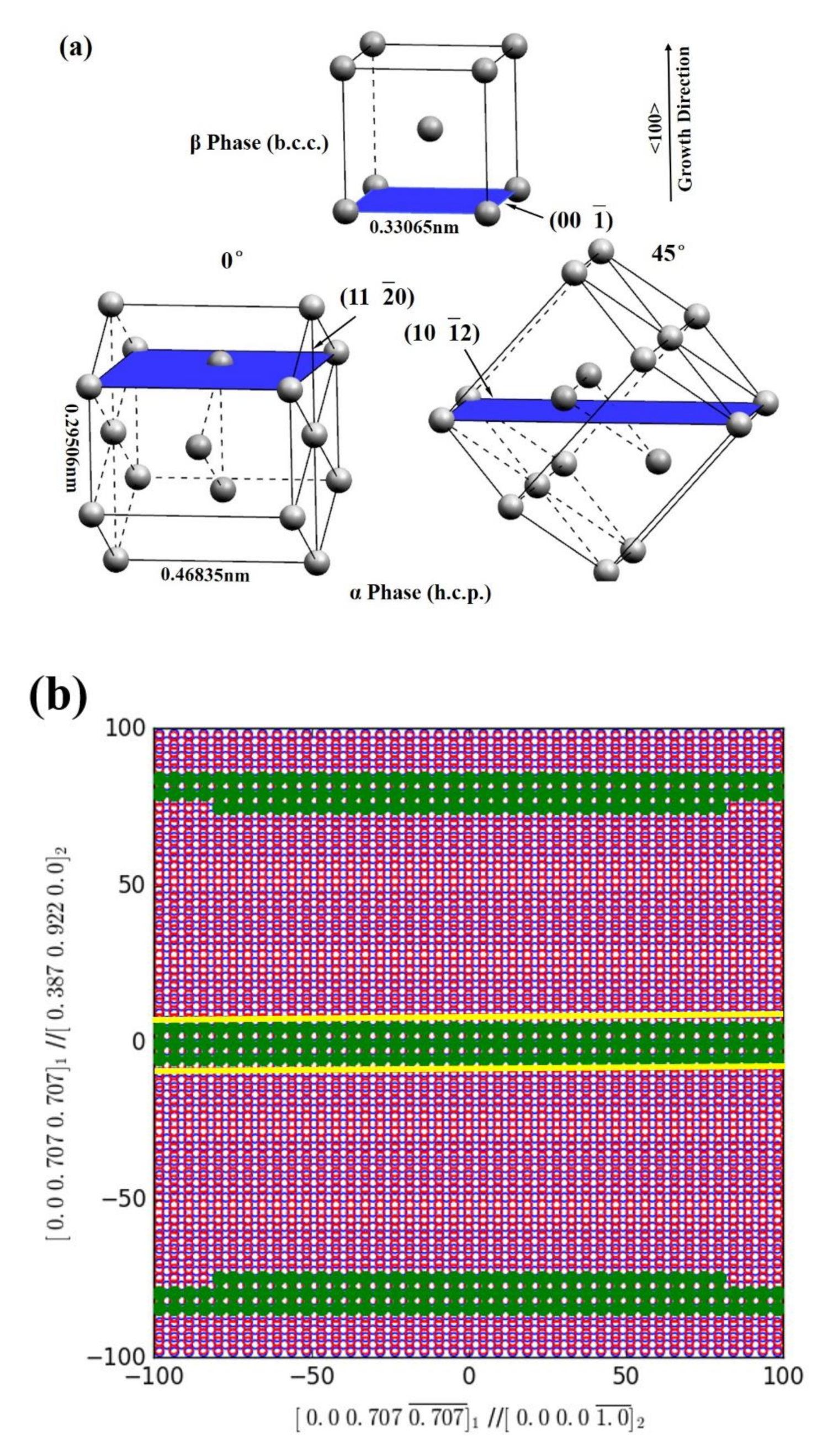
3.1. Anisotropy of β/α Interfacial Energy

As pointed out previously [4], the β → α transformation decides the final lamellar orientations during the DPT process (Figure 1): for β-solidifying alloys, different oriented α phases will be generated from the β matrix with its <001> parallel to the growth direction, which makes the final lamellae grow at an angle of 0° or 45° to the growth direction (Figure 1a–c). Considering the Burgers OR between β and α phases, since there are six close packet planes {011} and two close packed directions <1 1 ¯ 1> on each plane in the b.c.c. β phase, it will give a maximum of 12 variants of orientations for the α phase growing, within which only four variants form the lamellar structure, i.e., the interface {011}β‖{0001}α, aligned parallel to the growth direction (marked by red box in Figure 1), with the other eight variants inclining 45° to the growth direction. For α-solidifying alloys, which do not go through the β → α transformation, the α2/γ lamellae are aligned perpendicular to the growth direction (Figure 1d), since α phase growth occurs along <0001> direction upon solidification.
Generally, in the β-solidifying TiAl-based alloys, the 45° oriented lamellar structures are formed more easily than the 0° oriented because of the probability (eight variants vs. four variants). The β and α phases in the structure that grow along the 0° or 45° directions have the same crystal parameters, except at the β/α phase interface. Compared with the 0° growing case, the 45° oriented α phase rotates to grow at 45°, while the [001] direction of the β phase keeps parallel to the growth direction, leading to the different atomic arrangement around the phase interface between β and α phases. We have previously discovered that the β/α interfaces are (00 1 ¯ )β‖(11 2 ¯ 0)α for the 0° growing α phase and (00 1 ¯ )β‖(10 1 ¯ 2)α for the 45° growing case, as shown in Figure 2a. The lattice parameters for the α and β phases are aα = 0.29506 nm, cα = 0.46835 nm and aβ = 0.33065 nm according to the literature [23,24].
We than used the extended BVC method to calculate the misfit for these two types of interfaces. The crystallographic orientation relationship of the interfaces for calculation is shown in Figure 2b,c for the 0° and 45° oriented lamellar structures, respectively. The calculation process is as follows.
A vector xβ in b.c.c phase is transformed to a corresponding vector xα in h.c.p. lattice during β → α phase transformation, and these two vectors could be linked by the transformation matrix A as follows:
xα = A xβ
in a common orthogonal coordinate system, such as x‖[100]β, y‖[010]β and z‖[001]β. For the Burgers OR, (0001)α‖(0 1 ¯ 1)β, [1 1 ¯ 00]α‖[2 1 ¯ 1 ¯ ]β, [11 2 ¯ 0]α‖[111]β discussed here, the transformation matrix A could be calculated as:
0.8886 0.07091 0.07091,
−0.05789 1.04495 0.04337,
−0.05789 0.04337 1.04495,
according to the lattice correspondence specified in [25]. The displacement between any vector xβ and its transformation product xα is as follows:
Δx = xαxβ= xαA−1 xα= (I − A−1)xα= Txα
where T is the so-called displacement matrix, and Δx is the so-called BVC in the direction of xα according to famous Frank–Bilby equation. For the transformation matrix A in Equation (2), the displacement matrix is as follows:
0.11589 −0.07271 −0.07271,
0.05936 −0.04523 −0.04365,
0.05936 −0.04365 −0.04523,
If we set the length of the displacement equal to 1, i.e., |Δx| = 1, the locus of vector xα lies in an ellipsoid specified by the following:
ΔxΔx = xα′T′Txα = 1
this is due to the anisotropic nature of the three-dimensional transformation strain. The misfit strain could be evaluated as follows:
ε = |Δx|/|xα| = 1/|xα|
Since the displacement is fixed, the major axis of the ellipsoid has a minimum misfit strain and serves as the best matching direction in three-dimensional space, which is [01 1 ¯ ]β in the present case. Considering the misfit in a planar interface, the displacement vectors for this interface will lie in one plane, i.e., a cross-section of the ellipsoid. Therefore, we can evaluate the misfit for an interface by comparing the area of the cross-section. The larger the area, the smaller the misfit of the interface. Based on this, the area of the ellipse intersected by the (00 1 ¯ )β‖(11 2 ¯ 0)α interface with the ellipsoid in the 0° oriented lamellar structure is 146 nm2, and 26 nm2 for the (00 1 ¯ )β‖(10 1 ¯ 2)α interface in the 45° oriented lamellar structure, which indicates a lower misfit for the 0° growing interface.
This can be demonstrated by a graphical method using free software PTC Lab. Setting |Δx| = 15%|bβL|, where bβL is the Burgers vector of the β phase, the atoms in the interface with a misfit smaller than 15%|bβL| are highlighted by solid green circles as shown in Figure 2b,c, where red open circles represent the atoms in the β phase and blue open circles represent atoms in the α structure. The green circles are also called good matching sites or near coincidence sites. The envelope of the green circles is the ellipse mentioned above, which is intersected by the (00 1 ¯ )β‖(11 2 ¯ 0)α or (00 1 ¯ )β‖(10 1 ¯ 2)α interface with the ellipsoid (Equation (5)) and is marked by yellow lines in Figure 2b,c. Better matching in the interface means it contains more good matching sites. Comparing Figure 2b,c, it is easy to find that the ellipse in Figure 2c is clear while the good matching area in Figure 2b is nearly rectangular for the 0° growing (00 1 ¯ )β‖(11 2 ¯ 0)α interface. This is because the area of the ellipse in Figure 2c (the 45° growing interface) is much smaller than that in Figure 2b (the 0° growing interface), and the ellipse intersected by the (00 1 ¯ )β‖(11 2 ¯ 0)α interface in Figure 2b is elongated, which is due to the small misfit in the [01 1 ¯ ]β direction, which the complete ellipse cannot present in this view. Therefore, the (00 1 ¯ )β‖(11 2 ¯ 0)α interface has a better matching, indicating that the 0° growing interface has a lower interfacial energy than that of the 45° one.

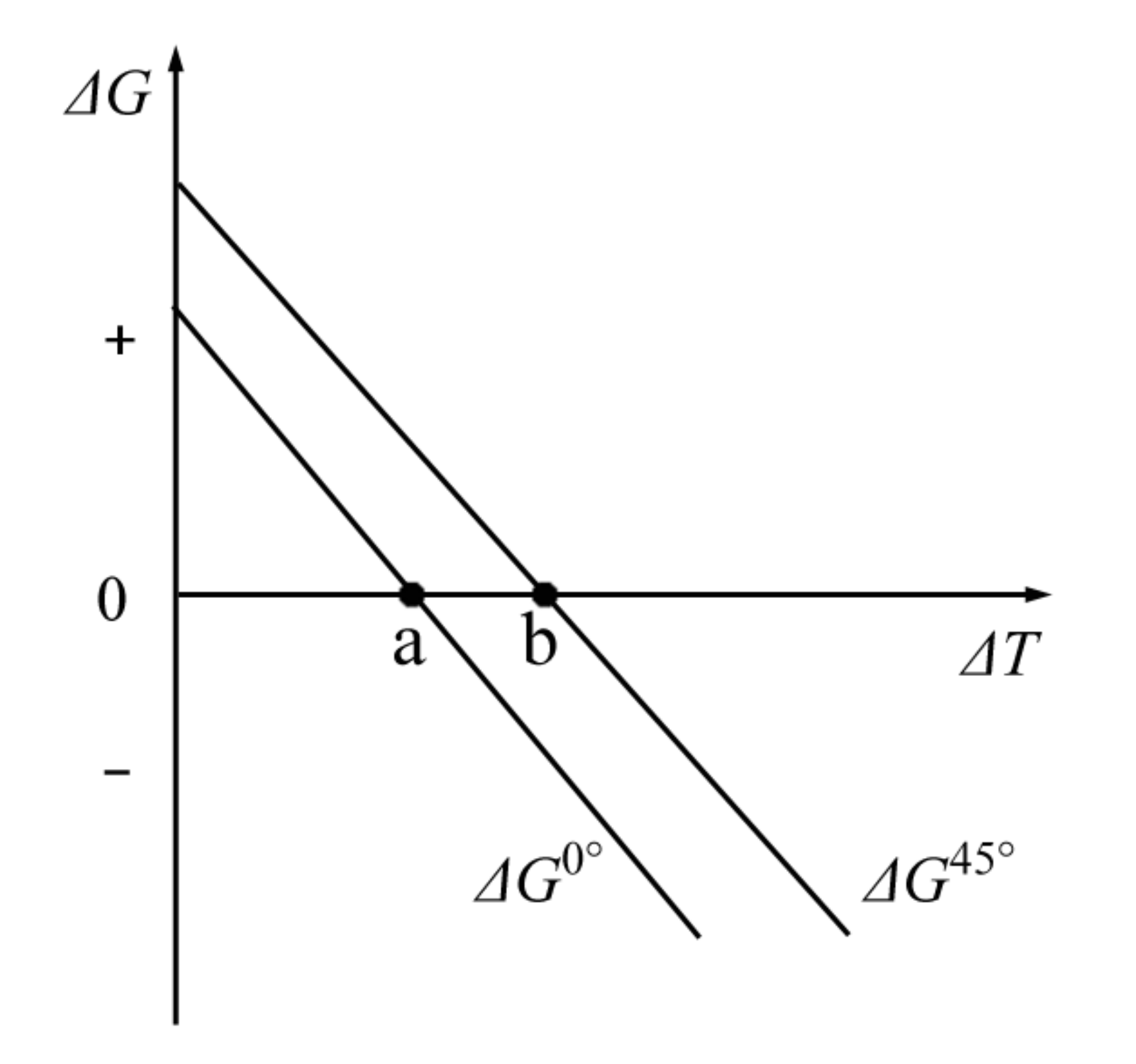
3.2. Thermodynamics and Kinetics

The different β/α interfacial energy between the 0° and 45° lamellar structure means that the lamellar orientations do not appear randomly but selectively. This theoretical analysis can be improved further based on the thermodynamics and kinetics theory of phase transformation. Most solid-state phase transformations take place by nucleation and growth [26], and the β → α transformation is also in this category. The effects of the different β/α interfaces during the β → α transformation based on the nucleation and growth process are different.
When the α phase nucleates from the β matrix, there is a Gibbs free energy change, which is as follows [26]:
ΔG = −VΔGv + Aγ + VΔGs
The three contributions of the free energy change are the following:
  • the creation of a volume V of α, which causes a volume free energy reduction of VΔGv;
  • the creation of an area A of β/α interface, which gives a free energy increase of Aγ;
  • the creation of a volume V of α, which gives rise to a misfit strain energy of VΔGs.
Among the three contributions in the free energy change, the volume free energy reduction (VΔGv) is a driving force for nucleation, while the increase in the β/α interfacial energy (Aγ) and the misfit strain energy (VΔGs) provides the resistance to nucleation. When the α phase nucleates from the β phase, the crystal orientation relationship has nothing to do with the volume free energy and the misfit strain energy. The only factor that is relevant to the crystal orientation is the boundary energy per unit area γ. In a conventional solidification procedure, phase transformation proceeds in three-dimensional space, so the variation of γ with interface orientation can be ignored. However, the DPT proceeds in a two-dimensional plane with the axial direction being controlled, meaning the γ plays a different role. Because the temperature field in the directional solidification apparatus is arranged along the axial direction and the volume free energy reduction is caused by the temperature change, the driving force is also parallel to the axial direction. Therefore, different β/α interfaces, which mean different interfacial energy γ perpendicular to the driving force direction, do have an important impact on the nucleation. In addition, the lower interfacial energy of the β/α interface (00 1 ¯ )β‖(11 2 ¯ 0)α than that of the (00 1 ¯ )β‖(10 1 ¯ 2)α interface indicates that the 0° lamellar α phase has a lower nucleation barrier than the 45° one, which means that the 0° lamellar structure forms more easily than the 45° at the same nucleation undercooling (ΔT). This can be seen from the free energy change (ΔG)—undercooling (ΔT) curve as shown in Figure 3. From the curve we can see that the 0° growing case has a smaller y-intercept than that of the 45° but both exhibit the same slope, due to this lower nucleation barrier and same driving force, respectively. Therefore, the x-intercept for the 0° growing case is smaller than that of the 45°, indicating that the critical nucleation undercooling for 0° growing α phase (point a) is lower than the 45° (point b). If we control the undercooling between a and b, there will only be the 0° oriented growing α phase’s nucleation, leading to the formation of a parallel lamellar structure. Therefore, we can control the lamellar orientations parallel to the growth direction, as compared to the probability of 1/3 for getting a 0° oriented lamellar structure, if all variants appear.
If the nucleation undercooling is sufficient for both the 0° and 45° oriented growing α phase (ΔT > b), the 45° oriented lamellar structure is acquired in most cases, although the 0° growing α phase can nucleate more easily than the 45°. This can be explained in the growth stage of β → α transformation. Once nucleated, the α nuclei grow into the surrounding β matrix by thermally activated migration of interfaces. The force that drives the migration of interfaces comes from the pressure difference caused by a curved interface which can be given by the following [26]:
F = 2 γ r
where F is the pulling force per unit area and r is the radius of curvature of the grain. Furthermore, considering the impact of the driving force on the kinetics of interface migration, the velocity of interface migration is written as follows [26]:
v = MF
where M is the mobility of the interface. M is mainly affected by the temperature and the component of the interface. Therefore, the velocity of interface migration v is proportional to the interfacial energy γ. During the growth stage after nucleation, the 0° growing α grains will grow at a lower rate than the 45° growing α grains due to the lower γ of the (00 1 ¯ )β‖(11 2 ¯ 0)α interface as compared with the (00 1 ¯ )β‖(10 1 ¯ 2)α interface. When the grown α grains collide with each other, the big one will annex the small ones because of the pressure difference caused by interface curvatures. Therefore, we get 45° oriented lamellar structure rather than 0° in this case.
The degree of undercooling increases with the increased cooling rate during DPT, while the cooling rate (C) is calculated as the product of the thermal gradient (G) and the withdrawal rate (V), C = G × V. This means that the nucleation of the grains can be controlled by regulating V while G remains constant [27]. Based on our analysis above, there must exist a critical withdrawal rate Vc, below which the 0° growing α grains can nucleate but the 45° ones cannot, thus the 0° oriented lamellar structure can be obtained at a withdrawal rate lower than Vc, while the 45° oriented lamellae can be obtained at a withdrawal rate higher than Vc. This prediction has been verified in our previous work [4].

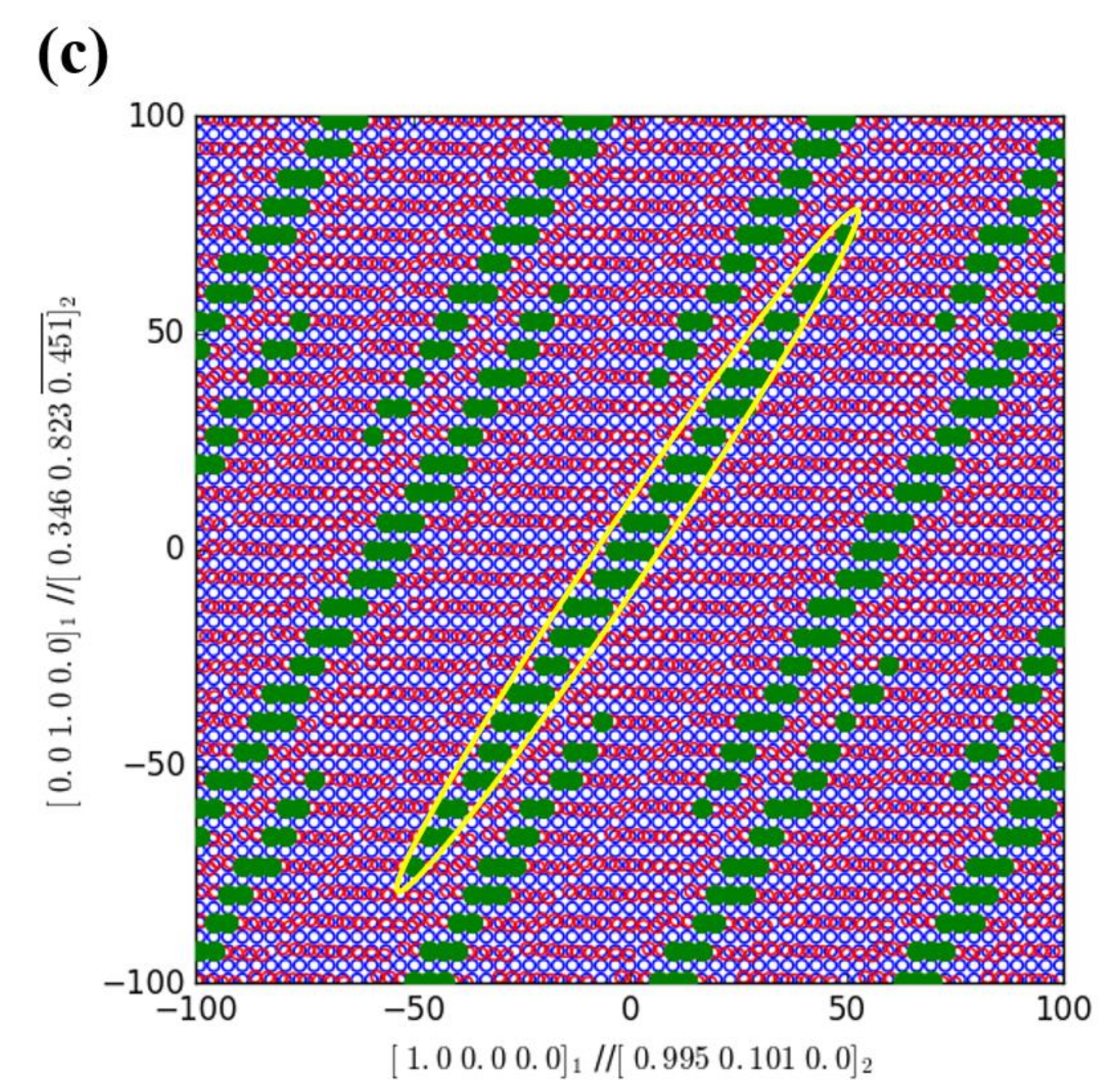
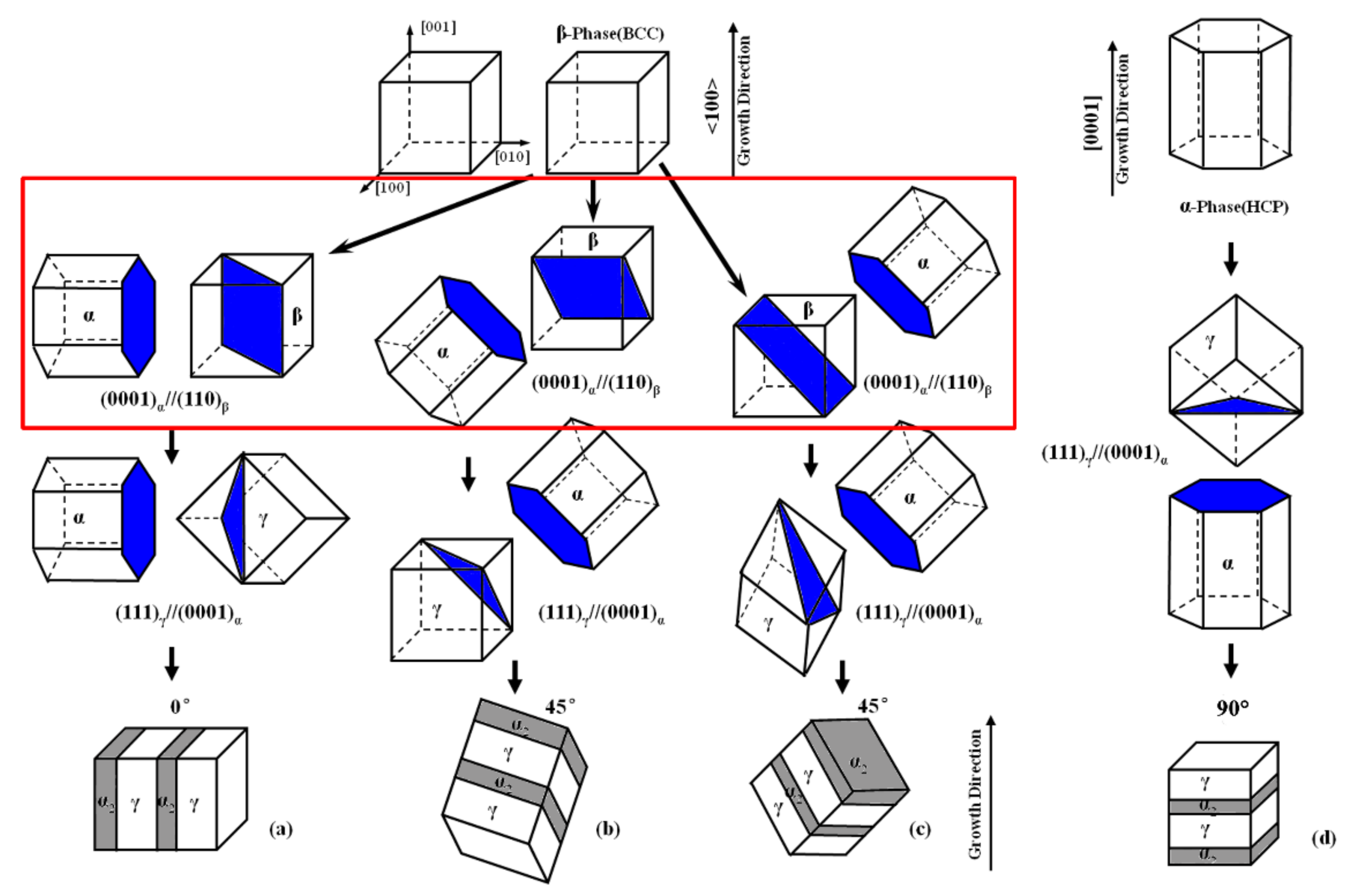
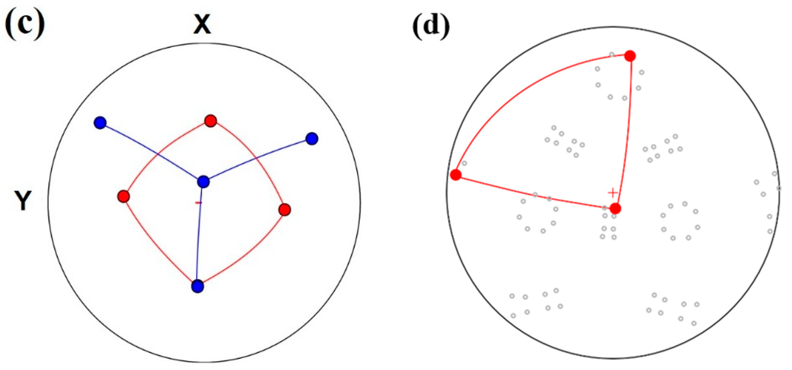
3.3. Crystallography

W. G. Burgers has investigated the process of b.c.c. β to h.c.p. α transition from crystallography [16]. Based on his shearing mechanism at Pitsch OR, the angle of 109°28′ (70°32′) between the two <111> directions in a {110} plane in the b.c.c. lattice changes into the angle of 120° (60°) between two <11 2 ¯ 0> directions of the hexagonal lattice by Bain strain [28], as shown in Figure 4a,b. For each α unit cell, atoms are shifted over the same distance. When the basal plane of the α phase is inclined at an angle of 0° or 45° to the axial direction during DPT, the distance that atoms are shifted will have different projective components in the axial direction (parallel to the growth direction) and the horizontal direction (perpendicular to the growth direction) (Figure 4c,d). The shift distance component of atoms in one basal plane of the α unit cell is calculated as follows. According to the lattice parameters for the α and β phases [23,24], for the 0° growing α phase, the six atoms in the basal plane are shifted over a total distance, the axial component and a horizontal component of which are as follows:
4 a β a α = 0.14236   nm
and
2 3 a α 2 a β = 0.086898   nm
Likewise, the axial component and horizontal component of the 45° growing α phase are as follows:
6 a α 2 a β = 0.061446   nm
and
4 a β a α 2 + 6 a α 2 a β 2 + 2 a β a α = 0.16521   nm
Based on the above calculations for the processing of β → α transformation, atoms for the 0° oriented α phase shift over a longer distance in the axial direction but a shorter distance in the horizontal direction than the 45° oriented α phase. A shorter atom-shift distance in the horizontal direction exactly proves that the misfit of the β/α interface of the 0° growing α phase is smaller than that of the 45°. Also, the longer atom-shift distance in the axial direction indicates that the 0° α phase has a slower progress of β → α transformation than the 45° in the axial direction, which corresponds to the lower migration rate of the β/α interface of 0° α grains in the axial direction. Therefore, the crystallographic model agrees well with the thermodynamic and kinetic analysis.
Since we used Ti-Al-Nb alloys for further study in this work, we shall discuss the effect of Nb on interfacial energy anisotropy and crystallography next. Firstly, the β and α phases in TiAl alloys are both high-temperature disordered phases without preferential sites for Ti, Al and Nb atoms. Therefore, no previous studies have reported the effect of Nb addition on lattice parameters for these two phases, either theoretically or experimentally. Secondly, since Nb atoms are reported to occupy Ti sites in γ-TiAl and α2-Ti3Al phases [29], both of which are ordered phases, the effect of Nb addition on lattice parameters has been studied by molecular dynamics simulations and experiments elsewhere [30,31]. It was found that 8 at. %-Nb addition has little influence on the lattice parameters for both γ-TiAl and α2-Ti3Al phases. Therefore, we may conclude that Nb addition makes little difference to β and α phases’ lattice parameters, thus having little effect on interfacial-energy anisotropy and crystallography for the β → α transformation.
By analyzing the free energy change of the β → α phase transformation for TiAl-based alloys, we find that different oriented α phases will lead to a different nucleation barrier due to the different misfit values of the β/α interfaces. Therefore, the parallel lamellar structure can be fabricated by controlling the nucleation undercooling of directional solidification [32]. More importantly, this free-energy-control theory can be applied broadly to many other solid-state phase transformations such as the β (b.c.c)→α (h.c.p) transition in Zr, Hf and Co, or the γ (b.c.c) → γ’ (f.c.c) transition in Ni-Al alloys (Ni-based supperalloys) and the β (b.c.c) → α (f.c.c) transition in Cu–Zn alloys (brass).

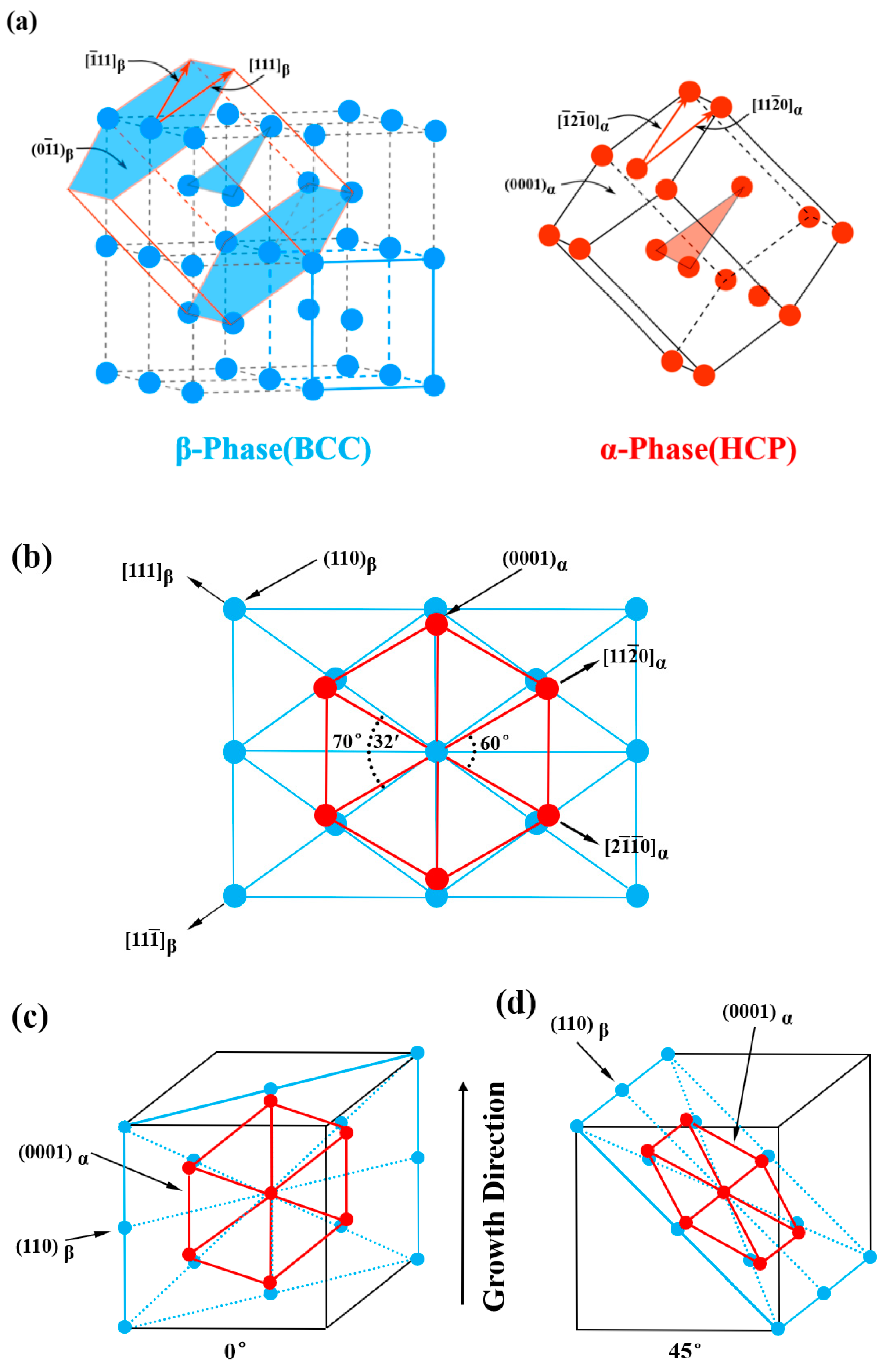
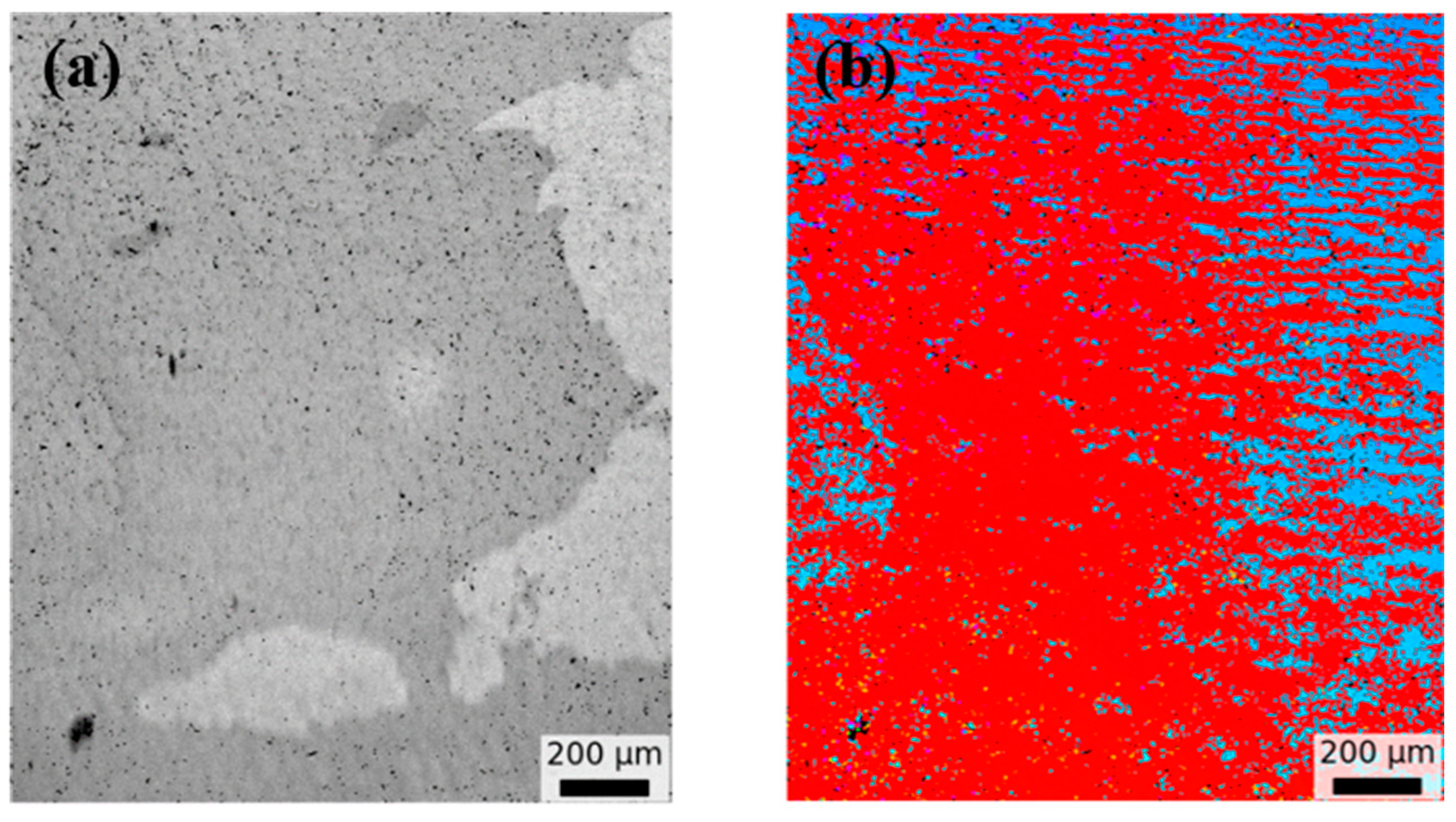
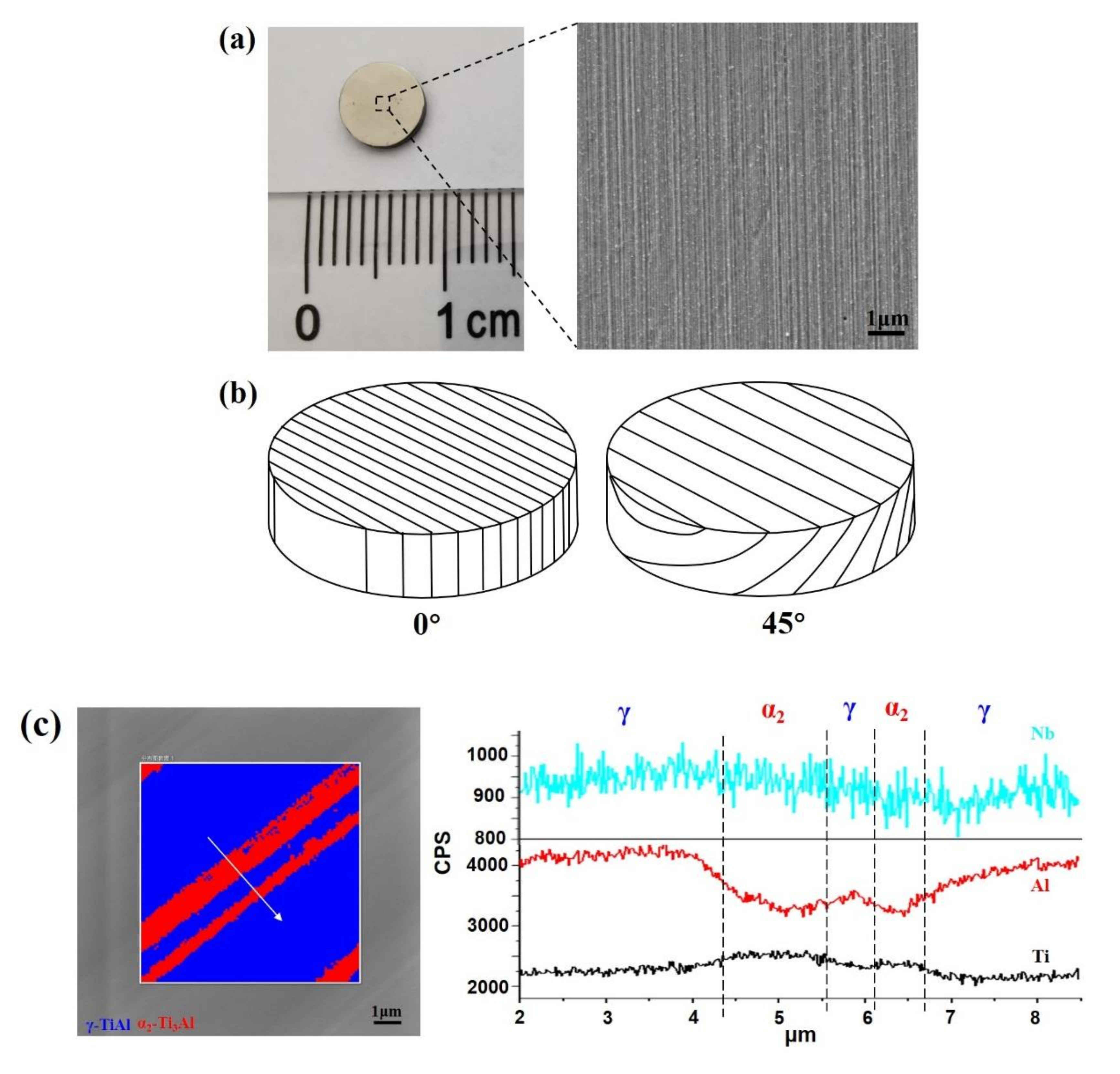
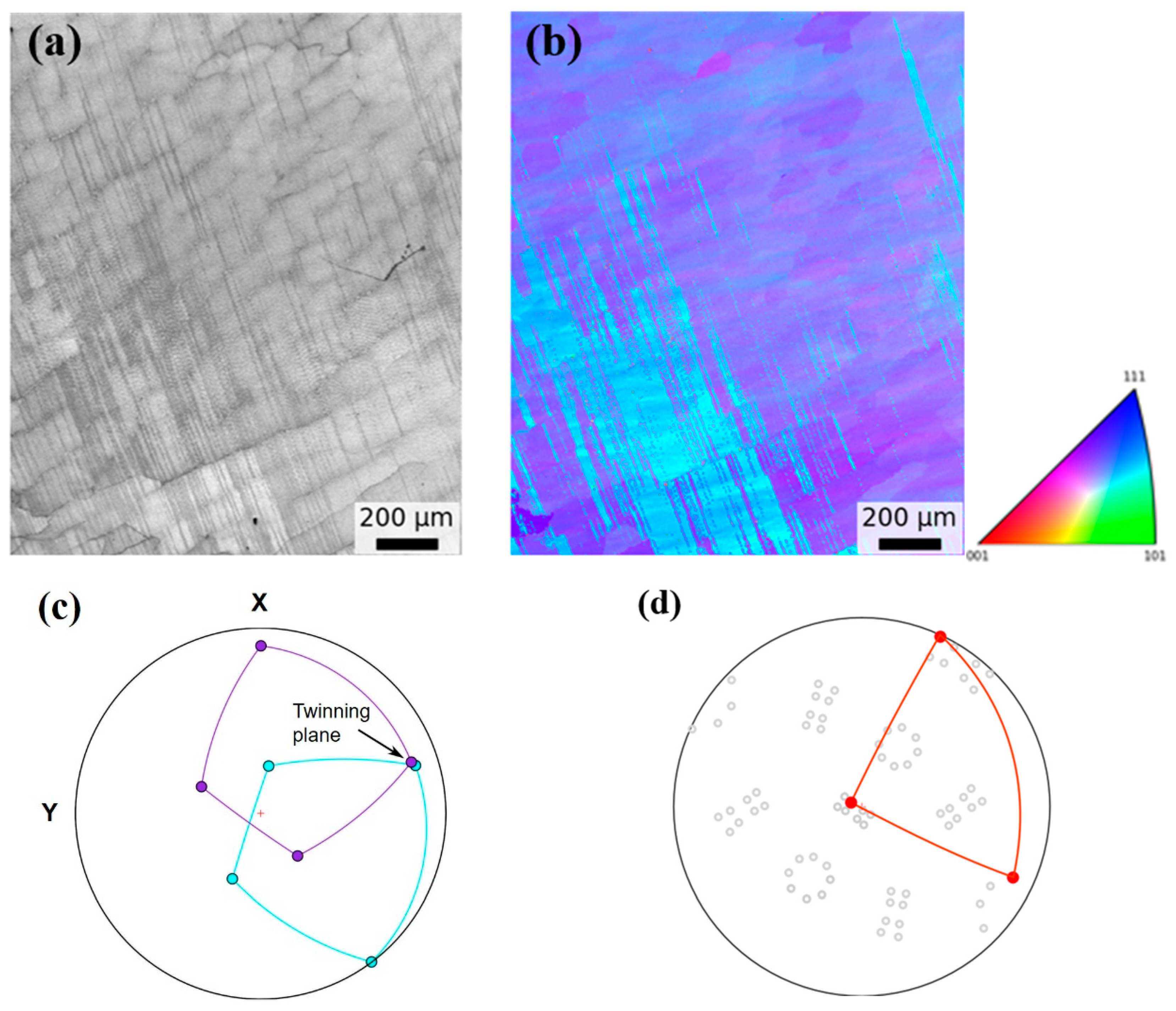
3.4. EBSD Characterization of Different Oriented Lamellar Structures

Based on our previous study [4], we have successfully acquired the 0° and 45° oriented TiAl lamellae through DPT. Small disks were cut from single-crystal bars and shown in Figure 5a, from which the lamellar structures can be seen. It is found that the TiAl lamellae are so refined that the α2 and γ phases can hardly be identified—the lamellar spacing can be as small as hundreds of nanometers, as we have reported elsewhere [33,34]. The schematics of disk samples with 0° and 45° oriented lamellae are shown in Figure 5b, based on which the EBSD characterization was conducted. The composition of the α2 and γ phases was also characterized by SEM-EDS (Figure 5c and Table 1), showing that Nb was slightly partitioning to the γ phases.
To validate our prediction about the β → α phase transformation and lamellar orientation relationship above, we analyzed the 0° and 45° oriented TiAl lamellae by EBSD. By checking the crystal orientation of α2 and γ lamellae, we were able to deduce reversely the crystal orientation of high-temperature α and β phases. If our analyses were right, the deduced β orientation of the 0° and 45° oriented sample should be the same, that is, the <100> direction (Figure 1a,b). The results are shown in Figure 6 and Figure 7. In EBSD mapping over 1mm2, mainly the γ phase is detected due to the fine α2 phase. During β → α and α → α2 + γ transformation, the OR {110}β‖{0001}α‖{111}γ, <111>β‖<1120>α‖<110>γ holds; thus, possible orientations of β could be deduced from the orientation of the γ phase. Furthermore, the growth direction of the β phase is along <100>β; accordingly, the orientation of the β phase should be consistent with this condition. EBSD results for a 0° oriented sample are shown in Figure 6, and the lamellae interface is parallel to the {111}γ twin plane. The reconstructed orientation of the β phase is shown in Figure 6d as {001}β pole figure, and one of {001}β poles is close to the growth direction (normal direction). Similarly, the orientation of the β phase could be determined for a 45° oriented sample as shown in Figure 7. Again, it is consistent with the growth direction of the β phase along {001}β. Therefore, our deduction of the crystallographic relationship for β → α and α → α2 + γ phase transformation during DPT was reliable.

4. Conclusions

In this work, the β-solidifying TiAl alloys were used to study how solid-state phase transition β → α and α → α2 + γ affect the formation and evolution of lamellar structures in the process of DPT. By analyzing the relationships between lamellar orientations and crystal orientations, we found that it is the phase transformation β → α that affects the final orientations of lamellar structures, and further analysis showed that the β/α phase interface determines whether the lamellar orientation is 0° or 45°. With a lower misfit value of the phase interface, the 0° oriented interface has a lower interfacial energy than the 45°. According to the thermodynamics and kinetics theory of phase transformation, the new phase is formed due to nucleation and growth, during which the interfacial energy is the resistance for nucleation but a driving force for growth. Therefore, the 0° oriented α lamellar grains nucleate more easily but grow more slowly than the 45° ones, which was further verified based on crystallographic analysis. According to these derivations, we believe that the TiAl lamellar orientations can be controlled by controlling the nucleation and growth of different oriented α phases during DPT, which has already been accomplished in our previous study [4,30,31,32,33,34,35]. Furthermore, this interfacial energy criterion may find applications in some other solid-state phase transformations in metals or alloys.

Author Contributions

Conceptualization, G.Z.; methodology, G.Z., H.P. and X.G.; validation, Z.J., Y.C. (Yang Chen) and Z.Q.; investigation H.X., F.C. and Y.C. (Yuede Cao); data curation, C.F.; writing—original draft preparation, G.Z., H.P. and X.G.; writing—review and editing, G.Z. and Z.Q.; supervision, G.C. All authors have read and agreed to the published version of the manuscript.

Funding

This research was supported by the National Natural Science Foundation of China (Grant No. 91860104, 51731006, 51771093, 92163215, 52174364 and 52101143), the National Postdoctoral Program for Innovative Talents (Grant No. BX201700120), Natural Science Foundation of Jiangsu Province Major Project (Grant No. BK20212009), Open Project Program of Key Laboratory of China North Engine Research Institute (6142212210103), Yang Chen was supported by Postdoctoral Program of Jiangsu Province.

Institutional Review Board Statement

Not applicable.

Informed Consent Statement

Not applicable.

Data Availability Statement

Not applicable.

Conflicts of Interest

The authors declare no conflict of interest.

References

  1. Pollock, T.M. Alloy design for aircraft engines. Nat. Mater. 2016, 15, 809–815. [Google Scholar] [CrossRef] [PubMed]
  2. Plummer, J. Understanding a way to fly high. Nat. Mater. 2016, 15, 819–820. [Google Scholar] [CrossRef] [PubMed]
  3. Schütze, M. High-temperature alloys: Single-crystal performance boost. Nat. Mater. 2016, 15, 823–824. [Google Scholar] [CrossRef] [PubMed]
  4. Chen, G.; Peng, Y.B.; Zheng, G.; Qi, Z.X.; Wang, M.Z.; Yu, H.C.; Dong, C.L.; Liu, C.T. Polysynthetic Twinned TiAl Single Crystals for High Temperature Applications. Nat. Mater. 2016, 15, 876–881. [Google Scholar] [CrossRef] [PubMed]
  5. Kim, Y.W. Ordered intermetallic alloys, part III: Gamma titanium aluminides. JOM 1994, 46, 30–39. [Google Scholar] [CrossRef]
  6. Clemens, H.; Kestler, H. Processing and Applications of Intermetallic γ-TiAl-Based Alloys. Adv. Eng. Mater. 2000, 2, 551–570. [Google Scholar] [CrossRef]
  7. Lasalmonie, A. Intermetallics: Why is it so difficult to introduce them in gas turbine engines? Intermetallics 2006, 14, 1123–1129. [Google Scholar] [CrossRef]
  8. Liu, C.T.; Schneibel, J.H.; Maziasz, P.J.; Wright, J.L.; Easton, D.S. Tensile properties and fracture toughness of TiAl alloys with controlled microstructures. Intermetallics 1996, 4, 429–440. [Google Scholar] [CrossRef]
  9. Bewlay, B.P.; Weimer, M.; Kelly, T.; Suzuki, A.; Subramanian, P.R. The Science, Technology, and Implementation of TiAl Alloys in Commercial Aircraft Engines. MRS Proc. 2013, 1516, 49–58. [Google Scholar] [CrossRef]
  10. Janschek, P. Wrought TiAl Blades. Mater. Today Proc. 2015, 2, S92–S97. [Google Scholar] [CrossRef]
  11. Johnson, D.R.; Inui, H.; Yamaguchi, M. Directional solidification and microstructural control of the TiAl/Ti3Al lamellar microstructure in TiAl-Si alloys. Acta Mater. 1996, 44, 2523–2535. [Google Scholar] [CrossRef]
  12. Takeyama, M.; Yamamoto, Y.; Morishima, H.; Koike, K.; Chang, S.Y.; Matsuo, T. Lamellar orientation control of Ti-48Al PST crystal by unidirectional solidification. Mater. Sci. Eng. A 2002, 329–331, 7–12. [Google Scholar] [CrossRef]
  13. Johnson, D.R.; Masuda, Y.; Inui, H.; Yamaguchi, M. Alignment of the TiAl/Ti3Al lamellar microstructure in TiAl alloys by growth from a seed material. Acta Mater. 1997, 45, 2523–2533. [Google Scholar] [CrossRef]
  14. Yokoshima, S.; Yamaguchi, M. Fracture behavior and toughness of PST crystals of TiAl. Acta Mater. 1996, 44, 873–883. [Google Scholar] [CrossRef]
  15. Yamaguchi, M.; Johnson, D.R.; Lee, H.N.; Inui, H. Directional solidification of TiAl-base alloys. Intermetallics 2000, 8, 511–517. [Google Scholar] [CrossRef]
  16. Burgers, W.G. On the process of transition of the cubic-body-centered modification into the hexagonal-close-packed modification of zirconium. Physica 1934, 1, 561–586. [Google Scholar] [CrossRef]
  17. Blackburn, M.J. The Science, Technology, and Application of Titanium; Jaffee, R.I., Promisel, N.E., Eds.; Pergamon Press: Oxford, UK, 1970; p. 663. [Google Scholar]
  18. Kim, M.C.; Oh, M.H.; Lee, J.H.; Inui, H.; Yamaguchi, M.; Wee, D.M. Composition and growth rate effects in directionally solidified TiAl alloys. Mater. Sci. Eng. A. 1997, 239, 570–576. [Google Scholar] [CrossRef]
  19. Jung, I.S.; Jang, H.S.; Oh, M.H.; Lee, J.H.; Wee, D.M. Microstructure control of TiAl alloys containing β stabilizers by directional solidification. Mater. Sci. Eng. A. 2002, 329, 13–18. [Google Scholar] [CrossRef]
  20. Gu, X.F.; Zhang, W.Z.; Qiu, D. A systematic investigation of the development of the orientation relationship in an fcc/bcc system. Acta Mater. 2011, 59, 4944–4956. [Google Scholar] [CrossRef]
  21. Gu, X.F.; Furuhara, T.; Zhang, W.Z. PTC Lab: Free and open-source software for calculating phase transformation crystallography. J. Appl. Crystallogr. 2016, 49, 1099–1106. [Google Scholar] [CrossRef]
  22. Edwards, T.E.J.; Di Gioacchino, F.; Mohanty, G.; Wehrs, J.; Michler, J.; Clegg, W.J. Longitudinal twinning in a TiAl alloy at high temperature by in situ microcompression. Acta Mater. 2018, 148, 202–215. [Google Scholar] [CrossRef]
  23. Grytsiv, A.; Rogl, P.; Schmidt, H.; Giester, G. Constitution of the ternary system Al-Ru-Ti (Aluminum-Ruthenium-Titanium). J. Phase Equilib. 2003, 24, 511–527. [Google Scholar] [CrossRef]
  24. Schuster, J.C.; Palm, M. Reassessment of the binary aluminum-titanium phase diagram. J. Phase Equilib. Diff. 2006, 27, 255–277. [Google Scholar] [CrossRef]
  25. Ye, F.; Zhang, W.Z.; Qiu, D. A TEM study of the habit plane structure of intragrainular proeutectoid α precipitates in a Ti–7.26 wt% Cr alloy. Acta Mater. 2004, 52, 2449–2460. [Google Scholar] [CrossRef]
  26. Porter, D.A.; Easterling, K.E.; Sherif, M.Y. Phase Transformations in Metals and Alloys; CRC Press: Boca Raton, FL, USA, 2009. [Google Scholar]
  27. Elliott, A.J.; Pollock, T.M.; Tin, S.; King, W.T.; Huang, S.C.; Gigliotti, M.F.X. Directional solidification of large superalloy castings with radiation and liquid-metal cooling: A comparative assessment. Metall. Mater. Trans. A 2004, 35, 3221–3231. [Google Scholar] [CrossRef]
  28. Dahmen, U. Orientation relationships in precipitation systems. Acta Metall. 1982, 30, 63–73. [Google Scholar] [CrossRef] [Green Version]
  29. Hao, Y.L.; Xu, D.S.; Cui, Y.Y.; Yang, R.; Li, D. The site occupancies of alloying elements in TiAl and Ti3Al alloys. Acta Mater. 1999, 47, 1129–1139. [Google Scholar] [CrossRef]
  30. Yan, S.; Qi, Z.X.; Chen, Y.; Cao, Y.D.; Zhang, J.P.; Zheng, G.; Chen, F.R.; Bian, T.; Chen, G. Interlamellar boundaries govern cracking. Acta Mater. 2021, 215, 117091. [Google Scholar] [CrossRef]
  31. Hou, R.; Zheng, G.; Chen, G. Microstructure stability of PST TiAl single crystal subjected to long-term thermal exposure. Acta Mater. 2022; submitted. [Google Scholar]
  32. Chen, G.; Zheng, G.; Qi, Z.X.; Zhang, J.P.; Li, P.; Cheng, J.L.; Zhang, Z.W. Research progress on controlled solidification and its applications. Acta Metall. Sin. 2018, 54, 669–681. [Google Scholar]
  33. Chen, Y.; Cao, Y.D.; Qi, Z.X.; Chen, G. Increasing high-temperature fatigue resistance of polysynthetic twinned TiAl single crystal by plastic strain delocalization. J. Mater. Sci. Technol. 2021, 93, 53–59. [Google Scholar] [CrossRef]
  34. Wang, D.P.; Qi, Z.X.; Zhang, H.T.; Chen, G.; Lu, Y.; Sun, B.A.; Liu, C.T. Microscale mechanical properties of ultra-high-strength polysynthetic TiAl-Ti3Al single crystals. Mater. Sci. Eng. A 2018, 732, 14–20. [Google Scholar] [CrossRef]
  35. He, N.; Qi, Z.X.; Cheng, Y.X.; Zhang, J.P.; He, L.L.; Chen, G. Atomic-scale investigation on the interface structure of {2201} α2-Ti3Al deformation twins in polysynthetically twinned TiAl single crystals. Intermetallics 2021, 128, 106995. [Google Scholar]
Figure 1. Relationships between lamellar orientations and crystal orientations of TiAl-based alloys during DPT. (ac) 0° and 45° oriented lamellae acquired through β → α and α → α2 + γ phase transformation for β-solidifying TiAl alloys, (d) 90° oriented lamellae acquired through α → α2 + γ phase transformation for α-solidifying TiAl alloys [4].
Crystals 12 00634 g001
Figure 2. (a) Atomic arrangement and phase interface of the b.c.c. β and the h.c.p. α phase, (b) the atomic misfit of the (00 1 ¯ )β‖(11 2 ¯ 0)α interface in the 0° lamellar structure, (c) the atomic misfit of the (00 1 ¯ )β‖(10 1 ¯ 2)α interface in the 45° lamellar structure. Red open circles represent the atoms in b.c.c. β phase, blue open circles are for atoms in h.c.p. α structure. Solid green circles indicate the good matching sites within the interface, which are marked and surrounded by yellow lines.
Crystals 12 00634 g002aCrystals 12 00634 g002b
Figure 3. Variation of the free energy change (ΔG) with nucleation undercooling (ΔT) for 0° or 45° oriented growing α phase.
Crystals 12 00634 g003
Figure 4. Schematic of atomic shifts for the b.c.c. β to h.c.p. α phase transition during DPT. (a) the h.c.p. lattice derives from the b.c.c. lattice, (b) atomic shifts model for β → α transformation, (c,d) the 0° and 45° oriented α phase have different atomic shift projective components in the axial direction (parallel to the growth direction) and the horizontal direction (perpendicular to the growth direction) during DPT.
Crystals 12 00634 g004
Figure 5. (a) small disk of TiAl lamellar sample; right side is the enlarged SEM image of lamellar structures, (b) schematic of the 0° and 45° oriented lamellae, (c) SEM-EDS of γ and α2 lamellae.
Crystals 12 00634 g005
Figure 6. EBSD results on the plane normal to the growth direction for 0° oriented sample. (a) image quality, (b) corresponding orientation image (IPF-y), (c) {111}γ pole figure of two twin related variants in (b), (d) {001}β pole figure showing reconstructed orientation of β phase based on orientation relationship.
Crystals 12 00634 g006
Figure 7. EBSD results on the plane normal to the growth direction for 45° oriented sample. (a) image quality, (b) corresponding orientation image (IPF-z), (c) {111}γ pole figure of two twin related variants in (b), (d) {001}β pole figure showing reconstructed orientation of β phase based on orientation relationship.
Crystals 12 00634 g007aCrystals 12 00634 g007b
Table 1. The composition of γ-TiAl and α2-Ti3Al phases.
PhaseTiAlNb
γ-TiAl49.1541.549.31
α2-Ti3Al59.1132.558.34
Publisher’s Note: MDPI stays neutral with regard to jurisdictional claims in published maps and institutional affiliations.

