Article

Effective Case Depth and Wear Resistance of Pack Carburized SCM 420 Steel Processed Using Different Concentrations of Natural Shell Waste Powders and Carburizing Duration

Mechanical Engineering Department, Southern Taiwan University of Science and Technology, Tainan 71005, Taiwan
*
Author to whom correspondence should be addressed.
Crystals 2022, 12(2), 296; https://doi.org/10.3390/cryst12020296
Submission received: 30 January 2022 / Revised: 13 February 2022 / Accepted: 17 February 2022 / Published: 19 February 2022
(This article belongs to the Special Issue Advances in High Strength Steels)

Abstract

:
The efficacy of using coconut shell powder (CSP) and dog conch shell powder (DCSP) as an alternative carburizing media for SCM 420 steel pack carburization was investigated. The effective case depth and wear resistance of quenched specimens prepared using various CSP–DCSP ratios and carburizing times were determined and compared. The effective case depth was measured from the microhardness profile obtained using a Vickers hardness testing machine. A CSP–DCSP ratio of 60%:40% and carburization time of 12 h were found to increase the effective case depth of SCM 420 quenched specimens to 2340 µm. The results clearly showed that the effective case depth increased by increasing carburization time and DCSP concentrations from 0% to 40% as a carburizing media and decreased by further increasing DCSP concentrations to 50%. Moreover, the wear resistance of quenched specimens increased approximately two times as DCSP concentrations were increased from 0% to 40% for a carburization time of 12 h.

1. Introduction

While engineering materials are constantly evolving, their use is determined by their availability, cost, mechanical properties such as wear resistance, corrosion resistance, durability, and other functional requirements [1]. Low carbon steel such as SCM 420 is frequently used for machinery construction and moving components such as shafts, racks and gears, pinions, cams, rockers, axles, valves, and so on due to its availability, cost-effectiveness, ductility, and toughness [2,3,4,5]. However, this engineering material has some limitations, most notably in terms of hardness, strength, and wear resistance. Consequently, surface treatment is frequently used in real-life applications to ensure that components meet required performance requirements [6]. Pack carburizing treatment is frequently used to achieve a high surface hardness while retaining the core material’s natural toughness and ductility [7,8]. Notably, the component’s material properties can be optimized by varying the duration and temperature of the carburizing process [9,10,11,12]. Generally speaking, a higher carburizing temperature and a longer carburizing time result in a thicker effective case depth and thus a higher surface hardness.
Several studies proved that casehardening mild steel increases its case hardness, thereby increasing its wear resistance; the thicker the case depth, the harder the mild steel. This improves the performance and durability of the mild steel material as a moving part compared to the untreated mild steel component [13,14]. There are a variety of carburizing materials available, each with a unique carburizing potential; however, some have a low carburizing potential. The carburizing potential of these low carburizing potential materials can be increased through the use of energizers. These energizers increase the carburizing potential of the carburizing material [13]. Ihom et al. noticed that the effective case depth is a good measure of carbon penetration and, thus, that the depth of case hardening can be used to determine an energizer’s efficacy [14]. Additionally, he stated that according to the International Standard Organization’s ISO 2639-1973 and SS 1170 08 standards, depth case is defined as the distance from the surface to a plane with a hardness of 550 Hv [14,15].
Various carbonates are used as energizers in the carburizing process; barium carbonate (BaCO3), sodium carbonate (NaCO3), and calcium carbonate (CaCO3) are notable examples. These are combined with the carbonaceous material in various percentages [16,17,18,19,20,21,22]. In recent years, calcium carbonate from some industrial waste such as fly ash, slag, and other hot raw material has been used for steel processing. Jiang et al. [23] used fly ash material to investigate the bonding behavior between steel and geopolymer paste (GPC) at very high elevated temperatures. Calcium carbonate from various natural shells and bones has also been considered as the energizer source for carburization. Soenoko et al. [24] and Darmo et al. [25] used teak wood charcoal and Pomacea canaliculata Lamarck (PCL) shell powder as the carbonaceous material source and energizing source, respectively, to pack carburize SS400 steel cylinders. The results indicated that the addition of PCL shell power increased the hardness and fatigue performance of the SS400 components effectively. Negara and Widiyarta [26] used goat bone charcoal (GBC) and bamboo charcoal (BC) as the carburizing media to pack carburize low carbon steel. The results indicated that by selecting an appropriate carburizing medium (i.e., GBC or BC), significant improvements in hardness, tensile strength, yield strength, and elastic modulus could be obtained. Aramide et al. [27] discovered that adding pulverized bone as an energizer enhanced the impact resistance and stiffness of carburized mild steel specimens. Ihom et al. [14] revealed that mild steel could be casehardened utilizing a carbonaceous material and eggshell combination as an energizer, achieving a case depth of 0.75 mm after several hours of carburizing. They noticed that the effective case depth achieved during casehardening is related to the holding time.
At present, many researchers use shells and bones as energizers for the carburizing process. However, few researchers have considered using seafood shells to enhance the pack carburizing process. In the previous work [28,29], the present group discovered the feasibility of using seafood shells (i.e., dog conch shells) as an alternative energizer for the packed carburization process of SCM 420 steel. However, the investigations are still limited on the hardness value and carbon content of carburized specimens. Therefore, the present study investigates the effective case depth, total case depth, and wear resistance of SCM 420 specimens carburized using different carburizing medium concentrations and carburizing times.
The objective of this study was to investigate the effective case depth, total case depth, and wear resistance of SCM 420 specimens carburized using various dog conch shell powder (DCSP) and coconut shell powder (CSP) concentrations as a carburizing medium for carburization durations of 3, 6, and 12 h, respectively. The carburizing temperature is fixed at 950 °C for each experiment, and the DCSP content is varied in the range of 0~50%. Generally, dog conch and coconut shells are discarded as waste. Thus, reusing them as an enhancing source in the carburization process gives an alternative earth-friendly way for steel processing. Hence, this study significantly contributes to environmental benefits.

2. Materials and Methods

SCM 420 steel bars with a diameter and length of 20 mm and 50 mm were used in carburizing trials. The samples were placed in a 240 × 120 × 80 mm3 (length × width × height) low carbon steel carburizing box with a 5 mm thickness. The experiments were performed with various CSP–DCSP percentage ratios. The carbon content of the original SCM 420 steel is about 0.22 wt.% [28]. The various percentages of carburizing media are shown in Table 1.
The coconut shell powder-activated carbon from the company was repeatedly washed with distilled water to remove contaminants and then dried overnight in a furnace at 60 °C. Before powdering, the dog conch shell was immersed in a 10% H2SO4 solution for 6 h, then repeatedly washed with distilled water and dried in an oven at 60 °C for 24 h to remove impurities. Each experiment began with adding the specified amount of carburizing media (CSP and DCSP) to the box, which was then placed in an electric furnace and heated to 950 °C for 3, 6, and 12 h, respectively. To prevent the formation of an oxidation layer on the carburized sample surface, nitrogen gas was continuously circulated through the furnace during the entire carburization process. After the carburizing process, the samples were allowed to cool naturally to room temperature in the electric furnace, then reheated for 10 min at a temperature of 950 °C, according to Fe–C equilibrium diagram and austenitizing temperature commonly used for low to medium carbon steel [24,30,31,32], and rapidly quenched in water.
For a microhardness measurement preparation, the quenched samples were machined into test pieces, then ground step by step up to 1200 grit SiC paper and polished using a motor-driven disk grinder and polisher to clean and smooth out the surface. Microhardness measurements of all the specimens were performed using a Vickers hardness testing machine (Wilson Hardness Tukon 1102, Shanghai, China) under a 1 kgf load. Microhardness measurements were made starting from the surface, at an interval of 100 µm to a certain distance toward the center. To ensure the reliability of the measurement results, the microhardness was measured five times (using a new sample each time) for every experimental condition. A representative value for the sample was obtained by averaging the five measurement results. From the average microhardness values obtained for each specimen, the microhardness profiles were plotted, and effective case depths of various DCSP concentrations and carburizing time were extracted.
The carbon content along the quenched specimens carburized layer was measured three times per layer using glow discharge spectrometry (GDS) (Leco-GDS500A, Michigan, MI, USA), with a distance of 100 µm between each layer. Prior to performing GDS analysis on every layer, the samples were ground using 120-grit ZrO2 paper, washed in distilled water and alcohol, and then dried with an air compressor to remove the impurities. The phase of quenched specimens was determined using X-ray diffractometry (XRD) (Bruker D2 Phaser, Karlsruhe, Germany) using CuKα radiation with a diffraction angle range of 20~80°. The microstructures and chemical compositions of the carburized specimen were identified by Scanning Electron Microscopy (SEM) machine (Hitachi S-3000N, Tokyo, Japan) with a detector energy dispersive spectroscopy (EDS) (X-maxN20, Horiba Ltd., Tokyo, Japan). Furthermore, the microstructures of the carburized layer were also observed using optical microscopy (Olympus BX51M, Tokyo, Japan).
The wear resistance of the samples was detected using pin-on-disk wear testing apparatus. The wear test sample preparation and procedure followed the methodology and procedure of ASTM G99 [33]. The wear resistance of the specimens was performed using pin-on-disk wear testings at temperatures of ±23 °C with a load of 20N, wear track (nominal) diameter of 5 mm, and sliding speed of around 0.018 m/s (70 rpm). The wear test runs for approximately 182 min or about three hours with a sliding distance of 200 m. Following the procedure of ASTM G99, the SCM 420 quenched specimens were cut into the thickness of 5 mm and ground to surface roughness of around 0.8 µm. Prior to testing and weighing, the wear test specimens were cleaned and dried for one minute using an ultrasonic cleaning machine to remove all foreign matter and dirt from the samples. The mass loss was determined by weighing specimens before and after the test with a 0.1 mg sensitivity balance. To ensure the reliability of the data, mass loss was measured five times for each experimental condition (using a new sample each time). After averaging the five measurement results, a representative value for the sample was determined. According to ASTM G99, the mass loss value of the specimen converted to volume loss by using the best available density value of the specimens. The wear width is determined by scaling SEM micrographs of the worn surfaces of samples. Furthermore, the wear depths can be estimated by dividing wear volume by the wear width of specimens.

3. Results and Discussion

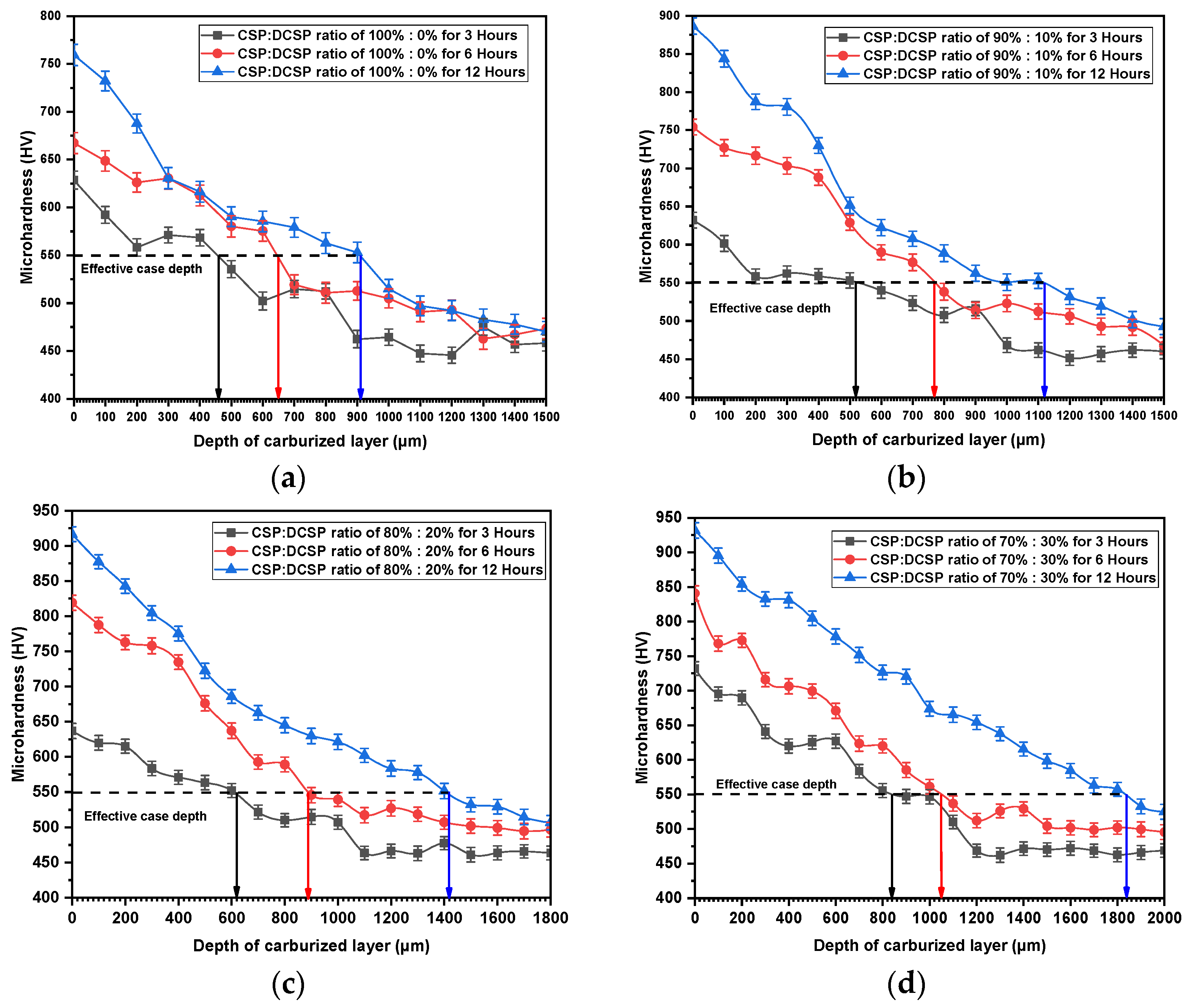
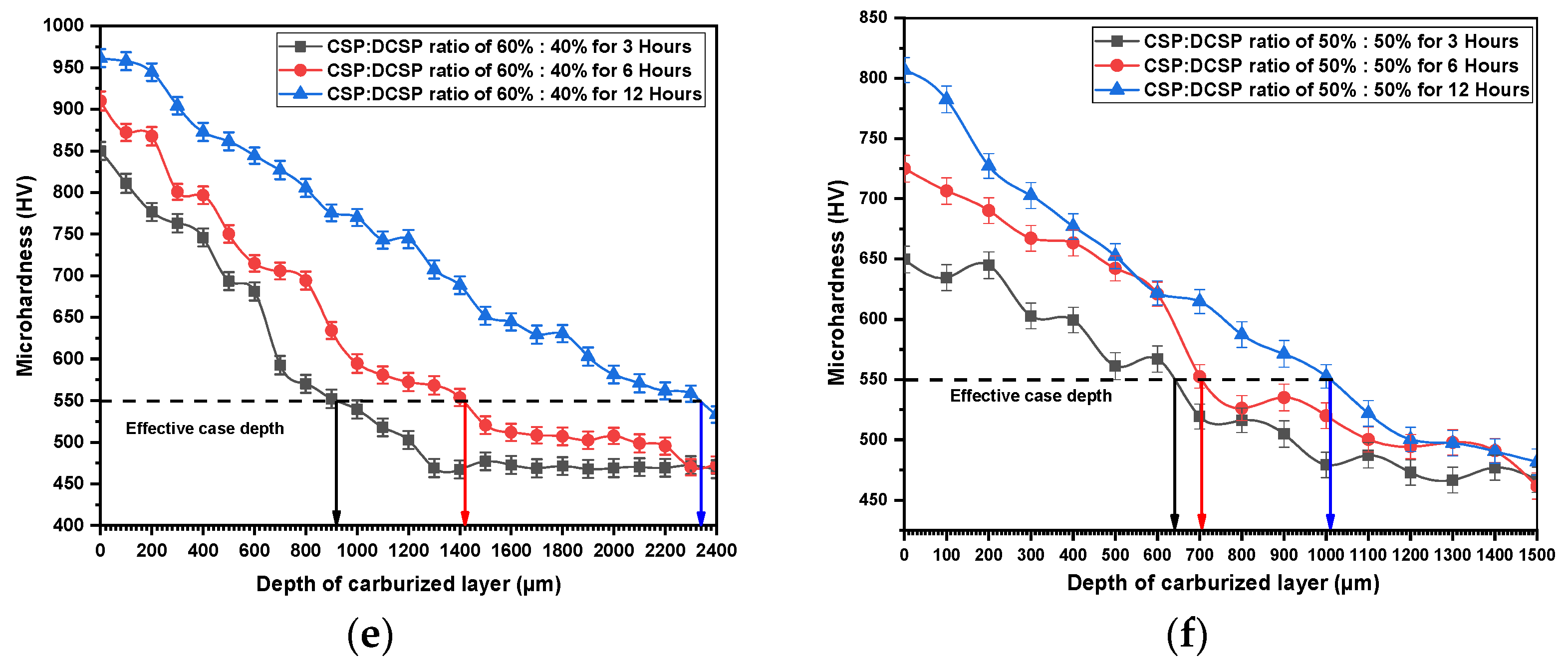
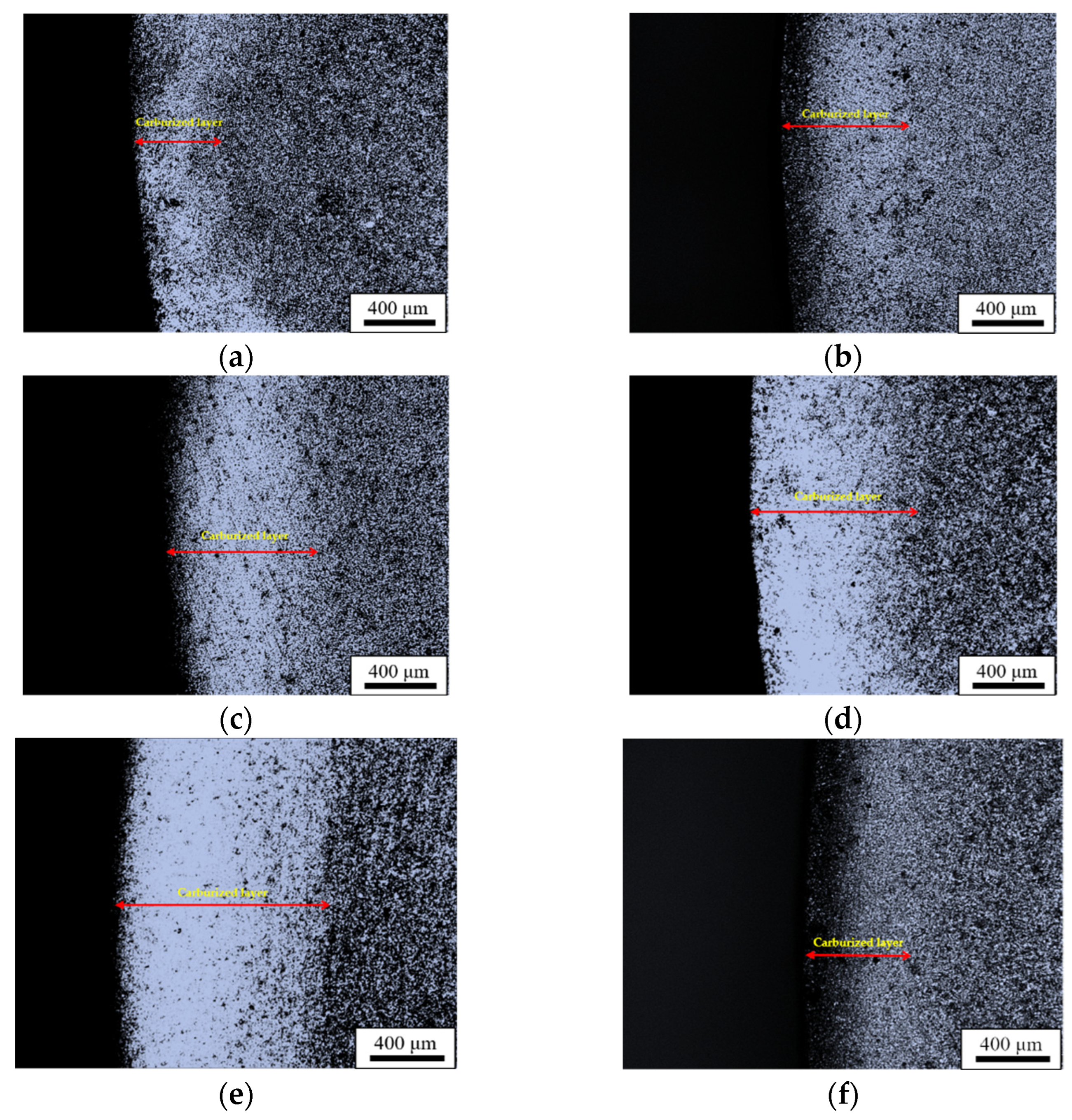
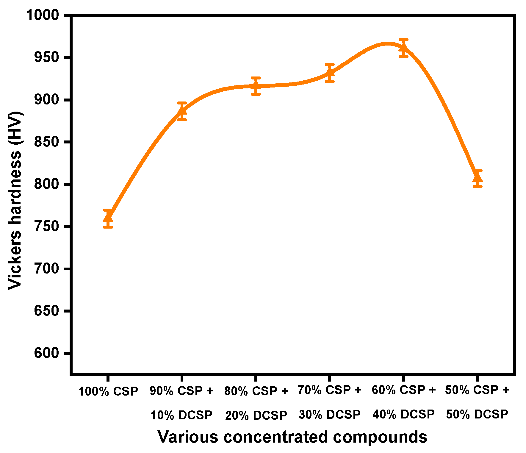
3.1. Effective Case Depth of Quenched Specimens with Different Percentages of Carburizing Media and Carburization Times

Figure 1a–f shows the microhardness profile of quenched specimens during carburization using various CSP–DCSP ratios of 100%:0%, 90%:10%, 80%:20%, 70%:30%, 60%:40%, and 50%:50% for 3, 6, and 12 h, respectively. As illustrated in Figure 1, the microhardness value of all quenched specimens prepared with various CSP–DCSP ratios and carburizing times decreases linearly as the depth from the surface to the substrate increases. Since the surface’s carburizing condition almost remains the same as the fixed carbon content depending on the powders’ ratio, the carbon contribution profiles gradually decrease from the surface. According to Frick’s first law of diffusion, the surface’s microhardness and carbon content show an almost linearly decreased phenomenon. This pattern also matches the microhardness profile obtained by Li et al. on carburized 20CrNi2MoV steel specimens [34].
Figure 1a shows the microhardness profile of quenched specimens using CSP–DCSP ratio of 100%:0% for carburizing times of 3, 6, and 12 h. The surface microhardness measurements of 628.5 ± 5.385 HV, 667.3 ± 5.032 HV, and 759.4 ± 5.169 HV were obtained after 3, 6, and 12 h, respectively. The hardness gradually decreased to 550 HV with a slight fluctuation in the range of 460 µm toward the core area for 3 h, 650 µm for 6 h, and 910 µm for 12 h carburization times. This result indicated that the effective case depth of 460 µm is achieved after 3 h of carburization. After extending the carburizing duration to 6 and 12 h, the effective case depth rose to 650 µm and 910 µm, respectively. Figure 1b shows the microhardness profile obtained after 3, 6, and 12 h of carburization with a CSP-DCSP ratio of 90%:10%. From the microhardness measurement results, the effective case depth of 520 µm was obtained after 3 h. After 6 and 12 h of carburization, the effective case depth increased to 770 µm and 1120 µm, respectively. The effective case depths of 620 µm, 890 µm, and 1420 µm were obtained through carburization with an 80%:20% ratio of CSP–DCSP for 3, 6, and 12 h as shown in Figure 1c. After the carburizing process for 3, 6, and 12 h using a CSP–DCSP ratio of 70%:30%, the effective case depth of quenched specimens increased to 840 µm, 1050 µm, and 1840 µm, respectively as depicted in Figure 1d. Furthermore, Figure 1e shows that after increasing the DCSP concentrations to 40% (i.e., CSP–DCSP ratio of 60%:40%) for carburizing times of 3, 6, and 12 h, the effective case depth increased to 920 µm, 1420 µm, and 2340 µm, respectively. However, after adding DCSP concentrations of 50% on the carburizing process for 3, 6, and 12 h, the effective case depth decreases to 640 µm, 705 µm, and 1010 µm, respectively. From Figure 1, it is found that as the time for pack carburization increases, the effective case depth increases as well. Additionally, the effective case depth increases when DCSP concentrations increase from 0% to 40% and decreases when DCSP concentrations increase further to 50%. It can be seen that, in all various times of carburization (i.e., 3, 6, and 12 h), carburization using DCSP of 40% achieved a higher effective case depth than other DCSP concentrations (i.e., 0%, 10%, 20%, 30%, and 50%). These results are related to the depth of carburized layer for a CSP–DCSP ratio of 60%:40%, higher than other CSP–DCSP ratios. The OM images of carburized layer thickness for quenched specimens using CSP–DCSP ratios of 100%:0%, 90%:10%, 80%:20%, 70%:30%, 60%:40%, and 50%:50% with carburizing times of 12 h are presented in Figure 2a–f. The results confirm that the thickness of carburized layer increases by increasing the DCSP concentrations to 40% and decreases by increasing the DCSP concentrations to 50%.
Interestingly, the maximum effective case depth value presented in Figure 1e (2340 µm) is around 1.6 times greater than the value obtained in a previous study of alloy steel vacuum carburization using Y ion implantation (1.47 mm) at a temperature of 920 °C for 5 h [35]. Moreover, it is approximately 3.1 times higher than that achieved in a previous study using a combination of arecaceae flower waste and eggshells as a carburizing media in the carburization of mild steel (0.75 mm) at a temperature of 920 °C for 5 h [14]. However, the maximum effective case depth value obtained in this study is still lower than the maximum value obtained in another previous study using carburizing compositions of charcoal and cowbone (2.6 mm) in RST 37 grade steel carburization [1].

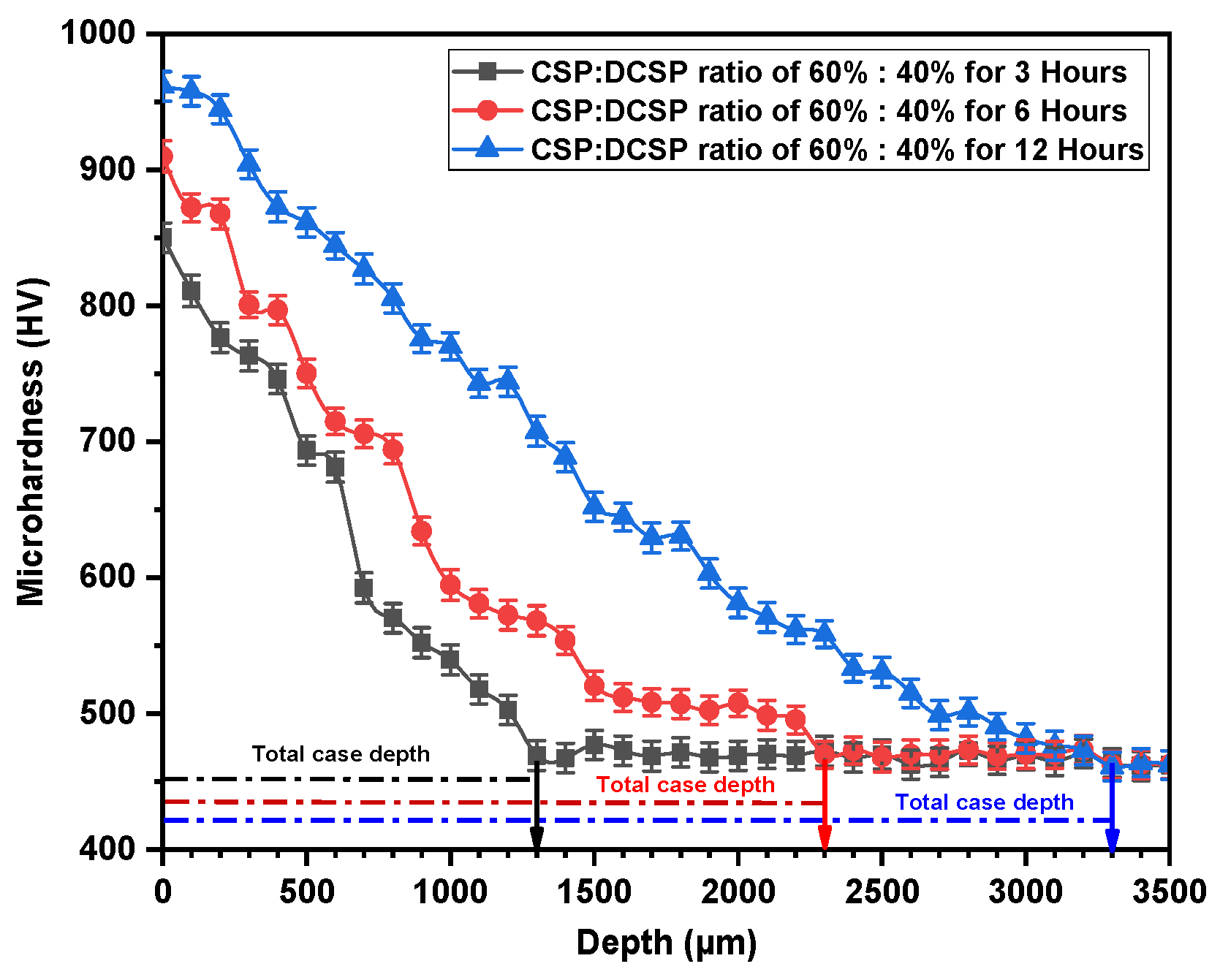
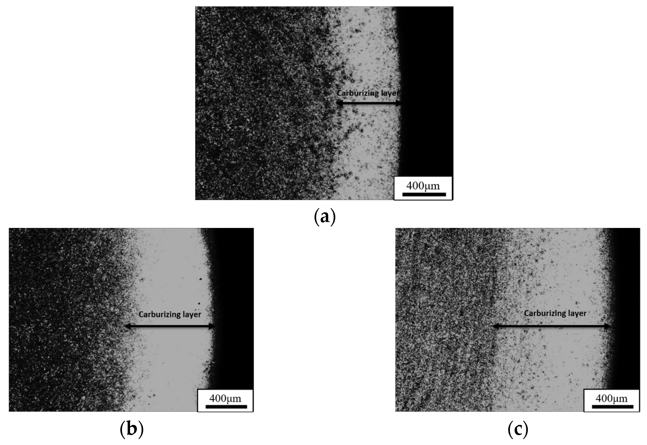
3.2. Total Case Depth of Quenched Specimens Prepared with CSP–DCSP Ratio of 60%:40% and Carburizing Times of 3, 6, and 12 h

Figure 3 shows the microhardness profile and the carburized layer thickness of the SCM 420 steel during carburization with a CSP–DCSP ratio of 60%:40% for 3, 6, and 12 h. The total case depth measurements were performed by observing and measuring the distances between the highest hardness value on the surface of each sample and the point at which the hardness value begins to stabilize toward the core area. From the measurement results, the total case depth of 1300 µm was obtained after 3 h of carburization. After 6 h of carburization, the total case depth increases to 2300 µm. Moreover, after extending the carburizing time to 12 h, the total case depth increases significantly to 3300 µm. The OM images of carburized layer prepared using a CSP–DCSP ratio of 60%:40% with carburizing times of 3, 6, and 12 h are shown in Figure 4a–c. The results confirmed that as the carburizing time increases, the depth of the carburized layer increases as well.

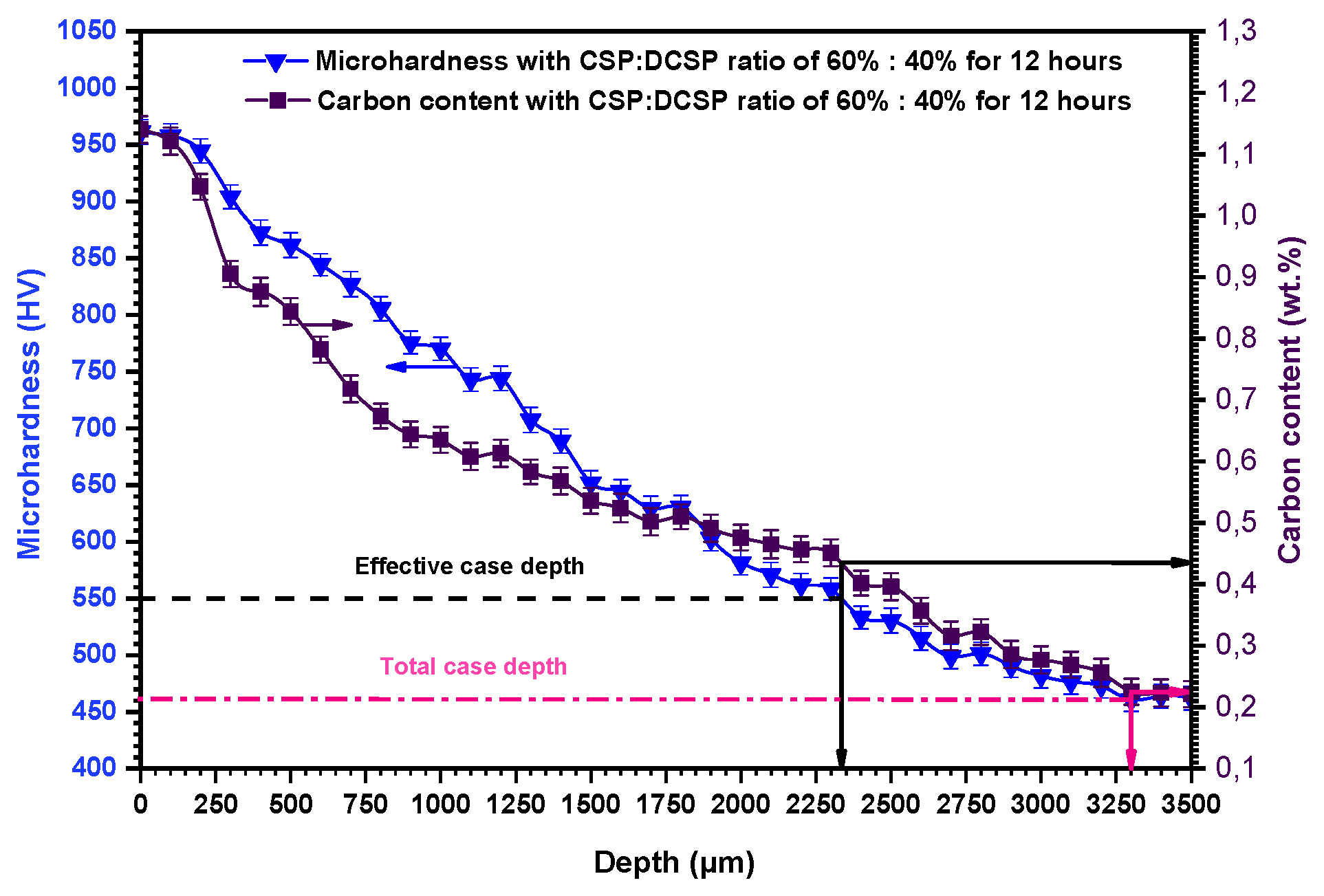
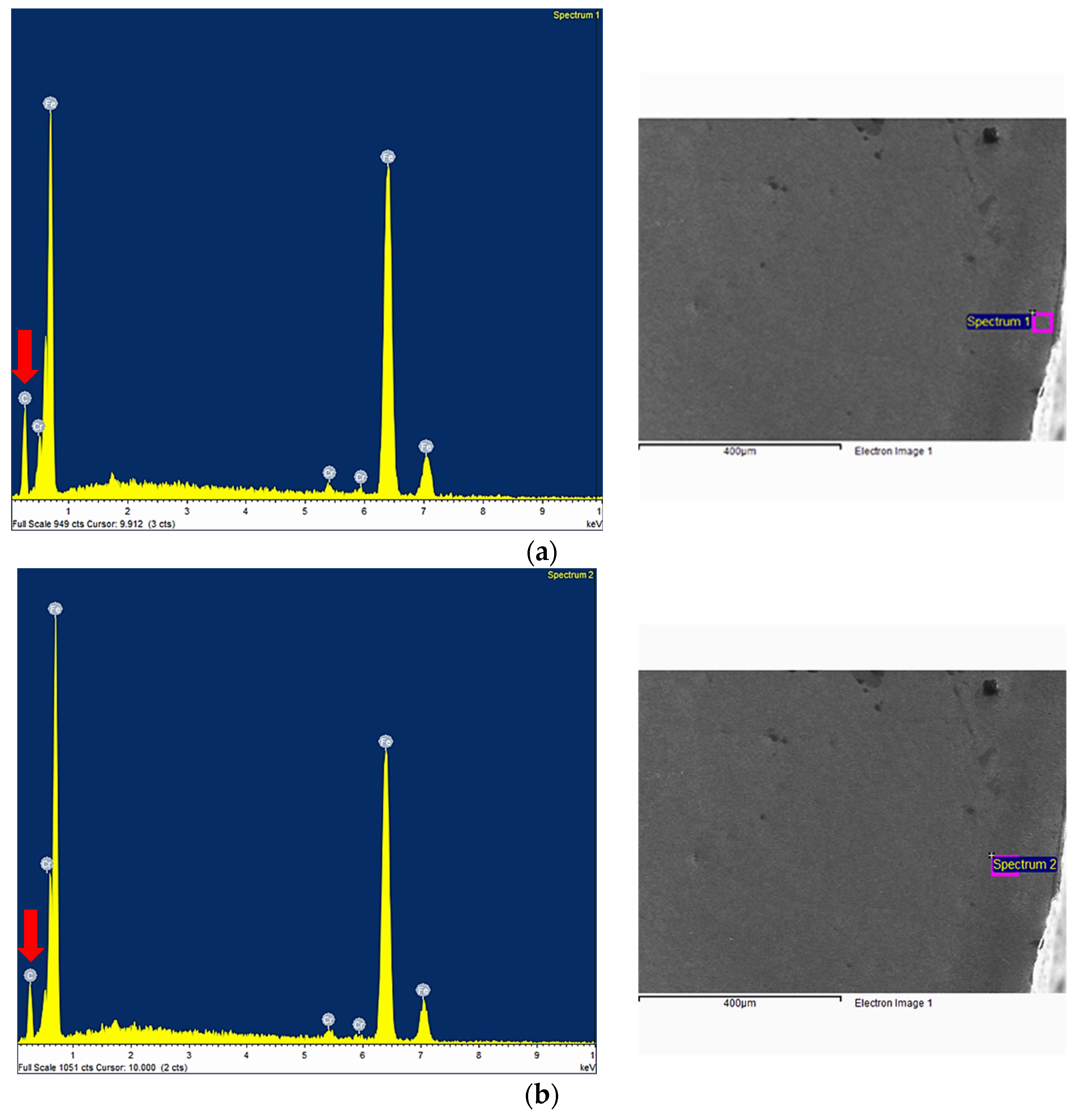
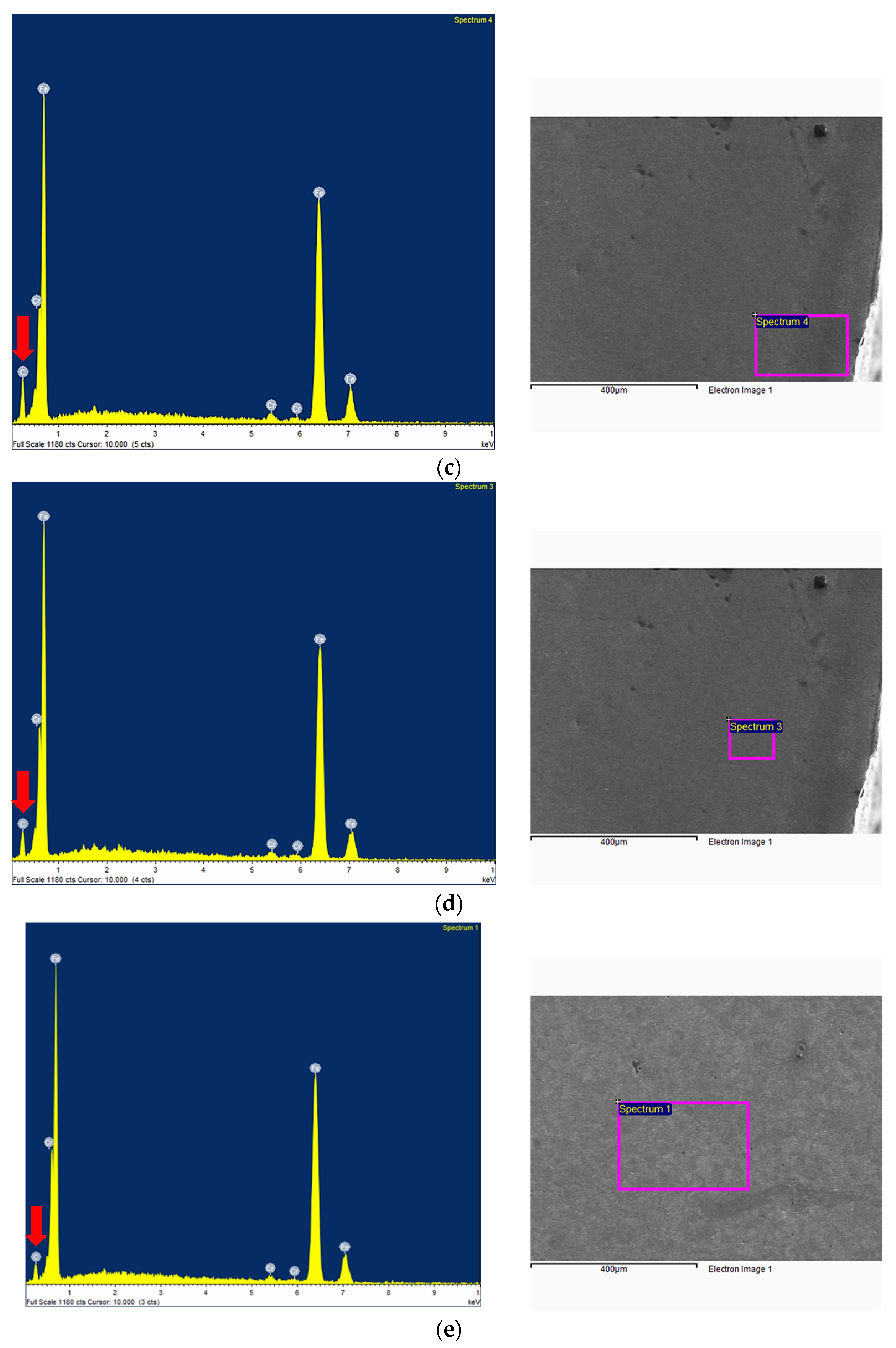
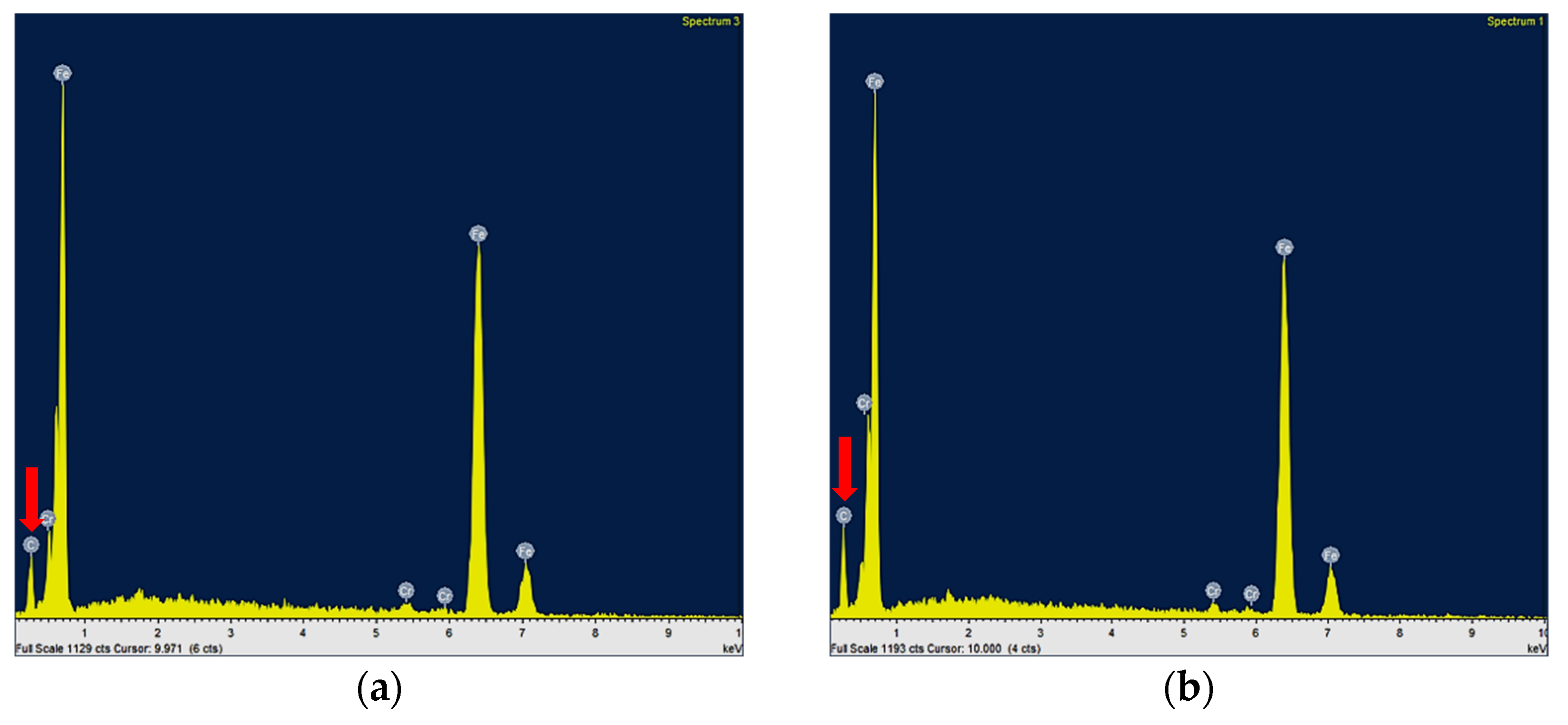
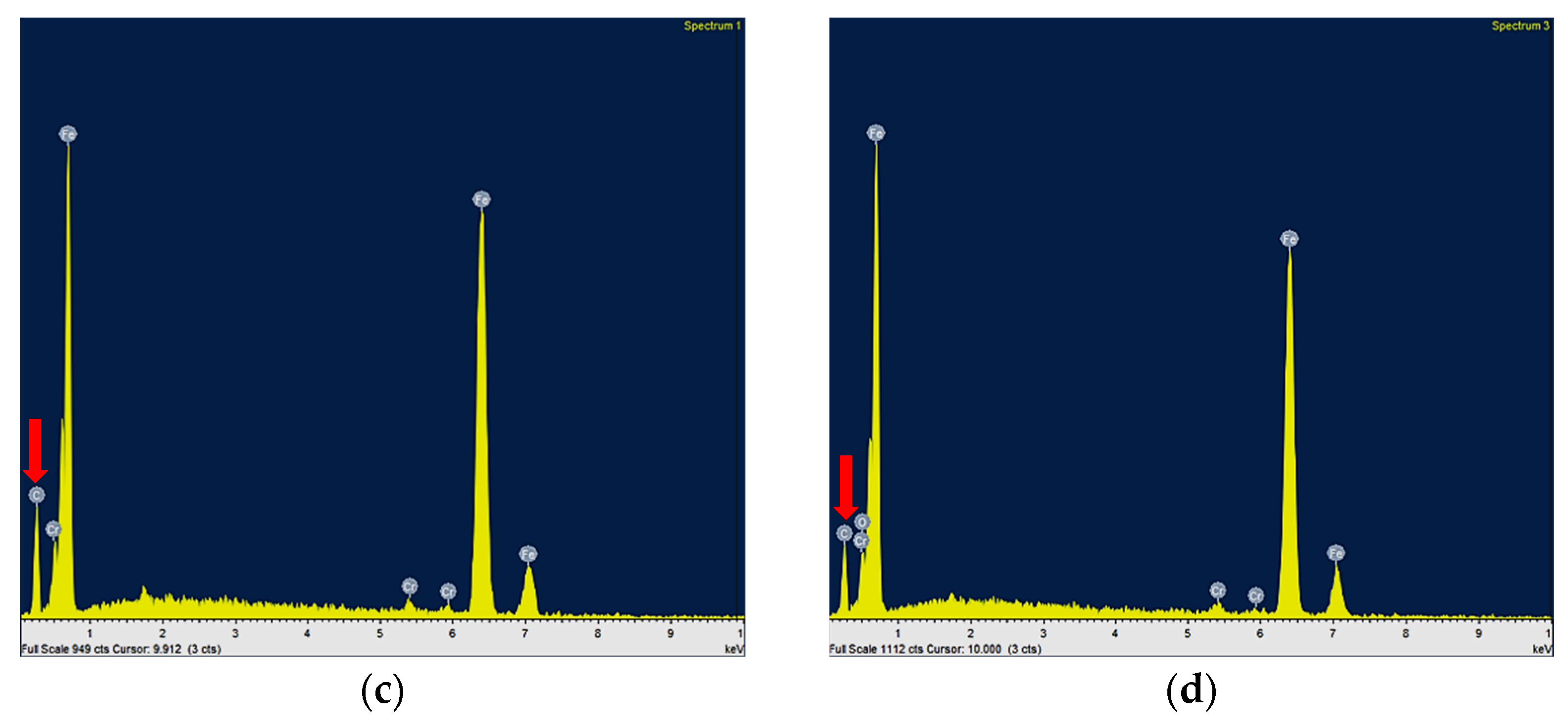
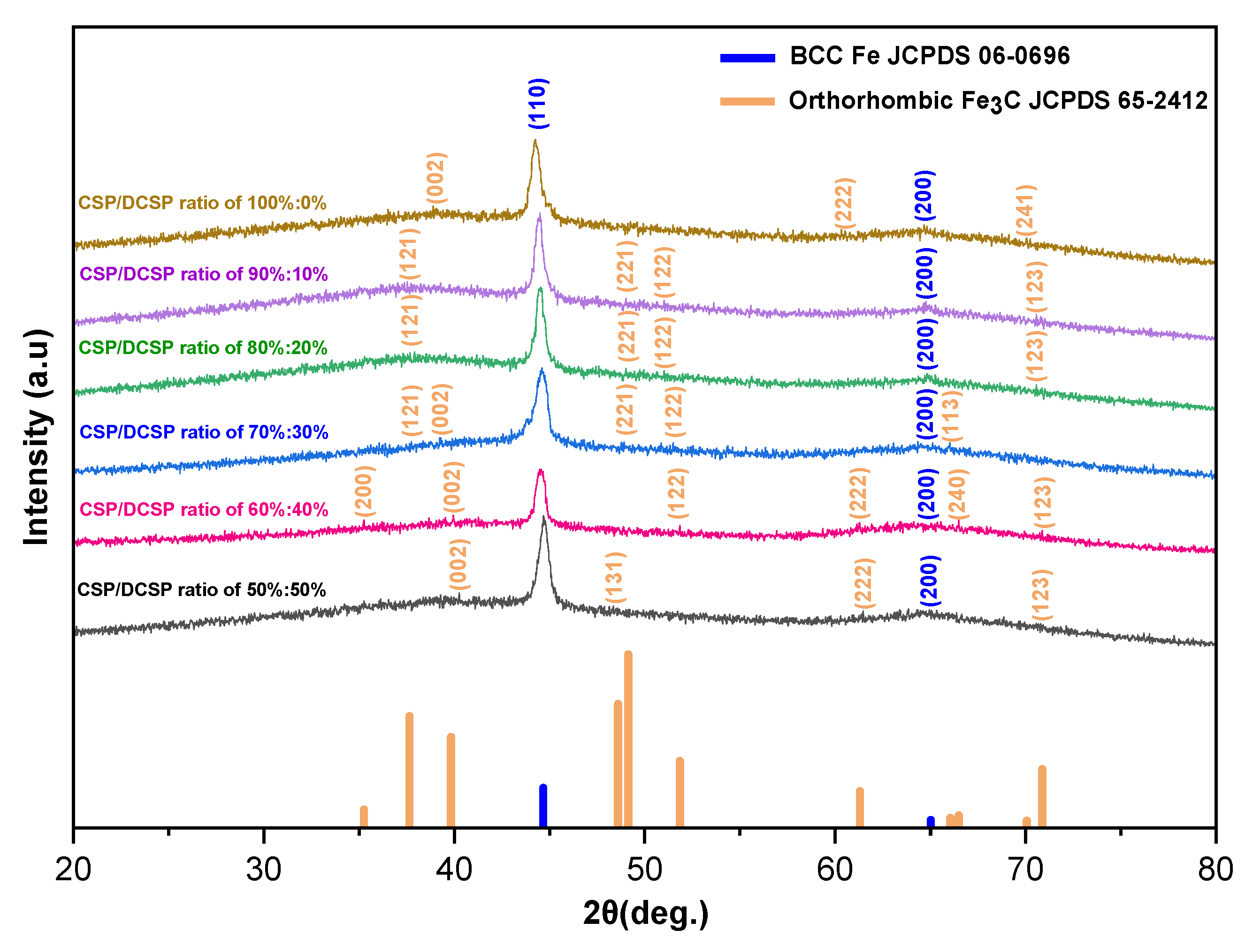
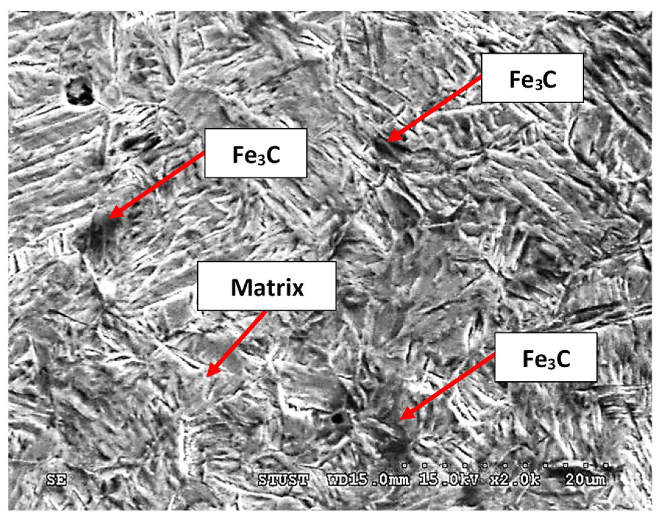
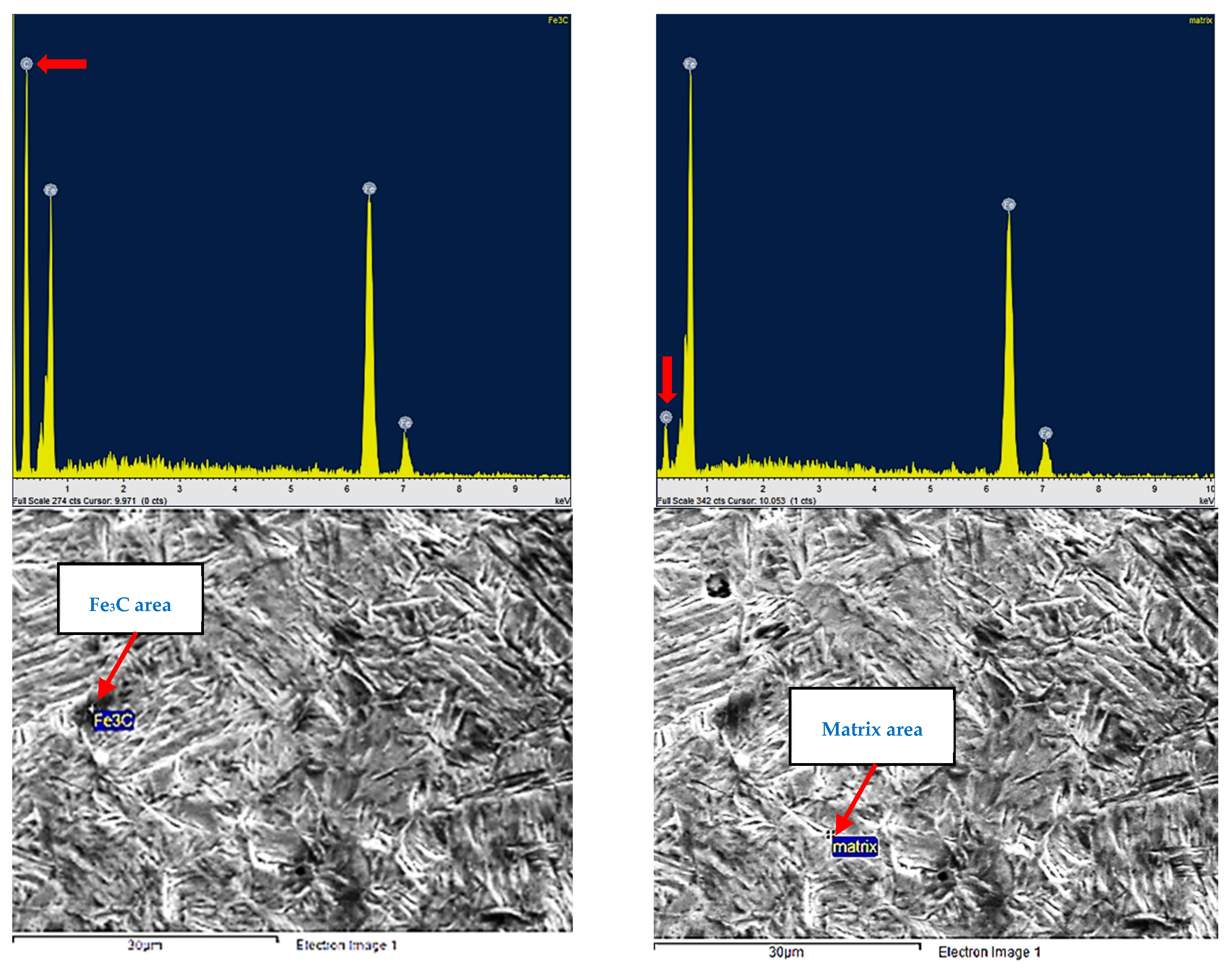
3.3. Carbon Content Distribution on the Effective Case Depth and Total Case Depth of Quenched Specimen with a Carburizing Time of 12 h and CSP–DCSP Ratio of 60%:40%

Figure 5 shows the carbon content distribution on the microhardness value of the carburized layer during carburization with a carburizing time of 12 h and a CSP–DCSP ratio of 60%:40% as a carburizing media. It is seen that the carbon content on the sample’s surface of 1.14 ± 0.007 wt.% gradually decreases approximately to 0.435 wt.% at the distance of 2340 µm toward the core area. This result indicated that the minimum carbon content required for effective case depth formation of SCM 420 steel carburized samples during carburization with a CSP–DCSP ratio of 60%:40% as a carburizing media and carburizing time of 12 h is around 0.435 wt.%. Furthermore, the carbon content gradually decreases to approximately 0.225 ± 0.006 wt.% at a distance of 3300 µm toward the core area, showing that the minimum carbon content on the total case depth is around 0.225 wt.%.
Figure 6 shows the XRD results of quenched specimens prepared with a CSP–DCSP ratio of 60%:40% and carburizing time of 12 h on different thickness layers. It was found that the intensity of the iron (Fe) in the surface layer was lower than that found in the layers with a depth of 300 µm, 600 µm, and 900 µm from the surface, and in the core area, respectively. Furthermore, the quantity of Fe3C contained in the surface area was more than that found in layers with a depth of 300 µm, 600 µm, and 900 µm, and in the core area. These results indicate that the intensity of carbon contained in the surface layer is also higher than that obtained in the other layers. The EDS analysis results of SCM 420 quenched specimens prepared with DCSP concentrations of 40% for a carburizing time of 12 h in different depth layers are presented in Figure 7. From Figure 7, it is found that the carbon intensity on the surface (a) is higher than that obtained at the depths of 300 µm (b), 600 µm (c), and 900 µm (d), and the core area (e), respectively. The EDS analysis results confirmed that the carbon intensity of quenched specimens gradually decreased from the surface layer to the substrate. Due to the decreased quantity of Fe3C and carbon intensity from the surface layer to the core, the hardness value gradually decreases from the surface layer to the core area, as illustrated in Figure 1e.

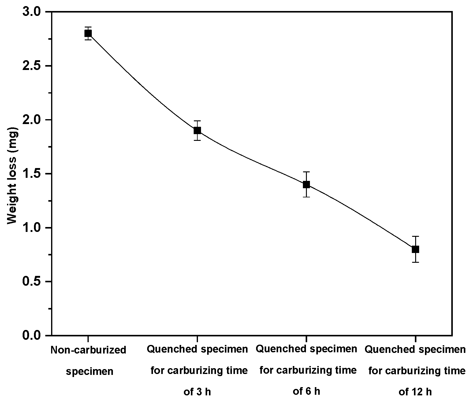
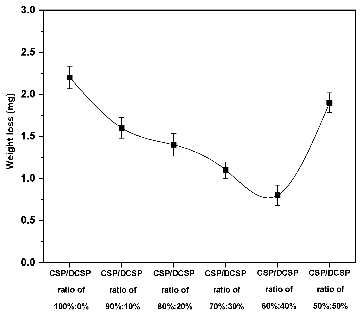
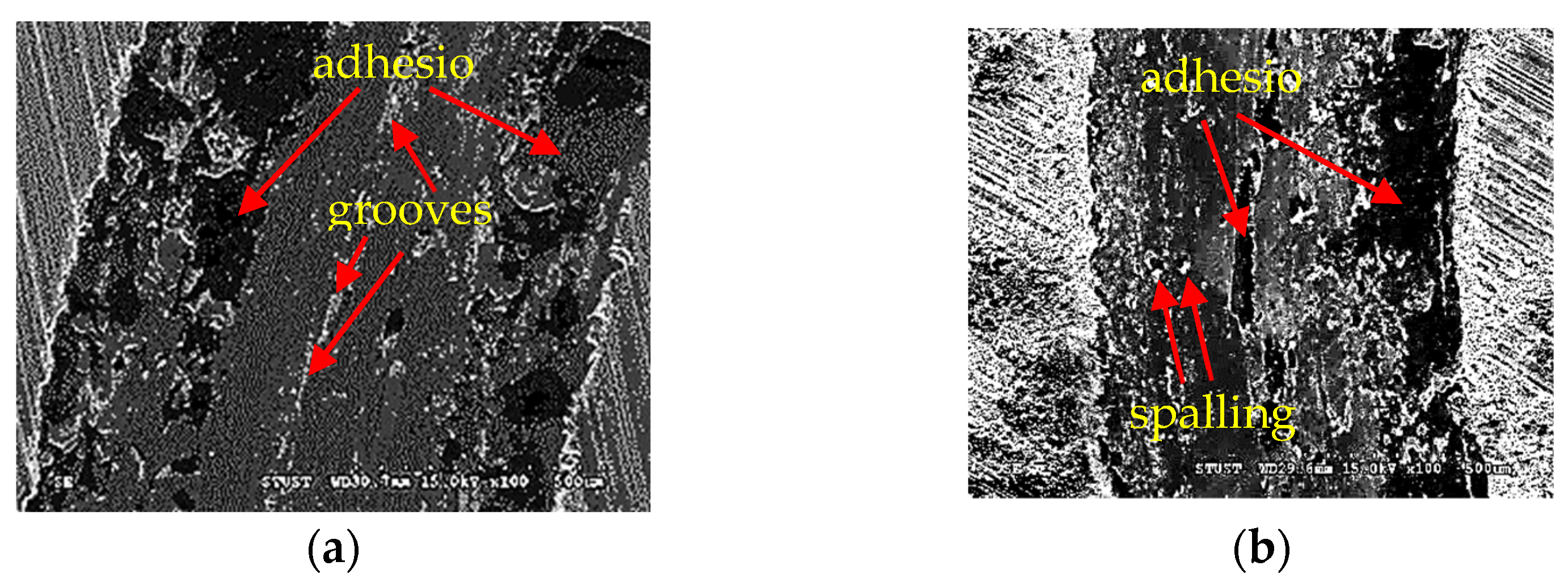
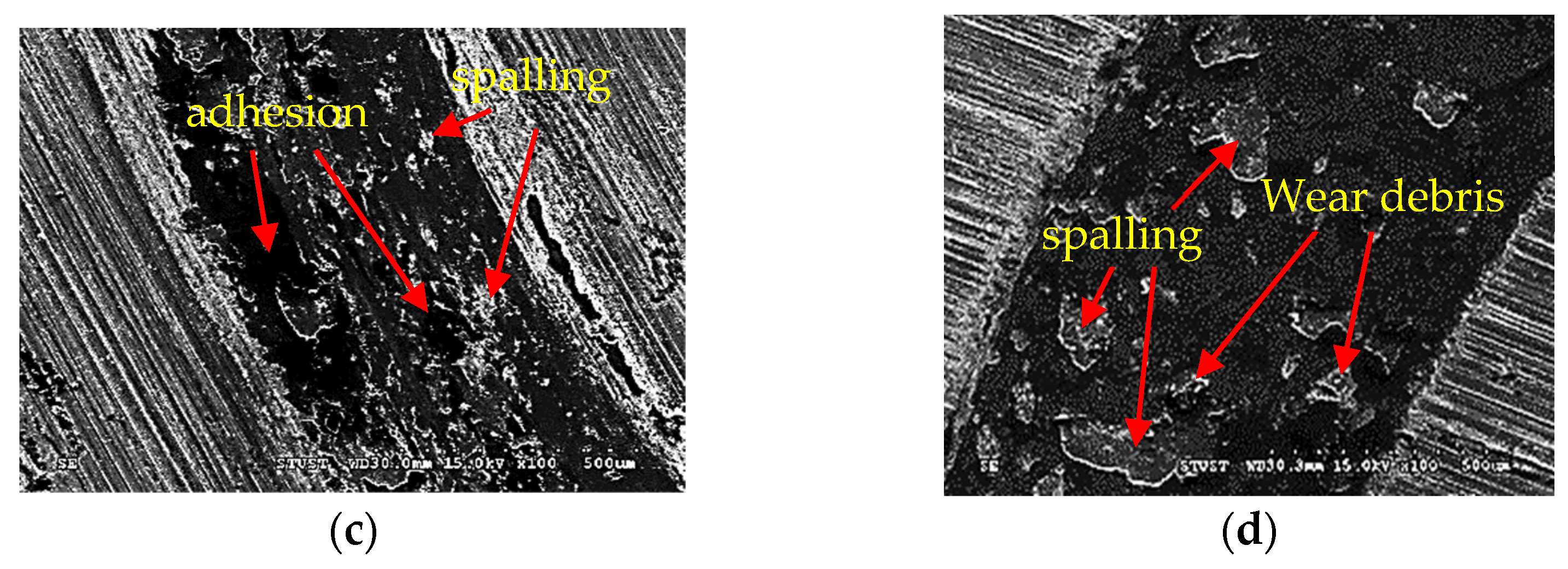
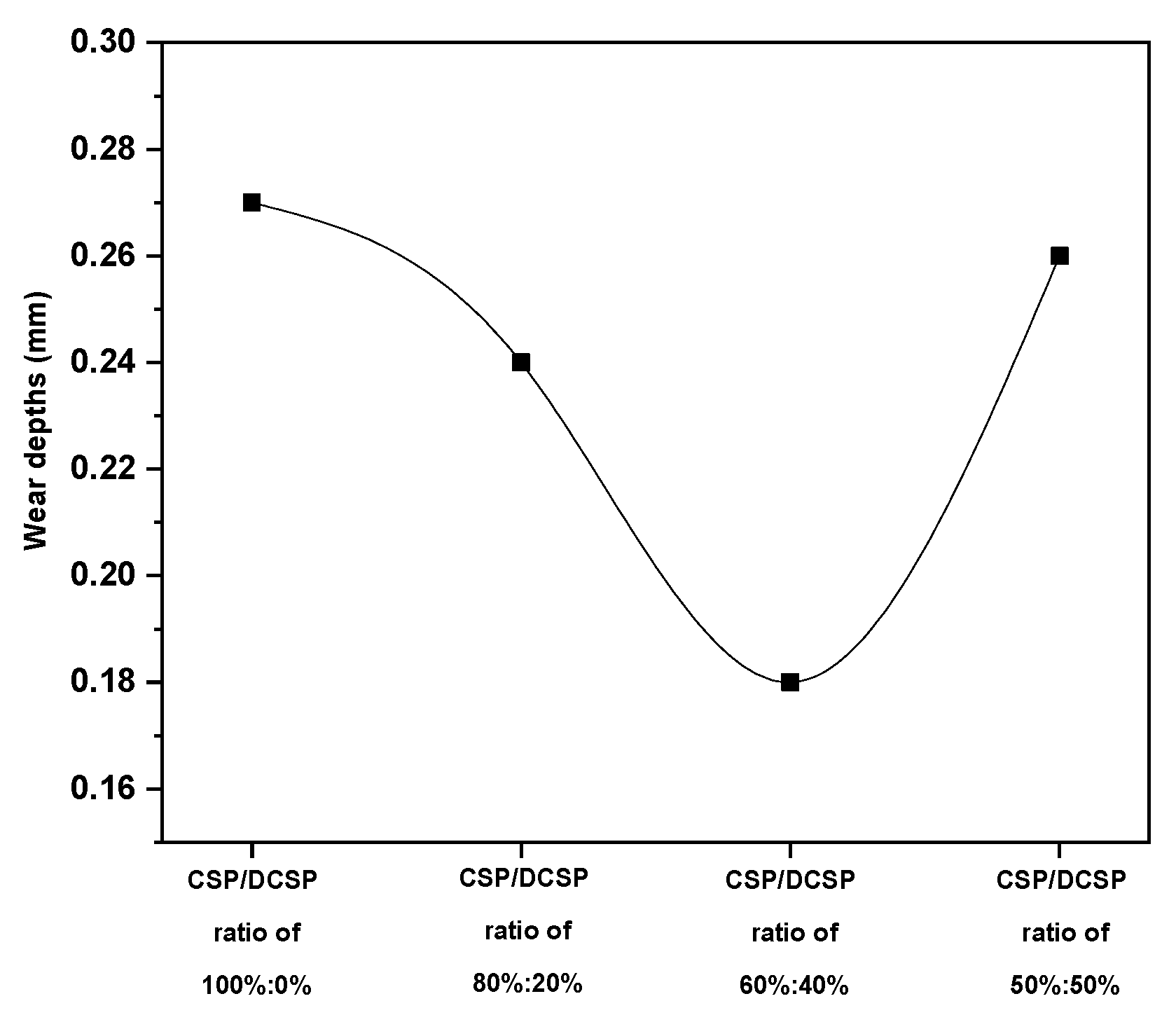
3.4. Wear Resistance of Quenched Specimens

The weight loss of quenched specimens prepared with a CSP–DCSP ratio of 60%:40% for carburizing times of 3, 6, and 12 h are shown in Figure 8. It was found that the weight loss value was 2.8 ± 0.089 mg for untreated specimens. After the carburizing process for 3, 6, and 12 h, the weight loss value decreased to 1.9 ± 0.141 mg, 1.4 ± 0.167 mg, and 0.8 ± 0.170 mg, respectively. These results indicate that after the carburizing process using a DCSP concentration of 40% as a carburizing media with a carburization time of 12 h, the wear resistance of the quenched specimen increased around 3.5 times compared to untreated specimens [29]. The wear test results of the quenched specimens prepared with various CSP–DCSP ratios of 100%:0%, 90%:10%, 80%:20%, 70%:30%, 60%:40%, and 50%:50% for a carburizing time of 12 h are shown in Figure 9. The results show the weight loss value of 2.2 ± 0.185 mg for quenched specimens prepared with a CSP–DCSP ratio of 100%:0%. After increasing the DCSP concentrations to 10%, 20%, 30%, and 40%, the weight loss value decreased to 1.6 ± 0.172 mg, 1.4 ± 0.185 mg, 1.1 ± 0.148 mg, and 0.8 ± 0.170 mg, respectively, and further increased to 1.9 ± 0.167 mg when the DCSP concentration increased to 50%. The volume loss of the wear specimen decreased from 0.28 mm3 to 0.1 mm3 after increasing the DCSP concentrations from 0% to 40%. These results indicate that the wear resistance of quenched specimens increased around 2.75 times by adding the DCSP concentrations from 0% to 40%. However, the wear resistance decreased by further adding the DCSP concentrations from 40% to 50%.
The wear resistance results of quenched specimens prepared with various CSP–DCSP ratios of 100%:0%, 90%:10%, 80%:20%, 70%:30%, 60%:40%, and 50%:50% related to the surface hardness value of each sample. The surface hardness values of quenched specimens were increased by increasing the DCSP concentrations from 0% to 40%, and decreased when increasing the DCSP concentration to 50% after a carburization time of 12 h as depicted in Figure 10 [29].
Figure 11 shows the EDS analysis results of quenched specimens prepared with various DCSP concentrations of 0% (a), 20% (b), 40% (c), and 50% (d) after 12 h carburization. It was found that the carbon intensity on the carburized layer of quenched specimens increased after increasing DCSP concentrations from 0% to 20% and from 20% to 40%. However, the intensity of carbon decreased after increasing DCSP concentrations from 40% to 50%. Similarly, as shown in Figure 12, the number of martensite structures in quenched specimens increased as DCSP concentrations increased from 0% to 40% and decreased as DCSP concentrations increased to 50%. As a result, when DCSP concentrations were increased from 0% to 40% as a carburizing media, the hardness value and wear resistance of quenched specimens increased and decreased when further increased to 50%.
Figure 13 shows XRD analysis results of quenched specimen carburized using CSP–DCSP ratios of 100%:0%, 90%:10%, 80%:20%, 70%:30%, 60%:40%, and 50%:50% with a carburizing time of 12 h. It is worthwhile to note the XRD profile taken from the 50%:50% specimen. The 2θ diffraction angles of the (110) plane were shifted to a higher value, indicating that the lattice constant of the BCC Fe was smaller than other specimens under different CSP–DCSP ratios. It is reasonable to deduce that the carbon atom concentration of BCC Fe in the 50%:50% specimen is relatively low, indicating that the effect of carburization is not promoted as expected. This experimental result is consistent with the microhardness and the wear property. Based on the surface microhardness property in Figure 10 and the weight loss property in Figure 9, the surface hardness of the 50%:50% specimen is the lowest among those specimens with different CSP–DCSP ratios (i.e., DCSP concentrations of 10% to 40%). Abrasion data also show that the 50%:50% specimen has the greatest weight loss.
The presence of Fe3C on the quenched specimens was also observed by SEM and EDS, as depicted in Figure 14 and Figure 15. From Figure 14, it was found that some iron carbide (Fe3C) existed on the carburized layer of quenched specimens. Furthermore, from Figure 15, EDS analysis results show that certain particles are enriched in carbon elements, indicating that these particles were Fe3C carbides. This result was consistent with the XRD analysis results presented in Figure 6 and Figure 13.
Furthermore, the elements distributed on the Fe3C and the matrix from EDS analysis results are shown in Table 2 and Table 3, respectively. Generally, the EDS analysis results cannot present the exact weight and atomic percentages of light elements such as carbon. However, from Table 2 and Table 3, it can be observed that the carbon elements on the Fe3C area are much higher than presented in the matrix area. Again, these results also confirm that the iron carbide exists on the quenched specimens prepared using a CSP–DCSP ratio of 60%:40% and a carburizing time of 12 h.
The worn surface of the samples was examined by scanning electron microscopes. SEM micrographs of the worn surfaces of quenched specimens prepared with CSP–DCSP ratios of 100%:0%, 80%:20%, 60%:40%, and 50%:50% for a carburizing time of 12 h are shown in Figure 16. Figure 16a,d show the wear widths of 1.05 mm and 0.9 mm for the specimens prepared with CSP–DCSP ratios of 100%:0% and 50%:50%, respectively, for a carburizing time of 12 h after a sliding distance of 200 m at 20 N. These are much larger than the wear widths obtained on the specimens prepared with CSP–DCSP ratios of 80%:20% and 60%:40% of 0.75 mm and 0.55 mm as shown in Figure 16b,c, respectively. The above results confirm that the wear weight losses of specimens with CSP–DCSP ratios of 100%:0% and 50%:50% at the carburizing time of 12 h are greater than those of specimens with 80%:20% and 60%:40% for a carburizing time of 12 h. Since the wear width of the specimen in Figure 16 was determined from surface morphology by converting the mass loss to volume loss using the appropriate density of material specimens, the wear depths of specimens can be estimated. Volume losses are 0.28 mm3, 0.18 mm3, 0.1 mm3, and 0.24 mm3 for quenched specimens prepared with DCSP concentrations of 0%, 20%, 40%, and 50%, respectively. The wear depths of quenched specimens prepared with CSP–DCSP ratios of 100%:0%, 80%:20%, 60%:40%, and 50%:50% are presented in Figure 17. From Figure 17, it is found that the wear depths of quenched specimens prepared with CSP–DCSP ratios of 100%:0%, 80%:20%, 60%:40%, and 50%:50% are 0.27 mm, 0.24 mm, 0.18 mm, and 0.26 mm, respectively. From the above results, it can be stated that the mass loss, volume loss, and wear depth of specimens with CSP–DCSP concentrations of 100%:0% and 50%:50% are higher than those obtained on the specimens prepared with CSP–DCSP ratios of 80%:20% and 60%:40%. These results confirmed that the wear resistance of quenched specimens prepared with a CSP–DCSP ratio of 80%:20% and a CSP–DCSP ratio of 60%:40% (Figure 16b,c, respectively) is higher than the wear resistance of specimens with CSP–DCSP ratios of 100%:0% and 50%:50%, as shown in Figure 16a,d, respectively.
In addition, from the observation results of the worn surface morphology of each test specimen, it can be found that the main wear mechanisms of the carburized layer are adhesion, wear debris, spalling, and grooves [36,37]. It is worth noting that the wear surface morphology of the carburized layer of the specimens with a CSP–DCSP ratio of 50%:50% for the carburizing time of 12 h shows more serious spalling and more wear debris, as shown in Figure 16d. On the other hand, the worn surface morphology of the carburized layer of the specimens prepared with a CSP–DCSP ratio of 100%:0% for a carburizing time of 12 h showed severe adhesive wear and grooves, as shown in Figure 16a. Based on the abovementioned research results, it can be seen that the hardness value of the specimens prepared with a CSP–DCSP ratio of 100%:0% and a CSP–DCSP ratio of 50%:50% for a carburizing time of 12 h are lower than the hardness value of the specimens prepared with a CSP–DCSP ratio of 80%:20% and a CSP–DCSP ratio of 60%:40%. Moreover, the wear weight loss of the quenched specimens carburized using a CSP–DCSP ratio of 100%:0% and a CSP–DCSP ratio of 50%:50% with a carburizing time of 12 h was also greater than the quenched specimens carburized using CSP–DCSP ratios of 80%:20% and 60%:40%. Therefore, the specimens with a CSP–DCSP ratio of 100%:0% and a CSP–DCSP ratio of 50%:50% with a carburizing time of 12 h exhibit poor wear resistance. The greater wear weight loss and the poorer wear resistance may be related to the hardness and the density of the microstructure of the carburized layer.

4. Conclusions

The efficacy of natural shell waste powders (i.e., coconut shell powder and dog conch shell powder) as an alternative carburizing media on the pack carburization of SCM 420 steel for various carburizing times and carburizing media concentrations at a temperature of 950 °C has been investigated and confirmed. The investigation concentrated on the effects of the various CSP–DCSP ratios (100%:0%, 90%:10%, 80%:20%, 70%:30%, 60%:40%, and 50%:50%) and the carburization times (3, 6, and 12 h) on effective case depth and wear resistance of the samples. Based on the experimental results, the following conclusions can be drawn:
  • The effective case depth, total case depth, and wear resistance increased by increasing the carburizing times.
  • The highest effective case depth, total case depth, and wear resistance were attained using a CSP–DCSP ratio of 60:40% as a carburizing media for all various carburization times (i.e., 3, 6, and 12 h).
  • The effective case depth value of quenched specimens for a carburizing time of 12 h increased approximately 2.57 times when increasing DCSP concentrations from 0% to 40% and decreased when further increasing DCSP concentrations from 40% to 50%.
  • Based on the mass loss results, the wear resistance of quenched specimens with 12 h carburization increased around 2.75 times when increasing DCSP concentration from 0% to 40% and decreased when increasing DCSP concentration to 50%.
  • The wear depths of quenched specimens with 12 h carburization also increased around 1.5 times after increasing DCSP concentration from 0% to 40%.
  • Similarly, EDS analysis results showed that the carbon intensity of the specimens increased after increasing DCSP concentrations from 0% to 40%, and decreased after increasing DCSP percentages from 40% to 50%.
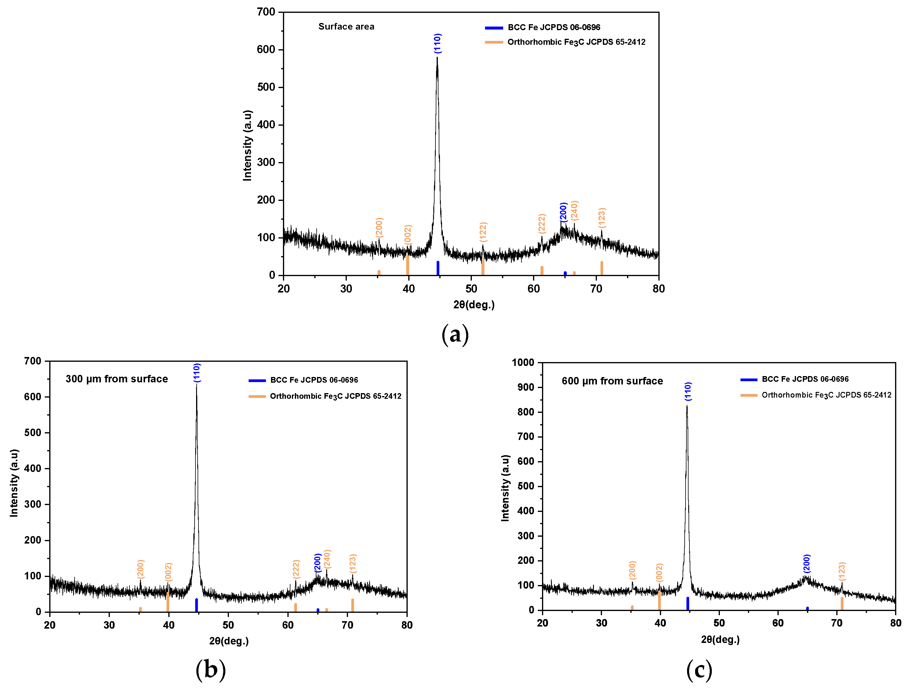
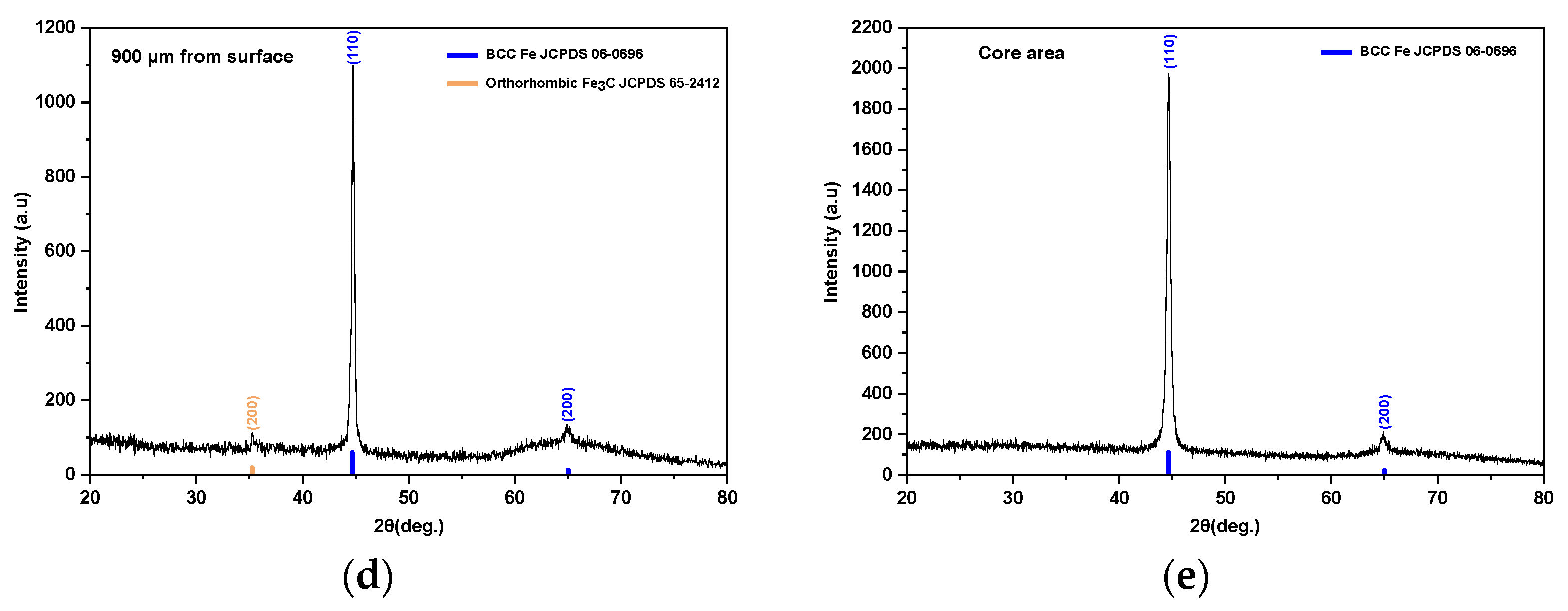
  • The EDS analysis results showed that the carbon intensity of SCM 420 quenched specimens gradually decreased from the surface to the substrate.
  • The minimum carbon content required for effective case depth formation of SCM 420 steel carburized specimens by using a CSP–DCSP ratio of 60%:40% as a carburizing media and a carburizing time of 12 h is around 0.435 wt.%.
The effect of effective case depth value on the fatigue resistance of SCM 420 carburized specimens will be investigated in a future study to complete the mechanical properties investigation.

Author Contributions

Conceptualization, R. and C.-C.W.; methodology, R. and C.-C.W.; software, R.; formal analysis, R. and C.-C.W.; investigation, R. and C.-C.W.; data curation, R. and C.-C.W.; writing—original draft preparation, R.; writing—review and editing, R. and C.-C.W.; visualization, R. and C.-C.W. All authors have read and agreed to the published version of the manuscript.

Funding

This research was funded by the Ministry of Science and Technology, Taiwan, R.O.C, under grant No. MOST 110-2622-E-218-002.

Institutional Review Board Statement

Not applicable.

Informed Consent Statement

Not applicable.

Data Availability Statement

Not applicable.

Conflicts of Interest

The authors declare no conflict of interest.

References

  1. Asuquo, L.O.; Ihom, A.P. Variation of Effective Case Depth with Holding Time of Mild Steel Using Various Carburising Compounds. Int. J. Met. Steel Res. Technol. 2013, 1, 12–18. [Google Scholar]
  2. Kong, J.H.; Okumiya, M.; Tsunekawa, Y.; Takeda, T.; Yun, K.Y.; Yoshida, M.; Kim, S.G. Surface Modification of SCM420 Steel by Plasma Electrolytic Treatment. Surf. Coat. Technol. 2013, 232, 275–282. [Google Scholar] [CrossRef]
  3. Kazuaki, F.; Kunikazu, T.; Tetsuo, S. Examination of Surface Hardening Process for Dual Phase Steel and Improvement of Gear Properties. JFE GIHO 2009, 23, 24–29. [Google Scholar]
  4. Jeong, Y.E.; Lee, J.Y.; Lee, E.K.; Shim, D.S. Microstructures and Mechanical Properties of Deposited Fe-8Cr-3V-2Mo-2W on SCM420 Substrate Using Directed Energy Deposition and Effect of Post-Heat Treatment. Materials 2021, 14, 1231. [Google Scholar] [CrossRef] [PubMed]
  5. Natpukkana, P.; Pakinsee, S.; Boonmapat, S.; Mitsomwang, P.; Borrisutthekul, R.; Panuwannakorn, R.; Khoa-phong, L. Investigation of Notch Shear Cutting for JIS SCM420 Steel Wire Rod. IOP Conf. Ser. Mater. Sci. Eng. 2018, 436, 012013. [Google Scholar] [CrossRef]
  6. Akhtar Raja, M.; Raj Mishra, M. A Study of Optimization and Improvement of Mechanical Properties of Low Carbon Steel by the Process of Carburization. Int. J. Eng. Tech. Res. IJETR 2019, 9, 11–13. [Google Scholar] [CrossRef]
  7. Prime, M.B.; Prantil, V.C.; Rangaswamy, P.; García, F.P. Residual Stress Measurement and Prediction in a Hardened Steel Ring. Mater. Sci. Forum 2000, 347–349, 223–228. [Google Scholar] [CrossRef]
  8. Oyetunji, A.; Adeosun, S.O. Effects of Carburizing Process Variables on Mechanical and Chemical Properties of Carburized Mild Steel. J. Basic Appl. Sci. 2012, 8, 319–324. [Google Scholar] [CrossRef]
  9. Levitas, V.I.; Roy, A.M. Multiphase Phase Field Theory for Temperature- and Stress-Induced Phase Transformations. Phys. Rev. B 2015, 91, 174109. [Google Scholar] [CrossRef] [Green Version]
  10. Levitas, V.I.; Roy, A.M.; Preston, D.L. Multiple Twinning and Variant-Variant Transformations in Martensite: Phase-Field Approach. Phys. Rev. B 2013, 88, 054113. [Google Scholar] [CrossRef] [Green Version]
  11. Benarioua, Y. Effect of Temperature and Time of Carburizing Treatment on the Structure and the Hardness of Steel 20MC4. Int. J. Sustain. Water Environ. Syst. 2016, 8, 3–6. [Google Scholar] [CrossRef]
  12. Madu, K.; Uyaelumuo, A.E. Parametric Effects of Carburization Time and Temperature on the Mechanical Properties of Carburized Mild Steel. SSRN Electron. J. 2018, 1, 1–7. [Google Scholar] [CrossRef]
  13. Ihom, A.P.; Nyior, G.B.; Alabi, O.O.; Segun, S.; Nor, I.J.; Ogbodo, J. The Potentials of Waste Organic Materials for Surface Hardness Improvement of Mild Steel. Int. J. Sci. Eng. Res. 2012, 3, 1–10. [Google Scholar]
  14. Ihom, A.P.; Nyior, G.B.; Nor, I.J.; Ogbodo, N.J. Investigation of Egg Shell Waste as an Enhancer in the Carburization of Mild Steel. Am. J. Mater. Sci. Eng. 2013, 1, 29–33. [Google Scholar]
  15. Ihom, A.P.; Yaro, S.A.; Aigbodion, V.S. The Effect of Carburisation on the Corrosion Resistance of Mild Steel in Four Different Media. J. Corros. Sci. Technol. 2005, 3, 18–21. [Google Scholar]
  16. ASM Committee on Gas Carburizing; American Society for Metals: Novelty, OH, USA, 1977.
  17. Asrofi, M.; Agus Vian Hidayatulloh, M.; Jatisukamto, G.; Sutjahjono, H.; Rei Sakura, R. The Effect of Temperature and Volume Fraction of Mahoni (Swietenia mahogani) Wood Charcoal on SS400 Steel Using Pack Carburizing Method: Study of Hardness and Microstructure Characteristics. AIMS Mater. Sci. 2020, 7, 354–363. [Google Scholar] [CrossRef]
  18. Putra Negara, D.N.K.; Muku, I.D.M.K.; Sugita, I.K.G.; Astika, I.M.; Mustika, I.W.; Prasetya, D.G.R. Hardness Distribution and Effective Case Depth of Low Carbon Steel after Pack Carburizing Process under Different Carburizer. Appl. Mech. Mater. 2015, 776, 201–207. [Google Scholar] [CrossRef]
  19. Soenoko, R.; Siswanto, E.; Widodo, T.D. Influence of Reheating in Pack Carburizing Process with Bamboo Charcoal and Cow Bone Powder Media for Hardness Number and Impact Strength Low Carbon Steel. Int. J. Appl. Eng. Res. 2018, 13, 2078–2083. [Google Scholar]
  20. Umunakwe, R.; Okoye, O.C.; Madueke, C.I.; Komolafe, D.O. Effects of Carburization with Palm Kernel Shell/Coconut Shell Mixture on the Tensile Properties and Case Hardness of Low Carbon Steel. FUOYE J. Eng. Technol. 2017, 2, 101–105. [Google Scholar] [CrossRef]
  21. Syahid, M.; Hayat, A.; Arief, S.; Rudi. Fatigue Strength Improvement of Low Carbon Steel through Carburizing Process with Coconut Shell Charcoal. IOP Conf. Ser. Mater. Sci. Eng. 2020, 875, 012064. [Google Scholar] [CrossRef]
  22. Hassan, K.S. Comparative of Wear Resistance of Low Carbon Steel Pack Carburizing Using Different Media. Int. J. Eng. Technol. 2015, 4, 71. [Google Scholar] [CrossRef] [Green Version]
  23. Jiang, X.; Xiao, R.; Zhang, M.; Hu, W.; Bai, Y.; Huang, B. A Laboratory Investigation of Steel to Fly Ash-Based Geopolymer Paste Bonding Behavior after Exposure to Elevated Temperatures. Constr. Build. Mater. 2020, 254, 119267. [Google Scholar] [CrossRef]
  24. Soenoko, R.; Siswanto, E.; Widodo, T.D. Study on Fatigue Strength of Pack Carburizing Steel SS400 with Alternative Carburizer Media of Pomacea Canalikulata Lamarck Shell Powder. Int. J. Appl. Eng. Res. 2018, 13, 8844–8849. [Google Scholar]
  25. Darmo, S.; Soenoko, R.; Siswanto, E.; Widodo, T.D. Study on Mehanical Properties of Pack Carburizing SS400 Steel with Energizer Pomacea Canalikulata Lamarck Shell Powder. Int. J. Mech. Eng. Technol. 2018, 9, 14–23. [Google Scholar]
  26. Negara, D.N.K.P.; Widiyarta, I.M. The Study on Mechanical Properties of Pack Carburized Low Carbon Steel Using BaCO3 as Energizer. IOP Conf. Ser. Mater. Sci. Eng. 2019, 673, 012125. [Google Scholar] [CrossRef] [Green Version]
  27. Aramide, F.O.; Ibitoye, S.A.; Oladele, I.O.; Borode, J.O. Pack Carburization of Mild Steel, Using Pulverized Bone as Carburizer: Optimizing Process Parameters. Leonardo Electron. J. Pract. Technol. 2010, 16, 1–12. [Google Scholar]
  28. Ramli; Wu, C.-C. Novel Study on Mechanical Properties of Pack Carburizing SCM 420 Steel with Energizer Dog Conch. Int. J. Mod. Phys. B 2021, 35, 2150065. [Google Scholar] [CrossRef]
  29. Ramli; Wu, C.-C.; Shaaban, A. Mechanical Properties of Pack Carburized SCM 420 Steel Processed Using Natural Shell Powders and Extended Carburization Time. Crystals 2021, 11, 1136. [Google Scholar] [CrossRef]
  30. Emamian, A. A Study on Wear Resistance, Hardness and Impact Behaviour of Carburized Fe-Based Powder Metallurgy Parts for Automotive Applications. Mater. Sci. Appl. 2012, 3, 519–522. [Google Scholar] [CrossRef]
  31. Alam, T.; Gangil, D.M. Effect of Carburization on the Mechanical Properties & Wear Properties SAE 1020 Steel. Res. J. Eng. Technol. Manag. 2020, 3, 108–115. [Google Scholar]
  32. Wang, B.; He, Y.; Liu, Y.; Tian, Y.; You, J.; Wang, Z.; Wang, G. Mechanism of the Microstructural Evolution of 18Cr2Ni4WA Steel during Vacuum Low-Pressure Carburizing Heat Treatment and Its Effect on Case Hardness. Materials 2020, 13, 2352. [Google Scholar] [CrossRef] [PubMed]
  33. G02 Committee. Test Method for Wear Testing with a Pin-on-Disk Apparatus; ASTM International: West Conshohocken, PA, USA, 2017; pp. 1–6. [Google Scholar]
  34. Li, B.; Li, C.; Wang, Y.; Jin, X. Effect of Cryogenic Treatment on Microstructure and Wear Resistance of Carburized 20CrNi2MoV Steel. Metals 2018, 8, 808. [Google Scholar] [CrossRef] [Green Version]
  35. Li, G.; Li, C.; Xing, Z.; Wang, H.; Huang, Y.; Guo, W.; Liu, H. Study of the Catalytic Strengthening of a Vacuum Carburized Layer on Alloy Steel by Rare Earth Pre-Implantation. Materials 2019, 12, 3420. [Google Scholar] [CrossRef] [PubMed] [Green Version]
  36. Faccoli, M.; Petrogalli, C.; Ghidini, A. A Pin-on-Disc Study on the Wear Behaviour of Two High-Performance Railway Wheel Steels. Tribol. Lett. 2017, 65, 152. [Google Scholar] [CrossRef]
  37. Zhang, P.; Zhao, G.; Wang, W.; Wang, B.; Shi, P.; Qi, G.; Yi, G. Study on the Mechanical and Tribological Properties and the Mechanisms of Cr-Free Ni-Based Self-Lubricating Composites at a Wide Temperature Range. Metals 2020, 10, 268. [Google Scholar] [CrossRef] [Green Version]
Figure 1. Microhardness profile and effective case depth of SCM 420 quenched specimens carburized using CSP–DCSP ratio of: (a) 100%:0%, (b) 90%:10%, (c) 80%:20%, (d) 70%:30%, (e) 60%:40%, (f) 50%:50% and carburizing times of 3, 6, and 12 h, respectively.
Crystals 12 00296 g001aCrystals 12 00296 g001b
Figure 2. OM images of SCM 420 carburized layers prepared with CSP–DCSP ratio of: (a) 100%:0%, (b) 90%:10%, (c) 80%:20%, (d) 70%:30%, (e) 60%:40% “Reprinted from [29] under the CC BY license”, (f) 50%:50% for a carburizing time of 12 h.
Crystals 12 00296 g002
Figure 3. Total case depth of SCM 420 quenched specimens carburized using DCSP concentrations of 40% and carburizing times of 3, 6, and 12 h, respectively.
Crystals 12 00296 g003
Figure 4. Microstructures of SCM 420 carburized layers prepared with CSP/DCSP ratio of 60:40% and carburizing times of: (a) 3 h, (b) 6 h, and (c) 12 h “Reprinted from [29] under the CC BY license”.
Crystals 12 00296 g004
Figure 5. Carbon content distribution and the microhardness of SCM 420 carburized using DCSP concentrations of 40% for carburizing times of 12 h.
Crystals 12 00296 g005
Figure 6. XRD analysis result of SCM 420 quenched specimens carburized using DCSP concentrations of 40% for carburizing times of 12 h in different layers: (a) surface, (b) a depth of 300 µm, (c) a depth of 600 µm, (d) a depth of 900 µm from the surface area, and (e) core area.
Crystals 12 00296 g006aCrystals 12 00296 g006b
Figure 7. EDS analysis result of SCM 420 quenched specimens carburized using DCSP concentrations of 40% for carburizing times of 12 h in different depth layers: (a) surface, (b) a depth of 300 µm, (c) a depth of 600 µm, (d) a depth of 900 µm from the surface area, and (e) core area.
Crystals 12 00296 g007aCrystals 12 00296 g007b
Figure 8. Wear test results of raw material SCM 420 and quenched specimens prepared with CSP–DCSP ratio of 60:40% for carburizing times of 3, 6, and 12 h “Reprinted from [29] under the CC BY license”.
Crystals 12 00296 g008
Figure 9. Wear test results of SCM 420 quenched specimens prepared with CSP–DCSP ratio of 100%:0%, 90%:10%, 80%:20%, 70%:30%, 60%:40%, and 50%:50% for carburizing time of 12 h.
Crystals 12 00296 g009
Figure 10. Surface hardness of SCM 420 quenched specimens prepared with CSP–DCSP ratio of 100%:0%, 90%:10%, 80%:20%, 70%:30%, 60%:40%, and 50%:50% for carburizing time of 12 h “Reprinted from [29] under the CC BY license”.
Crystals 12 00296 g010
Figure 11. EDS analysis result of surface quenched specimens prepared with CSP–DCSP ratios of (a) 100%:0%, (b) 80%:20%, (c) 60%:40%, and (d) 50%:50% for carburization time of 12 h.
Crystals 12 00296 g011aCrystals 12 00296 g011b
Figure 12. SEM morphology of surface quenched specimens prepared with CSP–DCSP ratios of (a) 100%:0%, (b) 80%:20%, (c) 60%:40%, and (d) 50%:50% for carburizing time of 12 h.
Crystals 12 00296 g012
Figure 13. XRD analysis result of quenched specimens prepared with CSP–DCSP ratio of 100%:0%, 90%:10%, 80%:20%,70%:30%, 60%:40%, and 50%:50% after 12 h carburization.
Crystals 12 00296 g013
Figure 14. The SEM micrograph of quenched specimens was prepared using CSP–DCSP ratio of 60%:40% and a carburizing time of 12 h.
Crystals 12 00296 g014
Figure 15. EDS analysis results of quenched specimens on the different areas prepared with CSP–DCSP ratio of 60%:40% and carburizing time of 12 h.
Crystals 12 00296 g015
Figure 16. SEM images of wear track of quenched specimens prepared with CSP–DCSP ratio of: 100%:0% (a), 80%:20% (b), 60%:40% (c), and 50%:50% (d) for a carburizing time of 12 h.
Crystals 12 00296 g016aCrystals 12 00296 g016b
Figure 17. Wear depths of quenched specimens prepared with CSP–DCSP ratios of: 100%:0%, 80%:20%, 60%:40%, and 50%:50% for a carburizing time of 12 h.
Crystals 12 00296 g017
Table 1. Various CSP:DCSP percentage ratios for carburizing media.
CompoundCSP:DCSP Composition
A100% CSP–0% DCSP
B90% CSP–10% DCSP
C80% CSP–20% DCSP
D70% CSP–30% DCSP
EF60% CSP–40% DCSP50% CSP–50% DCSP
Table 2. The element of EDS analysis results on the Fe3C area.
Element.AppIntensityWeight%Weight%Atomic%
Conc.Corrn. Sigma
C K31.580.759841.591.4176.80
Fe K51.090.875258.411.4123.20
Totals 100.00
Table 3. The element of EDS analysis results on the matrix area.
ElementAppIntensityWeight%Weight%Atomic%
Conc.Corrn. Sigma
C K4.470.571911.181.7136.91
Fe K59.870.963888.821.7163.09
Totals 100.00
Publisher’s Note: MDPI stays neutral with regard to jurisdictional claims in published maps and institutional affiliations.

