Article

Effects of Microstructural Properties on Damage Evolution and Edge Crack Sensitivity of DP1000 Steels

1
Integrity of Materials and Structures, Steel Institute, RWTH Aachen University, Intzestr. 1, 52072 Aachen, Germany
2
Thyssenkrupp Steel Europe AG, Kaiser-Wilhelm-Str. 100, 47166 Duisburg, Germany
*
Author to whom correspondence should be addressed.
Crystals 2022, 12(6), 845; https://doi.org/10.3390/cryst12060845
Submission received: 9 May 2022 / Revised: 29 May 2022 / Accepted: 14 June 2022 / Published: 15 June 2022
(This article belongs to the Special Issue Advances in High Strength Steels)

Abstract

:
In the present work, the microstructural damage behavior of two DP1000 steel test subjects through various stress states was studied to thoroughly learn the interaction between microstructure, damage evolution, and edge stretchability. In addition, microstructural changes at the fracture sites and fracture surfaces were observed using a scanning electron microscope. The distinctive mechanical and damage behaviors of the materials were revealed. However, the steels were slightly different in chemical composition, microstructural characteristics, and yield stress. The results showed that when microstructural and mechanical properties of phases were more similar, i.e., the microstructure was more homogenous, the damage was initiated by cracking at ferrite-martensite interfaces, and it propagated along the loading direction. This allowed the material to represent high local formability and significant necking. In contrast, by increasing the dissimilarity between ferrite and martensite phases, damage propagated by the shear linking of the voids hindered local deformation of the material and led it to sudden fracture after negligible necking. These distinct damage evolutions noticeably influenced the materials’ edge stretchability. Since higher local formability favors the edges with higher resistance to cracking, the hole expansion ratio increases, as clearly observed throughout the current study.

1. Introduction

Dual phase (DP) steels are widely used in the automotive industry as they represent a good combination of strength and formability. This behavior is caused by the simultaneous existence of ductile ferrite matrix and hard martensite islands. The state of each phase, like their chemical composition, volume fraction, spatial distribution, size, and morphology, and the interaction between them impose the mechanical properties and appears distinct types of these steels to satisfy the requirements of different applications [1,2]. However, this complexity baffles researchers regarding how damage initiation and evolution mechanisms can restrict the formability and cause new challenges like edge cracking [3,4,5].
Edge cracking is sensitive to the quality of the manufactured edge. Some widely used manufacturing processes, such as the shearing cutting technique, induce a high amount of damage and roughness at the edge and make the further formation of the edge problematic [6]. By controlling and designing the microstructural features of DP steels, their damage mechanisms and sensitivity to edge cracking can be improved. The previous research showed that a lower strength differential between the phases, by tempering heat treatment [7] or by adding some alloying elements like Nb [8], could increase the hole expansion ratio (HER). Furthermore, lowering martensite content [9], smaller grain size [10], and more homogeneous microstructure [11] can improve HER. These microstructure changes can vary the damage behavior and mechanism in DP steel as well.
Different damage micro-mechanisms have been reported in different DP steels [12,13,14,15,16,17,18]. Cheloee Darabi et al. [19,20] observed damage initiation at low strains in the middle of the large ferrite phase, at the interfaces between phases, and at the trapped ferrite phase surrounded by martensite. Also, the micro-crack initiation was detected at higher strains at the thin martensite phase due to strain or shear band growth, and at the boundary between the phases. Sun et al. [21] mainly investigated the effects of martensite volume fraction on damage using microstructure modeling. The study showed that DP steels with less than a 15% martensite phase were damaged predominantly due to pre-existing micro-voids in the ferrite phase, and materials with more than 40% martensite due to incompatibility between hard and soft phases, while the influence of pre-existing voids no longer mattered. Lai et al. [22] also studied the martensite volume fraction and reported that when the martensite volume increased, the tensile strength increased, but fracture strain decreased. When the martensite volume was less, the interface decohesion was the main void nucleation mechanism and predominantly occurred at triple junctions and propagated to ferrite grain boundaries. In contrast, when the martensite volume was high, initiation of fracture was majorly happening at the edge of martensite phases. They also concluded that the failure of DP steel mainly occurred due to ductile fracture and partially due to brittle fracture at the last stages of failure process, especially when the martensite volume was sufficiently high. Kusche et al. [23,24] statistically studied the dominant deformation-induced damage mechanisms in DP800 using panoramic imaging techniques and machine learning methods. They reported damage initiated by cracking in brittle martensite and propagated rapidly into bordering ferrite grains
The present work aims to expose the profound influence of damage behavior dictated by microstructural features on the materials’ effective performance, especially in a complicated deformation process. In this regard, the deformation and damage micro-mechanisms of two DP1000 steel subjects under various stress states were compared. Moreover, damage evolution throughout edge manufacturing and further deforming was studied as the materials’ effective performance in a complicated deformation process.

2. Materials and Methods

2.1. Material Characterization

Two different steel subjects of DP1000 grade with a thickness of 1.5 mm were examined in this study. Their chemical compositions are given in Table 1. The initial microstructures in the rolling direction (ND-RD) were characterized by scanning electron microscopy (SEM), FE-Katode Zeiss SIGMA. Figure 1 indicates that CR590Y980T-DP contained 65% ferrite matrix (the darker phase) and 35% martensite islands (the brighter phase), while CR700Y980T-DP contains 55% ferrite and 45% martensite phases. Note that the phase fractions were estimated using several SEM photos and Digimizer image analysis software. Also, some non-metallic particles and inclusions were detected using the energy dispersive X-ray tool of the SEM machine. Moreover, the electron backscatter diffraction (EBSD) method was performed on an area of 100 × 100 µm2 at 15 kV using a step size of 50 nm to analyze the texture of the materials as crystallographic orientation distribution in Figure 2a, inverse pole figures in Figure 2b, and grain size distribution for each phase in Figure 3. This data implies that for CR700Y980T-DP, the grain sizes of both the ferrite and martensite phases were finer, the texture was more homogeneous, and martensite islands were distributed more randomly (absence of martensite bands) than in the other material. The general material hardness was measured using the Vickers hardness test with a load of 98 N, Figure 4a. Also, cube-corner nano-indentation tests were carried out at a loading rate of 1 nm/s for a depth of 100 nm on ferrite grains with crystallographic orientations close to {100}, {110}, and {111} fibers parallel to the investigated direction, Figure 4b. As expected, the hardness of ferrite grains was higher in CR700Y980T-DP since its higher amount of Mn caused solid-solution strengthening in the ferrite phase. Therefore, the hardness for the martensite and ferrite phases was closer in this material, as shown in Figure 4.

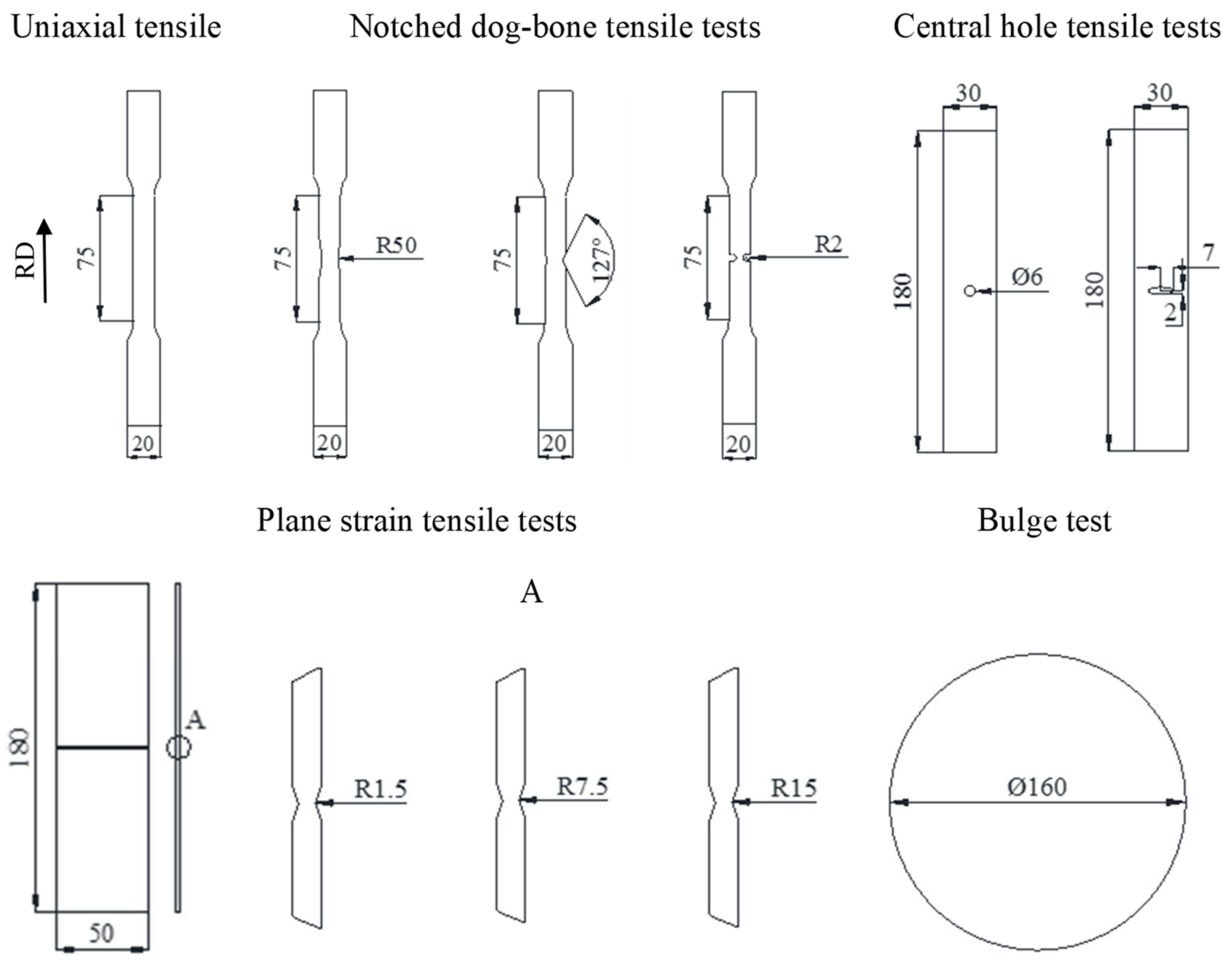
2.2. Experimental Procedure

The effects of different stress states on the damage behavior of the studied DP1000 steels were investigated. In this regard, tensile tests were applied on different geometries, Figure 5, by stroke speed of 0.005 mm/s. Note that a measured gauge length of 50 mm was considered for all the samples. The biaxial deformation mode was applied through a hydraulic bulge test with a stroke speed of 0.02 mm/s, Figure A1. In addition, grooved in-plane torsion tests were carried out in the Institute of Forming Technology and Lightweight Construction at TU Dortmund University. The details of this test were presented by Yin et al. [25]. All the tests were performed along with the 3D digital correlation image (DIC) technique using a camera frequency of 5 s to track the local deformation. The stress triaxiality of the conducted tests was calculated [26,27,28] and summarized in Table A1, which claims that various stress states were studied in the present work. To examine damage evolution in different stress states for each material, fracture sites were examined by scanning electron microscope. For this purpose, the crack initiation sites were observed from normal and side views, as shown in an example of a uniaxial tensile specimen in Figure 5. Moreover, hole expansion tests were performed to investigate the effects of damage mechanisms on the edge crack sensitivity of the materials. In this regard, a 50° conical punch was applied on wire-cut and punched holes with a diameter of 39.67 mm. Note that the punched holes were manufactured with a 10% clearance of the punching die. According to the standard ISO 16630:2017 [29], hole expansion ratios were calculated as a through-thickness edge crack appeared.

3. Results and Discussion

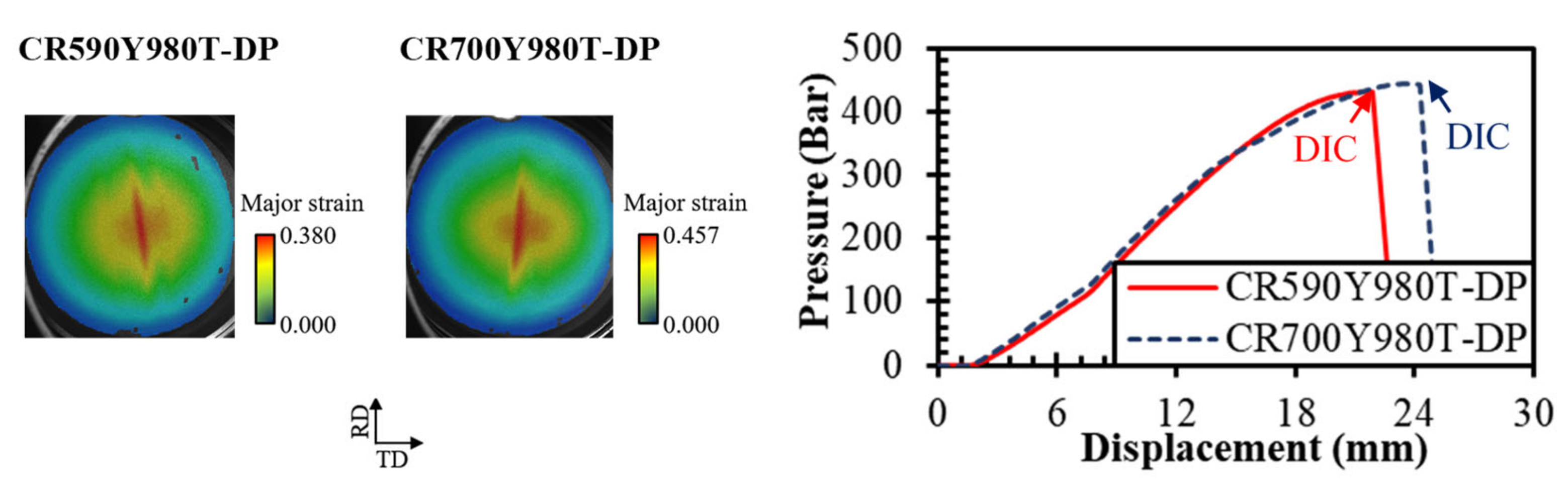
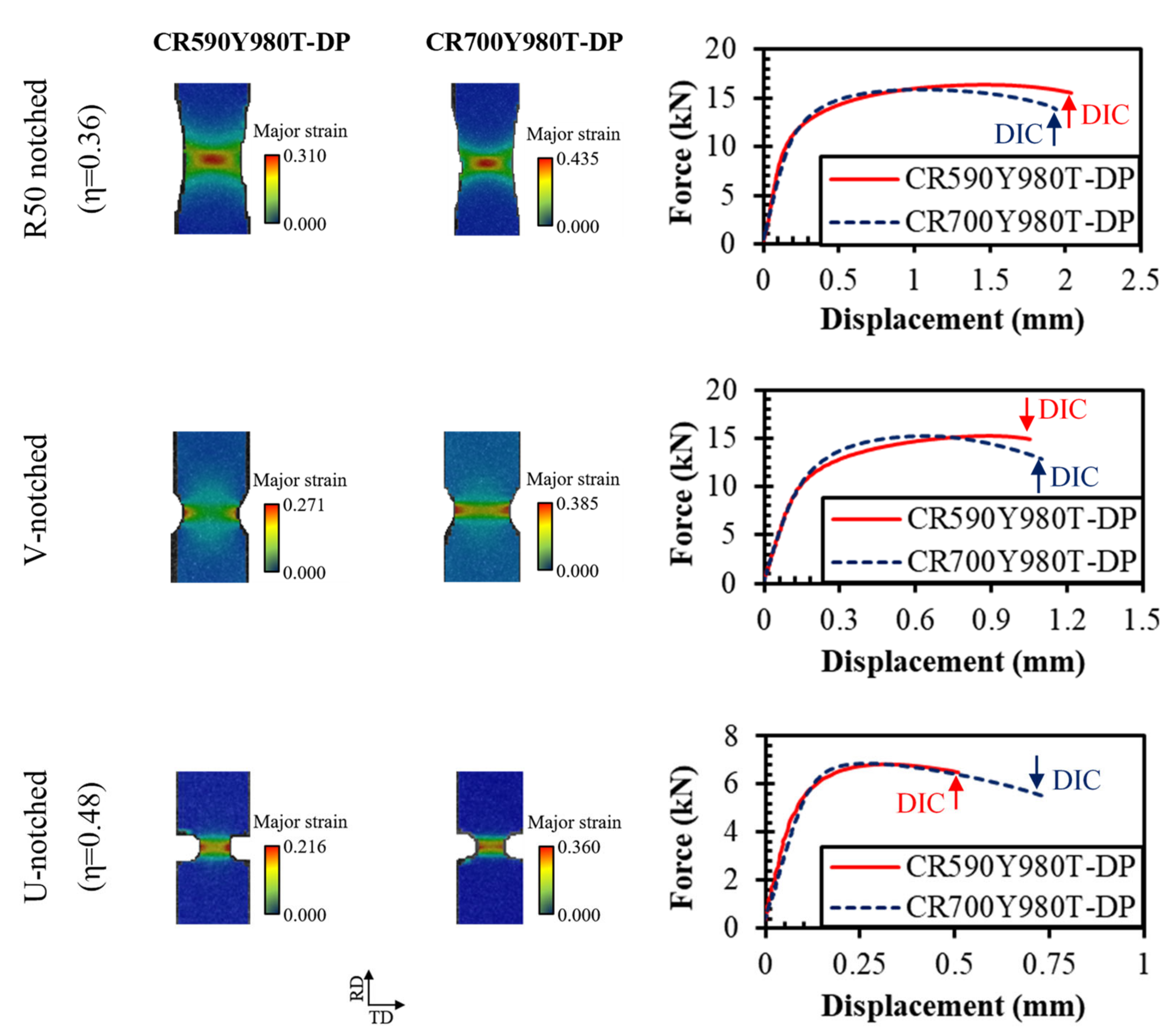
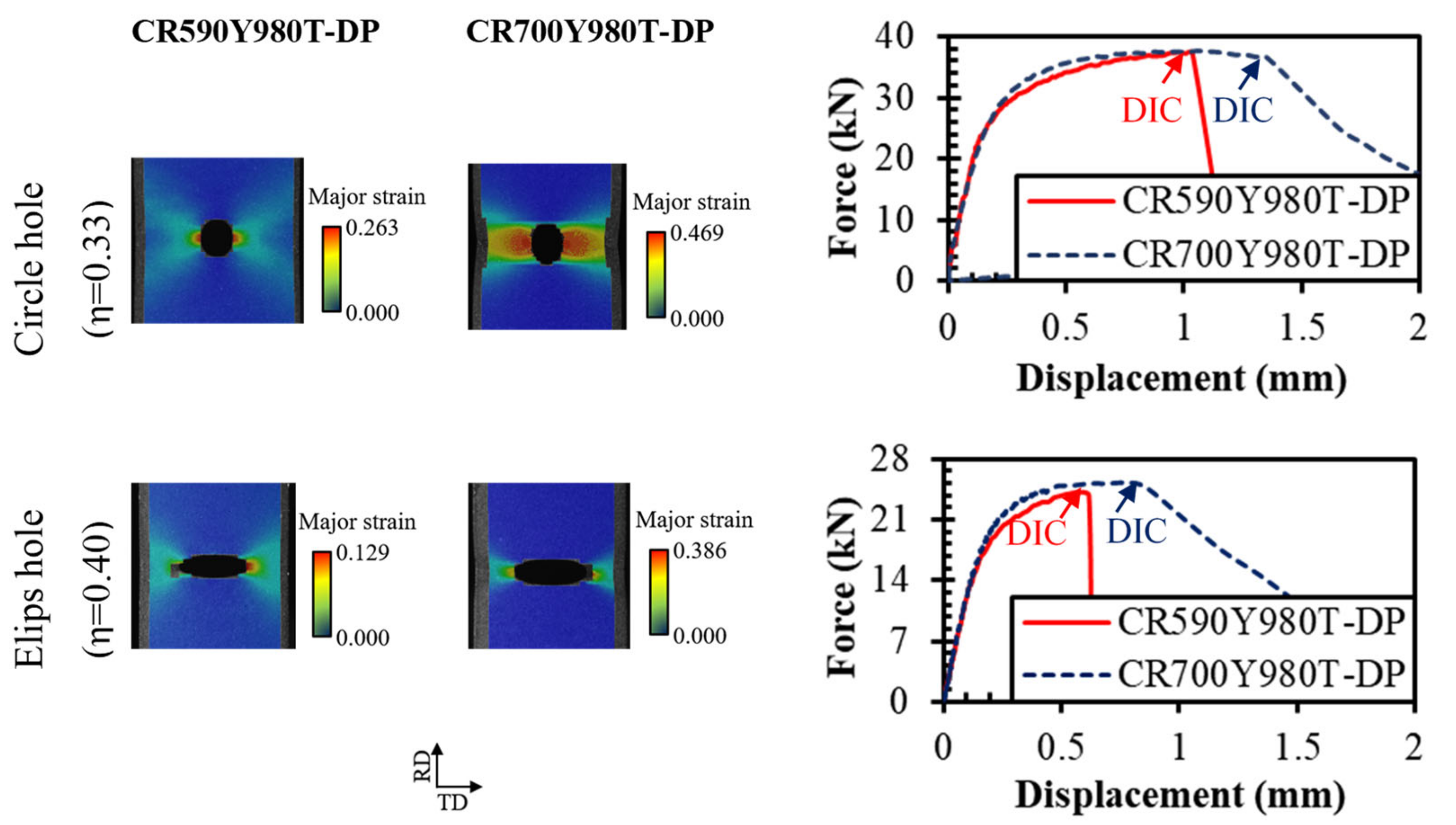
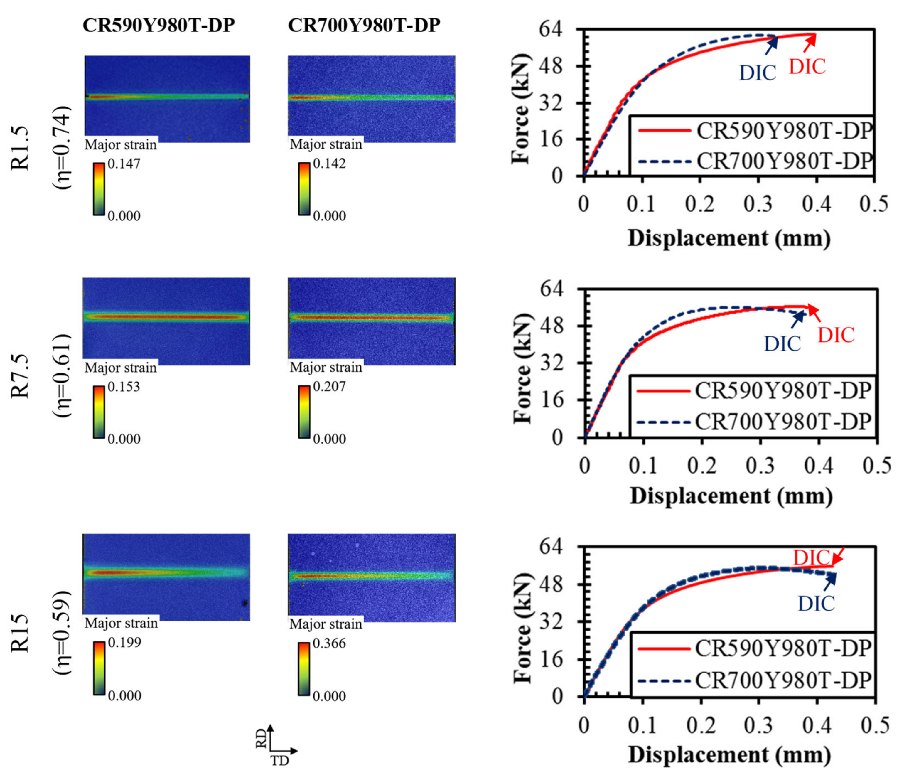
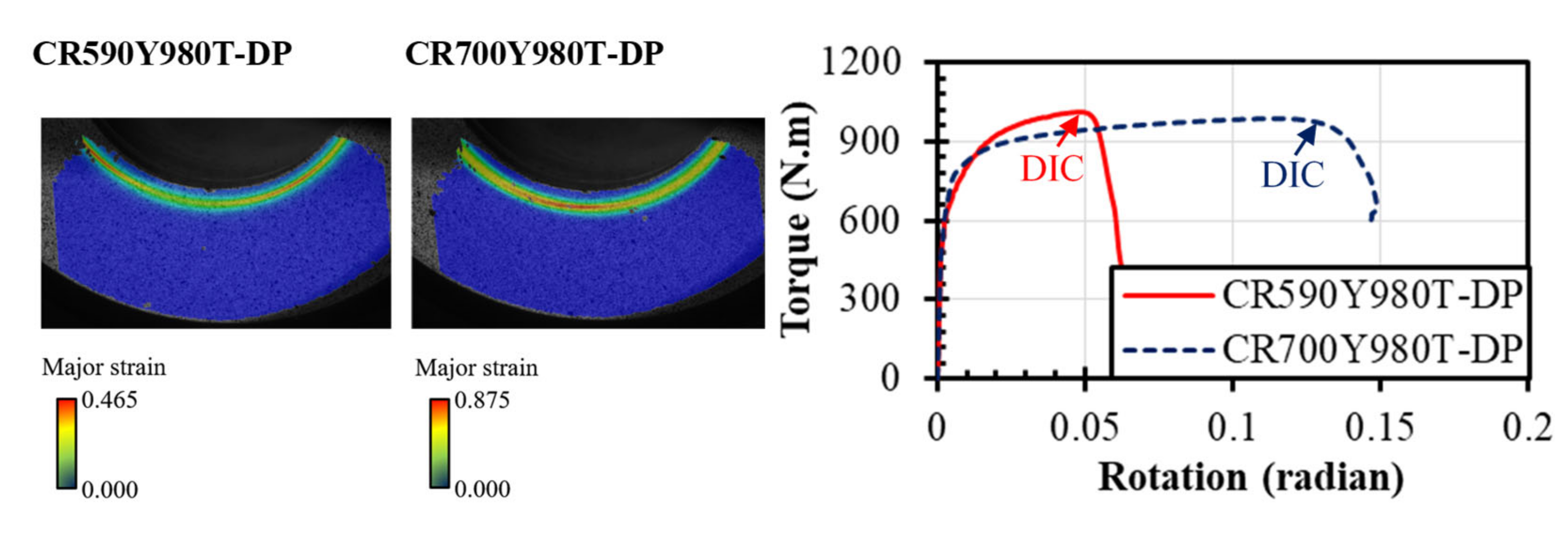
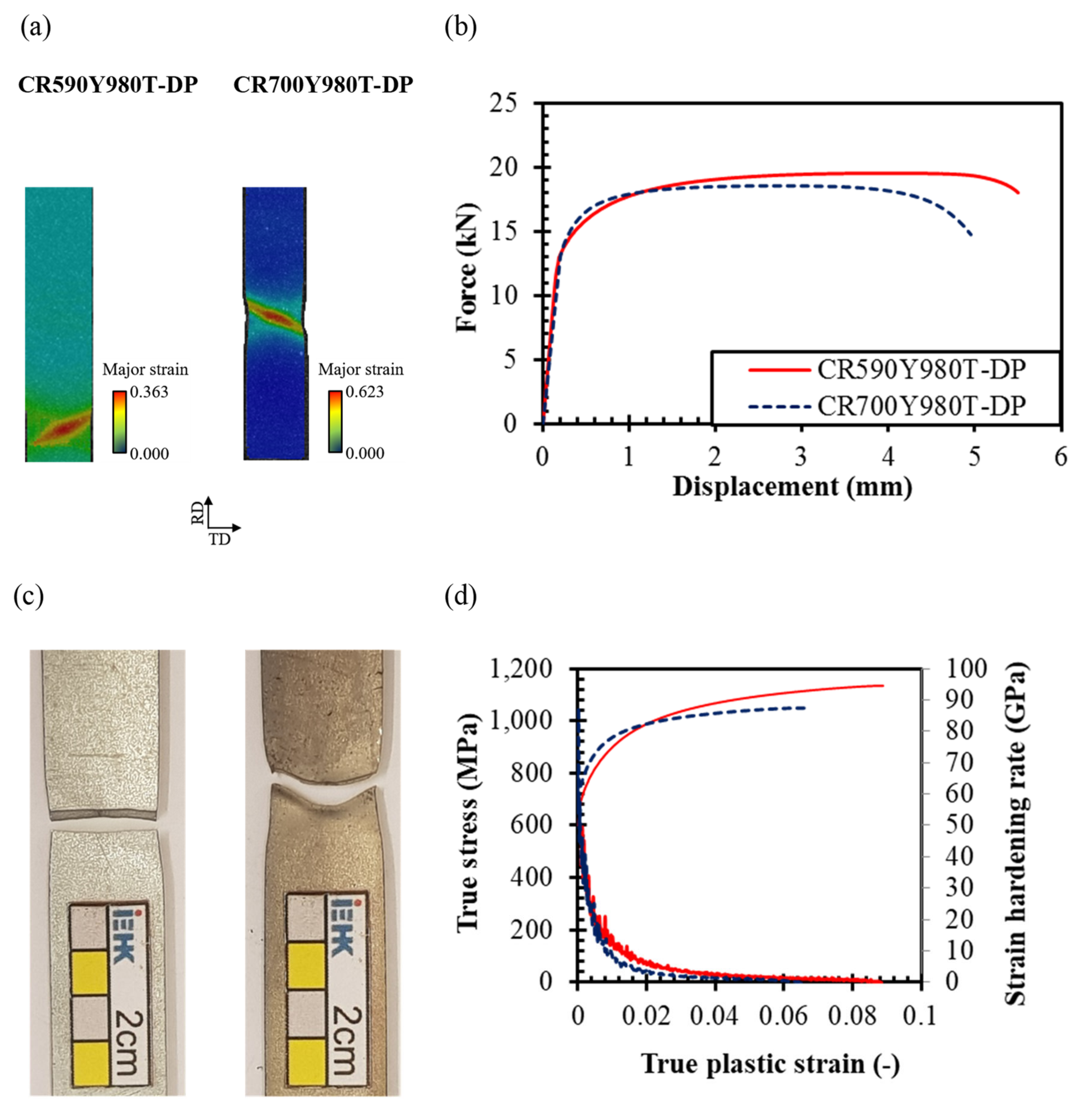
3.1. Mechanical Behavior under Various Stress-States

Mechanical and damage behaviors of the materials through different stress states are presented, compared, and discussed below in terms of forced displacement and local strains. Using the DIC method, the major local strains were taken just before any crack appeared at the surface. With the help of a rainbow-color map of major strain, distribution, and localization of deformation were indicated. Thus, the deformation concentration and crack initiation were displayed by red spots. Figure 6 illustrates responses of the materials through uniaxial tensile tests. As expected, the yield stress and ultimate tensile stress for CR590Y980T-DP were almost 600 and 1020 MPa, and for CR700Y980T-DP were about 700 and 970 MPa. The strain hardening rate and homogenous elongation were higher in CR590Y980T-DP. Although, the post-necking elongation and local strain before fracture were higher in CR700Y980T-DP, which led to pronounced localized necking and fracture with an angle of about 53°, i.e., ductile fracture occurred. Whereas CR590Y980T-DP represented a fracture perpendicular to the loading direction, small localized necking, and lower local strain by DIC, which indicates a less ductile fracture manner. This evidence was also detected by an SEM study on the side and normal views of fracture initiation sites, Figure 7. The thickness of CR590Y980T-DP was reduced from 1.50 mm to 1.28 mm and failed by shearing through the thickness with negligible necking. While in the other material, the thickness was reduced dramatically to 0.68 mm, and the thining was more pronounced. The fracture surfaces in Figure 7b illustrate the relatively smooth surface for CR590Y980T-DP and a rough dimple-like fracture surface for CR700Y980T-DP. However, at the higher magnification in Figure 7c, ductile fracture mechanisms are revealed for both materials with bimodal dimple sizes, fine dimples and big voids which contained non-metallic impurities and inclusions such as TiN and Al2O3. Note that the voids seem finer and deeper in CR700Y980T-DP, and the number of huge voids caused by inclusions was considerable compared to the other steel, Figure 7b.
The same trends were also indicated for the other samples, which represent different stress states. The detailed results are shown in Appendix B, Figure A2, Figure A3, Figure A4, Figure A5, Figure A6, Figure A7, Figure A8 and Figure A9. It can be concluded that steel CR590Y980T-DP showed difficulties in maintaining localized plastic deformation without developing damage and fracture. Thus, its local formability is lower than that of steel CR700Y980T-DP. The reasons for these behaviors are discussed in the following section according to the microstructural features and damage micro-mechanisms of the studied steels.

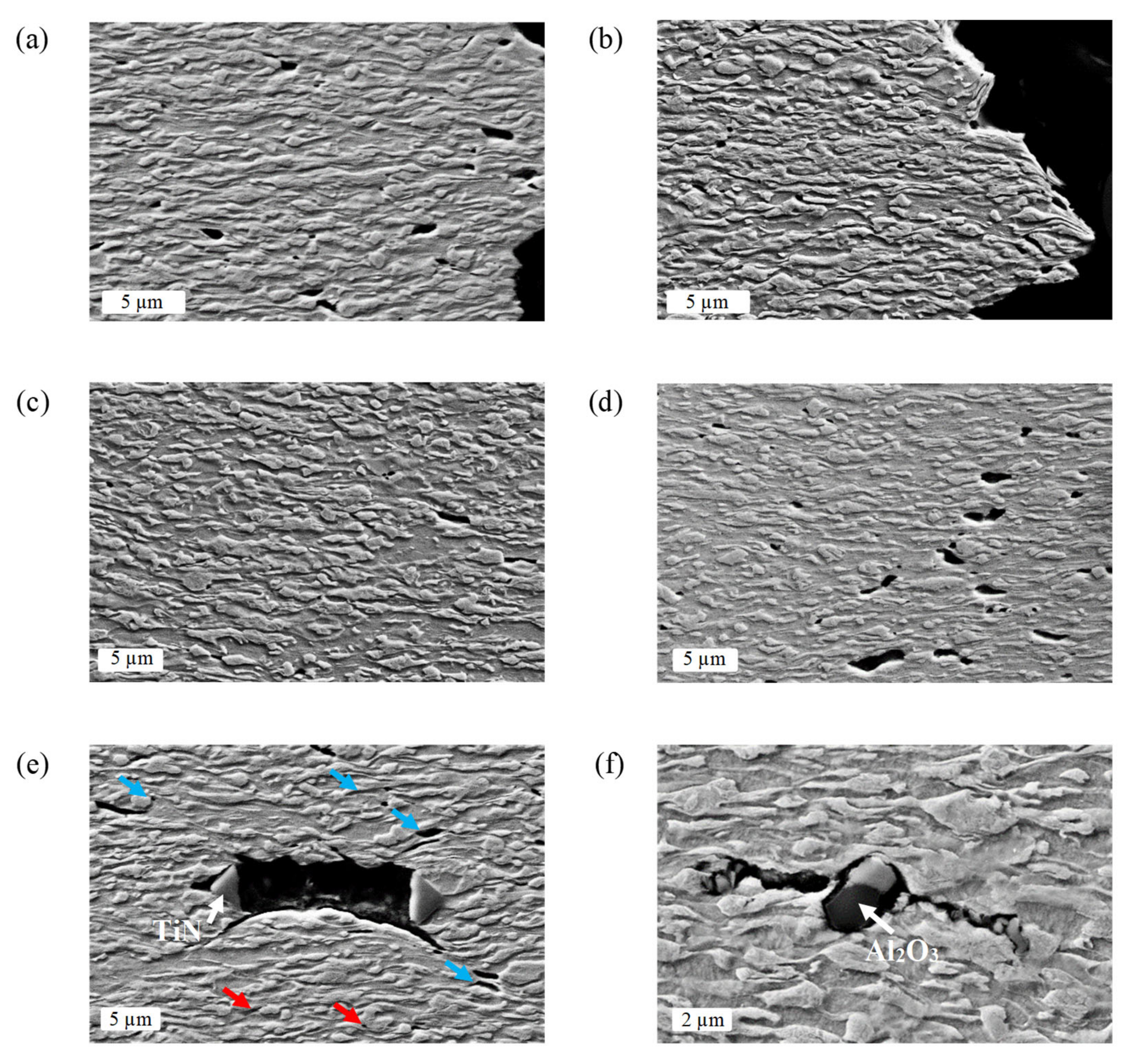
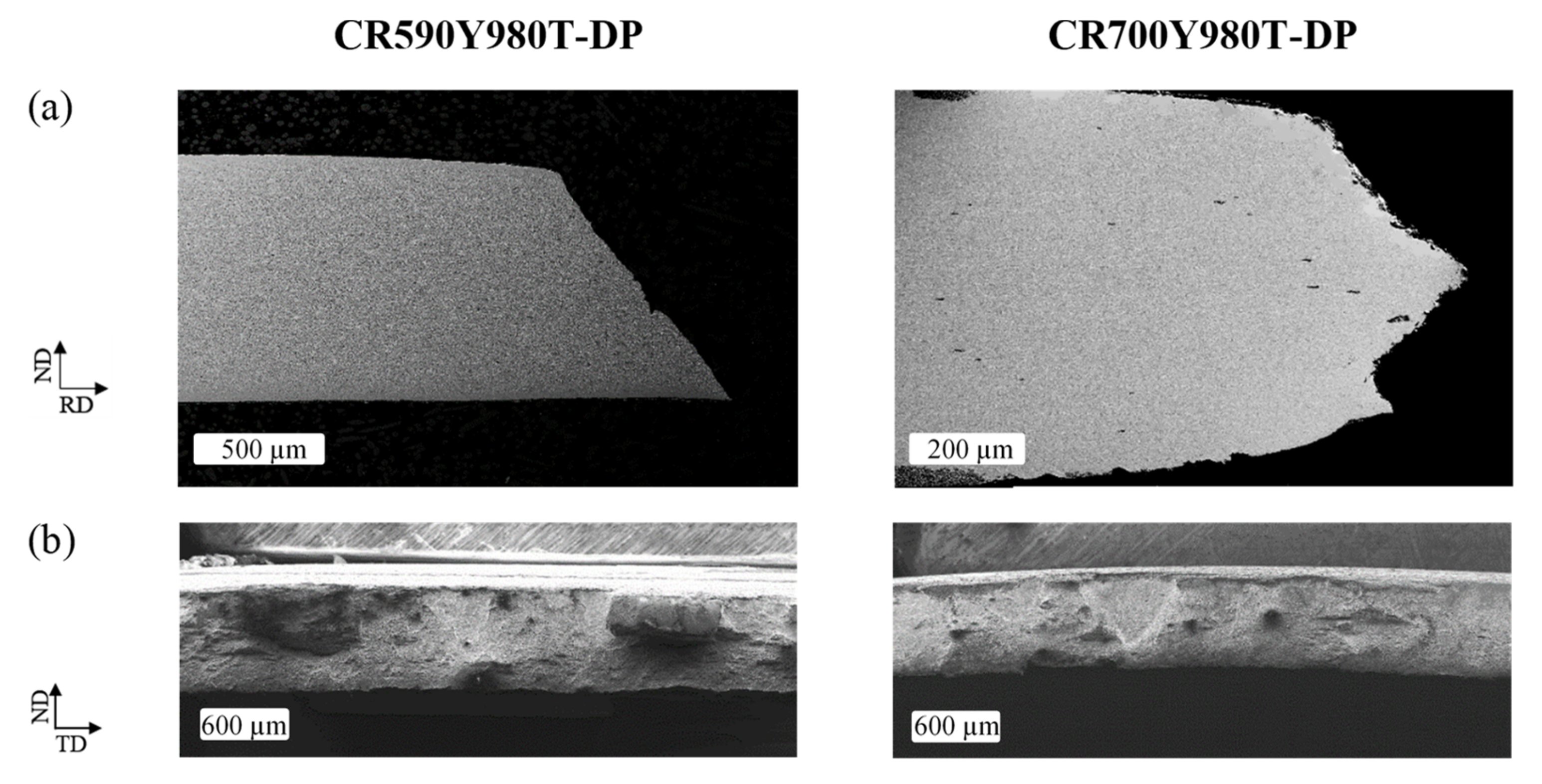
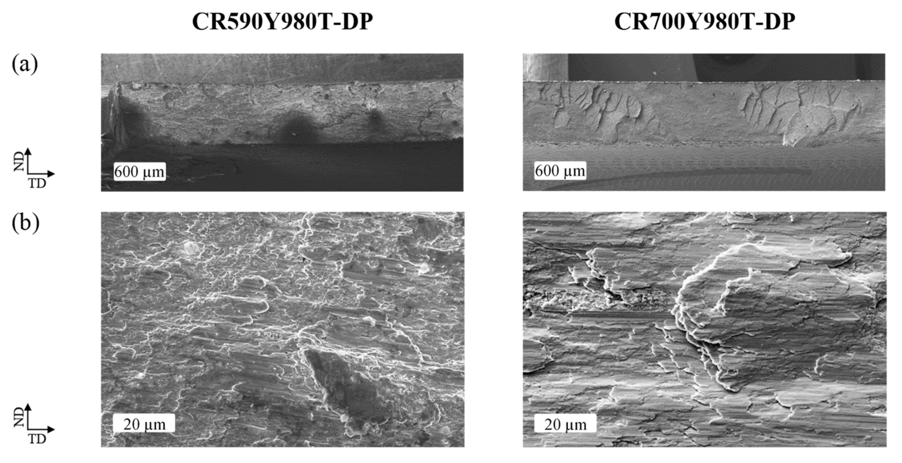
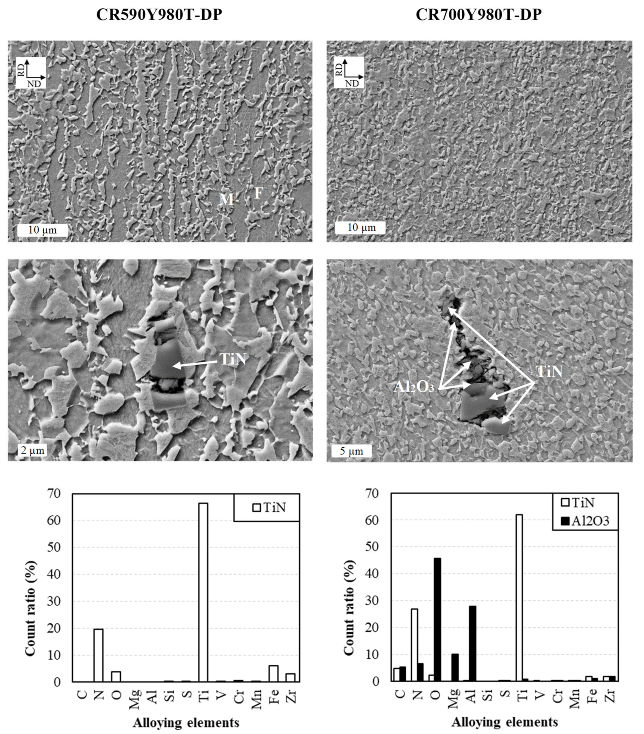
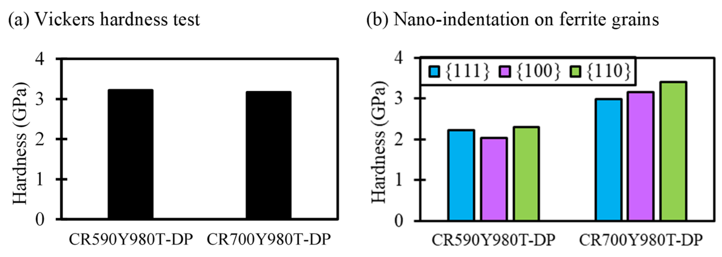
3.2. Damage Micro-Mechanisms

The damage to micro-mechanisms was also investigated by SEM, Figure 8, Figure 9 and Figure 10. The previous studies [18,30] discovered that damage in DP steels nucleates as martensite cracking, decohesion of ferrite-martensite interfaces, failure in a ferrite grain, and cavity formation at TiN particles. Figure 8 illustrates the microstructural changes at the fracture site in CR590Y980T-DP for different stress states. The small voids reveal that the most prominent damage initiation mechanism in this material is martensite cracking. The grown voids imply that the voids caused the separation in martensite islands, passed through the ferrite phase and coalesced through shear bands which formed in the ferrite phase. Several shear bands are marked in Figure 8 by arrows, which induced higher localization and stress triaxiality in the area and led to rapid voids growth and coalescence [31]. This shear linking of voids was also clear in the fracture surface view, Figure 10, where the voids represented the shallow depth and inclined concerning the main loading direction.
In contrast, a different dominant damage micro-mechanism can be detected for CR700Y980T-DP in Figure 9. Evidently, the damage was initiated by decohesion of ferrite-martensite interfaces, which later propagated and elongated along the phase boundaries parallel to the loading direction. Note that no shear bands were formed, which accelerated the damage process. Since the strength differential between ferrite and martensite in this material was very low, based on hardness measurement in Figure 4, the strain partitioning became more even between the phases, and the grain boundaries became the favorable sites of void nucleation. Therefore, the void propagation and coalescence occurred along the grain boundaries towards the loading direction. Furthermore, due to the lower mismatch in strength and morphology (like grain size and shape) throughout this material compared to the other, the amount of void nucleation and propagation was lower, despite the higher strain it experienced at the fracture zone. In addition, it was observed [3] that the damage initiation mechanism for DP steels with large ferrite grains is caused by strain localization inside the phase, like for CR590Y980T-DP. While for DP steels with fine ferrite grains, like for CR700Y980T-DP, it happens due to strain localization at the phase boundaries.
Figure 10 also shows that the voids seem deeper in this material, and they are located towards the normal axis of the fracture surface, which was the loading direction as well. It is worth mentioning that the number of very fine voids is noticeable, which determines that the damage initiated constantly and homogenously at several potential sites, which are the grain boundaries. For this material, numerous huge voids were also observed around the inclusion, even far away from the fracture edges, since it contained a higher amount of Ti and Al. As this material represented ductile behavior in both deformation and failure, it seems inclusions played a minor role in overall damage development.
In brief, the differences in damage mechanisms for these studied steels could be explained by considering the microstructural features and mechanical properties of individual microstructural constituents, which were described previously in Section 2.1. The material experienced higher post-localized deformation when the ferrite and martensite grains were finer, their hardness was closer, and the texture was more similar, i.e., the microstructure and mechanical properties were more homogenous. This phenomenon was also shown in micro-mechanical simulations of DP steels in Ref. [30]. For this material, the dominant damage mechanism was decohesion of ferrite-martensite interfaces, as the strength differential and strain partitioning were low between the phases. The coarser microstructure with high strength mismatch led to damage initiated by martensite cracking at a few sites, recorded in earlier studies. Afterwards, weaker martesites began to deform rapidly along the activated shear bands at the neighbouring ferrite grains, which was also observed by Kang et al. [32].

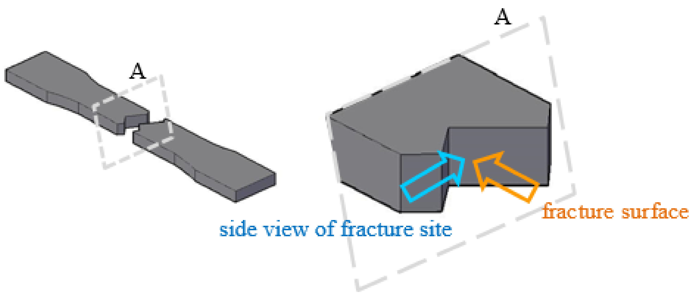
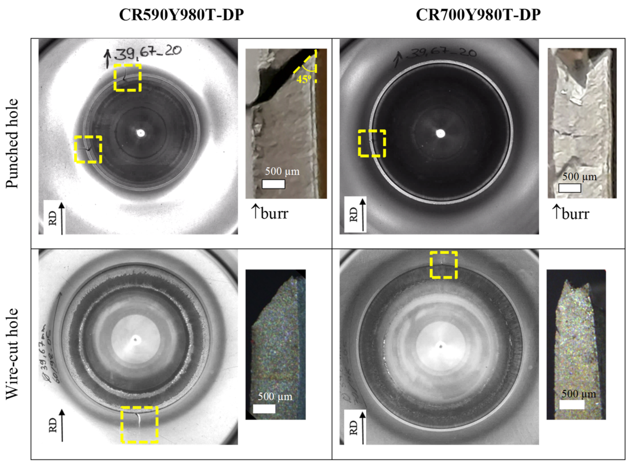
3.3. Edge Crack Sensitivity

The local formability behavior and damage mechanisms play significant roles in the bendability, fracture toughness, and edge-cracking of the materials [33]. Since the studied material in this work represented different damage behaviors, their edge crack sensitivities were also investigated. In this regard, the hole expansion ratio was measured for wire-cut and punched holes, Figure 11 and Figure 12. As expected, HER is higher for wire-cut holes, Figure 12, as this cutting process applies lower damage than punching at the manufactured edges [34]. However, the HER value for wire-cut edges is about quintuple and doubly higher than punched edges for CR590Y980T-DP and CR700Y980T-DP, respectively. This indicates that CR590Y980T-DP is more prone to edge quality and edge cracking. The final edge cracks are illustrated in Figure 11 from the plane and thickness views. The photos were taken at the moment that a through-thickness crack appeared. In all conditions, CR700Y980T-DP sheets experienced more general thinning and deformation through HET than the other material. The cracks prove the contrasting features between the materials, low HER, and shearing through the thickness for CR590Y980T-DP, as well as high HER and significant localization for CR700Y980T-DP. It is worth mentioning that for the wire-cut edge of CR700Y980T-DP, the crack initiates by plane strain necking far from the edge, at the contact site of HE-punch and the specimen. This implies that the residual damage from wire-cutting for this material was very low, which cannot trigger an edge cracking [35]. Furthermore, although several small cracks can be observed at the outer punched edge of CR700Y980T-DP, only one of them was successfully propagated across the thickness and then through the plane of the specimens, which can be explained by taking a look at the residual damage from punching for both materials, Figure 13.
Figure 13 compares the features and residual damage at the edges after the punching process for the investigated materials. Although the sizes of both roll-over and burnished parts are larger for CR700Y980T-DP, no micro-crack can be detected in these parts, even at high magnification. At the same time, several martensite crackings can be easily seen for the other material, Figure 13b. As the stress state at the beginning of punching is pure shearing [36], this behavior was predictable because of the high fracture strain of this material in the pure shearing mode, Figure A8. For both steel subjects, the population of cracks increases in the fractured part of the shear-cut edge, and the highest can be observed at the lower part of the fractured part, close to the burr part. The sizes of burr parts are very small, as reported for other DP steels [34]. Roughly speaking, for CR700Y980T-DP at the punched edge, the observed cracks are fewer, smaller, and mostly took place very close to the cut edge, i.e., lower residual damage from the cutting process. The microstructural and mechanical properties of the phases being so close, Figure 12, made the material more homogenous. Although few large cracks are observed at inclusions and impurities for this material, they are located far from the deformation and fracture sites. Therefore, they could not have any influence on the cut edge property and HER.

4. Conclusions

According to the detailed analyses discussed above, the present study showed the effects of microstructural characteristics on both the macro- and micro-mechanical behaviors of DP steels under various stress state conditions. When the features of the ferrite and martensite phases, in terms of grain sizes, morphology, and mechanical properties, were more similar and homogenous, the damage initiated by decohesion of ferrite-martensite interfaces simultaneously at several sites and induced higher local formability and local fracture strains. In contrast, for coarser and more uneven microstructures with higher strength mismatch, damage occurred due to martensite cracking and rapid propagation through shear bands within adjacent ferrite grains, which significantly restricted the post localized deformation, i.e., the lower local formability. The results revealed that the damage behavior, dictated by the microstructural and micro-mechanical properties of the material, had noticeable effects on the edge cracking sensitivity, which was highly controlled by local ductility. The local formability influenced both residual damage during the edge manufacturing and the edge formability. In the case of similar global ductility in the materials, based on the extracted flow curves from conventional tensile tests, failure through thickness-shearing made rapid crack propagation. At the same time, deformation localization enabled the material to experience more deformation before the fracture. Therefore, HER is higher for the latter. In addition, the material with higher local formability experienced lower damage at the punched edge in terms of the number, size, and location of the micro-cracks. Thus, this material was less sensitive to edge quality, and the reduction of HER was lower.

Author Contributions

Conceptualization, N.H. and S.M. (Sebastian Münstermann); methodology, N.H.; formal analysis, N.H. and S.M. (Santhosh Mathi); investigation, N.H., S.M. (Santhosh Mathi), and T.B.; resources, S.M. (Sebastian Münstermann); writing—original draft preparation, N.H. and S.M. (Santhosh Mathi); writing—review and editing: N.H., M.K. and S.M. (Sebastian Münstermann); supervision, S.M. (Sebastian Münstermann); funding acquisition, S.M. (Sebastian Münstermann). All authors have read and agreed to the published version of the manuscript.

Funding

This research received no external funding.

Data Availability Statement

The data presented in this study are available on request from the corresponding author. The data are not publicly available due to privacy of further investigations.

Acknowledgments

The authors gratefully acknowledge Heinrich Traphoener from IUL, TU Dortmund, for performing in-plane torsion tests.

Conflicts of Interest

The authors declare no conflict of interest. The funders had no role in the design of the study; in the collection, analyses, or interpretation of data; in the writing of the manuscript, or in the decision to publish the results.

Appendix A

A wide range of stress states were applied in this study, using different geometries and testing techniques, Figure A1. The approximate stress triaxiality of each specimen was calculated and listed in Table A1.
Figure A1. The geometries of specimens used for applying different stress states.
Crystals 12 00845 g0a1
Table A1. Average stress triaxiality of the designed specimens.
GeometryStress Triaxiality (η)Reference
Smooth dog bone uniaxial tension0.33[26] *
Notched dog bone uniaxial tension, R500.36[26] *
Notched dog bone uniaxial tension, U-notched0.48[26] *
Central hole uniaxial tension, circle Ø60.33[27] **
Central hole uniaxial tension, oval a2b70.40[27] **
Flat grooved uniaxial tension, R1.50.74[28] *
Flat grooved uniaxial tension, R7.50.61[28] *
Flat grooved uniaxial tension, R150.59[28] *
Bulge test, biaxial tension0.67[28] **
Torsion test0.00[25] **
The values of stress triaxiality are * calculated using the equations proposed in the references. ** directly taken from the references which used the same geometry.

Appendix B

In this appendix, the responses of the studied materials through different stress states are shown, Figure A2, Figure A3, Figure A4, Figure A5, Figure A6, Figure A7, Figure A8 and Figure A9, i.e., the strain distribution captured by DIC and the force-displacement curve. In addition, the fracture mechanisms were compared by observing the evolution of thinning at the fracture site and fracture surfaces of the materials using the SEM method.
Figure A2. Responses of the materials for different notched dogbone specimens.
Crystals 12 00845 g0a2
Figure A3. Responses of the materials for different central hole specimens.
Crystals 12 00845 g0a3
Figure A4. Responses of the materials for different plane strain specimens.
Crystals 12 00845 g0a4
Figure A5. SEM study at fracture sites of R7.5 plane strain tensile tests (η = 0.61) for the materials; (a) thickness views, (b) fracture surfaces.
Crystals 12 00845 g0a5
Figure A6. The strain distribution and materials response for hydraulic bulge test (η = 0.67).
Crystals 12 00845 g0a6
Figure A7. SEM study at fracture sites of hydraulic bulge tests for the materials; (a) thickness views, (b) fracture surfaces.
Crystals 12 00845 g0a7
Figure A8. The strain distribution and materials response for grooved in-plane torsion test (η = 0).
Crystals 12 00845 g0a8
Figure A9. SEM study at fracture sites of in-plane torsion tests (η = 0) for the materials; (a,b) fracture surfaces.
Crystals 12 00845 g0a9

References

  1. Rashid, M. Dual phase steels. Annu. Rev. Mater. Sci. 1981, 11, 245–266. [Google Scholar] [CrossRef]
  2. Tasan, C.C.; Diehl, M.; Yan, D.; Bechtold, M.; Roters, F.; Schemmann, L.; Zheng, C.; Peranio, N.; Ponge, D.; Koyama, M. An overview of dual-phase steels: Advances in microstructure-oriented processing and micromechanically guided design. Annu. Rev. Mater. Res. 2015, 45, 391–431. [Google Scholar] [CrossRef]
  3. Darabi, A.C.; Chamani, H.; Kadkhodapour, J.; Anaraki, A.; Alaie, A.; Ayatollahi, M. Micromechanical analysis of two heat-treated dual phase steels: DP800 and DP980. Mech. Mater. 2017, 110, 68–83. [Google Scholar] [CrossRef]
  4. Qin, S.; McLendon, R.; Oancea, V.; Beese, A.M. Micromechanics of multiaxial plasticity of DP600: Experiments and microstructural deformation modeling. Mater. Sci. Eng. A 2018, 721, 168–178. [Google Scholar] [CrossRef]
  5. Zarei, S.; Nedoushan, R.J.; Atapour, M. The sources of the micro stress and strain inhomogeneity in dual phase steels. Mater. Sci. Eng. A 2016, 674, 384–396. [Google Scholar] [CrossRef]
  6. Han, S.; Chang, Y.; Wang, C.Y.; Dong, H. A comprehensive investigation on the damage induced by the shearing process in DP780 steel. J. Mater. Processing Technol. 2022, 299, 117377. [Google Scholar] [CrossRef]
  7. Hu, X.; Sun, X.; Raghavan, K.; Comstock, R.; Ren, Y. Linking constituent phase properties to ductility and edge stretchability of two DP 980 steels. Mater. Sci. Eng. A 2020, 780, 139176. [Google Scholar] [CrossRef]
  8. Pan, L.; Xiong, J.; Zuo, Z.; Tan, W.; Wang, J.; Yu, W. Study of the stretch-flangeability improvement of dual phase steel. Procedia Manuf. 2020, 50, 761–764. [Google Scholar] [CrossRef]
  9. Balisetty, V.; Chakkingal, U.; Venugopal, S. Evaluation of stretch flangeability of dual-phase steels by hole expansion test. Int. J. Adv. Manuf. Technol. 2021, 114, 205–217. [Google Scholar] [CrossRef]
  10. Moura, A.N.; Ferreira, J.L.; Martins, J.B.R.; Souza, M.V.; Castro, N.A.; Orlando, M.T.D.A. Microstructure, crystallographic texture, and stretch-flangeability of hot-rolled multiphase steel. Steel Res. Int. 2020, 91, 1900591. [Google Scholar] [CrossRef]
  11. Terrazas, O.R.; Findley, K.O.; Van Tyne, C.J. Influence of martensite morphology on sheared-edge formability of dual-phase steels. ISIJ Int. 2017, 57, 937–944. [Google Scholar] [CrossRef] [Green Version]
  12. Kadkhodapour, J.; Butz, A.; Rad, S.Z. Mechanisms of void formation during tensile testing in a commercial, dual-phase steel. Acta Mater. 2011, 59, 2575–2588. [Google Scholar] [CrossRef]
  13. Li, S.; Guo, C.; Hao, L.; Kang, Y.; An, Y. In-situ EBSD study of deformation behaviour of 600 MPa grade dual phase steel during uniaxial tensile tests. Mater. Sci. Eng. A 2019, 759, 624–632. [Google Scholar] [CrossRef]
  14. Lian, J.; Yang, H.; Vajragupta, N.; Münstermann, S.; Bleck, W. A method to quantitatively upscale the damage initiation of dual-phase steels under various stress states from microscale to macroscale. Comput. Mater. Sci. 2014, 94, 245–257. [Google Scholar] [CrossRef]
  15. Münstermann, S.; Lian, J.; Pütz, F.; Könemann, M.; Brinnel, V. Comparative study on damage evolution during sheet metal forming of steels dp600 and dp1000. J. Phys. Conf. Ser. 2017, 896, 012074. [Google Scholar] [CrossRef] [Green Version]
  16. Ghassemi-Armaki, H.; Maaß, R.; Bhat, S.; Sriram, S.; Greer, J.; Kumar, K. Deformation response of ferrite and martensite in a dual-phase steel. Acta Mater. 2014, 62, 197–211. [Google Scholar] [CrossRef]
  17. Steinbrunner, D.L.; Matlock, D.; Krauss, G. Void formation during tensile testing of dual phase steels. Metall. Trans. A 1988, 19, 579–589. [Google Scholar] [CrossRef]
  18. Ghadbeigi, H.; Pinna, C.; Celotto, S. Failure mechanisms in DP600 steel: Initiation, evolution and fracture. Mater. Sci. Eng. A 2013, 588, 420–431. [Google Scholar] [CrossRef]
  19. Darabi, A.C.; Guski, V.; Butz, A.; Kadkhodapour, J.; Schmauder, S. A comparative study on mechanical behavior and damage scenario of DP600 and DP980 steels. Mech. Mater. 2020, 143, 103339. [Google Scholar] [CrossRef]
  20. Darabi, A.C.; Kadkhodapour, J.; Anaraki, A.P.; Khoshbin, M.; Alaie, A.; Schmauder, S. Micromechanical modeling of damage mechanisms in dual-phase steel under different stress states. Eng. Fract. Mech. 2021, 243, 107520. [Google Scholar] [CrossRef]
  21. Sun, X.; Choi, K.S.; Liu, W.N.; Khaleel, M.A. Predicting failure modes and ductility of dual phase steels using plastic strain localization. Int. J. Plast. 2009, 25, 1888–1909. [Google Scholar] [CrossRef]
  22. Lai, Q.; Bouaziz, O.; Gouné, M.; Brassart, L.; Verdier, M.; Parry, G.; Perlade, A.; Bréchet, Y.; Pardoen, T. Damage and fracture of dual-phase steels: Influence of martensite volume fraction. Mater. Sci. Eng. A 2015, 646, 322–331. [Google Scholar] [CrossRef]
  23. Kusche, C.; Reclik, T.; Freund, M.; Al-Samman, T.; Kerzel, U.; Korte-Kerzel, S. Large-area, high-resolution characterisation and classification of damage mechanisms in dual-phase steel using deep learning. PLoS ONE 2019, 14, e0216493. [Google Scholar] [CrossRef] [Green Version]
  24. Kusche, C.F.; Pütz, F.; Münstermann, S.; Al-Samman, T.; Korte-Kerzel, S. On the effect of strain and triaxiality on void evolution in a heterogeneous microstructure–A statistical and single void study of damage in DP800 steel. Mater. Sci. Eng. A 2021, 799, 140332. [Google Scholar] [CrossRef]
  25. Yin, Q.; Tekkaya, A.E.; Traphöner, H. Determining cyclic flow curves using the in-plane torsion test. CIRP Ann. 2015, 64, 261–264. [Google Scholar] [CrossRef]
  26. Selini, N.; Elmeguenni, M.; Benguediab, M. Effect of the triaxiality in plane stress conditions. Triaxiality effect in a PVC material. Eng. Technol. Appl. Sci. Res. 2013, 3, 373–380. [Google Scholar] [CrossRef]
  27. Lian, J.; Sharaf, M.; Archie, F.; Münstermann, S. A hybrid approach for modelling of plasticity and failure behaviour of advanced high-strength steel sheets. Int. J. Damage Mech. 2013, 22, 188–218. [Google Scholar] [CrossRef]
  28. Bai, Y.; Teng, X.; Wierzbicki, T. Study on the effect of the third stress invariant on ductile fracture. Rep. Camb. 2006. [Google Scholar]
  29. ISO16630:2017; Metallic Materials—Sheet and Strip—Hole Expanding Test. ISO: Geneva, Switzerland, 2017.
  30. Habibi, N.; Vajragupta, N.; Münstermann, S. Deformation and damage assessments of Two DP1000 steels using a micromechanical modelling method. Crystals 2021, 11, 805. [Google Scholar] [CrossRef]
  31. He, X.; Terao, N.; Berghezan, A. Influence of martensite morphology and its dispersion on mechanical properties and fracture mechanisms of Fe-Mn-C dual phase steels. Met. Sci. 1984, 18, 367–373. [Google Scholar] [CrossRef]
  32. Kang, J.; Ososkov, Y.; Embury, J.D.; Wilkinson, D.S. Digital image correlation studies for microscopic strain distribution and damage in dual phase steels. Scr. Mater. 2007, 56, 999–1002. [Google Scholar] [CrossRef]
  33. Heibel, S.; Dettinger, T.; Nester, W.; Clausmeyer, T.; Tekkaya, A.E. Damage mechanisms and mechanical properties of high-strength multiphase steels. Materials 2018, 11, 761. [Google Scholar] [CrossRef] [PubMed] [Green Version]
  34. Pathak, N.; Butcher, C.; Worswick, M.J.; Bellhouse, E.; Gao, J. Damage evolution in complex-phase and dual-phase steels during edge stretching. Materials 2017, 10, 346. [Google Scholar] [CrossRef] [PubMed] [Green Version]
  35. Krempaszky, C.; Larour, P.; Freudenthaler, J.; Werner, E. Towards more efficient hole expansion testing. In Proceedings of the IDDRG 2014 Conference, Paris, France, 1–4 June 2014; pp. 204–209. [Google Scholar]
  36. Habibi, N.; Beier, T.; Richter, H.; Könemann, M.; Münstermann, S. The effects of shear affected zone on edge crack sensitivity in dual-phase steels. In IOP Conference Series: Materials Science and Engineering; IOP Publishing: Bristol, UK, 2019; p. 012073. [Google Scholar]
Figure 1. SEM study on the initial microstructures in the ND-RD plane, which shows the distribution of ferrite (F) and Martensite (M) in the materials. TiN and Al2O3 particles were also detected.
Crystals 12 00845 g001
Figure 2. The texture analysis using EBSD for as-received materials; (a) crystallographic misorientation of grains, (b) inverse pole figures.
Crystals 12 00845 g002
Figure 3. Comparison of grain size distribution of ferrite and martensite phases for each studied steel alloy.
Crystals 12 00845 g003
Figure 4. Comparison of Hardness between the studied steels; (a) standard Vickers hardness, and (b) Nano-indentation on ferrite grains with crystallographic orientations close to {111} (in blue), {100} (in purple), and {110} (in green).
Crystals 12 00845 g004
Figure 5. Damage evolution was studied at the crack initiation site from different views by SEM.
Crystals 12 00845 g005
Figure 6. Responses of the materials through uniaxial tensile tests (η = 0.33); (a) strain distribution by DIC at the fracture moment, (b) force-displacement curves, (c) fracture positions, and (d) Stress-strain and strain hardening rate curves of the studied materials through homogenous plastic elongation.
Crystals 12 00845 g006
Figure 7. SEM study at fracture sites of uniaxial tensile tests (η = 0.33) for the materials; (a) thickness views, (b,c) fracture surfaces.
Crystals 12 00845 g007
Figure 8. Damage mechanisms in CR590Y980T-DP steel in different stress states; (a,b) uniaxial tensile test, (c) U-notched tensile test, (d) plane strain tensile test, (e,f) bulge test. The arrows show some micro damage mechanisms: Yellow = shear bands and shear linking of the voids, Red = martensite cracking, and Blue = decohesion between ferrite and martensite phases. As the number of voids in the figures is significant, only a few were marked to avoid covering the picture details.
Crystals 12 00845 g008
Figure 9. Damage mechanisms in CR700Y980T-DP steel in different stress states; (a) uniaxial tensile test, (b) U-notched tensile test, (c) plane strain tensile test, (d) bulge test. Cracking around the non-metallic inclusions (e) TiN and (f) Al2O3. The arrows show some micro damage mechanisms: Red = martensite cracking, Blue = decohesion between ferrite and martensite phases.
Crystals 12 00845 g009
Figure 10. Comparison of fracture surfaces for 7.5 plane strain tensile specimens reveals different damage micro-mechanisms in these materials.
Crystals 12 00845 g010
Figure 11. Comparison of edge-crack initiation in these steel for punched and wire-cut holes.
Crystals 12 00845 g011
Figure 12. Comparison of the hole expansion ratio and microstructural characteristics of studied materials.
Crystals 12 00845 g012
Figure 13. Induced damage through the punching process, (a) the punched edge, (b) the roll-over and burnished part, (c) the fractured part, and (d) the burr part.
Crystals 12 00845 g013
Table 1. Chemical compositions of the investigated steels (wt.%).
Steel GradeCSiMnPSAlTi
CR590Y980T-DP0.0430.3011.8070.0120.0070.0370.048
CR700Y980T-DP0.0800.2932.8130.0110.0020.2910.075
Publisher’s Note: MDPI stays neutral with regard to jurisdictional claims in published maps and institutional affiliations.

