Article

Dynamic Response and Numerical Interpretation of Three Kinds of Metals for EFP Liner under Explosive Loading

1
School of Mechanical Engineering, Nanjing University of Science & Technology, Nanjing 210094, China
2
Xi’an Modern Control Technology Institute, Xi’an 710065, China
*
Author to whom correspondence should be addressed.
Crystals 2022, 12(2), 154; https://doi.org/10.3390/cryst12020154
Submission received: 17 December 2021 / Revised: 12 January 2022 / Accepted: 14 January 2022 / Published: 21 January 2022
(This article belongs to the Special Issue Dynamic Behavior of Materials)

Abstract

:
In order to study the dynamic response of tungsten heavy alloy materials under explosive loading, two kinds of typical tungsten alloys for explosively formed projectile (EFP) liner and one kind of existing EFP liner were tested in a flash X-ray experiment, with copper liner as a reference. Results showed that copper liner could form a coherent EFP, while 90W–9Ni–Co and W–25Re liners fractured to different extents. The microscopic features of the three kinds of metals were examined and compared with the original liner, and the microstructure evolutions under explosive loading were analyzed with the fracture model and mechanism of the two kinds of tungsten alloys’ fracture determined. Associated with the stress and strain conditions by numerical simulation, the fracture mechanism of tungsten heavy alloys can be analyzed. The crack-tip plastic zones of 90W–9Ni–Co and W–25Re are much smaller than copper, and due to the severe stress concentration at the tip of cracks, it is easy for cracks to propagate and trigger the cleavage in tungsten alloys. The value of a crack-tip plastic zone r(θ) can be used to explain the fracture phenomenon in explosive loading, which can be an alternative guideline for the material selection criteria of the EFP liner. The research results are significant in understanding the dynamic forming, microstructure evolution, and fracture mechanism of tungsten heavy alloys.

1. Introduction

According to the shaped-charge mechanism, the explosively formed projectile (EFP) makes full use of explosive blasting to form the liner into a preferred penetrator without breaking [1,2,3]. The liner of EFP should undergo extremely, yet controlled, plastic deform, which makes designing an optimal EFP a very complicated task [4]. The preferable properties of EFP liner material are high density, high ductility, high strength, and a high enough melting point to avoid melting in the liner due to adiabatic heating under explosive loading. The most common liner materials for EFP are copper (Cu), ferrum (Fe), tantalum (Ta), and Ta-W alloys.
Manfred Held [5] showed a comparison of liner materials with their densities, bulk-sound velocities, possible maximum jet tip velocities, and a ranking based on the product of possible jet tip velocities and square root of density. The ranking results clearly shows that tungsten has particularly good potential for a shaped-charge liner. However, whether tungsten can be used as an EFP liner has not been discussed.
The good mechanical properties of tungsten and its alloys have drawn much attention in recent years, especially in military applications. The high density (19.3 g/cm3), high strength, high sound speed, high melting point (3410 °C), and excellent corrosion resistance make tungsten alloys desirable materials for use as a shaped-charge liner or ballistic penetrator [6,7]. Tungsten in its pure state has limitations, especially the low-temperature brittleness, which restricts its application. Alloys of tungsten with nickel, cobalt, ferrum, or rhenium have witnessed tremendous improvement in mechanical properties at lowering the ductile-to-brittle transition temperature (DBTT). Therefore, it is essential to combine tungsten with other alloying elements to form an alloy for its applications in Tungsten heavy alloys (WHA), defense, and other military applications [8,9,10,11].
Michael T. Stawovy [12,13] submitted patents explaining a single-phase tungsten alloy that could be used for forming a shaped-charge liner for a penetrating jet or explosively formed penetrator. The alloy is essentially composed of cobalt, tungsten, and nickel. One preferred composition is, by weight, from 16% to 20% cobalt, from 35% to 40% tungsten, and the balance is nickel and inevitable impurities. The tungsten alloy is worked and recrystallized and then formed into the desired product. However, relevant experimental results were not provided to verify his viewpoint.
S. Rolc et al. [14] conducted a numerical simulation of linear EFP with different materials (copper, iron, tungsten, MONEL Alloy 400, INONEL Alloy 600, INCONEL Alloy 625, INCO Alloy HX, INCOLOY Alloy 800 HT, nickel 200, and Hadfield steel) and found they could all form complete EFPs in the simulation. C. G. Bingol et al. [15] carried out a numerical investigation of the thickness and radius of curvature of the liner on the formation of EFP and found that tungsten, nickel 200, and molybdenum could form EFP as well as copper and tantalum. However, only an experiment of Cu EFP was presented to testify his conclusion. Among their research, whether liners of tungsten and its alloys could form EFPs and the dynamic response of tungsten liner under explosive loading have not yet been studied in experiments. Weibing Li et al. [16] investigated the effect of liner material density and elongation on the shape of dual mode penetrators. However, as a promising liner material, tungsten alloy was studied only in numerical simulation. Yajun Wang et al. [17] carried out a numerical simulation on the relationship between structural characteristics and materials of liner on EFP formation. The liner of tungsten alloy could form complete EFPs with low solidity in the numerical simulation. However, their numerical simulation results have not yet been validated in experiments.
Robert P. Koch et al. [18] carried out experiments to study the performance of a two phase tungsten tungsten–nickel–iron heavy alloy (W–Ni–Fe) and a single phase nickel–tungsten alloy (Ni–W) when used as MEFP liner. They found that W–Ni–Fe heavy alloy liner with a density of 17.1 g/cm3 fractured into pieces in the charge structure designed for minimal deformation, while both the W–Ni–Fe heavy alloy liner and the Ni–W alloy liner with a density of 11.1 g/cm3 fractured into pieces, but the potential reasons for the fracture phenomenon have not been analyzed. The radiograph of the X-ray experiment and soft recovered tungsten alloy penetrators from the tests clearly showed the fracture characteristics with charge structure for severe deformation.
In this paper, three kinds of metal materials for EFP liner are selected to be tested under explosive loading, within which 90W–9Ni–Co and W–25Re are tested as two kinds of typical tungsten heavy alloy and copper as a validated EFP liner material reference. The dynamic response and the formation characteristic were observed by a flash X-ray experiment.
In order to explain the different responses of the three kinds of metals, the microscopic features were examined and compared in the original liner and recovered fragment. The fracture models were determined and the microstructure evolutions under explosive loading were analyzed. Associated with numerical simulation results and fracture mechanics, the fracture mechanism of the two kinds of tungsten alloys were analyzed.

2. Experimental Details and Results

2.1. Experimental Details

Parameters of the three kinds of metal material for the EFP liner are listed in Table 1. As two kinds of typical tungsten alloy with good plasticity, 90W–9Ni–Co and W–25Re alloy have much higher density and yield stress compared with copper (OFHC, oxygen-free high-conductivity copper). However, copper has better ductility than the two kinds of heavy tungsten alloys. Powder metallurgy is used to produce the 90W–9Ni–Co and W–25Re alloy liner. According to the structure of liner, preparation procedures of tungsten alloy liner are set below: a. mixing of powder; b. isostatic pressing of performs; c. sintering; d. rolling to sheet; e. annealing; and f. stamping or machining to liners.
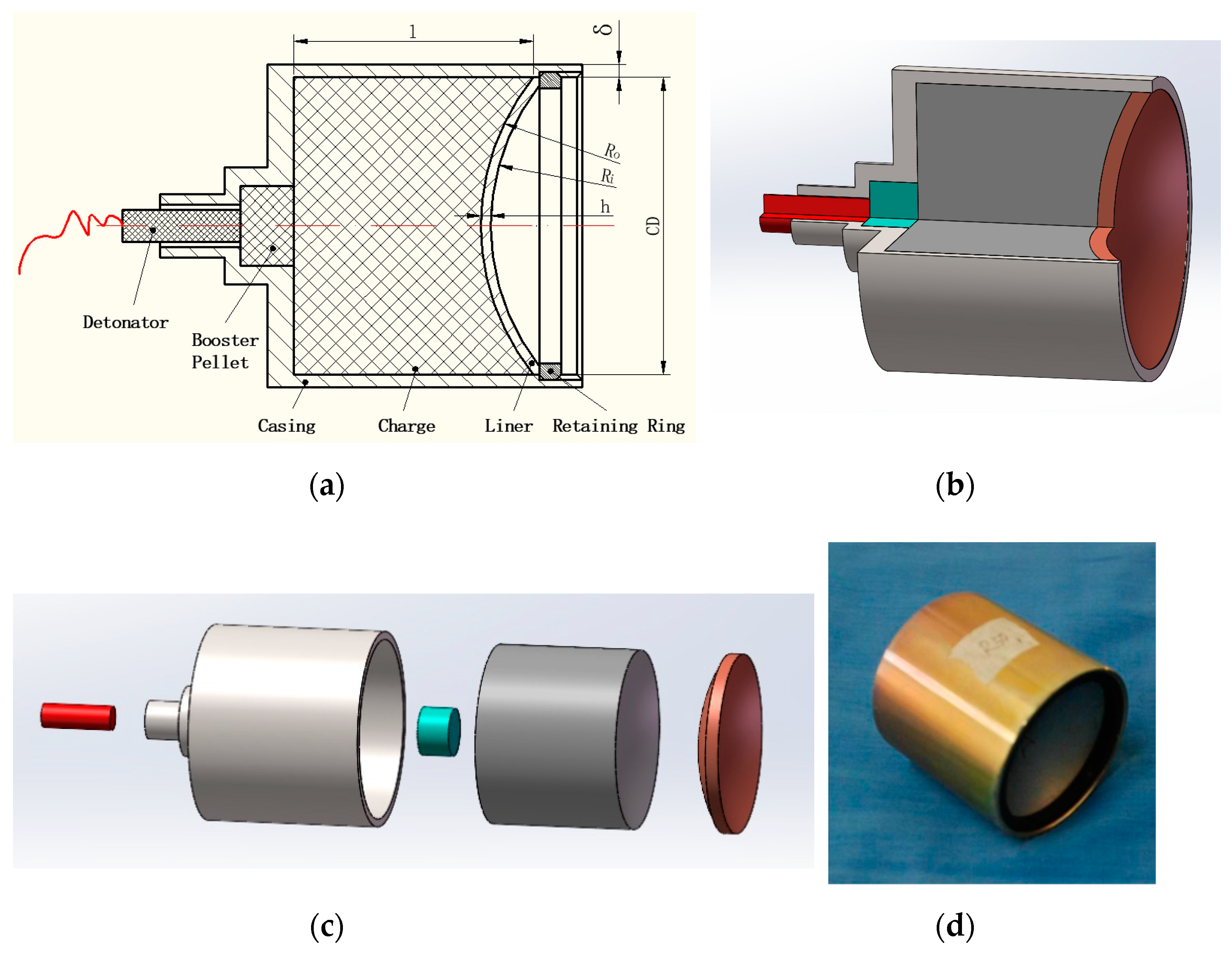
Figure 1 shows the EFP charge structure. As shown in Figure 1a, the EFP charge structure is composed of a detonator, booster pellet, casing, charge, liner, and retaining ring. The charge is made of explosive 8701, which is a kind of RDX-based explosive, with a density of 1.71 g/cm3. The detonation velocity of the explosive is 8315 m/s. The length to diameter ration of the charge is 0.8. The length and diameter of the charge are denoted as l and CD. For the hemispherical liners, Ri is the liner’s inner curvature, while Ro is the outer curvature (next to the charge), and h is the thickness of the liner. For the constant thickness of the liner used in this paper, h equals RoRi. The mass of the liner for the three kinds of metal material stays the same. The material of casing is steel #45, with a thickness denoted as δ which equals to 0.045 CD. The retaining ring is also made of steel #45. Figure 1b shows the 3D geometric sketch of the EFP charge structure. The components structure is shown in Figure 1c and the assembly status of the EFP structure in the experiment is presented in Figure 1d.
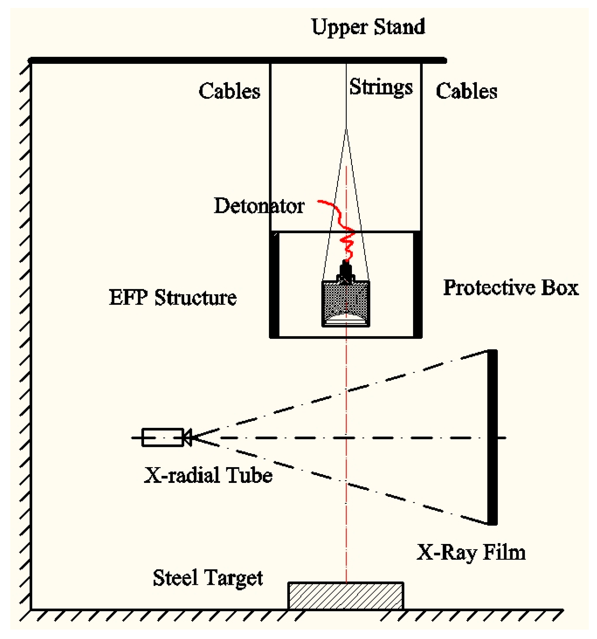
Then flash X-ray experiment was carried out to observe the dynamic response and formation characteristic of liners. The schematic diagram of the flash X-ray experiment of the EFP is shown in Figure 2. Scandiflash-450 system is used for the flash X-ray experiment, which is designed by Scandiflash AB Company in Sweden and is widely used in ballistics and hypervelocity impact studies. The center point initiation method is applied in the experiment. The material of the target is Q235 steel and the thickness of the target is 40 mm which equals to 0.714 CD. The protective box, made of Q235 steel plates, is used to protect the X-ray film from the fragments generated by the steel casing in explosion. Steel cables are used to connect the protective box to the upper stand, and strings are used to connect the EFP charge structure to the upper stand.

2.2. Experimental Results

Figure 3 shows the dynamic response and the formation status of three liners in the flash X-ray experiment. For each liner of different material, the images were captured 220 μs and 250 μs after detonation. An EFP with a clear outline was observed in the picture in the experiment of the Cu liner, while tungsten heavy alloy liners did not form an intact EFP. Broken pieces of fragments were observed in the experiment of the 90W–9Ni–Co liner after 220 μs. The W–25Re liner broke into parts of fragments at 250 μs. For the 90W–9Ni–Co and W–25Re liners, both vertical and horizontal fractures could be observed in the X-ray picture [19].

3. Microstructure Analysis

As there are different mechanical properties of the three kinds of metal liners, there could be a remarkable difference among the dynamic responses under explosive loading. In order to explain the different responses of the three kinds of metal materials, the microscopic features were examined and compared in the original liner and recovered fragments, and the microstructure evolutions under explosive loading were analyzed.

3.1. Copper Liner

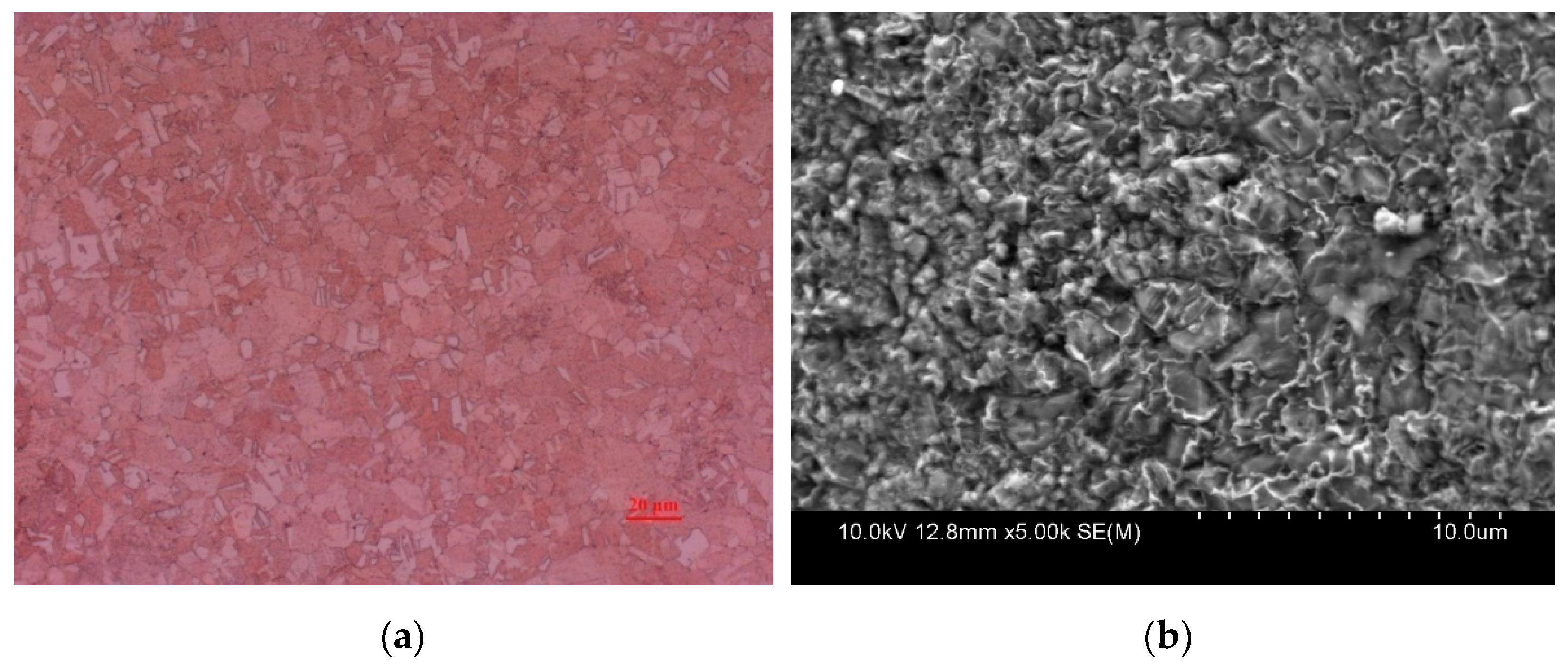
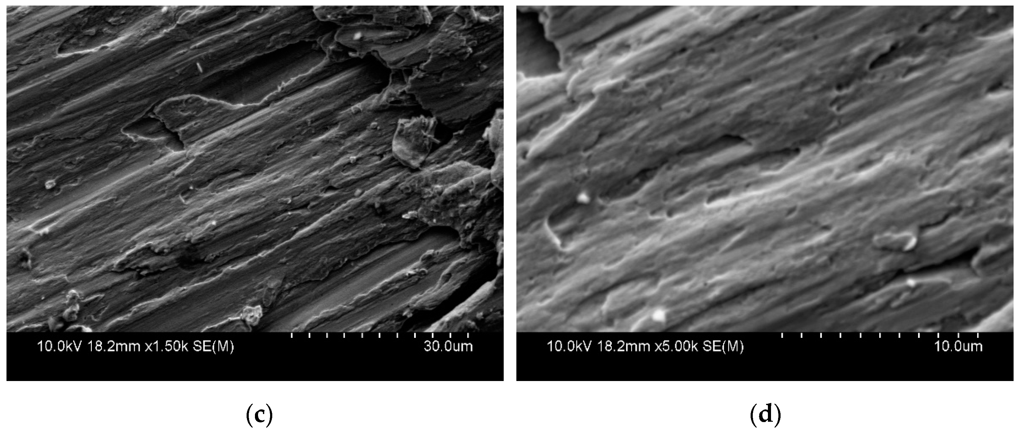
Figure 4 compares the microstructures in the original liner and recovered residual of the copper liner. The liner’s original microstructure is shown in Figure 4a,b. The average diameter of grain varies from 3 μm to 5 μm with equiaxed crystal structure, which are uniformly distributed. In Figure 4c,d, the stretched grain structure, dimples, and slip surfaces can be observed. The length of the grain can be longer than 30 μm and the length of plastic deformation zone can be 30–50 μm. The grain size has grown with the adjustment of grain boundaries, which means it has experienced tremendous plastic deformation and dynamic recrystallization occurs. The ductile fracture surface observed in Figure 4 can be summarized as dimple fracture and be used as assertive evidence to explain the dynamic macroscopic response of the copper liner under explosive loading.
With the characteristics of dynamic recrystallization and ductile fracture surface observed in the copper liner in Figure 4, it can be concluded that the copper liner has the ability to sustain a large amount of plastic deformation without rupture in the forming process of an EFP under explosive loading.

3.2. Tungsten Heavy Alloy Liners

Figure 5 presents the microstructures of the original liner and the retrieved residual of the 90W–9Ni–Co alloy after explosive loading. As shown in Figure 5a, the tungsten particles and matrix can be observed in the two-phase compound. The average diameter of the tungsten particles is about 10~50 μm, and the tungsten particles are evenly distributed in the Ni–Co–W alloy. Moreover, the recrystallization and crystal twin can be observed, which indicate the grain growth of tungsten particles in the processing of manufacture. In Figure 5b, tungsten particles and the Ni–Co matrix, which is abnormally line-shaped with white color, can be observed. With no slip surface, cleavage steps are observed and only a small amount of plastic deformation occurs in the Ni–Co matrix. As the average diameter of the tungsten particles is about 2~5 μm, associated with cracks, it can be concluded that cleavage is the main mechanism in the microstructure evolution under explosive loading.
Figure 6 makes a comparison of microstructures between the original liner and retrieved residual of the W–25Re alloy. Being a solid solution, as shown in Figure 6a, the fibrous grains dominate in the original microstructure of the W–25Re alloy. After explosive loading, pores and cracks appear and the grains refine. The average diameter of the grain is about 5–10 μm in the recovered residual, as shown in Figure 6b,c. Slip surfaces with a small amount of plastic deformation occur in the fibrous grains. From the fracture surface, it can be inferred that though there is a small amount of plastic deformation, transgranular cleavage is the major cause of the fracture of the W–25Re alloy liner under explosive loading.
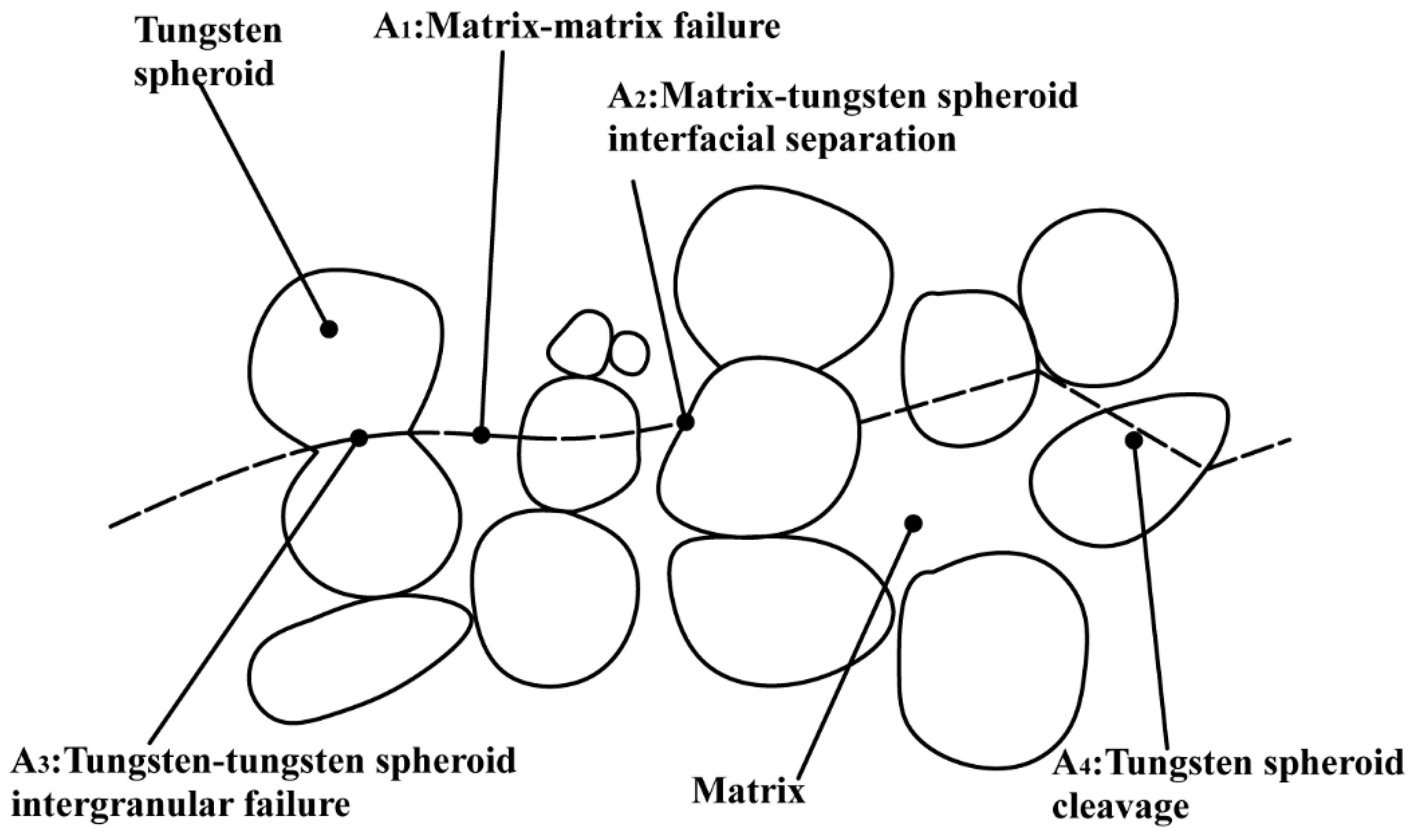
Figure 7 illustrates schematically the major modes of failure and anticipated fracture surface in tungsten alloys. Little evidence of a matrix is normally seen, and tungsten cleavage and interface failure are regularly observed.
The transgranular cleavage observed in fracture surfaces of the retrieved residual in Figure 5 and Figure 6 demonstrates that the fracture mode belongs to brittle fracture, which falls into the type A3 mode, as displayed in Figure 7. By comparing the microstructures of the original liner and retrieved residual of 90W–9Ni–Co and W–25Re alloys, it can be inferred: at high strain rates under explosive loading, both the W particles and matrix phase undergo tremendous deformation, and distortion of the W-grain network is more obvious, which could not satisfy the need of deformation in macroscopic scale. Micro-cracks occur in and around the W particles, which result in the transgranular cleavage of the W particles. Then, due to the severe stress concentration at the tip of the cracks, more cleavages of the W-grain arise, which further leads to the brittle fracture of the tungsten alloy under dynamic deformation [20,21,22,23].
In summary, the dynamic recrystallization and ductile fracture surface observed in the microstructure of copper explain the dynamic formation of a copper EFP under explosive loading, while the micro-cracks and cleavage observed in the 90W–9Ni–Co and W–25Re alloy which indicate the occurrence of brittle fracture are the predominant fracture mechanism and microstructure evolution of the two kinds of tungsten heavy alloy under explosive loading.

4. Numerical Simulation and Analysis

Due to the well-formed performance under explosive loading, copper EFP’s forming characteristics are analyzed in the numerical simulation. Then, associated with the stress and strain conditions under explosive loading, the fracture phenomenon of tungsten heavy alloys can be analyzed in the fracture mechanism.

4.1. Numerical Model of Copper EFP

As shown in Figure 8a, all of the components of the EFP charge structure are modelled with the 2D Lagrange algorithm in LS-DYNA. Central point initiation is deployed to initiate the explosive. The elements are axisymmetric solid-area weighted shell, with mesh size of about 0.5 mm per grid, and a half model symmetric of the y axis is carried out. The mesh is shown in the grid model of Figure 8b.
The material models of charge, casing, and liner are listed in Table 2. The behavior of the high-explosive charge is characterized by the Jones–Wilkins–Lee (JWL) equation of state and high-explosive-burn constitutive model, which are widely used to describe the pressure–volume relationship of the explosive. The JWL equation of state defines the pressure as [24,25]:
p = A ( 1 ω R 1 V ) e R 1 V + B ( 1 ω R 2 V ) e R 1 V + ω E V
where A, B, R1, R2, and ω are constants to describe the relationship between the pressure and the relative volume of the charge. The EOS parameters of explosive 8701 are listed in Table 3.
The selection of material model and setting of parameters of the liner are essential to predict the forming state of the copper EFP. In this paper, the Grüneisen equation of state is employed in conjunction with the Steinberg–Guinan constitutive model to simulate the forming of the copper EFP.
The Grüneisen EOS [26] can be used to describe how the materials interact with the shock wave and is based on Hugoniot’s relation between the vs. and the vp, as vs = c0 + svp, where vs. is the shock wave velocity, vp is the material particle velocity, c0 is the wave speed, and s is a material-related coefficient. The expression of equation of state of Grüneisen for compressed state is:
p = ρ 0 C 2 μ [ 1 + ( 1 γ 0 2 ) μ a 2 μ 2 ] [ 1 ( S 1 1 ) μ S 2 μ 2 μ + 1 S 3 μ 3 ( μ + 1 ) 2 ] + ( γ 0 + a μ ) E .
In the expanded state,
p = ρ 0 C 2 μ + ( γ 0 + a μ ) E
where C is the intercept of velocity curve between shock wave and particle, S1, S2, and S3 represent the slope of the vs-vp curve, γ0 is the coefficient of Grüneisen, and a is one-order correction of γ0. μ = ρ/ρ0 − 1 is a non-dimensional coefficient based on initial and instantaneous material densities. The parameters of equation of state are listed in Table 4.
The Steinberg–Guinan model [27] is available for modelling materials at very high strain rate (>105 s−1). The yield strength is a function of temperature and pressure. In the Steinberg–Guinan constitutive relation, the shear modulus, G, before the material melts, can be expressed as…
G = G 0 [ 1 + b p V 1 3 h ( E i E c 3 R 300 ) ] e f E i E m E i
where p is the pressure, V is the relative volume, and Ec is the cold compression energy:
E c ( x ) = 0 x p d x 900 R exp ( a x ) ( 1 x ) 2 ( γ 0 a 1 2 ) ,
x = 1 − V,
and Em is the melting energy:
E m ( x ) = E c ( x ) + 3 R T m ( x )
which is in terms of the melting temperature Tm(x):
T m ( x ) = T m 0 exp ( 2 a x ) V 2 ( γ 0 a 1 3 )
and the melting temperature at ρ = ρ0, Tm0.
The yield stress σy is given by:
σ y = σ 0 [ 1 + b p V 1 3 h ( E i E c 3 R 300 ) ] e f E i E m E i
when Em exceeds Ei, here σ0′is given by:
σ 0 = σ 0 [ 1 + β ( γ i + ε ¯ p ) ] n
where σ0 is the initial yield stress and γi is the initial plastic strain. If the work-hardened yield stress σ0′ exceeds σm, σ0′ is set to σm. After the melting point, σy and G are set to one half their initial value. the material parameters of the Steinberg–Guinan model for the copper liner are presented in Table 5.
The steel casing adopts the Grüneisen EOS and Johnson–Cook constitutive model. The Johnson–Cook model [28,29] is a widely used constitutive model which incorporates the effect of strain rate dependent work hardening and thermal softening. The Johnson–Cook constitutive relation is given by:
σ = ( σ 0 + B ε n ) ( 1 + C ln ε ˙ ε ˙ 0 ) ( 1 T m )
where ε is the plastic strain and the temperature factor is expressed as:
T = T T r T m T r
where Tr is the room temperature, and Tm is the melt temperature of the material. σ0, B, n, C, and n are material-related parameters. The material parameters of steel #45 for casing are presented in Table 6.

4.2. Numerical Results of Copper EFP

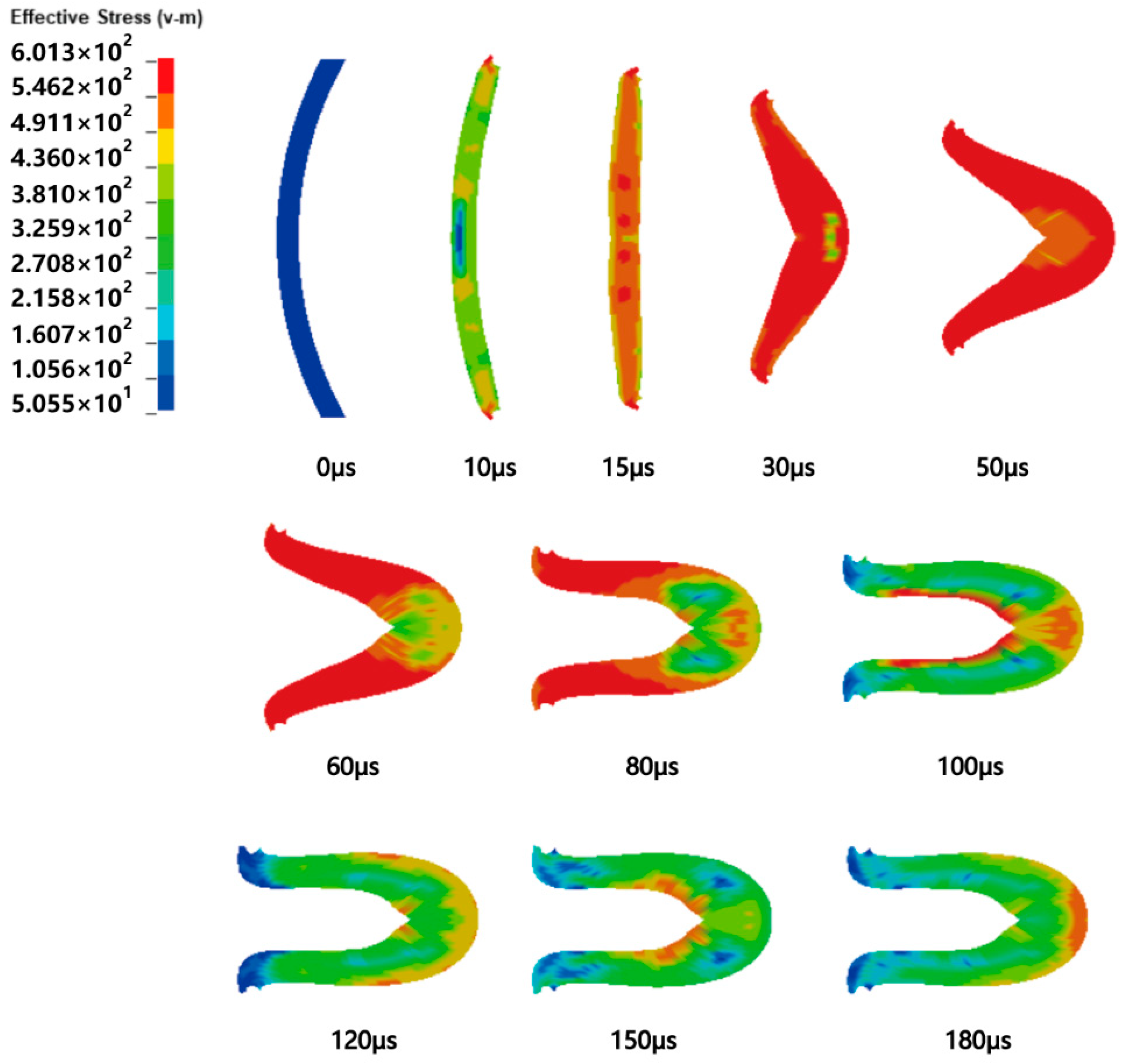
Figure 9 shows the shape and effective stress of the copper EFP at typical time in the forming stage. In the first 30 μs after the detonation of the charge, the detonation wave is transmitted to the top of the liner first. Thus, the top part of the liner accelerates and deforms in axial direction. As it interacts with the detonation wave, other parts of the liner deform and accelerate in sequence, with the bottom of the liner deforming last, which can be seen around 50 μs. At the same time, the liner is driven by the detonation wave to move forward along the axial direction. Then, due to the velocity gradient in the head and tail of the liner, the liner flips, and the inner surface of the liner will squeeze or even collide, which can be observed from 50 μs to 80 μs. The extrusion of the liner makes the inner wall of the liner close to the axis to form a rod-shaped projectile. After 80 μs, the shape of the EFP is basically stable.
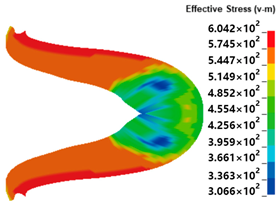
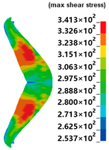
As shown in Table 7, the maximum von Mises stress can be as much as 604 MPa at 68 μs, and the maximum shear stress can reach 341 MPa. The maximum plastic strain reaches 2.71 after 100 μs. So, it can be concluded that in the forming stage of the copper EFP, the liner undergoes maximum shear stress and maximum effective stress in the early 70 μs, and the maximum plastic strain can be as much as 3.0.
Table 8 makes a comparison of numerical simulation and experiment results. L and D are the length and diameter of EFP, and L/D is the length to diameter ration of EFP. By the comparison of length, diameter, and length to diameter ratio, the numerical simulation results agree well with the experiment results, which verify the accuracy of the numerical simulation.
In conclusion, a feasible EFP liner should sustain tremendous stress in the early stage of forming without breaking. The liner has to bear large plastic strain under explosive loading, and undergo severe plastic deformation in the forming. Associated with the maximum stress and strain conditions in forming of EFP under explosive loading, the fracture phenomenon of tungsten heavy alloys can be analyzed in the fracture mechanism.

4.3. Analysis of Fracture Mechanism

In fracture mechanics, there are three modes of loading relative to a crack, as shown in Figure 10. Mode I is also called the opening mode, where the principal load is applied normally to the crack plane, which tends to open the crack. Mode II tends to slide one crack face with respect to the other. Mode III is called the tearing mode, which refers to out of plane shear [30]. On the microscopic scale, according to the feature of the fracture surface, the cleavage pattern is mainly produced by the tensile stress and results in the brittle fracture by separation (cleavage) across well-defined habit crystallographic planes [31]. As Mode I is the most dangerous loading pattern among the three modes, the stress field ahead of a crack tip in the opening mode is used to analyze the fracture mechanism of tungsten heavy alloys.
Figure 11 presents the definition of the coordinate axis ahead of a crack tip. σij and τij are the stress tensor. r and θ are the defined polar coordinate axis with the origin at the crack tip. KI denotes the stress intensity factor, and ν is Poisson’s ration. The stress fields ahead of a crack tip in an isotropic linear elastic material can be written in the form of (13) as an isotropic linear elastic material [32,33,34].
{ σ x x = K I 2 π r cos θ 2 ( 1 sin θ 2 sin 3 θ 2 ) σ y y = K I 2 π r cos θ 2 ( 1 + sin θ 2 sin 3 θ 2 ) τ x y = K I 2 π r sin θ 2 cos θ 2 cos 3 θ 2 σ z z = 0 ( Plane stress ) σ z z = υ ( σ x x + σ y y ) ( Plane strain ) τ x z = τ y z = 0
According to the von Mises criterion, yielding occurs when σe = σYS, the uniaxial yield strength. For plane stress or plane strain conditions, the principal stresses can be computed from the two-dimensional Mohr’s relationship:
σ 1 , σ 1 = σ x x + σ y y 2 ± [ ( σ x x σ y y 2 ) 2 + τ x y 2 ]
For plane stress σ3 = 0, and σ3 = ν(σ1 + σ2) for plane strain. Then,
{ σ 1 = K I 2 π r cos θ 2 ( 1 + sin θ 2 ) σ 2 = K I 2 π r cos θ 2 ( 1 sin θ 2 ) σ 3 = 0 ( Plane stress ) σ 3 = K I 2 π r cos θ 2 ( Plane strain )
By substituting the equations into:
σ e = 1 2 [ ( σ 1 σ 2 ) 2 + ( σ 1 σ 3 ) 2 + ( σ 2 σ 3 ) 2 ] 1 / 2
setting σe = σYS, and solving for r as a function of θ for plane stress:
r ( θ ) = K I 2 2 π σ s 2 cos 2 θ 2 ( 1 + 3 sin 2 θ 2 )
And for the plane strain,
r ( θ ) = 1 2 π ( K I σ s ) 2 cos 2 θ 2 ( ( 1 2 ν ) 2 + 3 sin 2 θ 2 )
where set ν = 0.3 for metal materials.
Fracture toughness KIC and damage tolerance dy of the three kinds of materials are listed in Table 9. The fracture toughness of copper is much higher than 90W–Ni–Co and W–25Re. The maximum fracture toughness of copper can reach 100 MPam1/2, while the maximum value of tungsten alloy can just reach 60 MPam1/2. The values of KIC for 90W–Ni–Co and W–25Re almost stay the same. dy, diameter of the process-zone at a crack tip, which indicates the damage tolerance of the plastic zone, are listed in the Table 9. dy of the copper ranges from 1 mm to 1000 mm, while damage tolerance of 90W–9Ni–Co and W–25Re varies from 0.1 mm to 1 mm.
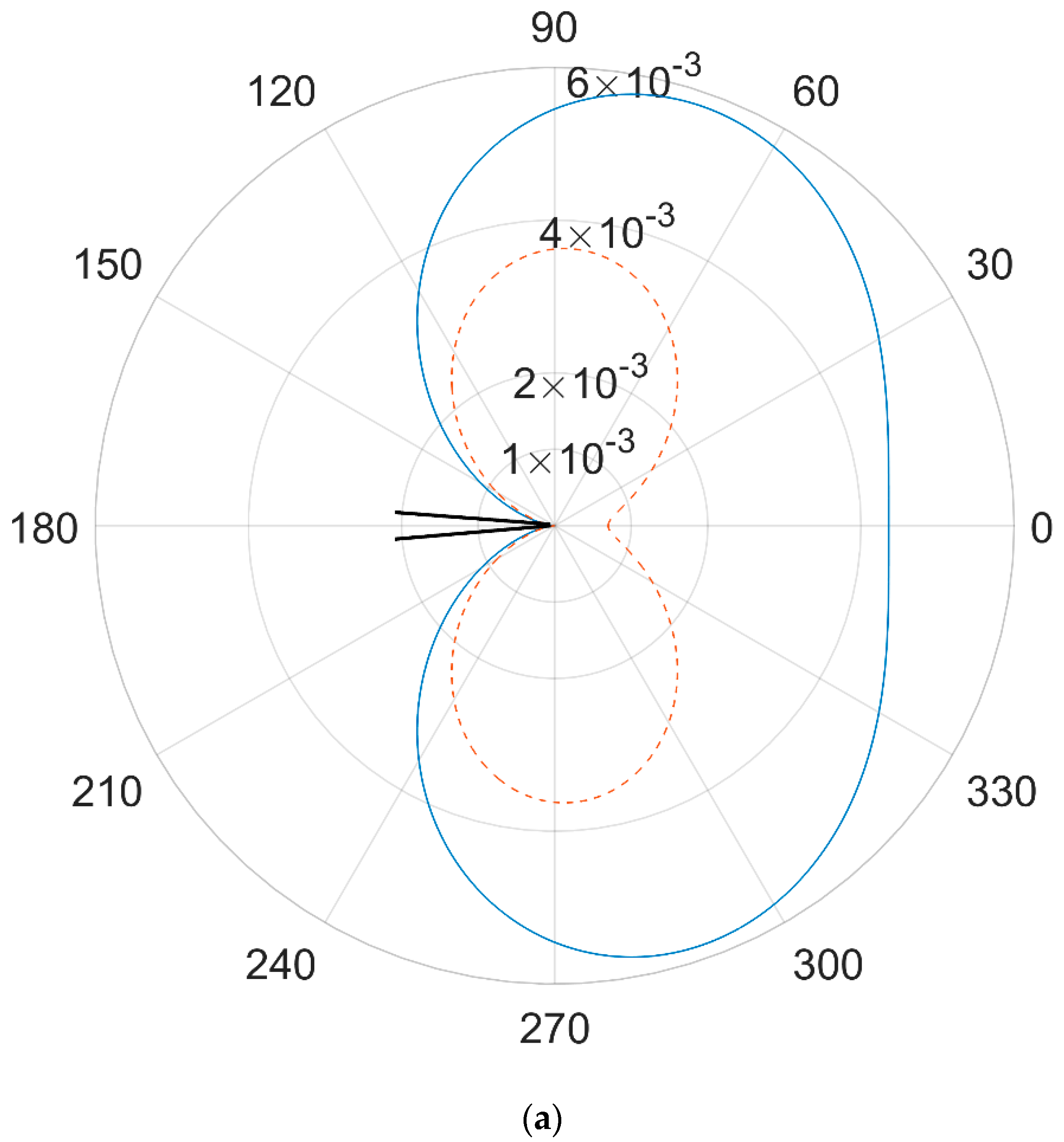
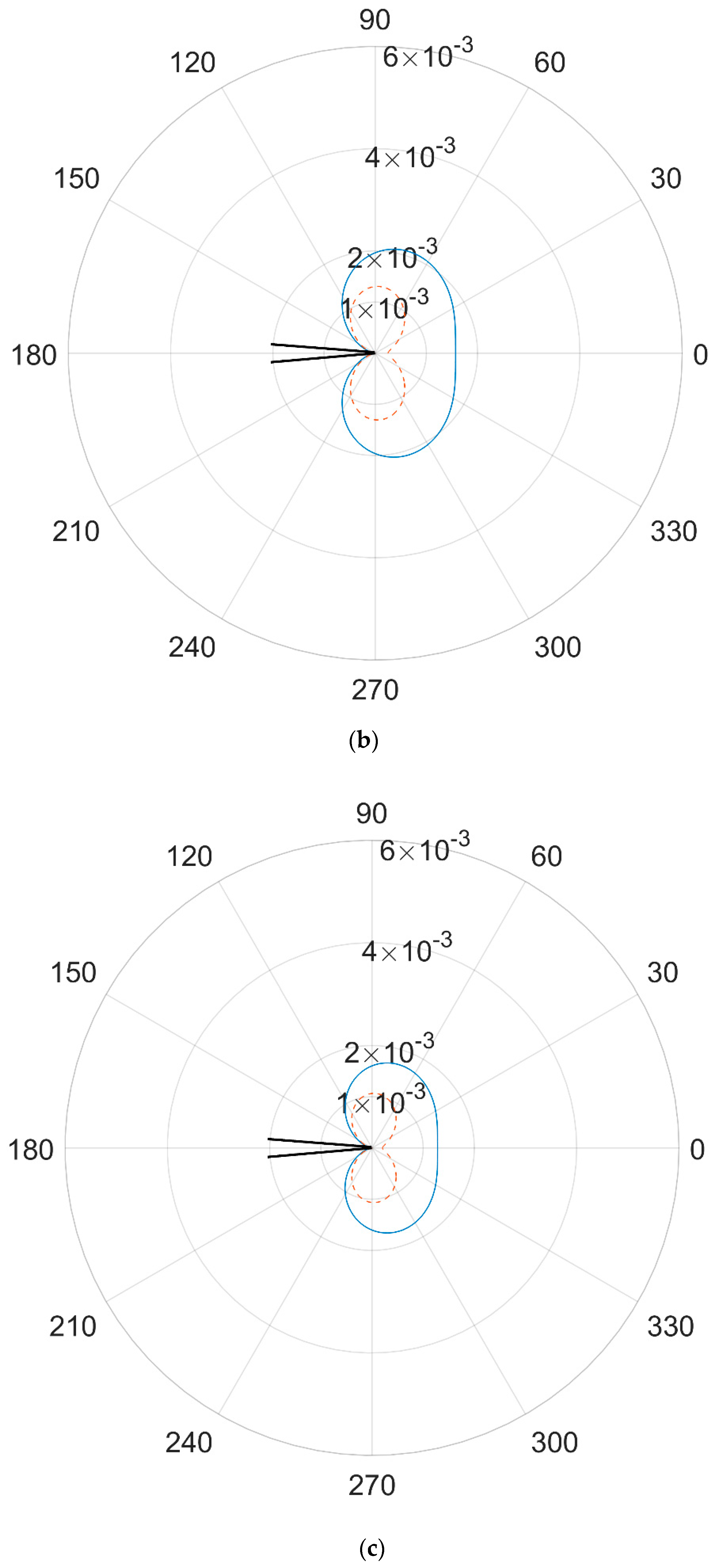
The lower values of fracture toughness and damage tolerance of 90W–9Ni–Co and W–25Re can be a convincing evidence to explain the fracture phenomenon in the flash X-ray experiment, but more detailed discussion should be given. By substituting the maximum values of stress and the fracture toughness of the three kinds of materials in Equation (17) and Equation (18), the crack-tip plastic zone shapes estimated from the elastic solutions and the von Mises yield criterion for Mode I of loading can be obtained, as shown in Figure 12. The solid line is for the plane stress zone, while the dashed line is for the plane strain.
As presented in Figure 12, the plain strain condition suppresses yielding, resulting in a smaller plastic zone when compared with the plain stress. The maximums of r(θ) for the three kinds of materials are listed in Table 10. For the plane stress condition, the maximum r(θ) for plane stress can reach 58 mm for copper, while for the plane strain, the value could only reach 36 mm. For the tungsten alloy, the values of r(θ) are much lower than copper. The maximum r(θ) is about 17~21 mm, while for plane strain the values reduce to 1 mm. The maximum of r(θ) for the plane strain of tungsten alloys is consistent with the values of dy, which indicates the damage tolerance of the plastic zone.
In conclusion, the crack-tip plastic zones of 90W–9Ni–Co and W–25Re are much smaller than copper. As the plain strain is the most dangerous condition in the fracture mode, it has more reference significance to understand the fracture mechanism of tungsten alloys. Under explosive loading with severe stress and strain conditions, cracks may occur inside the material. Then, due to the severe stress concentration at the tip of the cracks, it is easy for the cracks to propagate and trigger the cleavage in tungsten alloys. In Figure 5 and Figure 6, cracks and pores are easily observed, which are consistent with the prediction of the crack-tip plastic zone. While for copper with excellent ductility, it has the ability to bear a considerable amount of plastic deformation. In addition, it will not fracture even with cracks due to its big enough crack-tip plastic zone, as shown in Figure 12a.
In addition, the material selection criteria of the EFP liner can be further enriched and specified based on the value of r(θ) for the plane stress. The material selection criteria of the EFP liner can be summarized as below: (i) the most potential candidate of material should have fracture toughness KIC be of 70–150 MPam1/2, diameter of the process zone dy be of 10–1000 mm. (ii) Impact toughness αk can be an alternative guideline, which should be in the range of 1500–2000 KJm−2. (iii) Fracture surface appearance of microvoid coalescence both in the quasi-static and dynamic failure is preferred [19]. (iv) r(θ) of the crack-tip plastic zone can also be an alternative guideline to explain the fracture phenomenon in explosive loading. The potential candidate of an EFP liner should have a crack-tip plastic zone r(θ) as much as 58 mm for plane stress, and reach 36 mm for the plane strain condition. Then, the material could have the ability to sustain tremendous plastic deformation in the forming under explosive loading and form an EFP like copper.
5. Conclusions

(1)
Compared with Cu, 90W_9Ni_Co and W_25Re as two kinds of typical tungsten heavy alloy, are tested in the flash X-ray experiment to study their dynamic response under explosive loading. However, there are tremendous differences among the forming state and the penetration results of the three metal materials when used as an EFP liner.
(2)
The copper liner could form a coherent EFP with a moderate penetration depth in the steel target, while the 90W–9Ni–Co liner broke into discrete fragments and the W–25Re liner turned over at first and fractured into three parts later. As the fracture states in the forming phase, the penetration depth was much lower than the copper liner.
(3)
The microscopic features were examined to analyze the microstructure evolution of the dynamic response of the three metal materials: (i) in the copper liner, dynamic recrystallization occurs and the microstructure has experienced tremendous plastic deformation, which means copper as a validated EFP liner has the ability to bear extensive plastic deformation without break under explosive loading. (ii) In the 90W–9Ni–Co and W–25Re alloys liner, the cleavage observed in the fracture surface indicates the brittle fracture occurrence in the forming, belonging to type A3 mode, which means it is easy for the cracks to propagate and trigger the cleavage of W particles in the tungsten heavy alloys.
(4)
Copper EFP’s forming characteristics are analyzed in the numerical simulation to obtain the stress and strain conditions in forming of EFP under explosive loading. The maximum von Mises stress can be as much as 604 MPa, while the maximum shear stress can reach 341 MPa. In addition, the maximum plastic strain reaches 2.71. Associated with the maximum stress and strain conditions, the fracture mechanism of tungsten heavy alloys under explosive loading can be obtained.
(5)
In the plane stress state, the crack-tip plastic zones of 90W–9Ni–Co and W–25Re reach 21 mm and 17 mm, respectively. While in the plane strain state, the value of r(θ) of the crack-tip plastic zone of 90W–9Ni–Co and W–25Re are around 1mm. By comparison, the crack-tip plastic zones of 90W–9Ni–Co and W–25Re are much smaller than copper, under explosive loading with severe stress and strain conditions, cracks may occur inside the material. Then, due to the severe stress concentration at the tip of the cracks, it is easy for the cracks to propagate and trigger the cleavage in tungsten alloys.
(6)
The value of r(θ) of the crack-tip plastic zone can be used to explain the fracture phenomenon in explosive loading, which can be an alternative guideline for material selection criteria of the EFP liner. The potential candidate of an EFP liner should have a crack-tip plastic zone r(θ) as much as copper. For a feasible EFP liner, the crack-tip plastic zone r(θ) should be as much as 58 mm for plane stress, and reach 36 mm for plane strain condition.
The research work not only makes an attempt to study the dynamic response of typical tungsten heavy alloys under explosive loading, but to also provide an identification method associated to microcosmic scale with fracture mechanics to determine whether or not the alloy materials are capable of being used to form a coherent EFP. The research results are significant in understanding the dynamic forming, microstructure evolution, and fracture mechanism of tungsten heavy alloys.

Author Contributions

Methodology, validation, writing—original draft preparation, funding acquisition, L.D.; writing—review and editing, supervision, project administration, P.S.; data curation, resources, L.J. All authors have read and agreed to the published version of the manuscript.

Funding

This work was supported by the National Natural Science Foundation of China (Grant No. 11802142) and a project of the State Key Laboratory of Explosion Science and Technology (Grant No. KFJJ20-08M).

Institutional Review Board Statement

Not applicable.

Informed Consent Statement

Not applicable.

Data Availability Statement

The raw and processed data generated during this study will be made available upon reasonable request.

Acknowledgments

The authors thank the National Natural Science Foundation of China (Grant No. 11802142) and project of the State Key Laboratory of Explosion Science and Technology (Grant No. KFJJ20-08M).

Conflicts of Interest

The authors declare no conflict of interest.

References

  1. Walters, W.P.; Zukas, J.A. Fundamentals of Shaped Charges; John Wiley: Hoboken, NJ, USA, 1989. [Google Scholar]
  2. Sui, S.; Wang, S. Terminal Effects; National Defense Industry Press: Beijing, China, 2000.
  3. Wang, S. Terminal Effects, 2nd ed.; China Science Publishing & Media Ltd.: Beijing, China, 2019. [Google Scholar]
  4. Pappu, S.; Murr, L.E. Hydrocode and microstructural analysis of explosively formed penetrators. J. Mater. Sci. 2002, 37, 233–248. [Google Scholar] [CrossRef]
  5. Held, M. Liners for shaped charges. J. Battlef. Technol. 2001, 4, 1–6. [Google Scholar]
  6. Lassner, E.; Schubert, W.D. Tungsten: Properties, Chemistry, Technology of the Element, Alloys, and Chemical Compounds; Springer: Berlin/Heidelberg, Germany, 1999. [Google Scholar]
  7. Patrik, A.; Patrik, L. Penetration performance of a calibre 5.56 mm Tungsten-Rhenium AP-Projectile into steel and ceramic targets. In Proceedings of the 29th International Symposium on Ballistics, Edinburgh, UK, 9–13 May 2016. [Google Scholar]
  8. Prasad, B.L.; Annamalai, A.R. Effect of Rhenium addition on tungsten heavy alloys processed through spark plasma sintering. Ain Shams Eng. J. 2021, 12, 2957–2963. [Google Scholar] [CrossRef]
  9. Guo, W.; Li, S.K.; Wang, F.C.; Wang, M. Dynamic recrystallization of tungsten in a shaped charge liner. Scr. Mater. 2009, 60, 329–332. [Google Scholar] [CrossRef]
  10. Mutoh, Y.; Ichikawa, K.; Nagata, K.; Takeuchi, M. Effect of rhenium addition on fracture toughness of tungsten at elevated temperatures. J. Mater. Sci. 1995, 30, 770–775. [Google Scholar] [CrossRef]
  11. Sadat, T.; Hocini, A.; Lilensten, L.; Faurie, D.; Tingaud, D.; Dirras, G. Data on the impact of increasing the W amount on the mass density and compressive properties of Ni–W alloys processed by spark plasma sintering. Data Brief 2016, 7, 1405–1408. [Google Scholar] [CrossRef] [PubMed] [Green Version]
  12. Stawovy, M.T. Single Phase Tungsten Alloy. 2005. Available online: https://www.freepatentsonline.com/7360488.html (accessed on 17 December 2021).
  13. Stawovy, M.T. Single Phase Tungsten Alloy for Shaped Charge Liner. 2005. Available online: https://www.freepatentsonline.com/y2005/0241522.html (accessed on 17 December 2021).
  14. Rolc, S.; Buchar, J.; Akstein, Z. Computer simulation of Explosively formed projectiles (EFP). In Proceedings of the 23rd International Symposium on Ballistics, Tarragona, Spain, 16–20 April 2007; pp. 185–192. [Google Scholar]
  15. Bingol, C.G.; Yildirim, R.O. Investigation of the effect of thickness and radius of curvature on explosively formed penetrators(EFP) formation. In Proceedings of the 25th International Symposium on Ballistics, Beijing, China, 17–21 May 2010; pp. 821–828. [Google Scholar]
  16. Li, W.B.; Wang, X.M.; Zhou, H. Effect of the liner material on the shape of dual mode penetrators. Combust. Explos. Shock. Waves 2015, 51, 387–394. [Google Scholar] [CrossRef]
  17. Wang, Y.J.; Li, W.B.; Li, W.B.; Wang, X.M.; Xu, H.Y. Influence of structural characteristics on EFP formation under different liner materials. In Proceedings of the 31th International Symposium on Ballistics, Hyderabad, India, 4–8 November 2019. [Google Scholar]
  18. Koch, R.P.; Snyder, J.; Fong, R.; Redner, P.; Sadangi, R.; Kapoor, D. Using Nickel-Tungsten Alloys to Produce Multiple Explosively Formed Penetrator (MEFP) Warheads. In Proceedings of the 30th International Symposium on Ballistics, Long Beach, CA, USA, 11–15 September 2017. [Google Scholar]
  19. Ding, L.; Jiang, J.; Men, J.; Wang, S.; Li, M. Research on Feasibility of Several High Density Materials for EFP Liner and Material Selection Criteria. Propellants Explos. Pyrotech. 2017, 42, 360–369. [Google Scholar] [CrossRef]
  20. Lea, C.; Muddle, B.C.; Edmonds, D.V. Segregation to interphase boundaries in liquid-phase sintered tungsten alloys. Metall. Trans. A 1983, 14, 667–677. [Google Scholar] [CrossRef]
  21. Edmonds, D.V. Structure/property relationships in sintered heavy alloys. Int. J. Refract. Met. Hard Mater. 1991, 10, 15–26. [Google Scholar] [CrossRef]
  22. Kim, D.K.; Lee, S.; Noh, J.W. Dynamic and quasi-static torsional behavior of tungsten heavy alloy specimens fabricated through sintering, heat-treatment, swaging and aging. Mater. Ence Eng. A 1998, 247, 285–294. [Google Scholar] [CrossRef]
  23. Fan, J. Wu He Jin Ji Qi Zhi Bei Xin Ji Shu; Metallurgical Industry Press: Beijing, China, 2006. [Google Scholar]
  24. Hallquist, J. LS-DYNA Keyword User’s Manual, Version 970. 2003. Available online: https://www.dynasupport.com/manuals/ls-dyna-manuals/ls-dyna-970-manual-for-keyword-format (accessed on 17 December 2021).
  25. Hallquist, J.O. LS-Dyna Theory Manual. 2006. Available online: https://www.dynasupport.com/manuals/additional/ls-dyna-theory-manual-2005-beta/view (accessed on 17 December 2021).
  26. Andre, M.M. Dynamic Behavior of Materials; John Wiley & Sons: Hoboken, NJ, USA, 1994. [Google Scholar]
  27. Steinberg, D.J. Equation of State and Strength Properties of Selected Materials; Lawrence Livermore National Laboratory: Livermore, CA, USA, 1991.
  28. Johnson, G.R. A constitutive model and data for metals subjected to large strains, high strain-rates and high temperatures. In Proceedings of the Seventh International Symposium on Ballistics, Hague, The Netherlands, 19–21 April 1983; p. 541. [Google Scholar]
  29. Johnson, G.R.; Cook, W.H. Fracture characteristics of three metals subjected to various strains, strain rates, temperatures, and pressres. Eng. Fract. Mech. 1985, 21, 31–48. [Google Scholar] [CrossRef]
  30. Kundu, T. Fundamentals of Fracture Mechanics; Taylor & Francis Group: Abingdon, UK, 2008. [Google Scholar]
  31. Chen, J.H.; Cao, R. Micromechanism of Cleavage Fracture of Metals: A Comprehensive Microphysical Model for Cleavage Cracking in Metals; Butterworth-Heinemann: Oxford, UK, 2014. [Google Scholar]
  32. Anderson, T.L. Fracture Mechanics: Fundamentals and Applications; Taylor & Francis Group: Abingdon, UK, 1991. [Google Scholar]
  33. Jin, C.; Shushan, Z. Fracture Mechanics; Science Press: Beijing, China, 2006. [Google Scholar]
  34. Perez, N. Fracture Mechanics; Kluwer Academic Publishers: Dordrecht, The Netherlands, 2004. [Google Scholar]
  35. Ashby, M.F. Materials Selection in Mechanical Design Third Edition. MRS Bull. 2005, 30, 995. [Google Scholar]
  36. Gludovatz, B.; Faleschini, M.; Wurster, S.; Hoffmann, A.; Pippan, R. Influence of microstructure on the fracture toughness of tungsten alloys. In Proceedings of the Minerals, Metals & Materials Society (TMS) Annual Meeting, New Orleans, LA, USA, 9–13 March 2008. [Google Scholar]
  37. Gludovatz, B.; Wurster, S.; Hoffmann, A.; Pippan, R. Fracture toughness of polycrystalline tungsten alloys. Int. J. Refract. Met. Hard Mater. 2010, 28, 674–678. [Google Scholar] [CrossRef]
Figure 1. EFP charge structure. (a) 2D geometric sketch. (b) 3D geometric sketch. (c) Components structure. (d) Assembly structure.
Crystals 12 00154 g001
Figure 2. Schematic diagrams of the flash X-ray experiment of a typical EFP.
Crystals 12 00154 g002
Figure 3. X-ray photographs of liners for different metal materials in the experiment. (a) Copper. (b) 90W–9Ni-Co. (c) W–25Re.
Crystals 12 00154 g003
Figure 4. Comparison of microstructures in the original and recovered copper liner. (a) Original structure captured by metalloscope. (b) Original structure captured by SEM. (c) Fracture surface of recovered residual. (d) Enlarged view of fracture surface.
Crystals 12 00154 g004aCrystals 12 00154 g004b
Figure 5. Microstructures in recovered 90W–9Ni–Co alloy liner. (a) Original structure captured by metalloscope. (b) Crack distribution on the fracture surface. (c) Crack pattern around tungsten particles.
Crystals 12 00154 g005aCrystals 12 00154 g005b
Figure 6. Comparison of microstructures in the original and recovered W–25Re alloy liner. (a) Original structure captured by metalloscope. (b) Microstructure of retrieved residual. (c) Fracture surface of retrieved residual.
Crystals 12 00154 g006aCrystals 12 00154 g006b
Figure 7. Schematic illustration of major failure modes in tungsten alloys. A1: ductile transgranular fracture of matrix phase; A2: intergranular fracture of matrix phase; A3: transgranular cleavage of W-grains; A4: intergranular fracture of W-grain network; A5: tungsten side of W-matrix interface fracture; A6: matrix side of W-matrix interface fracture.
Crystals 12 00154 g007
Figure 8. Numerical and grid model of EFP charge structure. (a) Diagram of numerical model. (b) Grid model.
Crystals 12 00154 g008
Figure 9. Effective stress of the copper EFP at typical time after detonation.
Crystals 12 00154 g009
Figure 10. Three modes of loading relative to a crack: mode I (opening mode), mode II (shear or sliding mode), and mode III (tearing mode).
Crystals 12 00154 g010
Figure 11. Definition of the coordinate axis ahead of a crack tip.
Crystals 12 00154 g011
Figure 12. Crack-tip plastic zone shapes estimated. (a) Copper. (b) 90W-9Ni-Co. (c) W-25Re.
Crystals 12 00154 g012aCrystals 12 00154 g012b
Table 1. Parameters of three kinds of metal materials for EFP liner.
MaterialsDensity ρ/g·cm−3Melting Point Tm/°CElongation
δ/%
Yield Stress
σs/MPa
Tensile Stress
σb/MPa
Copper8.96135630–40120245–315
90W–9Ni–Co17.10320035600930
W–25Re19.50310015–18/1600–1950
Table 2. Material models used in numerical simulation.
ComponentsMaterialDensity ρ (g/cm3)Equation of StateConstitutive Model
Charge87011.71Jones–Wilkins–LeeHigh–Explosive–Burn
CasingSteel #457.83GrüneisenJohnson–Cook
LinerOFHC8.96GrüneisenSteinberg–Guinan
Table 3. JWL EOS parameters of explosive 8701.
ExplosiveD (m/s)A (GPa)B (GPa)R1R2ωE0 (J·mm−3)
87018315881.4510.4594.801.00.320.087
Table 4. EOS parameters of the copper liner.
MaterialGrüneisen CoefficientC (m/s)S1S2a
OFHC2.0234901.48900.47
Table 5. Material parameters of the Steinberg–Guinan model for the copper liner.
ρ (g/cm3)G0 (MPa)σ0 (MPa)βnγiσmb
8.9647,700120360.45064036
bhfTm0(K)γ0aPCSPALL
0.450.0003770.00117902.021.5−93
Table 6. Material parameters of steel #45 for casing.
Materialρ(g/cm3)Grüneisen CoefficientC(m/s)S1S2a
Steel #457.832.0234901.48900.47
σ0 (MPa)B (MPa)nCmTm (K)
1753800.320.0061.01793
Table 7. Maximum stress and strain conditions in the forming of the Copper EFP.
CharacteristicsTime (μs)Forming ShapeMaximum Value
von Mises Stress68 Crystals 12 00154 i001604 MPa
Shear Stress32 Crystals 12 00154 i002341 MPa
Plastic Strain≥100 Crystals 12 00154 i0032.74
Table 8. Comparison of the copper EFP’s forming states in numerical simulation and the experiment results.
Forming ShapeL/CDD/CDL/D
Numerical Simulation Crystals 12 00154 i0040.6720.3721.81
Experimental Result Crystals 12 00154 i0050.6170.3291.88
Table 9. Fracture toughness KIC and damage tolerance dy of the three kinds of materials.
MaterialKIC (MPam1/2)dy (mm)Fracture ModeReference
Copper79–1001–1000Dimple[35]
90W–9Ni–Co55–600.1–1Cleavage[35]
W–25Re54.20.1–1Cleavage[36,37]
Table 10. The maximum of r(θ) for the three kinds of materials.
MaterialMaximum of r(θ)/mm
Plane StressPlane Strain
Copper5836
90W–9Ni–Co211
W–25Re171
Publisher’s Note: MDPI stays neutral with regard to jurisdictional claims in published maps and institutional affiliations.