Abstract
In order to increase the penetration ability of tungsten fiber-reinforced Zr-based bulk metallic glasses matrix composite rod, two multi-diameter tungsten fiber-reinforced Zr-based bulk metallic glasses matrix composites (MD-WF/Zr-MG) are designed. In MD-WF/Zr-MG-I, the diameters of tungsten fiber (WF) increase gradually from the inside to outside, which is the opposite in MD-WF/Zr-MG-II. Penetration experiment of two kinds of MD-WF/Zr-MG rods into rolled homogeneous armor (RHA) steel target from 1470 m/s to 1630 m/s is conducted. The average penetration depth of the MD-WF/Zr-MG-II rod is higher than that of the MD-WF/Zr-MG-I rod. Penetration failure modes of MD-WF/Zr-MG-I and MD-WF/Zr-MG-II rods are bending, backflow of WFs and shear failure respectively. The failure mode of MD-WF/Zr-MG is affected by the bend spaces and the ultimate bending diameters of WFs. If the bend spaces of all WFs are equal or larger than their ultimate bending diameters, the penetration failure mode is the bending and backflow of WFs, oppositely the penetration failure mode is the shear failure. The MD-WF/Zr-MG rod with shear failure exhibits high penetration ability because of low penetration resistance and little residual material in the crater. When designing MD-WF/Zr-MG, bend spaces of a part of WFs should be smaller than their ultimate bending diameter to cause shear failure.
1. Introduction
Tungsten fiber-reinforced Zr-based bulk metallic glasses matrix composite (WF/Zr-MG) is a kind of unidirectional fiber-reinforced composite with tungsten fiber (WF) as the reinforcement phase and Zr-based bulk metallic glasses (Zr-MG) as the matrix [1,2]. WF/Zr-MG was firstly prepared by Dandliker et al. in 1998 [3]. Then researchers found that WF/Zr-MG was a potential penetrator material owing to advantageous properties. Firstly, there is little difference between the density of WF/Zr-MG and tungsten heavy alloy (WHA). When the volume fraction of WF in WF/Zr-MG is 80%, the density of WF/Zr-MG is more than 17.1 g/cm3 [4,5], and comparatively that of WHA is 17.6 g/cm3. Secondly, the compression strength of WF/Zr-MG is much higher than WHA. Normally, the quasi-static and dynamic compression strength of WF/Zr-MG is more than 1.8 GPa and 2.5 GPa, respectively [3,4,5,6,7,8,9,10,11,12,13,14,15]. In the research of Chen et al., the dynamic compressive strength of WF/Zr-MG even reached 3.5 GPa [15]. In contrast, the compression strength of WHA is about 1.2 GPa [16]. Moreover, WF/Zr-MG rods exhibited self-sharpening feature during the penetration experiments, which is similar with depleted uranium alloys. The diameter of the crater penetrated by WF/Zr-MG rods is about 15% lower than that of WHA rods [5,17]. Based on the advantageous properties of WF/Zr-MG, it exhibits high penetration ability. The penetration performance of WF/Zr-MG rods was about 10–20% higher than that of WHA rods under ideal penetration conditions [5,17,18,19,20,21]. However, WF/Zr-MG cannot be directly applied in an armor piercing projectile because its penetration performance is unstable. Chen et al. found that though the WF/Zr-MG rod can achieve effective penetration in the Q235 steel target, the WF/Zr-MG rod has no distinct advantage in the penetration performance compared with the WHA rod in 800~1000 m/s because of ballistic trajectory deflection [19]. Our previous research found that longitudinal splitting occurred in WF/Zr-MG rods with L/D of 3.75 during the penetration process, which resulted in a much lower penetration efficiency than that of WHA rods [17]. Therefore, research on covered material processing [6,22,23], experimental study [17,18,19,20,21], and numerical simulation [24,25,26] are conducted to analyze the causes and influencing factors of ballistic deflection and longitudinal splitting of WF/Zr-MG rods in order to improve its penetration stability.
The research results show that WF has a great influence on the strength, failure strain, and penetration behavior of WF/Zr-MG [8,9,27,28,29,30], especially the diameter of WF. Zhang et al. conducted systematic research on the influence of the diameter of WF on the compressive strength of composite materials [30]. The results showed that the diameter of WF has different effects on quasi-static compression and dynamic compression of composites. The compressive strength and fracture strain of WF/Zr-MG decrease with the increase of the diameter of WF. However, there is no linear relationship between the compressive strength of WF/Zr-MG and the diameter of WF during dynamic compression. Our previous research found that the diameter of tungsten fiber also has a great influence on the penetration behavior of composites. The penetration experiments of WF/Zr-MG reinforced by Ø0.3 mm, Ø0.5 mm, Ø0.7 mm, and Ø1.0 mm WFs were conducted respectively. The WF/Zr-MG rod reinforced by Ø0.3 mm WFs had the most stable penetration performance, and the WF/Zr-MG rod reinforced by Ø0.7 mm WFs had the deepest penetration depth [31]. As is seen, the diameter of WF has different effects on the quasi-static compression, dynamic compression, and penetration behavior of WF/Zr-MG, and WFs with different diameters have different advantages and disadvantages. Therefore, it is possible to make use of the advantages and avoid the disadvantages of WFs when WF/Zr-MG is reinforced by multiple diameter WFs. However, the research has not been studied up to now.
In this paper, two MD-WF/Zr-MG are designed and prepared. The penetration experiments of the two MD-WF/Zr-MG rods are conducted. According to the analysis of experimental results, the penetration ability and failure mode of the two WF/Zr-MG rods are revealed. A design method of MD-WF/Zr-MG with high penetration ability is also obtained according to the experimental results.
2. Design and Preparation of MD-WF/Zr-MG
Compared with homogeneous materials, such as WHA and depleted uranium alloys, WF/Zr-MG has the advantage of designability. The volume fraction and diameter of WFs in WF/Zr-MG can be changed according to the requirements. In our previous penetration experiments, WF/Zr-MG reinforced by Ø0.3 mm, Ø0.5 mm, Ø0.7 mm, and Ø1.0 mm WFs rods exhibit different advantages and disadvantages in penetration. Figure 1 shows the experimental results of our previous research [31]. Compared with the WHA rod, the WF/Zr-MG rod reinforced by Ø0.3 mm WFs had the most stable penetration performance, and the WF/Zr-MG rod reinforced by Ø0.7 mm WFs had the deepest penetration depth. In order to make full use of the advantages and avoid the disadvantages of these WF/Zr-MG rods, two multi-diameter tungsten fiber reinforced Zr-based bulk metallic glasses matrix composite (MD-WF/Zr-MG) are designed. In MD-WF/Zr-MG-I, the diameters of WF increase gradually from the inside to outside. On the contrary, the diameters of WF in MD-WF/Zr-MG-II decrease gradually from the inside to outside. The cross section of MD-WF/Zr-MG schematic is shown in Figure 2.
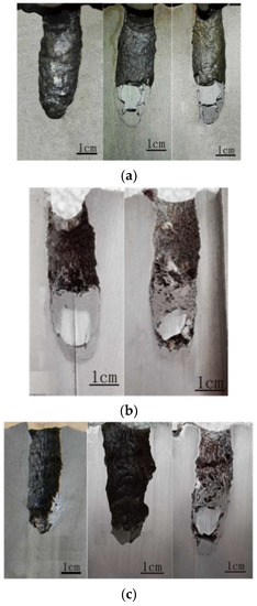
Figure 1.
Longitudinal section of the craters penetrated by (a) Tungsten heavy alloy (WHA) rods, (b) WF/Zr-MG rods reinforced by Ø0.3 mm WFs, and (c) WF/Zr-MG rods reinforced by Ø0.7 mm WFs [31].
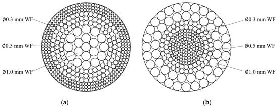
Figure 2.
Cross section of MD-WF/Zr-MG schematic: (a) MD-WF/Zr-MG-I and (b) MD-WF/Zr-MG-II.
Ingots of Zr41.25Ti13.75Ni10Cu12.5Be22.5 (in at. pct) were first prepared by combining the constitutive elements (purity 99.5 pct or higher) in an induction furnace under an argon atmosphere. WFs with a nominal diameter of 0.3 mm, 0.5 mm, and 1.0 mm were straightened. The fibers were cleaned in a bath of acetone through an ultrasonic method and then cleaned by ethanol. The WFs were placed in the sealed end of an evacuated quartz tube according to Figure 2. The ingots were then heated and melted in a resistive furnace, followed by pressure infiltration. The MD-WF/Zr-MG were prepared successfully using infiltration and rapid solidification. Figure 3 shows the cross sections of MD-WF/Zr-MG. The volume fractions of all the WFs and Ø1.0 mm WFs, Ø0.5 mm WFs, and Ø0.3 mm WFs in MD-WF/Zr-MG-I are 81.90 and 20.10%, and 40.22 and 21.57%, respectively. The volume fractions of all the WFs and Ø1.0 mm WFs, Ø0.5 mm WFs, and Ø0.3 mm WFs in MD-WF/Zr-MG-II are 81.16 and 46.14%, and 19.22 and 15.80%, respectively. The densities of MD-WF/Zr-MG-I and MD-WF/Zr-MG-II are 17.03 ± 0.05 g/cm3 and 16.90 ± 0.05 g/cm3, respectively.
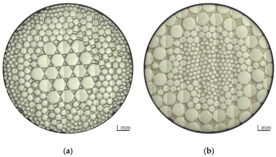
Figure 3.
Cross section of MD-WF/Zr-MG: (a) MD-WF/Zr-MG-I and (b) MD-WF/Zr-MG-II.
3. Experiment of MD-WF/Zr-MG Rod
3.1. Setup of Experiment
Figure 4 shows the MD-WF/Zr-MG rod and the assembly drawing of the projectile. The largest diameter of WFs in MD-WF/Zr-MG is Ø1.0 mm, so the rod with a diameter of 10 mm is prepared. In order to compare with the previous experimental results in reference [17], the rod with the same length is selected, so the length of the MD-WF/Zr-MG rod is set to 54 mm. A tail and a nose are installed in the bottom and top of the rod respectively to enhance the flight stability of the rod, as is seen in Figure 4a. Both the tail and nose are made of aluminum alloy to reduce their interference with penetration results. Since the diameter of the rod is less than that of the Ø25 mm smooth bore gun, a sub-calibre launching technique of a long rod is employed in the present paper. As shown in Figure 4b, the aluminum alloy sabots are used to fit the larger diameter of smooth bore for firing a smaller rod. A nylon block is used to push the projectile. A steel platen is placed between the rod and block to increase the strength of the block. Three rods of each material are manufactured. The mass of projectiles and rods are shown in Table 1. The target in the experiment is made of RHA with a thickness of Ø80 mm.
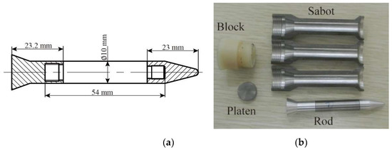
Figure 4.
(a) Dimension of MD-WF/Zr-MG rod and (b) assembly drawing of the projectile.

Table 1.
Mass of projectile and rod.
A Ø25 mm smooth bore artillery was used to launch the projectiles. The setup of the experiments is shown in Figure 5. The average impact velocities of rods between 2 and 4 m in front of the target are measured by a velocimeter. The speed range is also selected as in reference [17], which varies from 1470 to 1650 m/s.
Figure 5.
Setup of experiments.
3.2. Experimental Results and Analysis
Figure 6 shows experimental results of DOP vs the impact velocity of the MD-WF/Zr-MG-I and MD-WF/Zr-MG-II rods (the solid point in Figure 6). The dotted line shows the fitting curves of the experimental results. As shown in Figure 6, the average DOP of the MD-WF/Zr-MG-II rods is higher than that of the MD-WF/Zr-MG-I rods. According to the experimental results, the penetration ability of the MD-WF/Zr-MG-II rods is better than that of the MD-WF/Zr-MG-I rods.
Figure 6.
Experimental results of DOP of the MD-WF/Zr-MG-I and MD-WF/Zr-MG-II rods.
In order to reveal the penetration mechanism and the reason for the difference of penetration ability between MD-WF/Zr-MG-I rods and MD-WF/Zr-MG-II rods, their penetration craters were dissected. Figure 7 is the longitudinal sections of craters penetrated by MD-WF/Zr-MG-I rods. Figure 7 shows that the craters are vertical with no trajectory deflection, which proves that the stiffness of the WF/Zr-MG rod increases with the addition of larger diameter WFs, as trajectory deflection often occurs during the penetration experiments of WF/Zr-MG rods with small aspect ratio [17]. According to the measurement, the diameters of the three craters are 16.4, 17.2, and 17.9 mm, respectively. The average diameters of craters are smaller than that penetrated by WHA rods (about 19~20 mm [31]), which proves that the MD-WF/Zr-MG-I rods exhibit a self-sharpening feature during the penetration process.
Figure 7.
Longitudinal sections of craters penetrated by MD-WF/Zr-MG-I rods. (a) I-1 v = 1532.8 m/s. (b) I-2 v = 1544.0 m/s. (c) I-3 v = 1603.0 m/s.
Figure 8 shows the external view of the residual MD-WF/Zr-MG-I rods. Figure 8a is a front view of the residual rod in Figure 7a. As shown in Figure 8a, Ø1 mm WFs is on the outside of the residual rod, and Ø0.3 and Ø0.5 mm WFs are on the inside of the residual rod, which is opposite to the original MD-WF/Zr-MG-I rod. Figure 8b is a magnified view of the residual rod in Figure 7b. Figure 8b reveals the reason why the Ø1 mm WFs in Figure 8a is on the outside of the residual rod. Figure 8b shows that the WFs at the head of the rod turn out layer by layer, which results in the arrangement of WFs in the residual rod is opposite to that in the original rod. Figure 8 proves that the WFs at the head of the rod bending and backflow during the penetration process. This penetration failure mode of the MD-WF/Zr-MG-I rod is different from the adiabatic shear failure mode of depleted uranium alloys. The penetration failure mode of the MD-WF/Zr-MG-I rod leads to a hemispherical head, which is similar to that of WHA [16,32].
Figure 9 is the longitudinal sections of craters penetrated by MD-WF/Zr-MG-II rods. Similar to the craters penetrated by MD-WF/Zr-MG-I rods (Figure 7), the craters penetrated by MD-WF/Zr-MG-II rods are also vertical and exhibit self-sharpening feature during the penetration process (the average diameters of craters in Figure 9 are 17.3, 18.5, and 18.2 mm, respectively). But unlike the craters penetrated by the MD-WF/Zr-MG-I rods, there is no residual materials in the craters penetrated by MD-WF/Zr-MG-II rods, and the bottom shape of the craters is conical rather than hemispherical. The difference of the craters proves that the penetration failure mode of MD-WF/Zr-MG-II rods is different from that of MD-WF/Zr-MG-I rods. According to the longitudinal sections of craters in Figure 9, the penetration failure mode of MD-WF/Zr-MG-II rods should be the shear failure which is similar to that of depleted uranium alloys. During the penetration process of MD-WF/Zr-MG-II rods, the bending and breaking of tungsten fiber leads to shear failure at the head. When the shear failure occurs, the broken rod material is small and easy to flow out from the crater, so there is no residual rod in the crater. Then the head of the rod with shear failure is conical, so the bottom shape of the crater is also conical.
Figure 9.
Longitudinal sections of craters penetrated by the MD-WF/Zr-MG-II rods. (a) II-1 v = 1478.8 m/s. (b) II-2 v = 1603.0 m/s. (c) II-3 v = 1627.9 m/s.
4. Penetration Failure Mechanism of the MD-WF/Zr-MG Rod
According to the experimental results in Figure 7 and Figure 9, the penetration failure modes of the MD-WF/Zr-MG-I rod and MD-WF/Zr-MG-II are different. The WFs at the head of the MD-WF/Zr-MG-I rod show bending and backflow during the penetration process, but the WFs are bent and broken during the penetration process of MD-WF/Zr-MG-II rods. Therefore, the bending resistance of WF is an important factor affecting the penetration failure mechanism of the MD-WF/Zr-MG rod.
4.1. Ultimate Bending Diameter of WF
The experimental results show that the penetration failure mode of MD-WF/Zr-MG-I rods is the bending and backflow of WFs, and the penetration failure mode of the MD-WF/Zr-MG-II rods is shear failure. No bending behavior of WFs occurs during the penetration process of MD-WF/Zr-MG-II rods. Therefore, the bending deformation ability of WF is an important factor affecting the penetration failure mode of the MD-WF/Zr-MG rod.
WF is a kind of brittle material. The test results of Terentyev et al. show that the failure strain of tungsten fiber is about 1.5% at room temperature and 5% at 2100 °C [33,34,35]. Therefore, according to the mechanics of materials, the ultimate bending diameter of Ø1.0 mm WF is about 66 mm. However, in Figure 8b, Ø1.0 mm WFs are not broken when its bending diameter of Ø1.0 mm WF is far less than 66 mm, which proves that the ultimate bending diameter of WF cannot be directly calculated by mechanics of materials. Therefore, a bending test is conducted to measure the ultimate bending diameter of WF.
After 5 repeated tests, the bending test results of WFs are obtained. The test results of Ø1.0 mm WF is shown in Figure 10. Ø1.0 mm WF is not broken when its bending diameter is about 4 mm (Figure 10a), and Ø1.0 mm WF breaks when its bending diameter decreases to about 2 mm (Figure 10b). The test results show that the ultimate bending diameter of Ø1.0 mm WF is between 2 and 4 mm. Figure 10c,d show the test results of Ø0.5 mm and Ø0.3 mm WFs. Ø0.5 mm and Ø0.3 mm WFs are not broken during the bending test. According to the test results, the ultimate bending diameter of Ø0.5 mm WF is less than 0.6 mm, and the ultimate bending diameter of Ø0.3 mm WF is less than 0.4 mm.
Figure 10.
Bending test results of Ø1.0 mm WF Ø0.5 mm WF and Ø0.3 mm WF: (a) Bending diameter of Ø1.0 mm WF is about 4 mm, (b) bending diameter of Ø1.0 mm WF is about 2 mm, (c) bending diameter of Ø0.5 mm WF is about 0.6 mm, and (d) bending diameter of Ø0.3 mm WF is about 0.4 mm.
In addition, the temperature of WF/Zr-MG will rise during the penetration process and the high temperature will lead to the decrease of the ultimate bending diameter of WF. However, the temperature of tungsten increases slowly during the penetration process. The temperature rise of tungsten under the impact pressure of 60 GPa (about 2000 m/s impact velocity) is about 300 °C [36], which is about one tenth of the melting point of tungsten. Therefore, the impact temperature rise would have no great effect on the ultimate bending diameter of WF.
4.2. Penetration Failure Mode
The cross-section diagram of the MD-WF/Zr-MG rod penetrating the target is shown in Figure 11. The radius of the crater is and the radius of the rod is . One WF at point “” in the MD-WF/Zr-MG, the distance between point “” and “” point (center of rod) is . If the WF can bend and backflow during the penetration process, its position in the crater will be “”. The distance between point “” and the wall of the crater is . Then the bending space of the WF is the distance between point “” and point “”.
Figure 11.
Cross-section diagram of the MD-WF/Zr-MG rod penetrating the target.
It is assumed that all WFs in the MD-WF/Zr-MG rod bend and backflow during the penetration process, and are evenly distributed in the space between the rod and crater. The distance between point “” and the wall of the crater is:
The bending space of the WF is:
If the bending space of WF is equal or larger than its ultimate bending diameter, the WF could bend and backflow during the penetration process. Instead, the WF will break during the penetration process.
The average diameter of the carters penetrated by MD-WF/Zr-MG-I rods is about Ø17 mm, then Figure 12a shows the distance between WFs and center of the rod during the penetration process of the MD-WF/Zr-MG-I rod. According to Equation (2) and the test results, the bending space and ultimate bending diameter of WFs in MD-WF/Zr-MG-I is shown in Table 2. Compared with the bending space and ultimate bending diameter of WFs in MD-WF/Zr-MG-I, only part of Ø0.3 mm WFs may not have enough bending space during the penetration process because the test result of Ø0.3 mm WFs shows its ultimate bending diameter is smaller than 0.4 mm. However, due to the volume fraction of the broken Ø0.3 mm WFs being very small, it has no effect on the penetration failure mode of the rod. Most of the WFs can bend and backflow, and a spherical head is formed, as shown in Figure 12b. As the WFs backflow layer by layer, Ø1.0 mm WFs become the outer layer, as shown in Figure 8. The Ø1.0 mm WFs become a stable protective layer for Ø0.3 mm and Ø0.5 mm WFs, so Ø0.3 mm and Ø0.5 mm WFs do not break continuously during the penetration process.
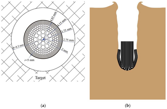
Figure 12.
(a) Cross-section diagram of the MD-WF/Zr-MG-I rod penetrating the target and (b) schematic diagram of failure process of the MD-WF/Zr-MG-I rod.
Table 2.
Bending space and ultimate bending diameter of WFs in MD-WF/Zr-MG-I.
The average diameter of the carters penetrated by MD-WF/Zr-MG-II rods is also about Ø 17 mm; Figure 13a shows the distance between WFs and center of the rod during the penetration process of the MD-WF/Zr-MG-I rod. According to Equation (2) and the test results, the bending space and ultimate bending diameter of WFs in MD-WF/Zr-MG-II is shown in Table 3. The bend spaces of Ø0.3 mm WFs and Ø0.5 mm WFs in the MD-WF/Zr-MG-II rod are larger than their ultimate bending diameter, but the bend spaces of Ø1.0 mm WFs are smaller than their ultimate bending diameter. Therefore, during the penetration process of the MD-WF/Zr-MG-II rod, Ø1.0 mm WFs shear failure occurs firstly, rather than bending deformation. Although the bend spaces of Ø0.3 mm WFs and Ø0.5 mm WFs are enough to bend, they will be cut by the Ø1.0 mm WFs and the crater wall because of the tiny distance between the broken Ø1 mm WFs and crater wall. Therefore, a conical head similar to depleted uranium alloys is formed during the penetration process of the MD-WF/Zr-MG-II rod, as shown in Figure 13b. The penetration failure mode of the MD-WF/Zr-MG-II rod is the shear failure layer by layer. The failed rod material is small and easy to flow out from the crater, so there is no residual rod in the crater, as shown in Figure 9.
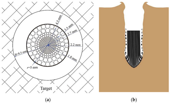
Figure 13.
(a) Cross-section diagram of the MD-WF/Zr-MG-II rod penetrating the target and (b) the schematic diagram of the failure process of the MD-WF/Zr-MG-II rod.
Table 3.
Bending space and ultimate bending diameter of WFs in MD-WF/Zr-MG-II.
Comparing with Figure 12 and Figure 13b, it can be found that the shape of the residual rod head is hemispherical when the penetration failure mode of the rod is bending and there is backflow of WFs, while the shape of the residual rod head is conical when the penetration failure mode of the rod is shear failure. According to the penetration mechanics, the penetration resistance of conical head is less than that of the hemispherical head despite the diameters of the two craters being same, so the penetration ability of the MD-WF/Zr-MG-II rods is higher than that of the MD-WF/Zr-MG-I rods, as shown in Figure 6. Moreover, if the aspect ratio of the rod increases, the residual WFs in the crater penetrated by the MD-WF/Zr-MG-I rod will hinder the outflow of the rod and target residues, which will have a negative influence on the penetration ability of the rod. Therefore, in the case of the large aspect ratio rod penetration, the MD-WF/Zr-MG-II rod will have greater advantage than the MD-WF/Zr-MG-I rod.
5. Discussion
The above analysis shows that the relationship of the bend space and ultimate bending diameter of WFs in the MD-WF/Zr-MG rod is an important factor affecting the penetration failure mode of the rod. If the bend spaces of all WFs in a rod are larger than their ultimate bending diameter, the penetration failure mode of the rod is the bending and backflow of WFs. In Figure 10, the test results show that the ultimate bending diameter of Ø0.5 mm WF is less than 0.6 mm, and the ultimate bending diameter of the Ø0.3 mm WF is less than 0.4 mm. According to Equation (2), even Ø0.5 mm WFs and Ø0.3 mm WFs are arranged in the outer layer of the rod, their bending spaces being larger than their ultimate bending diameter, which leads to the penetration failure of the bending and backflow of WFs. Previous experiments have shown that the penetration failure mode of the WF(0.3)/Zr-MG rod is the bending and backflow of WFs when the rod diameter is Ø5.6 mm, as shown in Figure 14.
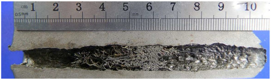
Figure 14.
Longitudinal section of crater penetrated by the Ø5.6 mm WF(0.3)/Zr-MG rod.
However, if the bend spaces of part of WFs in a MD-WF/Zr-MG rod are smaller than their ultimate bending diameter, shear failure of the rod will occur. Therefore, the relationship of the bend space and ultimate bending diameter of the WFs should be calculated by the design of MD-WF/Zr-MG.
It is assumed that the diameter of WFs of the MD-WF/Zr-MG rod is , the ultimate bending diameter of the outer layer WFs will be:
with as the function related to the properties of WF, it can be measured by bend tests.
It is assumed that the radius of MD-WF/Zr-MG rod is , the radius of crater penetrated by MD-WF/Zr-MG rod will be:
with as a function related to the properties of impact velocity, properties of rod materials, and target materials. Usually, the radius of the crater is proportional to the radius of the rod [37], then:
with as the parameter related to impact velocity, properties of rod materials, and target materials.
Compared with the bend space and the ultimate bending diameter of the WFs,
According to bending test results of WFs, the ultimate bending diameter of Ø1.0 mm WF is , the ultimate bending diameter of Ø0.5 mm WF is , and the ultimate bending diameter of Ø0.3 mm is WF . According to Equations (3) to (6) and the arrangement of WFs Figure 2, the value and volume fraction of WFs in the MD-WF/Zr-MG-I and MD-WF/Zr-MG-II rods during the penetration process is calculated and shown in Table 4. According to the calculation results in Table 4, only 8.05% of WFs in the MD-WF/Zr-MG-I rod do not have enough bending space during penetration, and fracture will occur. However, about 46.14% of WFs will break during MD-WF/Zr-MG-II rod penetration. Therefore, the penetration failure mode of the MD-WF/Zr-MG-I rod is bending and backflow of WFs, and the penetration failure mode of the MD-WF/Zr-MG-II rod is shear failure.
Table 4.
Value and the volume fraction of WFs in the MD-WF/Zr-MG-I rod and MD-WF/Zr-MG-II rod.
As the MD-WF/Zr-MG rod with shear failure mode exhibits stronger penetration capability than the MD-WF/Zr-MG rod with a failure mode of bending and backflow of WFs, when designing the MD-WF/Zr-MG, calculating the of WFs during penetration is necessary. The of as many WFs as possible should be less than 1.
6. Conclusions
In this paper, two kinds of MD-WF/Zr-MG are designed. Both the two MD-WF/Zr-MG contain Ø0.3 mm WFs, Ø0.5 mm WFs, and Ø1.0 mm WFs. In MD-WF/Zr-MG-I, the diameters of WFs increase gradually from inside to outside. In MD-WF/Zr-MG-II, the diameters of WFs decrease gradually from inside to outside. Penetration experiments of two MD-WF/Zr-MG rods are conducted respectively. According to the analysis of the residual rods and craters, the following conclusions are obtained.
- When multi-diameter WFs are added to WF/Zr-MG, the WF/Zr-MG rod retains the penetration self-sharpening feature and increases penetration stability. The WF/Zr-MG makes use of the advantages and avoids the disadvantages of WFs when WF/Zr-MG is reinforced by multiple diameter WFs. The penetration ability of MD-WF/Zr-MG-II rods is better than that of MD-WF/Zr-MG-I rods.
- The arrangement of WFs in MD-WF/Zr-MG has an important influence on its penetration failure mode. When the diameters of WFs increase gradually from inside to outside (MD-WF/Zr-MG-I), the penetration failure mode of MD-WF/Zr-MG rods into RHA is the bending and backflow of WFs. When the diameters of WFs decrease gradually from inside to outside (MD-WF/Zr-MG-II), the penetration failure mode of MD-WF/Zr-MG rods into RHA is the shear failure.
- The penetration failure mode of MD-WF/Zr-MG rods is related to the bend spaces and the ultimate bending diameters of WFs in it. If the bend spaces of all WFs are equal or larger than their ultimate bending diameters, the penetration failure mode of the MD-WF/Zr-MG-I rod is the bending and backflow of WFs, oppositely the penetration failure mode of the MD-WF/Zr-MG-II rod is the shear failure.
- When designing MD-WF/Zr-MG, the bending space and ultimate bending diameter of WFs should be calculated to ensure that the bending space of most parts of WFs is larger than their ultimate bending diameter.
Author Contributions
Conceptualization, C.D. and H.F.; methodology, Z.Z. and Z.D.; validation, K.W. and G.G.; formal analysis, G.G.; investigation, C.D., F.Z. and Z.D.; resources, H.F., Z.Z. and K.W.; data curation, L.X.; writing—original draft preparation, C.D.; writing—review and editing, G.G. and L.X.; visualization, F.Z.; supervision, G.G.; project administration, G.G. and Z.D.; funding acquisition, C.D. and G.G. All authors have read and agreed to the published version of the manuscript.
Funding
This research was funded by National Natural Science Foundation of China, grant number 12102201, 11802141, and 11772160 and the China Scholarship Council, grant number 201806840024.
Institutional Review Board Statement
Not applicable.
Informed Consent Statement
Not applicable.
Data Availability Statement
Not applicable.
Acknowledgments
We wish to express our gratitude to the members of our research team, Zhaojun Pang, Xi Chen, Shuai Yue, Jiangbo Wang, and Xiaodong Wang.
Conflicts of Interest
The authors declare no conflict of interest.
References
- Wang, W.H.; Dong, C.; Shek, C.H. Bulk metallic glasses. Mater. Sci. Eng. R Rep. 2004, 44, 45–89. [Google Scholar] [CrossRef]
- Schroers, J. Bulk Metallic Glasses. Phys. Today 2013, 66, 32–37. [Google Scholar] [CrossRef]
- Dandliker, R.B.; Conner, R.D.; Johnson, W.L. Melt infiltration casting of bulk metallic-glass matrix composites. J. Mater. Res. 1998, 13, 2896–2901. [Google Scholar] [CrossRef]
- Choi-Yim, H.; Conner, R.D.; Szuecs, F.; Johnson, W.L. Quasistatic and dynamic deformation of tungsten reinforced Zr57Nb5Al10Cu15.4Ni12.6 bulk metallic glass matrix composites. Scr. Mater. 2001, 45, 1039–1045. [Google Scholar] [CrossRef]
- Conner, R.D.; Dandliker, R.B.; Scruggs, V.; Johnson, W.L. Dynamic deformation behavior of tungsten-fiber/metallic glass matrix composites. Int. J. Impact Eng. 2000, 24, 435–444. [Google Scholar] [CrossRef]
- Zhang, H.F.; Li, H.; Wang, A.M.; Fu, H.M.; Ding, B.Z.; Hu, Z.Q. Synthesis and characteristics of 80 vol.% tungsten (W) fibre/Zr based metallic glass composite. Intermetallics 2009, 17, 1070–1077. [Google Scholar] [CrossRef]
- Qiu, K.Q.; Wang, A.M.; Zhang, H.F.; Ding, B.Z.; Hu, Z.Q. Mechanical properties of tungsten fiber reinforced ZrAlNiCuSi metallic glass matrix composite. Intermetallics 2002, 10, 1283–1288. [Google Scholar] [CrossRef]
- Zhang, B.; Fu, H.; Sha, P.; Zhu, Z.; Dong, C.; Zhang, H.; Hu, Z. Anisotropic compressive deformation behaviors of tungsten fiber reinforced Zr-based metallic glass composites. Mater. Sci. Eng. A 2013, 566, 16–21. [Google Scholar] [CrossRef]
- Zhang, B.; Fu, H.; Li, Z.; Zhu, Z.; Zhang, H.; Hu, Z. Anisotropic tensile properties of tungsten fiber reinforced Zr based metallic glass composites. Mater. Sci. Eng. A 2014, 619, 165–170. [Google Scholar] [CrossRef]
- Zhang, H.; Zhang, Z.F.; Wang, Z.G.; Zhang, H.F.; Zang, Q.S.; Qiu, K.Q. Effects of tungsten fiber on failure mode of zr-based bulk metallic glassy composite. Metall. Mater. Trans. A 2006, 37, 2459–2469. [Google Scholar] [CrossRef]
- Choi-Yim, H.; Schroers, J.; Johnson, W.L. Microstructures and mechanical properties of tungsten wire/particle reinforced Zr57Nb5Al10Cu15.4Ni12.6 metallic glass matrix composites. Appl. Phys. Lett. 2002, 80, 1906–1908. [Google Scholar] [CrossRef]
- Chen, J.H.; Chen, Y.; Jiang, M.Q.; Chen, X.W.; Zhang, H.F.; Dai, L.H. On the compressive failure of tungsten fiber reinforced Zr-based bulk metallic glass composite. Int. J. Solids Struct. 2015, 69, 428–441. [Google Scholar] [CrossRef]
- Ma, W.; Kou, H.; Chen, C.; LI, J.; Hu, R. Interfacial characteristics and dynamic mechanical properties of Wf/Zr-based metallic glass matrix composites. T. Nonferr. Met. Soc. 2008, 18, 77–81. [Google Scholar] [CrossRef]
- Ma, W.; Kou, H.; Chen, C.; Li, J.; Chang, H.; Zhou, L.; Fu, H. Compressive deformation behaviors of tungsten fiber reinforced Zr-based metallic glass composites. Mater. Sci. Eng. A 2008, 486, 308–312. [Google Scholar] [CrossRef]
- Chen, G.; Hao, Y.; Chen, X.; Hao, H. Compressive behaviour of tungsten fibre reinforced Zr-based metallic glass at different strain rates and temperatures. Int. J. Impact Eng. 2017, 106, 110–119. [Google Scholar] [CrossRef]
- Zhu, F.L.; Chen, Y.; Zhu, G.L. Numerical simulation study on penetration performance of depleted Uranium (DU) alloy fragments. Def. Technol. 2021, 17, 50–55. [Google Scholar] [CrossRef]
- Du, C.; Shu, D.; Du, Z.; Gao, G.; Wang, M.; Zhu, Z.; Gao, G.; Wang, M.; Zhu, Z.; Xu, L. Effect of L/D on penetration performance of tungsten fibre/Zr-based bulk metallic glass matrix composite rod. Int. J. Refract. Met. Hard Mater. 2019, 85, 105042. [Google Scholar] [CrossRef]
- Chen, X.W.; Chen, G. Experimental research on the penetration of tungsten-fiber/metallic-glass matrix composite material bullet into steel target. EPJ Web Conf. 2012, 26, 1049. [Google Scholar] [CrossRef]
- Chen, X.W.; Wei, L.M.; Li, J.C. Experimental research on the long rod penetration of tungsten-fiber/Zr-based metallic glass matrix composite into Q235 steel target. Int. J. Impact Eng. 2015, 79, 102–116. [Google Scholar] [CrossRef]
- Rong, G.; Huang, D.W.; Yang, M.C. Penetrating behaviors of Zr-based metallic glass composite rods reinforced by tungsten fibers. Theor. Appl. Fract Mec. 2012, 58, 21–27. [Google Scholar] [CrossRef]
- Guo, W.; Jiang, H.; Wang, S.; Wan, M.; Fang, X.; Tian, S. Self-sharpening ability enhanced by torque gradient in twisted tungsten-fiber-reinforced Cu-Zn matrix composite. J. Alloys Compd. 2019, 794, 396–401. [Google Scholar] [CrossRef]
- Lee, K.; Lee, S.; Lee, S.; Lee, S. Compressive and Tensile Properties of Tungsten-Continuous-Fiber-Reinforced Zr-Based Amorphous Alloy Matrix Composite Fabricated by Liquid Pressing Process. Metall. Mater. Trans. A 2008, 39, 1319–1326. [Google Scholar] [CrossRef]
- Lee, S.; Lee, S.; Lee, S.; Kim, N.J. Microstructure and Mechanical Properties of Two Continuous-Fiber-Reinforced Zr-Based Amorphous Alloy Composites Fabricated by Liquid Pressing Process. Metall. Mater. Trans. A 2008, 39, 763–771. [Google Scholar] [CrossRef][Green Version]
- Li, J.C.; Chen, X.W.; Huang, F.L. FEM analysis on the deformation and failure of fiber reinforced metallic glass matrix composite. Mater. Sci. Eng. A 2016, 652, 145–166. [Google Scholar] [CrossRef]
- Li, J.C.; Chen, X.W.; Huang, F.L. FEM analysis on the ‘’self-sharpening’’ behavior of tungsten fiber/metallic glass matrix composite long rod. Int. J. Impact Eng. 2015, 86, 67–83. [Google Scholar] [CrossRef]
- Xue, Y.; Zhong, X.; Wang, L.; Fan, Q.; Zhu, L.; Fan, B.; Zhang, H.; Fu, H. Effect of W volume fraction on dynamic mechanical behaviors of W fiber/Zr-based bulk metallic glass composites. Mater. Sci. Eng. A 2015, 639, 417–424. [Google Scholar] [CrossRef]
- Chen, S.; Zhang, L.; Fu, H.M.; Li, Z.K.; Zhu, Z.W.; Li, H.; Zhang, H.W.; Wang, A.M.; Wang, Y.D.; Zhang, H.F. Compressive mechanical properties and failure modes of Zr-based bulk metallic glass composites containing tungsten springs. Mater. Des. 2018, 160, 652–660. [Google Scholar] [CrossRef]
- Chen, S.; Li, W.Q.; Zhang, L.; Fu, H.M.; Li, Z.K.; Zhu, Z.W.; Li, H.; Zhang, H.W.; Wang, A.M.; Wang, Y.D.; et al. Dynamic compressive mechanical properties of the spiral tungsten wire reinforced Zr-based bulk metallic glass composites. Compos. Part B Eng. 2020, 199, 108219. [Google Scholar] [CrossRef]
- Zhang, Z.; Kong, J.; Liu, X.; Song, X.; Dong, K. Preparation, microstructure and mechanical properties of tungsten fiber reinforced LaAlCuNi metallic glass matrix composites. Intermetallics 2021, 132, 107139. [Google Scholar] [CrossRef]
- Zhang, B.; Fu, H.M.; Zhu, Z.W.; Zhang, H.F.; Dong, C.; Hu, Z.Q. Effect of W fiber diameter on the compressive mechanical properties of the Zr-based metallic glass composites. Acta Metall. Sin. 2013, 49, 1191–1200. [Google Scholar] [CrossRef]
- Du, C.X.; Du, Z.H.; Zhu, Z.W. Effect of impact velocity and diameter of tungsten fiber on penetration ability of Wf/Zr-based metallic glass composite penetrator. Rare Met. Mater. Eng. 2017, 46, 1632–1637. [Google Scholar]
- Magness, L.S. High strain rate deformation behaviors of kinetic energy penetrator materials during ballistic impact. Mech. Mater. 1994, 17, 147–154. [Google Scholar] [CrossRef]
- Terentyev, D.; Van Renterghem, W.; Tanure, L.; Dubinko, A.; Riesch, J.; Lebediev, S.; Khvan, T.; Verbeken, K.; Coenen, J.W.; Zhurkin, E.E. Correlation of microstructural and mechanical properties of K-doped tungsten fibers used as reinforcement of tungsten matrix for high temperature applications. Int. J. Refract. Met. Hard Mater. 2019, 79, 204–216. [Google Scholar] [CrossRef]
- Terentyev, D.; Riesch, J.; Lebediev, S.; Bakaeva, A.; Coenen, J.W. Mechanical properties of as-fabricated and 2300 °C annealed tungsten wire tested up to 600 °C. Int. J. Refract. Met. Hard Mater. 2017, 66, 127–134. [Google Scholar] [CrossRef]
- Terentyev, D.; Riesch, J.; Lebediev, S.; Khvan, T.; Dubinko, A.; Bakaeva, A. Strength and deformation mechanism of tungsten wires exposed to high temperature annealing: Impact of potassium doping. Int. J. Refract. Met. Hard Mater. 2018, 76, 226–233. [Google Scholar] [CrossRef]
- Wilbeck, J.S.; Charles, E.; Anderson, J.; John, P.; Riegel, I.; Lankford, J.; Mullin, S.A.; Bodner, S.R. A Short Course on Penetration Mechanics; Southwest Research Institute: San Antonio, TX, USA, 1986. [Google Scholar]
- Rosenberg, Z.; Kositski, R. The hole diameter in metallic plates impacted by hypervelocity projectiles. Int. J. Impact Eng. 2017, 102, 147–155. [Google Scholar] [CrossRef]
Publisher’s Note: MDPI stays neutral with regard to jurisdictional claims in published maps and institutional affiliations. |
© 2022 by the authors. Licensee MDPI, Basel, Switzerland. This article is an open access article distributed under the terms and conditions of the Creative Commons Attribution (CC BY) license (https://creativecommons.org/licenses/by/4.0/).