Article

Petawatt Femtosecond Laser Pulses from Titanium-Doped Sapphire Crystal

by
Hiromitsu Kiriyama
1,*,
Alexander S. Pirozhkov
1,
Mamiko Nishiuchi
1,
Yuji Fukuda
1,
Akito Sagisaka
1,
Akira Kon
1,
Yasuhiro Miyasaka
1,
Koichi Ogura
1,
Nicholas P. Dover
1,
Kotaro Kondo
1,
Hironao Sakaki
1,
James K. Koga
1,
Timur Zh. Esirkepov
1,
Kai Huang
1,
Nobuhiko Nakanii
1,
Masaki Kando
1,
Kiminori Kondo
1,
Stefan Bock
2,
Tim Ziegler
2,
Thomas Püschel
2,
Karl Zeil
2 and
Ulrich Schramm
2
add Show full author list remove Hide full author list
1
Kansai Photon Science Institute, National Institutes for Quantum and Radiological Science and Technology, 8-1-7 Umemidai, Kizugawa, Kyoto 619-0215, Japan
2
Helmholtz-Zentrum Dresden-Rossendorf, Bautzner Landstra.e 400, 01328 Dresden, Germany
*
Author to whom correspondence should be addressed.
Crystals 2020, 10(9), 783; https://doi.org/10.3390/cryst10090783
Submission received: 31 July 2020 / Revised: 31 August 2020 / Accepted: 1 September 2020 / Published: 3 September 2020
(This article belongs to the Special Issue Development of High Intensity Crystal Laser and Its Applications)

Abstract

:
Ultra-high intensity femtosecond lasers have now become excellent scientific tools for the study of extreme material states in small-scale laboratory settings. The invention of chirped-pulse amplification (CPA) combined with titanium-doped sapphire (Ti:sapphire) crystals have enabled realization of such lasers. The pursuit of ultra-high intensity science and applications is driving worldwide development of new capabilities. A petawatt (PW = 1015 W), femtosecond (fs = 10−15 s), repetitive (0.1 Hz), high beam quality J-KAREN-P (Japan Kansai Advanced Relativistic ENgineering Petawatt) Ti:sapphire CPA laser has been recently constructed and used for accelerating charged particles (ions and electrons) and generating coherent and incoherent ultra-short-pulse, high-energy photon (X-ray) radiation. Ultra-high intensities of 1022 W/cm2 with high temporal contrast of 10−12 and a minimal number of pre-pulses on target has been demonstrated with the J-KAREN-P laser. Here, worldwide ultra-high intensity laser development is summarized, the output performance and spatiotemporal quality improvement of the J-KAREN-P laser are described, and some experimental results are briefly introduced.

1. Introduction

Since the first demonstration of the high-power, ultra-fast laser [1], vigorous research attempts have been made to increase the laser peak power and focused intensity in order to reach extreme conditions within the laboratory. Initial jumps of several orders of magnitude in peak power came with the invention of Q (Quality)-switching for generating nanosecond pulse durations [2] followed by mode locking for producing shorter, picosecond durations [3,4]. The development of a high peak power laser system historically depends on the short-pulse generation from the laser oscillator and its subsequent amplification. However, the direct amplification of these pulses suffered from nonlinear effects, leading to degradation of the beam quality and even to optical damage in the laser system. In the mid-1980s, the invention of chirped-pulse amplification (CPA) was presented as an appropriate technique for a significant increase in the peak power of high energy femtosecond pulsed lasers [5].
Laser systems based on the CPA technique employ the concept of stretching and compressing an ultra-short laser pulse in the temporal domain before and after the amplification, respectively. This technique minimized the damage risk related to nonlinear effects. An additional transformative invention was the transition-metal-doped gain medium, titanium-doped sapphire (Ti:Al2O3, Ti:sapphire) in 1986 [6]. The Ti:sapphire crystal has a very large gain bandwidth of ~640 to ~1100 nm, enabling ultra-short femtosecond pulses. The Kerr lens mode-locking (KLM) technique stabilized femtosecond laser pulses from the Ti:sapphire laser oscillators and made the CPA technique suitable for constructing petawatt (PW)-class laser systems in a small-scale laboratory [7,8,9,10,11,12]. Thus, Ti:sapphire CPA lasers have become standard tabletop sources of repetitive powerful femtosecond laser pulses. In addition, according to the successful demonstration and operation of PW-class laser systems, programs with the aim of multi-PW and even 10 PW laser systems have been developed, planned, and proposed at a number of laboratories and facilities around the world [13].
Recent achievements of Ti:sapphire CPA lasers include the generation of pulses at peak powers up to 4.2 PW at a repetition rate of 0.1 Hz [14], 3 PW at 1 Hz [15], and single-shot broadband pulse energies up to 339 J to potentially achieve 10 PW [16]. Two 10 PW lasers capable of one shot every minute have been constructed in Romania under the European Extreme Light Infrastructure (ELI) program [17]. The generation of 0.85 PW pulses of 30 fs pulse duration at 3.3 Hz with a record average power of 85 W [18] has been demonstrated with a Ti:sapphire laser using flash-lamp pumped Nd:glass pump lasers. A Ti:sapphire laser named HAPLS (the high-repetition-rate advanced petawatt laser system) with laser diode-pumped Nd:glass laser pump lasers has been designed and constructed toward generating petawatt pulses at 10-Hz repetition rate [19].
An alternative approach for potentially generating petawatt peak powers and beyond, the optical parametric chirped-pulse amplification (OPCPA) technique [20,21] is also being developed. A 4.9-PW peak power has been demonstrated at single-shot operation using the OPCPA technique [22]. Based on the demonstration of a multi-PW laser system, a 100 PW laser in China, named the Station of Extreme Light (SEL), has been proposed and will be developed in 2024 [23]. The OPCPA technique has great advantages, such as higher peak power, higher temporal contrast, and so on, over Ti:sapphire laser technology. However, this technique exhibits difficulties related to the pump laser development and a lower efficiency.
Highly focused intensities of over 1021 W/cm2 [24,25,26] have been made available by using extremely high laser peak powers of PW to multi-PW. Higher focused intensities of 1023 W/cm2 will be achievable with 100-PW-class lasers in the near future. Experimental demonstrations of new phenomena and behavior and the understanding of physical mechanisms in ultra-high electromagnetic fields with ultra-high intensities up to over 1022 W/cm2 are highly anticipated. However, to date, experimental investigations have been demonstrated with focused intensities ranging from 1018 to 1021 W/cm2, up to a maximum of a few 1021 W/cm2.
Any pulses with intensities of 1010 to 1011 W/cm2 or more before the main pulse can create unwanted preformed plasma on solid targets and have a large impact on the resulting high-intensity, laser–plasma interaction. Therefore, for most plasma physics’ research, increased focused intensities require a commensurate improvement in temporal contrast between the main and pre-pulses. Here, the temporal contrast is defined as the ratio of the intensity of the pre-pulse to the main pulse. Since many laboratories and facilities can deliver highly focused intensities, the temporal contrast has become a major issue, and is today under serious investigation throughout the world. There exist three kinds of pulses before the main pulse in CPA lasers: Amplified spontaneous emission (ASE) extending over nanoseconds [27], discrete pulses before the main pulse called pre-pulses [28], and an exponentially rising slope, typically tens of picoseconds around the main pulse called the pedestal. The ASE and the pre-pulses may greatly affect the target even a few hundred picoseconds to nanoseconds prior to the main pulse. The last one, the pedestal, can extend the leading edge of the main pulse by several picoseconds at an intensity that is likely to be well above the plasma generation threshold and is coming from both the nonlinear transfer of characteristic post-pedestal to pre-pedestal [29] and the optics’ surface roughness in the stretcher and compressor [30]. The pedestal is difficult to remove in the laser itself, without using plasma mirrors [31] or second harmonic generation [18]
Various temporal contrast improvements have been proposed and investigated. These include using double CPA (DPCA) [32], cross-polarized wave generation (XPW) [33], saturable absorbers [9], and optical parametric amplification (OPA) [34]. Because the ASE is suppressed to 10−11–10−12 even at PW peak powers with these techniques, the pre-pulses, which have previously been buried and invisible, have become apparent.
It is essential to remove the post-pulses to eliminate the pre-pulses. The post-pulses do not directly affect the laser-plasma interaction process and can be ignored. However, in a CPA system, the duration of the stretched pulse is longer compared with the time difference between the main and post-pulses, and these pulses overlap in time and interfere with each other. The frequency chirp and the delay between these pulses lead to spectral interference. This sinusoidal spectral modulation can change the optical properties of the optical elements in the laser chain. The time-dependent optical properties can then modulate the spectral phase due to the intensity dependence of the B-integral (defined as the measure of the nonlinear phase shift of light) accumulated in the optical elements. The compressor converts this modulation by the post-pulse to a new pre-pulse [28,35,36,37,38]. These pre-pulses with relatively high intensities must be eliminated in order to avoid unwanted plasma formation or significant modification of the experimental target conditions before the arrival of the main pulse. Thus, it is important to investigate and remove the pre-pulses generated by post pulses, along with the accumulated B-integral values in the laser chain.
In this paper, we describe our high-intensity laser facility. The previous facility, named J-KAREN (Japan Kansai Advanced Relativistic ENgineering), delivered 1021 W/cm2 intensity on target at single shot [39]. The upgraded laser facility, named J-KAREN-P, can realize petawatt peak powers at a repetition rate of 0.1 Hz with an intensity capability of over 1022 W/cm2 on target [40,41]. We also report the investigation of the behavior of the pre-pulses by post-pulses at the J-KAREN-P laser facility. Based on our experience and understanding of pre-pulse removal, we have achieved a high temporal contrast of 10−12 and removed most of the pre-pulses. This is the first demonstration of the high accurately estimated intensity of 1022 W/cm2 on target and high temporal contrast of 10−12 with pre-pulse removal, to the best of our knowledge. The excellent temporal and spatial performance and overall high quality of the laser system will enable many high-field applications. We also briefly introduce recent experimental results of the applications with the J-KAREN-P laser system in the relativistic regime of laser–matter interactions such as laser acceleration of ions and electrons, coherent and incoherent XUV (eXtreme UltraViolet) and X-ray generation, and prospects for high-field science experiments.

2. Petawatt Femtosecond J-KAREN-P Laser System

2.1. Overall System

The J-KAREN-P laser system is the flagship laser system at the Kansai Photon Science Institute (KPSI) of the National Institutes for Quantum and Radiological Science and Technology (QST). The system features a number of innovations, which make it unique. The overall schematic diagram for the J-KAREN-P laser system is shown in Figure 1. The main features of the laser system are: (1) A robust high-contrast front end featuring a saturable absorber and OPCPA operation with low gain [9], (2) high-energy amplification by four Ti:sapphire amplifiers with optimum and moderate amplification gain, (3) simple off-axis beam expanders based on reflective-type concave and convex mirrors with low aberrations, (4) active compensation of the residual spectral-phase distortion with two high-dynamic-range acousto-optic programmable dispersive filters (AOPDFs) and active correction of the wavefront with an adaptive optic (deformable mirror), and (5) compressor consisting of four gold-coated holographic high-quality large gratings. The laser is guided to two different target chambers for short focal length (f-number from 1/1.3 to 1/3) and long focal length (f-number from 1/3 to 1/10) configurations, providing flexibility for ultra-high intense laser–plasma interaction experiments.

2.2. Front-End-First, CPA System

A commercial Ti:sapphire laser (Spectra-Physics, Femtopower Compact Pro) with the saturable absorber is used as a first CPA-stage, high-contrast, front-end system to provide seed pulses for the second CPA stage. The stable ultra-short laser oscillator at 80-MHz repetition rate is designed with dispersion compensation in order to generate sub-10 fs laser pulses. The laser pulses from the oscillator are amplified in a multi-pass Ti:sapphire amplifier up to ~1 mJ and recompressed well to a pulse duration of ~25 fs with the AOPDF and grating compressor. The pulses are transmitted through a colored glass filter as a saturable absorber with ~25% efficiency to suppress the ASE, the pre-pulses, and the pedestal on femtosecond timescales initially. In the second CPA stage, the cleaned pulses with higher energy are temporally stretched (chirped) to over ns duration by passing through an aberration-free, all-reflective, Offner-type stretcher [42]. This stretcher consists of a 1480-grooves/mm grating, a 2000-mm radius of curvature mirror (400-mm width, 80-mm height), a 1000-mm radius of curvature convex mirror (150-mm width, 10-mm height), and a roof mirror. The stretched pulses are passed through another AOPDF to pre-compensate the spectral-phase change due to the propagation. The pulses before the OPCPA pre-amplifier have ~20 μJ energies due to the energy loss in the saturable absorber, stretcher, AOPDF, and steering mirrors.

2.3. OPCPA Pre-Amplifier

The ASE, pre-pulses, and pedestal are generated mostly in the pre-amplifier stage, and then amplified along with the main pulse in power amplifier stages. In addition, spectral narrowing by gain-narrowing and gain-depletion effects occurs during the amplification process, mainly in the pre-amplifier. Thus, the OPCPA pre-amplifier was adopted because of low noise amplification [43] and the support of broad spectral bandwidth [44].
Figure 2 shows the detailed layout of our OPCPA pre-amplifier. The OPCPA pre-amplifier consists of three Type I ß-barium borate (BBO) crystals. The size of the first two crystals is 7 mm × 7 mm × 19.5 mm and that of the third crystal is 7 mm × 7 mm × 16 mm. For broad spectral bandwidth, the external angle between the seed and pump lasers and phase-matching angle is set through the simulation to be 3.9° and 23.8°, respectively. All of the crystals in our OPCPA pre-amplifier are pumped by the same pump pulse to reduce the complexity and size of the system, as shown in Figure 2.
The spectral narrowing should be suppressed to obtain broad spectral bandwidth for achieving a short pulse after recompression. The spectral gain profile of the OPCPA depends on the temporal intensity profile of the pump laser. Thus, a custom-built, frequency-doubled, neodymium-doped yttrium aluminum garnet (Nd:YAG) laser at 10 Hz (Amplitude Laser Group Continuum, Intrepid) is used as a pump laser for our OPCPA pre-amplifier. In this pump laser, the output beam from a continuous wave (CW), single-longitudinal-mode laser diode (LD)-pumped, Yb-doped fiber laser is arbitrarily shaped with the programmable optical pulse shaper and amplified in a rod pre-amplifier, a regenerative amplifier, and two rod main amplifiers, and then frequency doubled in a lithium triborate (LBO) crystal. The programmable optical pulse shaper consists of a Mach-Zehnder modulator, bias control circuit, and a pulse synthesizer. The programmable time step is 125 ps with rise and fall time of 150 ps and the pulse duration can be changed from 1 ns to 4 ns at the few hundred mJ level. The pump laser is synchronized well with the seed laser within ±100 ps. The near-field beam profile has a near homogeneous, flat-topped, spatial-intensity distribution. The beam image of the pump laser is first relayed to the center, located between the first two crystals, by means of a vacuum image telescope, which simultaneously adjusts the pump beam diameter to maintain uniform intensity. The second image plane is located in the center of the third crystal. The pump and seed beam diameters are matched to be ~4 mm.
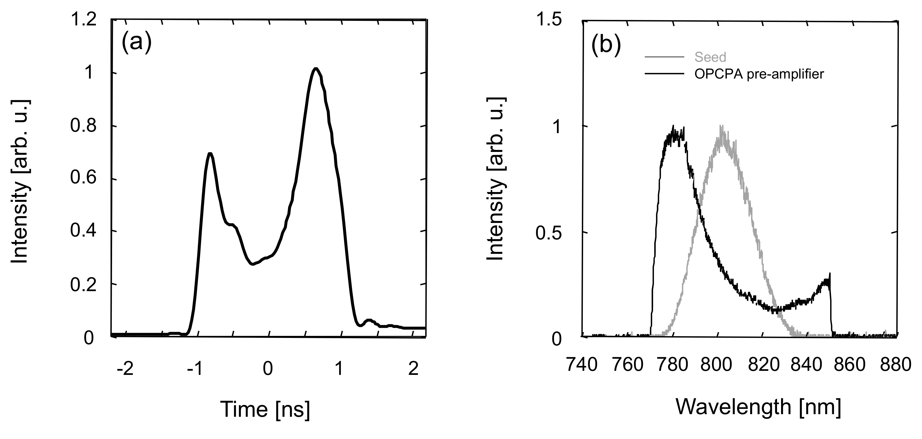
Therefore, the output spectrum from the OPCPA pre-amplifier can be shaped by controlling the temporal profile of the pump laser. A beautiful example of this pump laser’s capability is the ability to shape the OPCPA spectrum to compensate for gain narrowing. Figure 3a displays the representative measured pulse shape of the pump laser for the OPCPA pre-amplifier for broadband amplification and representative measure of the seed spectrum (gray line), as shown in Figure 3b. Figure 3b also shows output spectra of the OPCPA pre-amplifier for the broadband amplification pumped by a temporally shaped laser (black line), respectively. The temporal profile is controlled to reduce the intensities of longer wavelength components for broadband amplification because the longer wavelength components are enhanced due to saturation in the subsequent Ti:sapphire amplifiers. The spectral bandwidth from the stretcher is measured to be ~30 nm (full width at half maximum, FWHM). With OPCPA amplification, the shaped and broadened amplified spectrum is obtained with ~80-nm bandwidth (tail-to-tail width), which is limited by the stretcher design.
Parametric fluorescence can greatly deteriorate temporal contrast under conditions of high-gain and gain-saturation operation, for example, when using the low seed energy of nanojoule in combination with high pump intensities. Therefore, we improve the temporal contrast by operating the OPCPA in a higher seed energy of ~20 μJ, low-gain mode, well below the gain saturation regime [9]. Figure 4 shows the measured output energy of the OPCPA pre-amplifier for broadband amplification as a function of the energy of the pump laser. We operate the OPCPA at a low gain of only ~150 to minimize the parametric fluorescence and, thereby, enhance the contrast. With an incident pump energy of ~50 mJ, an energy of ~3 mJ of the amplified pulses at the output of the OPCPA is sufficient seeding energy for the subsequent Ti:sapphire amplifiers. The output pulses from the OPCPA are passed through an ultra-fast Pockels cell to eliminate the several hundred picoseconds to nanosecond order ASE for further temporal contrast enhancement.

2.4. Ti:sapphire Pre-Amplifier and Power Amplifier

The broadband pulses from the OPCPA are sent into a Ti:sapphire pre-amplifier. This amplifier is based on four-pass geometry and uses a Ti:sapphire crystal with a diameter of 20 mm. The pump laser for this amplifier is a frequency-doubled, Q-switched Nd:YAG laser, operating at a repetition rate of 10 Hz with a maximum pulse energy up to ~0.8 J (Amplitude Laser Group Continuum, Powerlite 9010). The beam from the pump laser is divided into two beams, which are all relayed to opposite faces of the Ti:sapphire crystal, resulting in uniform population inversion across the beam. A maximum output energy of ~250 mJ is obtained for the highest gain configuration. Because a small thermal-lensing effect occurs in this amplifier, the incident beam is slightly diverged by precisely adjusting the distance between the reflective-type concave and convex mirrors in the off-axis beam expander before the Ti:sapphire pre-amplifier to compensate. The collimated ~6-mm-diameter beam is obtained with four-pass amplification.
The output of the Ti:sapphire pre-amplifier is up collimated to ~18-mm diameter with the off-axis beam expander after the Ti:sapphire pre-amplifier and then sent into the Ti:sapphire power amplifier. This amplifier is also based on four-pass geometry and cryogenically cooled to cancel the thermal distortion in the crystal. A maximum total pump energy of up to ~6 J (532 nm) from six commercially available, frequency-doubled, Q-switched Nd:YAG lasers (Spectra-Physics, Quanta-Ray Pro-350) operating at a repetition rate of 10 Hz could be irradiated onto the 40-mm-diameter Ti:sapphire crystal. Image relay telescopes for all six pump lasers are used to transfer the spatially uniform beam profile at the image point to the Ti:sapphire crystal and to avoid optical damage caused by diffractive effects. Owing to the high average pump power of ~60 W, the crystal needs to be cooled down efficiently to reduce beam distortion and thermal-lensing effects. Therefore, it is enclosed in a vacuum chamber with antireflection-coated windows and cooled with a temperature stabilized cryostat. At temperatures in the 100 K range, the thermal conductivity of Ti:sapphire is increased by a factor of ~30, and the refractive index temperature gradients are decreased by a factor of ~7 with respect to room temperature. At 100 K, the thermal-focusing length of the amplifier is approximately 4000 m under maximum pumping conditions. The thermal-lensing effect is, therefore, adequately compensated with the cryogenically cooled crystal. With ~6 J of maximum pump energy incident on the crystal, this amplifier outputs a pulse with over 3 J, with a conversion efficiency of ~50%. We routinely operate the pre-amplifier and power amplifier at low gains to enhance the contrast and amplify the pulses to energies of ~45 mJ and ~2 J in the pre-amplifier and power amplifier, respectively.

2.5. Ti:sapphire Booster Amplifiers 1 and 2

The laser pulses are expanded from ~18 mm to ~50 mm in diameter by an off-axis beam expander with aberration compensation [45] before entering the Ti:sapphire booster amplifier 1 (BA1) operating at 0.1 Hz for higher energy amplification. The amplifier is based on three-pass geometry and uses an 80-mm-diameter Ti:sapphire crystal. The BA1 is pumped with two frequency-doubled, Q-switched Nd:glass lasers (Amplitude Laser Group Continuum, Constellation II-C, San Jose, CA, USA). Each Nd:glass laser produces ~25 J with 2 beams at 527 nm in ~15-ns (FWHM) pulse duration at 0.1-Hz repetition rate and has almost a flat-top, near-field profile. The beam image of the Nd:glass laser is relayed to the Ti:sapphire crystal by means of a vacuum image telescope, which simultaneously adjusts the Nd:glass laser beam diameter from ~22 mm to ~50 mm diameters, to maintain a uniform profile. In order to suppress parasitic lasing that is associated with Fresnel reflection from the cylinder inner surface, we have employed refractive index-matched liquid with broadband-absorbing dye. With BA1, the broadband laser energy is amplified to ~23 J, giving a conversion efficiency of ~49%.
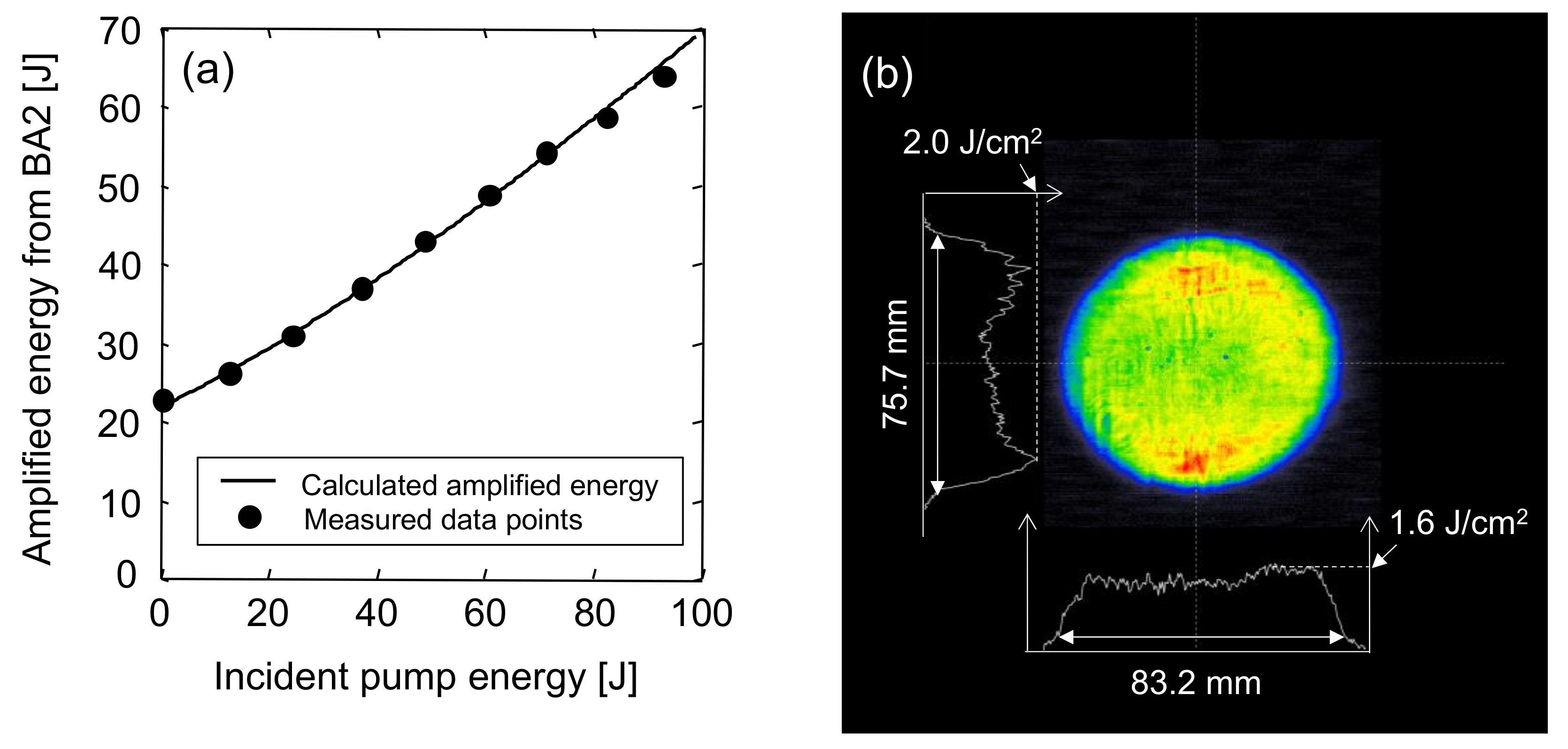
The pulses are also expanded to ~80 mm in diameter by the off-axis beam expander with aberration compensation for further amplification in the Ti:sapphire booster amplifier 2 (BA2) at 0.1 Hz. The amplifier is based on two-pass geometry and uses a commercially available disk, 120 mm in diameter. The BA2 is pumped with four frequency-doubled, Q-switched Nd:glass lasers (three are produced by Amplitude Laser Group Continuum, Constellation II-C, one is by Thales, ATLAS 25), delivering a total energy of ~100 J at 527 nm. The Nd:glass laser from Thales produces ~25 J with 2 beams at 527 nm in ~10-ns (FWHM) pulse duration at 0.1-Hz repetition rate and has an almost flat-top, near-field profile. The Nd:glass lasers are all image relayed to transfer the spatially uniform beam profile to the Ti:sapphire crystal. The maximum energy from BA2 is ~63 J with an incident pump energy of ~92 J, as shown in Figure 5a. The parasitic lasing is also suppressed by using index-matched, absorbing, cladding liquid. No energy saturation is observed within the investigated energy range. As can be seen from Figure 5a, there is good agreement between the experimental results and a theoretical prediction based on a Frantz-Nodvik simulation [46]. The standard deviation for 36 shots from the final amplifier is 0.2 J. A homogeneous, flat-top, spatial profile is attained, as shown in Figure 5b.
Figure 6 displays representative measured spectra for the broadband amplification of the seed (gray line), output of the OPCPA pre-amplifier pumped by a temporally shaped laser (black line), the Ti:sapphire pre-amplifier (orange line), the power amplifier (green line), the booster amplifier 1 (blue line), and the booster amplifier 2 (red line). The longer wavelength components are enhanced with amplification in the Ti:sapphire amplifiers. With the optimization of the OPCPA output spectrum by using precise control of the temporal profile of the pump pulse, the final amplified laser pulse can be broadened to ~80 nm (FWHM), which can support a pulse duration below ~30 fs. Consequently, this temporal profile shaping of the pump pulse facilitates optimization of the OPCPA-output-spectrum profile for near-perfect compensation of the gain-depletion effect.

2.6. Recompressed Pulse Duration and Focusability

A smaller compressor is placed beside the final amplifier for pulse duration measurements. The spectral phase information is obtained with a high-dynamic-range, single-shot, spectral-phase measurement system (Wizzler, FASTLITE) after the compressor, and then sent back to the AOPDF to minimize the phase distortion [47]. After the phase correction applied by the AOPDF and the Wizzler feedback loop, the minimum pulse duration of the recompressed laser pulse is 28 fs, which is a near Fourier-transform-limited pulse, as shown in Figure 7a. Figure 7b demonstrates the system can produce highly stable pulses with a standard deviation of 1.0 fs over 500 consecutive shots. The total transmission efficiency from the laser room to the target chamber including the compressor is ~60%, resulting in an expected peak power of over a PW at 0.1 Hz on target.
A deformable mirror (Imagine Optics, ILAO STAR B95-52, Orsay, France) with a wavefront sensor based on the Shack Hartmann technique (Imagine Optics, HASO3-32) is installed for the ~90-mm-diameter beam between the final amplifier and compressor to correct the wavefront distortion. The deformable mirror, which has a clear aperture of 95 mm, uses 52 mechanical actuators with astatic floating heads that controllably deform the membrane with nanometric precision. Figure 8 shows representative J-KAREN-P laser wavefronts and corresponding calculated and measured spots. Figure 8a–d shows the wavefront before the deformable mirror for a ~90-mm-diameter beam, the wavefront before the compressor for a ~280-mm-diameter beam after aberration correction, the calculated spot (point spread function (PSF)) corresponding to Figure 8a, and the measured at-focus spot (300 terawatt = TW = 1012 W) 280-mm-diameter beam after the compressor attenuated with 10 wedges and focused with an f/1.3 off-axis parabolic mirror (OAP) in vacuum), respectively. In Figure 8c,d, the maxima correspond to the corresponding Strehl ratios. As can be seen from Figure 8b, a residual wavefront aberration of 0.07 μm (root mean square (rms)) is obtained after correction. The amplified laser pulses are expanded to ~280 mm in diameter by the off-axis beam expander with aberration compensation [42] and are compressed in a vacuum compressor composed of four 1480-grooves/mm, gold-coated holographic gratings with a size of 565 × 360 mm2. The Strehl ratio calculated as [24] the ratio of effective area of the diffraction-limited spot (i.e., the Fourier-transformed measured near field) and measured focal spot, Figure 8d, is 0.54, which means that the focal spot is close to the diffraction-limited one. The size of the focal spot formed by an f/1.3 focusing optic is measured to be 1.32 μm (FWHM) and 1.37 μm (FWHM) in the horizontal and vertical directions, respectively. According to our precise measurement of the focal spot and energy contained within it, a peak intensity of 1022 W/cm2 on target is achieved at the 0.3 PW power level [24].

3. Investigation of Temporal Contrast in the J-KAREN-P Laser System

3.1. Real Pre-Pulses’ Generation by Post-Pulses

We experimentally investigated the creation of the real pre-pulses from post-pulses generated by internal reflections in the optical components in the laser chain, through nonlinear processes associated with B-integral [28,35,36,37,38]. The experiments were performed with the petawatt laser facility J-KAREN-P. The laser pulses were stretched to ~0.5 ns and compressed down to ~40 fs in this experiment. To generate the post-pulses, ~1- and ~11.8-mm thickness, uncoated, plane-parallel plates made of fused silica were inserted into the laser beam perpendicular to its axis and placed before the Ti:sapphire pre-amplifier. The typical reflectivity is ~3.4% per surface of the plane-parallel plates to generate post-pulses by internal reflections. Because the stretched pulse duration was longer than the time difference between the main and post-pulses, the post-pulse generated by a ~1-mm, plane-parallel plate and main pulse overlapped in time considerably, while in contrast the post-pulse generated by a ~11.8-mm plate and main pulse only partially overlapped. The temporal contrast was measured with a third-order cross-correlator (Amplitude Technology, Sequoia, Paris, France). These plane-parallel plates lead to post-pulses with a contrast level due to Fresnel reflection of ~10−3 at time t, determined by t = 2 dn/c where d and n are the thickness and refractive index n of the plane-parallel plate, and c is the speed of light. The d = ~1 and = 11.8 mm lead to t = ~10 and ~118 ps for n = ~1.45. For the confirmation of calibration, the artificial pre-pulses were measured under conditions without the nonlinear coupling effect by placing the plane-parallel plates just before the third-order cross-correlator (after the compressor). The artificial pre-pulses appeared, owing to the mixing of the fundamental of the main pulse and second harmonic of the post-pulse in the third-order cross-correlation process. The temporal contrast of these artificial pre-pulses was equal to ~10−6, the square of the post-pulse contrast.
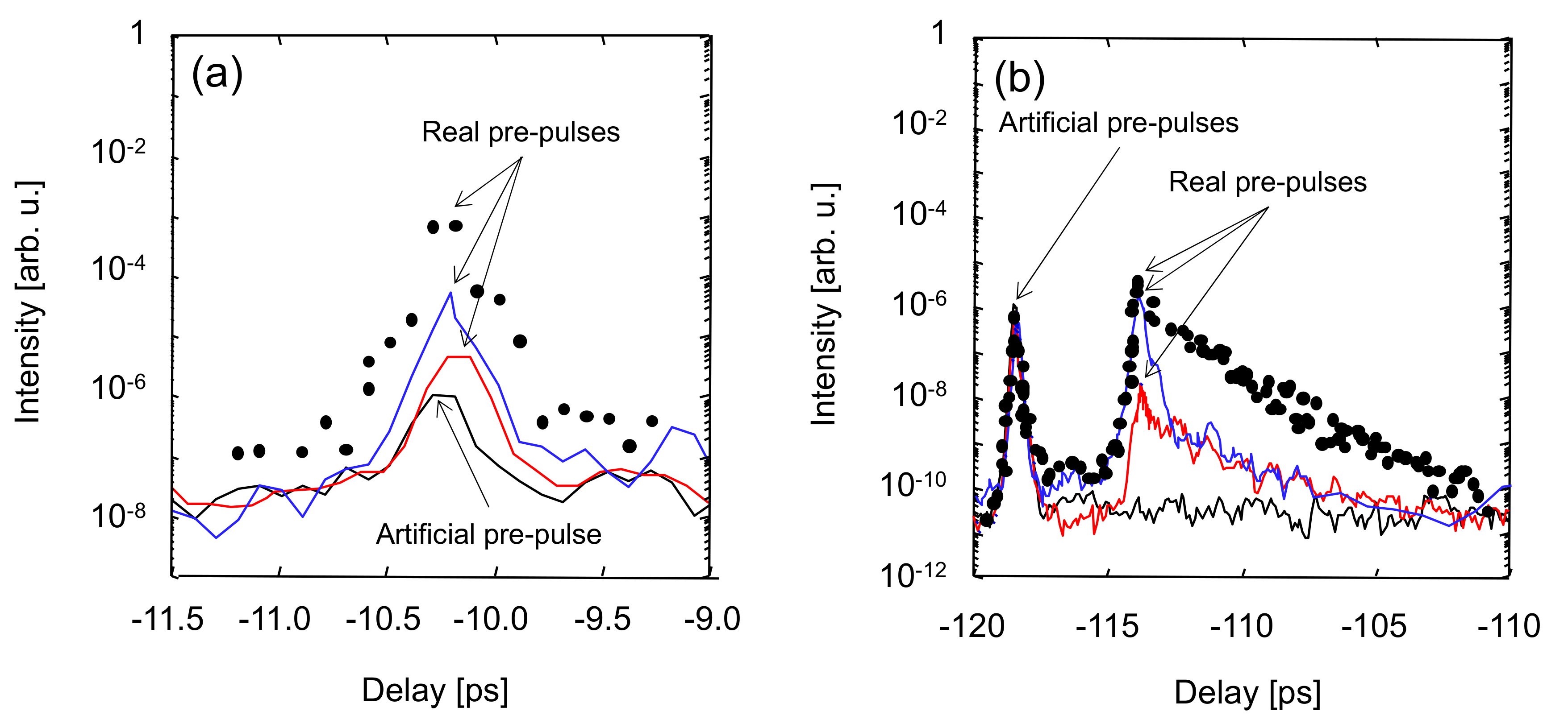
Figure 9 shows the temporal contrast of the pre-pulses by the post-pulses generated with the plane-parallel plates of ~1-mm (Figure 9a) and ~11.8-mm (Figure 9b) thickness. The measurements were performed with the output energies at the exit of the operating amplifiers of ~45 mJ, ~1.8 J, and ~26 J, resulting in different values for the B-integral of the pulses accumulated in the laser chain due to the different pulse intensities. The intensities of the beam before and after the compressor with the output energies at the exit of the operating amplifiers of ~45 mJ, ~1.8 J, and ~26 J were reasonably attenuated to be ~18 MW/cm2 and ~0.1 TW/cm2, respectively.
For the case of the plane-parallel plate of ~1-mm thickness, as can be seen from the black curve in Figure 9a, an artificial pre-pulse at ~10 ps before the main pulse appeared because of the post-pulse at ~10 ps after the main pulse due to the third-order cross-correlation process. The different real pre-pulse peak contrasts for the three different output energies of ~4.1 × 10⁻⁶ (red line), ~5.3 × 10⁻⁵ (blue line), and ~6.8 × 10⁻⁴ (black filled circles) are through nonlinear processes associated with the three different B-integral values of ~0.037, ~0.25, and ~0.85 rad, respectively. The B-integral values take into account all the optics in this experiment. The level of the real pre-pulse peak contrast was up to ~3 orders of magnitude higher than that of the artificial pre-pulse peak contrast, while keeping the post-pulse peak contrast of ~10−3. The observed rise of the real pre-pulse magnitude is explained by the accumulation of the nonlinear phase in the laser chain. The real pre-pulse peak contrasts for the three different output energies generated by the post-pulse can be evaluated [28] to be 4.6 × 10⁻⁷, 2.0 × 10⁻⁵, and 2.4 × 10⁻⁴. The artificial pre-pulse was not affected by the B-integral and the temporal contrast should be kept at ~10−6 even though the B-integral changed. The real pre-pulse is buried when the B-integral is small. The theoretical estimate fits the experimental data reasonably well. The magnitude of the real pre-pulse peak contrast rose monotonically with the increase of the B-integral values.
For the case of the pre-pulses from the plane-parallel plate of ~11.8-mm thickness, as shown in Figure 9b, three interesting features were found. First, the artificial pre-pulse at ~118 ps before the main pulse appeared because of the post-pulse at ~118 ps after the main pulse due to the third-order cross-correlation process, as shown in the black curve in Figure 9b. However, the exact position of the real pre-pulses in time did not coincide with the post-pulse at ~118 ps after main pulse. The real pre-pulse peak was delayed by ~4.8 ps to ~113.2 ps. Second, the real pre-pulses were greatly asymmetrically distorted and broadened. Third, the real pre-pulse peak contrast was drastically suppressed. Although the real pre-pulse contrast with a plate of ~1-mm thickness was degraded to ~6.8 × 10⁻⁴, that with ~11.8-mm thickness only reached ~3.8 × 10⁻⁶. The different real pre-pulse peak contrasts of ~1.8 × 10⁻⁸ (red line), ~2.0 × 10⁻⁶ (blue line), and ~3.8 × 10⁻⁶ (black filled circles) were through nonlinear processes associated with three different B-integral values of ~0.037, ~0.25, and ~0.85 rad, respectively. In the same manner, the real pre-pulse peak contrast by the post-pulse can be estimated [28] to be 4.6 × 10⁻⁷, 2.0 × 10⁻⁵, and 2.4 × 10⁻⁴. The artificial pre-pulse was not affected by the B-integral and the temporal contrast should be kept at ~10−6 even though the B-integral changed. The real pre-pulse is buried when the B-integral is small. The real pre-pulse peak contrast measured with ~11.8-mm thickness was much lower, compared with the theoretical prediction, by ~2 orders of magnitude. The magnitude of the real pre-pulse peak contrast was degraded and the pulse duration of the delayed real pre-pulse was broadened with the increase of the B-integral values. The degradation of the real pre-pulse peak contrast with ~11.8-mm thickness was much smaller than that with ~1-mm thickness.
In this investigation, the critical elements for the B-integral were the power and booster amplifiers, because the power amplifier consisted of two windows and a Ti:sapphire crystal and the booster amplifier was even thicker. When we install the plasma mirror systems, we can remove the Faraday isolator to prevent the back-reflection light from the target. However, in this investigation the reduction of the B-integral value by the Faraday rotator was calculated to be ~0.0128 and did not, therefore, contribute significantly to the total B-integral. Although the B-integral value can be reduced with a larger-diameter beam and lower-fluence operation, this requires a major modification of the laser system. Thus, it is hard to reduce the B-integral value without any major change to the original system.
The experiment with the a ~1-mm thickness, plane-parallel plate confirms that the real pre-pulse generation was due to the nonlinearity of the refractive index and the real pre-pulse peak contrast agrees reasonably well with the theoretical prediction [28]. However, in the experiment with the a ~11.8-mm thickness, plane-parallel plate, the real pre-pulses were delayed and asymmetrically broadened. This mechanism is not understood yet. Although the post-pulses generated by the ~1-mm thickness, plane-parallel plate almost fully overlap, approximately 98%, with the main pulse before recompression, the post-pulses generated by the ~11.8-mm thickness, plane-parallel plate only overlapped partially, ~75%. The smaller overlap percentage means smaller interference, resulting in a narrower spectral bandwidth modulation and, due to its nonlinear nature, smaller energy transfer to generate real pre-pulses. Therefore, the real pre-pulses with broader pulse duration and lower peak intensities were generated. The dispersion of these real pre-pulses accumulated in the laser chain with many optics was completely different from that of the main pulse. Thus, these real pre-pulses were not allowed to compress to the same pulse duration of the main pulse because the compressor was set and optimized for the main pulse dispersion. The asymmetrically distorted, real pre-pulse shape, i.e., the significantly post-foot starting at peak intensities indicative of positive, higher odd-order dispersion, is also likely in combination with self-phase modulation. The modulated part had shorter wavelength components, which were later in time in our positive, chirped-laser system. Therefore, the generated, real pre-pulses were delayed in time. In order to fully understand and evaluate the real pre-pulses generated by post-pulses through the nonlinear process, additional and further research, both theoretical and experimental, is required and will be reported in future work.

3.2. Temporal Contrast Improvement

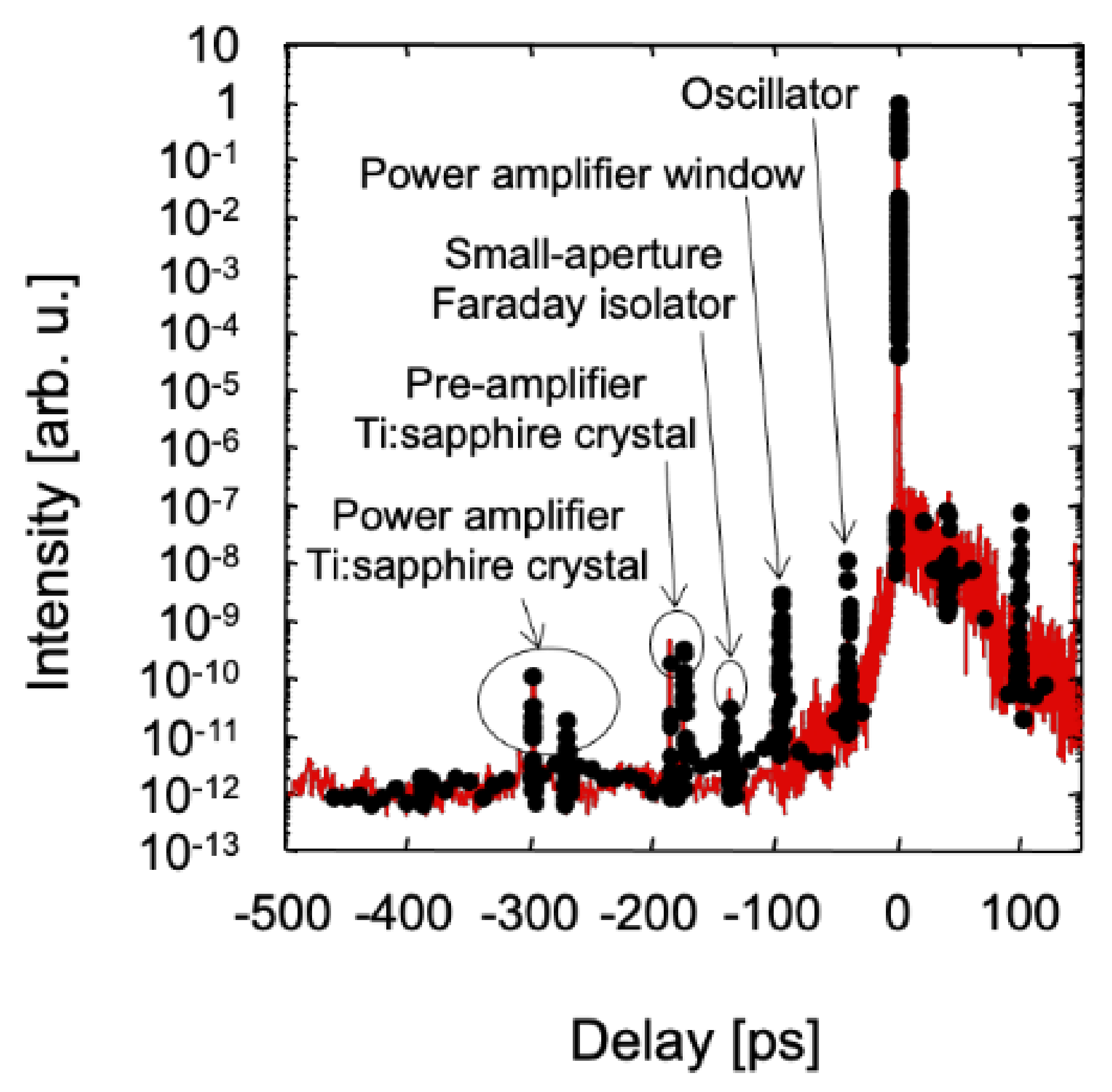
Figure 10 shows the temporal contrast of the J-KAREN-P laser system. The measurement was performed with output energies of ~1 J and ~10 J. By means of the above investigation of pre-pulses caused by post-pulses generated with plane-parallel plates, we could identify the artificial and real pre-pulses in the J-KAREN-P laser system. We clearly distinguished that the pre-pulses at ~298 and ~186 ps before the main were artificial in the third-order, cross-correlation process by post-pulses created through internal reflection in the Ti:sapphire crystals in the power and pre-amplifiers. The pre-pulses at ~270, ~175, ~137, ~96, and ~40 ps before the main pulse were real by post-pulses created in the Ti:sapphire crystal in the power amplifier, Ti:sapphire crystal in the pre-amplifier, small-aperture Faraday isolator placed before the OPCPA pre-amplifier, windows in the vacuum chamber, and the optics inside the oscillator, respectively. The residual reflectance of the anti-reflection coatings on the Ti:Sapphire pre-amplifier and power amplifier crystals, on the power amplifier window, and on the Faraday isolator were in the range of 0.3 to 0.8% for 770 to 800 nm in our system.
The only way to remove the real pre-pulses caused by post pulses is the complete removal of the post-pulses. We, therefore, fabricated wedged optical components, specifically Ti:sapphire crystals and windows, which completely avoid the creation of co-propagating post-pulses. The specification of the anti-reflection coatings for the wedged optics was the same as that for the non-wedged optics. The angular dispersion was self-compensated by the two-pass and four-pass amplifier geometries. We have theoretically and experimentally verified that there was no degradation of the focused spot after introducing the wedged optical components.
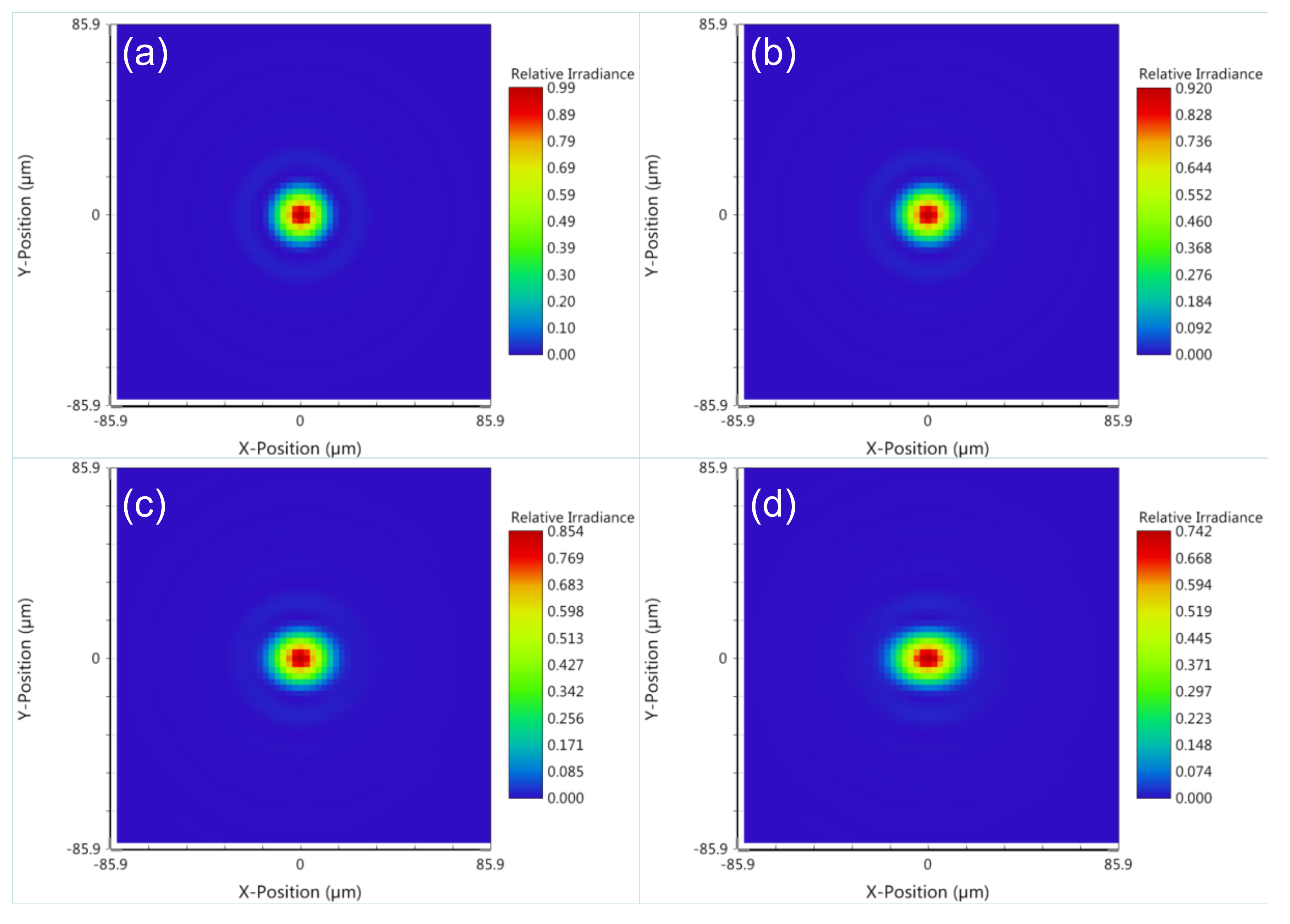
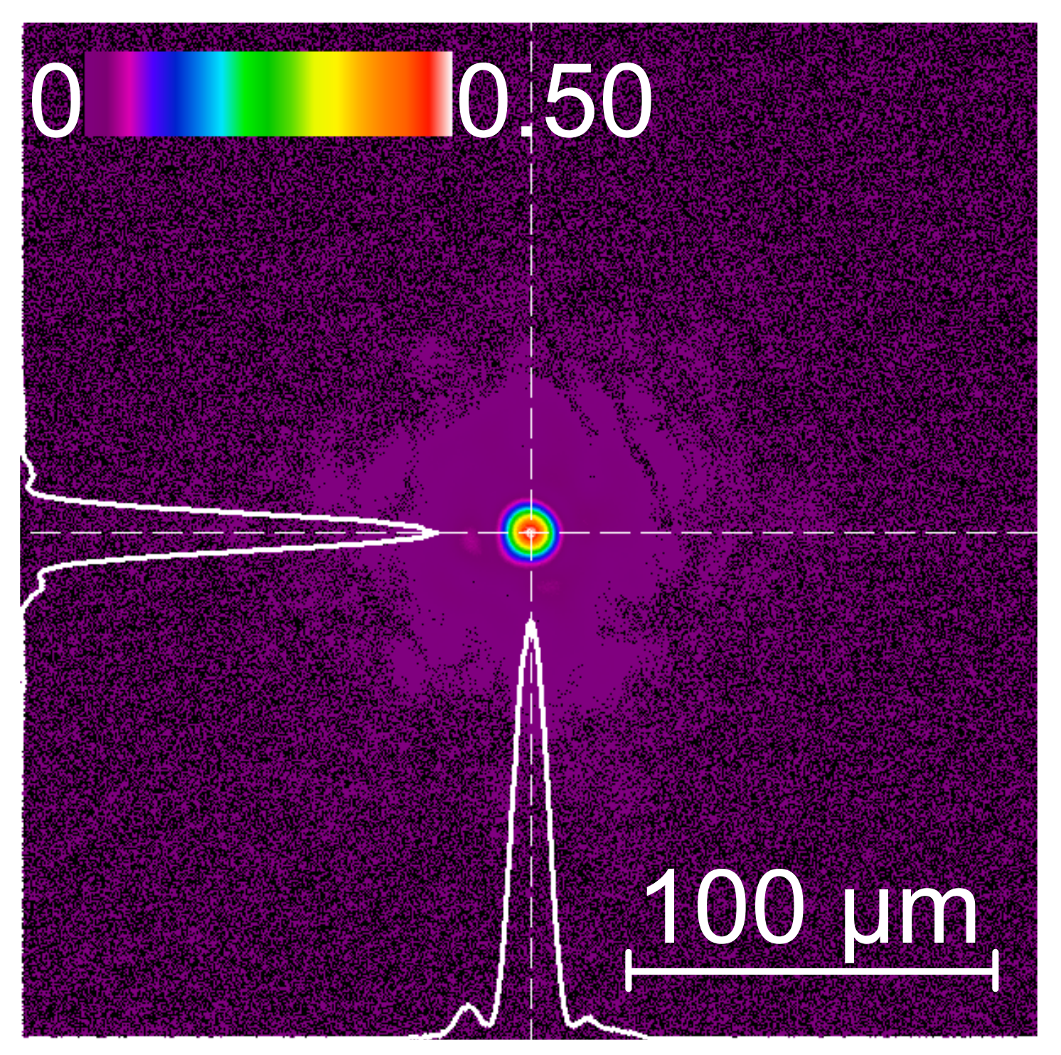
To estimate the effect of the wedged crystals and windows on the focusability, we modeled all amplifiers with the Zemax software (Zemax LLC, OpticStudio 16.5 professional Edition, Washington, WA, USA). Examples of the calculated spots for the BA1 crystal wedge of 0.2, 0.5, 0.7, and 1.0° are shown in Figure 11. Based on these models, we selected crystal wedges of 0.5° and implemented them in the laser. An example of the resulting focal spot is shown in Figure 12. The focusability remained quite good, similar to our previous results [24] obtained without the wedges. To further confirm the absence of the angular chirp, we compared the full-bandwidth focal spot with a spot measured with a narrow-band pass filter. The average ratio of the full-bandwidth Strehl ratio to the narrow-band one was 0.969 ± 0.014, where the uncertainty was the standard error due to the shot-to-shot fluctuations (134 shots for full bandwidth and 139 for narrow band).
The real pre-pulse at ~40 ps before the main pulse came from the commercial oscillator and was, therefore, difficult to remove immediately, although it could be suppressed by replacing a specially designed homemade oscillator or by using plasma mirrors.
Figure 13a shows an example of an artificial pre-pulse and the shifted, real pre-pulse from the J-KAREN-P Ti:sapphire pre-amplifier before it was replaced with a wedged crystal. The artificial pulse was at ~186 ps before the main pulse and the peak of the real pre-pulse generated by post-pulse was delayed by ~11 ps to ~175 ps before the main pulse, with a greatly distorted, asymmetric, broadened temporal shape. This behavior was very similar to the pre-pulse caused by post-pulse investigation above with a ~11.8-mm-thick, plane-parallel plate. In our investigation, the delay between the artificial and real pre-pulses did not depend on the B-integral. It was found experimentally that the delay increased as a quadratic function of the optical path length, which was the product of the thickness and the refractive index of the optical component. Figure 13b shows the removal of the real pre-pulse after replacement with the new wedged Ti:sapphire pre-amplifier crystal. As can be seen in Figure 13b, the artificial and the real pre-pulses were removed.
After introducing the wedged optical components, the temporal contrast was again measured with ~1 and ~10 J output energies. The small-aperture Faraday isolator placed before the OPCPA pre-amplifier was removed because the system provided sufficient optical isolation to avoid back-reflected light. As can be seen from Figure 14, all real pre-pulses other than the real pre-pulse at ~40 ps before the main pulse were removed.

4. Applications with the J-KAREN-P Laser System

We briefly introduce some experimental results obtained with the J-KAREN-P laser system and prospects for high-field science experiments. One of the most attractive applications with ultra-short, ultra-high intensity lasers is laser-driven particle acceleration, featuring high accelerating electric fields, short acceleration distance, and short bunch lengths compared to rf (radio frequency) accelerators. Proton [48] and electron acceleration using the J-KAREN-P laser system is under investigation. More than 50 MeV (Mega electron Volt) protons [49,50] were obtained with a laser intensity of ~1021 W/cm2. At the laser intensity of 5 × 10²¹ W/cm2, the effect of using a small focus spot on electron heating and proton acceleration were investigated [51], and highly charged high-Z ions were accelerated to over GeV (Giga electron Volt) energies. Laser-plasma acceleration has the possibility to downsize conventional large-accelerator systems. A unique system was proposed to accelerate short-lived heavy ions dedicated for the study of exotic nuclei [52,53]. In particular, the generation of carbon ions with energy 4 MeV/n and 10% energy bandwidth is being studied as an ion source for an injector for a future cancer radiotherapy accelerator at QST. The generation of high-energy, highly charged, heavy ion beams was also investigated, with a focus on understanding the ionization mechanism, which is extremely important for the control of laser-driven heavy ion beams [54]. Electron acceleration is also being studied with a goal of downsizing X-ray free-electron laser facilities. Currently, experiments are ongoing to generate GeV electron beams from 1–2-cm gas jet targets with a focused irradiance of 1020 W/cm2. Experiments on high-order harmonics from relativistic singularities [55,56,57,58,59], on high-repetition-rate multi-MeV, pure proton beam generation from micron-scale hydrogen cluster targets [60,61,62,63], and on X-ray spectroscopy of laser–plasma interaction in the ultra-relativistic regime [64,65] are also in progress. Future prospects for high-field science include the testing of quantum electrodynamics (QED), which will be made possible even for a small facility such as KPSI, QST. One of the QED processes that can occur is the generation of electron–positron pairs from the vacuum by colliding either strongly focused J-KAREN-P laser pulses or frequency-upshifted pulses generated by relativistic flying mirrors produced by the J-KAREN-P laser in plasma with high energy GeV electron beams [66].

5. Conclusions

Ultra-high intensity lasers have now become important scientific tools to study previously unobtainable extreme states of matter. Understanding and controlling the extreme conditions produced by laser–matter interactions has led to a wide variety of experiments and new potential basic science and industrial applications being pursued, necessitating the development of high-power laser capability. The J-KAREN-P laser system at QST has been constructed with in-house technologies and has provided high-intensity laser pulses with high spatiotemporal quality for accelerating charged particles, generating ultra-short, high-energy photons and others. This laser system is known as one of the leading facilities in the optical community [10,13]. Multi-petawatt laser systems have been demonstrated and 100-petawatt-class lasers have been proposed and are even under construction. Such lasers will allow us to enrich our understanding of fundamental physics in the ultra-relativistic regime.

Author Contributions

Conceptualization, H.K., A.S.P., M.N., Y.F. and M.K.; methodology, H.K.; software, N.P.D. and H.K.; validation, K.H., N.N., J.K.K., and M.K.; formal analysis, A.S.P. and T.Z.E.; investigation, H.K., A.S.P., M.N., Y.F., A.S., A.K., Y.M., K.O., K.K. (Kotaro Kondo), H.S., M.K., S.B., T.Z., T.P., K.Z. and U.S.; writing—Original draft preparation, H.K.; writing—Review and editing, H.K., A.S.P., M.N., Y.F., N.P.D. and J.K.K.; supervision, H.K.; project administration, K.K. (Kiminori Kondo), and U.S. All authors have read and agreed to the published version of the manuscript.

Funding

This research was funded by the Japan Society for the Promotion of Science (grant numbers: JP 15F15772, JP 16H03911, JP 16K05506, JP 19H00669, JP 20H01882), Precursory Research for Embryonic Science and Technology (grant number: JPMJPR16P9), Japan Science and Technology Agency (grant number: PRESTOJPMJPR16P9), QST President’s Strategic Grant (QST International Research Initiative (AAA98), and Creative Research (ABACS)).

Acknowledgments

The authors acknowledge contributions by the Kansai Photon Science Institute staff at the National Institutes for Quantum and Radiological Science. One of the authors, H. Kiriyama, would like to thank James Norby, Continuum (Amplitude Laser brand), for his significant contribution toward the excellent design, implementation, and performance of the OPCPA pump laser, and fruitful discussions and assistance with this paper.

Conflicts of Interest

The authors declare no conflict of interest.

References

  1. Backus, S.; Durfee, C.G., III; Murnane, M.M.; Kapteyn, H.C. High power ultrafast lasers. Rev. Sci. Instrum. 1998, 69, 1207–1223. [Google Scholar] [CrossRef]
  2. McClung, F.J.; Hellwarth, R. Giant optical pulsations from Ruby. J. Appl. Phys. 1962, 33, 828–829. [Google Scholar] [CrossRef]
  3. Mocker, H.W.; Collins, R.J. Mode competition and self-locking effects in a Q-switched ruby laser. Appl. Phys. Lett. 1965, 7, 270–273. [Google Scholar] [CrossRef]
  4. de Maria, A.J.; Stetser, D.A.; Heynau, H. Self mode-locking of lasers with saturable absorbers. Appl. Phys. Lett. 1966, 7, 174–176. [Google Scholar] [CrossRef]
  5. Strickland, D.; Mourou, G. Compression of amplified chirped optical pulses. Opt. Commun. 1985, 56, 219–221. [Google Scholar]
  6. Moulton, P.F. Spectroscopic and laser characteristics of Ti:Al2O3. J. Opt. Soc. Am. B 1986, 3, 125–133. [Google Scholar] [CrossRef]
  7. Yu, T.J.; Lee, S.K.; Sung, J.H.; Yoon, J.W.; Jeong, T.M.; Lee, J. Generation of high-contrast, 30 fs, 1.5 PW laser pulses from chirped-pulse amplification Ti: Sapphire laser. Opt. Express 2012, 20, 10807–10815. [Google Scholar] [CrossRef]
  8. Laux, S.; Lureau, F.; Radier, C.; Chalus, O.; Caradec, F.; Casagrande, O.; Pourtal, E.; Simon-Boisson, C.; Soyer, F.; Lebarny, P. Suppression of parasitic lasing in high energy, high repetition rate Ti: Sapphire laser amplifiers. Opt. Lett. 2012, 37, 1913–1915. [Google Scholar] [CrossRef]
  9. Kiriyama, H.; Shimomura, T.; Sasao, H.; Nakai, Y.; Tanoue, M.; Kondo, S.; Kanazawa, S.; Pirozhkov, A.S.; Mori, M.; Fukuda, Y.; et al. Temporal contrast enhancement of petawatt-class laser pulses. Opt. Lett. 2012, 37, 3363–3365. [Google Scholar] [CrossRef]
  10. Danson, C.; Hillier, D.; Hopps, N.; Neely, D. Petawatt class lasers worldwide. High Power Laser Sci. Eng. 2015, 3, e3. [Google Scholar] [CrossRef]
  11. Jeong, T.M.; Lee, J. Femtosecond petawatt laser. Ann. Phys. 2014, 526, 157–172. [Google Scholar] [CrossRef]
  12. Yakovlev, I.V. Stretchers and compressors for ultra-high power laser systems. Quantum Electron. 2014, 44, 393–414. [Google Scholar] [CrossRef]
  13. Danson, C.N.; Haefner, C.; Bromage, J.; Butcher, T.; Chanteloup, J.-C.F.; Chowdhury, E.A.; Galvanauskas, A.; Gizzi, L.A.; Hein, J.; Hillier, D.I.; et al. Petawatt and exawatt class lasers worldwide. High Power Laser Sci. Eng. 2019, 7, e54. [Google Scholar] [CrossRef]
  14. Sung, J.H.; Lee, H.W.; Yoo, J.Y.; Yoon, J.W.; Lee, C.W.; Yang, J.M.; Son, Y.J.; Jang, Y.H.; Lee, S.K.; Nam, C.H. 4.2 PW, 20 fs Ti: Sapphire laser at 0.1 Hz. Opt. Lett. 2017, 42, 2058–2061. [Google Scholar] [CrossRef] [PubMed]
  15. Center for Advanced Laser Applications. Available online: http://www.cala-laser.de (accessed on 28 May 2020).
  16. Li, W.; Gan, Z.; Yu, L.; Wang, C.; Liu, Y.; Guo, Z.; Xu, L.; Xu, M.; Hang, Y.; Xu, Y.; et al. 339  J high-energy Ti: Sapphire chirped-pulse amplifier for 10  PW laser facility. Opt. Lett. 2018, 43, 5681–5684. [Google Scholar] [CrossRef] [PubMed]
  17. eli Nuclear Physics. Available online: https://www.eli-np.ro (accessed on 28 May 2020).
  18. Wang, Y.; Wang, S.; Rockwood, A.; Luther, B.M.; Hollinger, R.; Curtis, A.; Calvi, C.; Menoni, C.S.; Rocca, J.J. 0.85 PW laser operation at 3.3 Hz and high-contrast ultrahigh-intensity λ = 400 nm second-harmonic beamline. Opt. Lett. 2017, 42, 3828–3831. [Google Scholar] [CrossRef] [PubMed]
  19. eli Beamlines. Available online: https://www.eli-beams.eu/facility/lasers/laser-3-hapls-1-pw-30-j-10-hz/ (accessed on 28 May 2020).
  20. Dubietis, A.; Jonusauskas, G.; Piskarskas, A. Powerful femtosecond pulse generation by chirped and stretched pulse parametric amplification in BBO crystal. Opt. Commun. 1992, 88, 437–440. [Google Scholar] [CrossRef]
  21. Ross, I.N.; Matousek, P.; Towrie, M.; Langley, A.J.; Collier, J.L. The prospects for ultrashort pulse duration and ultrahigh intensity using optical parametric chirped pulse amplifiers. Opt. Commun. 1997, 144, 125–133. [Google Scholar] [CrossRef]
  22. Zeng, X.; Zhou, K.; Zuo, Y.; Zhu, Q.; Su, J.; Wang, X.; Wang, X.; Huang, X.; Jiang, X.; Jiang, D.; et al. Multi-petawatt laser facility fully based on optical parametric chirped-pulse amplification. Opt. Lett. 2017, 42, 2014–2017. [Google Scholar] [CrossRef]
  23. Marriage of a 20keV Superconducting XFEL with a 100PW Laser. Available online: https://spie.org/news/marriage-of-a-20kev-superconducting-xfel-with-a-100pw-laser (accessed on 28 May 2020).
  24. Pirozhkov, A.S.; Fukuda, Y.; Nishiuchi, M.; Kiriyama, H.; Sagisaka, A.; Ogura, K.; Mori, M.; Kishimoto, M.; Sakaki, H.; Dover, N.P.; et al. Approaching the diffraction-limited, bandwidth-limited Petawatt. Opt. Express 2017, 25, 20486–20501. [Google Scholar] [CrossRef]
  25. Guo, Z.; Yu, L.; Wang, J.; Wang, C.; Liu, Y.; Gan, Z.; Li, W.; Leng, Y.; Liang, X.; Li, R. Improvement of the focusing ability by double deformable mirrors for 10-PW-level Ti: Sapphire chirped pulse amplification laser system. Opt. Express 2018, 26, 26776–26786. [Google Scholar] [CrossRef] [PubMed]
  26. Yoon, J.W.; Jeon, C.; Shin, J.; Lee, S.K.; Lee, H.W.; Choi, I.W.H.; Kim, T.; Sung, J.H.; Nam, C.H. Achieving the laser intensity of 5.5 × 10²² W/cm2 with a wavefront-corrected multi-PW laser. Opt. Express 2019, 27, 20412–20420. [Google Scholar] [CrossRef]
  27. Ivanov, V.V.; Maksimchuk, A.; Mourou, G. Amplified spontaneous emission in a Ti: Sapphire regenerative amplifier. Appl. Opt. 2003, 42, 7231–7234. [Google Scholar] [CrossRef] [PubMed]
  28. Didenko, N.V.; Konyashchenko, A.V.; Lutsenko, A.P.; Tenyakov, S.Y. Contrast degradation in a chirped-pulse amplifier due to generation of prepulses by postpulses. Opt. Express 2008, 16, 3178–3190. [Google Scholar] [CrossRef] [PubMed]
  29. Khodakovskiy, N.; Kalashinikov, M.; Gontier, E.; Falcoz, F.; Paul, P.-M. Degradation of picosecond temporal contrast of Ti: Sapphire lasers with coherent pedestals. Opt. Lett. 2016, 41, 4441–4444. [Google Scholar] [CrossRef] [PubMed]
  30. Kiriyama, H.; Mashiba, Y.; Miyasaka, Y.; Asakawa, M.R. Random spectral phase noise effect on the temporal contrast of ultra-high intensity laser pulse. Rev. Laser Eng. 2018, 46, 142–144. [Google Scholar]
  31. Thaury, C.; Quéré, F.; Geindre, J.-P.; Levy, A.; Ceccotti, T.; Monot, P.; Bougeard, M.; Réau, F.; d’Oliveira, P.; Audebert, P.; et al. Plasma mirrors for ultrahigh-intensity optics. Nat. Phys. 2007, 3, 424–429. [Google Scholar] [CrossRef]
  32. Kalashnikov, M.P.; Risse, E.; Schönnagel, H.; Sandner, W. Double chirped-pulse-amplification laser: A way to clean pulses temporally. Opt. Lett. 2005, 30, 923–925. [Google Scholar] [CrossRef]
  33. Jullien, A.; Albert, O.; Burgy, F.; Hamoniaux, G.; Rousseau, J.-P.; Chambaret, J.-P.; Augé-Rochereau, F.; Chériaux, G.; Etchepare, J.; Minkovski, N.; et al. 10−10 temporal contrast for femtosecond ultraintense lasers by cross-polarized wave generation. Opt. Lett. 2005, 30, 920–922. [Google Scholar] [CrossRef] [Green Version]
  34. Yu, L.; Xu, Y.; Liu, Y.; Li, Y.; Li, S.; Liu, Z.; Li, W.; Wu, F.; Yang, X.; Yang, Y.; et al. High-contrast front end based on cascaded XPWG and femtosecond OPA for 10-PW-level Ti: Sapphire laser. Opt. Express 2018, 26, 2625–2633. [Google Scholar] [CrossRef]
  35. Schimpf, D.N.; Seise, E.; Limpert, J.; Tünnermann, A. Decrease of pulse-contrast in nonlinear chirped-pulse amplification systems due to high-frequency spectral phase ripples. Opt. Express 2008, 16, 8876–8886. [Google Scholar] [CrossRef] [PubMed]
  36. Keppler, S.; Hornung, M.; Bodefeld, R.; Kahle, M.; Hein, J.; Kaluza, M.C. All-reflective, highly accurate polarization rotator for high-power short-pulse laser systems. Opt. Express 2018, 20, 20742–20747. [Google Scholar] [CrossRef] [PubMed]
  37. Schanz, V.A.; Brabetz, C.; Posor, D.J.; Reemts, D.; Roth, M.; Bagnoud, V. High dynamic range, large temporal domain laser pulse measurement. Appl. Phys. B 2019, 125, 61. [Google Scholar] [CrossRef]
  38. Kiriyama, H.; Miyasaka, Y.; Sagisaka, A.; Ogura, K.; Nishiuchi, M.; Pirozhkov, A.S.; Fukuda, Y.; Kando, M.; Kondo, K. Experimental investigation on the temporal contrast of pre-pulses by post-pulses in a petawatt laser facility. Opt. Lett. 2020, 45, 1100–1103. [Google Scholar] [CrossRef]
  39. Kiriyama, H.; Mori, M.; Pirozhkov, A.S.; Ogura, K.; Sagisaka, A.; Kon, A.; Esirkepov, T.Z.; Hayashi, Y.; Kotaki, H.; Kanasaki, M.; et al. High-contrast, high-intensity petawatt-class laser and applications. IEEE J. Sel. Top. Quantum Electron. 2015, 21, 1601118. [Google Scholar] [CrossRef]
  40. Kiriyama, H.; Pirozhkov, A.S.; Nishiuchi, M.; Fukuda, Y.; Ogura, K.; Sagisaka, A.; Miyasaka, Y.; Mori, M.; Sakaki, H.; Dover, N.P.; et al. High-contrast high-intensity repetitive petawatt laser. Opt. Lett. 2018, 43, 2595–2598. [Google Scholar] [CrossRef]
  41. Kiriyama, H.; Pirozhkov, A.S.; Nishiuchi, M.; Fukuda, Y.; Ogura, K.; Sagisaka, A.; Miyasaka, Y.; Sakaki, H.; Dover, N.P.; Kondo, K.; et al. Status and progress of the J-KAREN-P high intensity laser system at QST. High Energy Density Phys. 2020, 36, 100771. [Google Scholar] [CrossRef]
  42. Cheriaux, G.; Rousseau, P.; Salin, F.; Chambaret, J.P.; Walker, B.; Dimauro, L.F. Aberration-free stretcher design for ultrashort-pulse amplification. Opt. Lett. 1996, 21, 414–416. [Google Scholar] [CrossRef]
  43. Kiriyama, H.; Mori, M.; Nakai, Y.; Shimomura, T.; Tanoue, M.; Akutsu, A.; Kondo, S.; Kanazawa, S.; Okada, H.; Motomura, T.; et al. High-contrast, high-intensity laser pulse generation using a nonlinear preamplifier in a Ti: Sapphire laser system. Opt. Lett. 2008, 33, 645–647. [Google Scholar] [CrossRef]
  44. Kiriyama, H.; Mori, M.; Nakai, Y.; Yamamoto, Y.; Tanoue, M.; Akutsu, A.; Shimomura, T.; Kondo, S.; Kanazawa, S.; Daido, H.; et al. High-energy, high-contrast, multiterawatt laser pulses by optical parametric chirped-pulse amplification. Opt. Lett. 2007, 32, 2315–2317. [Google Scholar] [CrossRef]
  45. Hello, P.; Man, C.N. Design of a low-loss off-axis beam expander. Appl. Opt. 1996, 35, 2534–2536. [Google Scholar] [CrossRef] [PubMed]
  46. Frantz, L.M.; Nodvik, J.S. Theory of pulse propagation in a laser amplifier. J. Appl. Phys. 1963, 34, 2346–2349. [Google Scholar] [CrossRef]
  47. Oksenhendler, T.; Courdreau, S.; Forget, N.; Crozatier, V.; Grabielle, S.; Herzog, R.; Gobert, O.; Kaplan, D. Self-referenced spectral interferometry. Appl. Phys. B 2010, 99, 7–12. [Google Scholar] [CrossRef]
  48. Daido, H.; Nishiuchi, M.; Pirozhkov, A.S. Review of laser-driven ion sources and their applications. Rep. Prog. Phys. 2012, 75, 056401–056471. [Google Scholar] [CrossRef]
  49. Nishiuchi, M.; Kiriyama, H.; Sakaki, H.; Dover, N.P.; Kondo, K.; Pirozhkov, A.S.; Sagisaka, A.; Fukuda, Y.; Nishitani, K.; Miyahara, T.; et al. Ion acceleration experiment with the high intensity, high contrast J-KAREN-P laser system. Rev. Laser Eng. 2018, 46, 145–147. [Google Scholar]
  50. Dover, N.P.; Nishiuchi, M.; Sakaki, H.; Kondo, K.; Lowe, H.F.; Alkhimova, M.A.; Ditter, E.J.; Ettlinger, O.C.; Faenov, A.Y.; Hata, M.; et al. Demonstration of repetitive energetic proton generation by ultra-intense laser interaction with a tape target. High Energy Density Phys. 2020, 37, 100847. [Google Scholar] [CrossRef]
  51. Dover, N.P.; Nishiuchi, M.; Sakaki, H.; Kondo, K.; Alkhimova, M.A.; Faenov, A.; Hata, M.; Iwata, N.; Kiriyama, H.; Koga, J.; et al. Effect of Small Focus on Electron Heating and Proton Acceleration in Ultrarelativistic Laser-Solid Interactions. Phys. Rev. Lett. 2020, 124, 084802-1–084802-7. [Google Scholar]
  52. Nishiuchi, M.; Sakaki, H.; Esirkepov, T.Z.; Nishio, K.; Pikuz, T.A.; Faenov, A.Y.; Skobelev, I.Y.; Orlandi, R.; Sako, H.; Pirozhkov, A.S.; et al. Acceleration of highly charged GeV Fe ions from a low-Z substrate by intense femtosecond laser. Phys. Plasmas 2015, 22, 033107-1–033107-8. [Google Scholar] [CrossRef]
  53. Nishiuchi, M.; Sakaki, H.; Esirkepov, T.Z.; Nishio, K.; Pikuz, T.A.; Faenov, A.Y.; Skobelev, I.Y.; Orlandi, R.; Pirozhkov, A.S.; Sagisaka, A.; et al. Towards a novel laser-driven method of exotic nuclei extraction−acceleration for fundamental physics and technology. Plasma Phys. Rep. 2016, 42, 327–337. [Google Scholar] [CrossRef]
  54. Nishiuchi, M.; Dover, N.P.; Hata, M.; Sakaki, H.; Kondo, K.; Lowe, H.F.; Miyahara, T.; Kiriyama, H.; Koga, J.K.; Iwata, N.; et al. Dynamics of Laser-driven Heavy Ion Acceleration Clarified by Ion Charge States. Phys. Rev. Res. 2020, 2, 033081. [Google Scholar] [CrossRef]
  55. Pirozhkov, A.S.; Kando, M.; Esirkepov, T.Z.; Gallegos, P.; Ahmed, H.; Ragozin, E.N.; Faenov, A.Y.; Pikuz, T.A.; Kawachi, T.; Sagisaka, A.; et al. Soft-X-Ray Harmonic Comb from Relativistic Electron Spikes. Phys. Rev. Lett. 2012, 108, 135004. [Google Scholar] [CrossRef] [PubMed] [Green Version]
  56. Pirozhkov, A.S.; Kando, M.; Esirkepov, T.Z.; Gallegos, P.; Ahmed, H.; Ragozin, E.N.; Faenov, A.Y.; Pikuz, T.A.; Kawachi, T.; Sagisaka, A.; et al. High order harmonics from relativistic electron spikes. New J. Phys. 2014, 16, 093003. [Google Scholar] [CrossRef]
  57. Pirozhkov, A.S.; Esirkepov, T.Z.; Pikuz, T.A.; Faenov, A.Y.; Ogura, K.; Hayashi, Y.; Kotaki, H.; Ragozin, E.N.; Neely, D.; Kiriyama, H.; et al. Burst intensification by singularity emitting radiation in multi-stream flows. Sci. Rep. 2017, 7, 17968. [Google Scholar] [CrossRef] [PubMed]
  58. Pirozhkov, A.S.; Esirkepov, T.Z.; Pikuz, T.A.; Faenov, A.Y.; Sagisaka, A.; Ogura, K.; Hayashi, Y.; Kotaki, H.; Ragozin, E.N.; Neely, D.; et al. Laser Requirements for High-Order Harmonic Generation by Relativistic Plasma Singularities. Quantum Beam Sci. 2018, 2, 7. [Google Scholar] [CrossRef] [Green Version]
  59. Sagisaka, A.; Ogura, K.; Esirkepov, T.Z.; Neely, D.; Pikuz, T.A.; Koga, J.K.; Fukuda, Y.; Kotaki, H.; Hayashi, Y.; Gonzalez-Izquierdo, B.; et al. Observation of Burst Intensification by Singularity Emitting Radiation generated from relativistic plasma with a high-intensity laser. High Energy Density Phys. 2020, 36, 100751. [Google Scholar] [CrossRef]
  60. Jinno, S.; Tanaka, H.; Matsui, R.; Kanasaki, M.; Sakaki, H.; Kando, M.; Kondo, K.; Sugiyama, A.; Uesaka, M.; Kishimoto, Y.; et al. Characterization of micron-size hydrogen clusters using Mie scattering. Opt. Express 2017, 25, 18774–18783. [Google Scholar] [CrossRef]
  61. Jinno, S.; Kanasaki, M.; Uno, M.; Matsui, R.; Uesaka, M.; Kishimoto, Y.; Fukuda, Y. Micron-size hydrogen cluster target for laser-driven proton acceleration. Plasma Phys. Control. Fusion 2018, 60, 044021. [Google Scholar] [CrossRef]
  62. Matsui, R.; Fukuda, Y.; Kishimoto, Y. Quasimonoenergetic proton bunch acceleration driven by hemispherically converging collisionless shock in a hydrogen cluster coupled with relativistically induced transparency. Phys. Rev. Lett. 2019, 122, 014804-1–014804-6. [Google Scholar] [CrossRef]
  63. Asai, A.; Kanasaki, M.; Jinno, S.; Kitagawa, N.; Shutoh, N.; Kodaira, S.; Yamauchi, T.; Oda, K.; Morishima, K.; Fukuda, Y. Application of nuclear emulsions for the identi cation of multi-MeV protons in laser ion acceleration experiments. High Energy Density Phys 2019, 32, 44–50. [Google Scholar] [CrossRef]
  64. Faenov, A.Y.; Colgan, J.; Hansen, S.B.; Zhidkov, A.; Pikuz, T.A.; Nishiuchi, M.; Pikuz, S.A.; Skobelev, I.Y.; Abdallah, J.; Sakaki, H.; et al. Nonlinear increase of X-ray intensities from thin foils irradiated with a 200 TW femtosecond laser. Sci. Rep. 2015, 5, 13436. [Google Scholar] [CrossRef] [Green Version]
  65. Alkhimova, M.A.; Faenov, A.Y.; Skobelev, I.Y.; Pikuz, T.A.; Nishiuchi, M.; Sakaki, H.; Pirozhkov, A.S.; Sagisaka, A.; Dover, N.P.; Ogura, K.; et al. High resolution X-ray spectra of stainless steel foils irradiated by femtosecond laser pulses with ultra-relativistic intensities. Opt. Express 2017, 25, 29501–29511. [Google Scholar] [CrossRef]
  66. Bulanov, S.V.; Esirkepov, T.Z.; Hayashi, Y.; Kando, M.; Kiriyama, H.; Koga, J.K.; Kondo, K.; Kotaki, H.; Pirozhkov, A.S.; Bulanov, S.S.; et al. On the design of experiments for the study of extreme field limits in the interaction of laser with ultrarelativistic electron beam. Nucl. Instrum. Methods A 2011, 660, 31–42. [Google Scholar] [CrossRef] [Green Version]
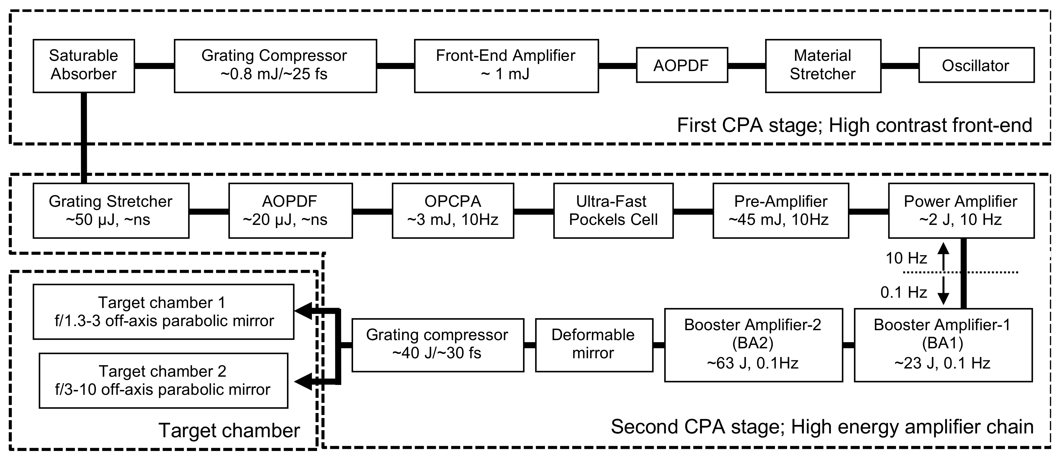
Figure 1. Schematic diagram of the J-KAREN-P laser system at KPSI, QST.
Crystals 10 00783 g001
Figure 2. Detailed OPCPA pre-amplifier layout. TFP, thin-film polarizer; HWP, half-wave plate; BDs, beam dumpers; IRTs, image relay telescopes; DMs, dichroic mirrors.
Crystals 10 00783 g002
Figure 3. (a) Representative measured temporal profile of the pump laser for the OPCPA pre-amplifier for broadband amplification. (b) Representative measured spectra of the seed (gray line) and output of the OPCPA pre-amplifier for the broadband amplification pumped by a temporally shaped laser (black line).
Crystals 10 00783 g003
Figure 4. Measured output energy of the OPCPA pre-amplifier for broadband amplification as a function of the energy of the pump laser.
Crystals 10 00783 g004
Figure 5. (a) Measured output energy of the final amplifier as a function of the energy of the pump laser. The theoretical curve is also shown. (b) Measured near-field spatial profile from the final amplifier.
Crystals 10 00783 g005
Figure 6. Representative measured spectra for the broadband amplification of the seed (gray line), output of the OPCPA pre-amplifier pumped by a temporally shaped laser (black line), the Ti:sapphire pre-amplifier (orange line), the power amplifier (green line), the booster amplifier 1 (blue line), and the booster amplifier 2 (red line).
Crystals 10 00783 g006
Figure 7. (a) Measured recompressed pulse profile. (b) Measured pulse width (FWHM) versus shot number.
Crystals 10 00783 g007
Figure 8. Representative J-KAREN-P laser wavefronts and corresponding calculated and measured spots. (a) Wavefront before the deformable mirror for a ~90-mm-diameter beam. (b) Wavefront before the compressor for a ~280-mm-diameter beam after aberration correction. (c) Calculated spot (PSF) corresponding to frame (a). (d) Measured at-focus spot (300 TW 280-mm-diameter beam after compressor attenuated with 10 wedges and focused with an f/1.3 OAP, measured in vacuum). In (c,d), the maxima correspond to the corresponding Strehl ratios.
Crystals 10 00783 g008
Figure 9. Measured pre-pulse contrast in the J-KAREN-P laser system with the plane-parallel plates of ~1 mm (a) and ~11.8 mm (b). The black line is for calibration (the plane-parallel plate is placed after the compressor). The red line, blue line, and black, filled circles are obtained with the output energies of ~45 mJ ~1.8 J, and ~26 J, respectively. These energies correspond to the B-integrals of ~ 0.037, ~ 0.25, and ~ 0.85 rad, respectively.
Crystals 10 00783 g009
Figure 10. Measured contrast of the J-KAREN-P laser system. The red line and black, filled circles were obtained with the output energies of ~1 J and ~10 J, respectively, showing identification of the artificial and real pre-pulses generated by the post-pulses.
Crystals 10 00783 g010
Figure 11. Zemax model of the BA1 amplifier with one of each of the following wedged crystals: Focal spot (polychromatic PSF) after an f = 1-m perfect lens. (a) Wedge = 0.2°, (b) wedge = 0.5°, (c) wedge = 0.7°, (d) wedge = 1.0°.
Crystals 10 00783 g011
Figure 12. Focal spot with wedged crystals measured after an f = 2.6-m, off-axis parabola. The Strehl ratio is 0.50.
Crystals 10 00783 g012
Figure 13. Representative measured pre-pulses in the J-KAREN-P laser system by the Ti:sapphire pre-amplifier crystal with (a) no wedge and (b) a small wedge angle.
Crystals 10 00783 g013
Figure 14. Measured contrast of the J-KAREN-P laser system with ~1 J (solid red line) and ~10 J (black, filled circles) output pulse energies by introducing wedged optics.
Crystals 10 00783 g014