Article

Understanding the Antipathogenic Performance of Nanostructured and Conventional Copper Cold Spray Material Consolidations and Coated Surfaces

by
Bryer C. Sousa
1,*,
Kristin L. Sundberg
2,
Matthew A. Gleason
1 and
Danielle L. Cote
1,*
1
Materials Science and Engineering, Worcester Polytechnic Institute, Worcester, MA 01609, USA
2
Raytheon Technologies, Waltham, MA 02451, USA
*
Authors to whom correspondence should be addressed.
Crystals 2020, 10(6), 504; https://doi.org/10.3390/cryst10060504
Submission received: 1 May 2020 / Revised: 9 June 2020 / Accepted: 10 June 2020 / Published: 12 June 2020

Abstract

:
The role of high strain rate and severe plastic deformation, microstructure, electrochemical behavior, surface chemistry and surface roughness were characterized for two copper cold spray material consolidations, which were produced from conventionally gas-atomized copper powder as well as spray-dried copper feedstock, during the course of this work. The motivation underpinning this work centers upon the development of a more robust understanding of the microstructural features and properties of the conventional copper and nanostructured copper coatings as they relate to antipathogenic contact killing and inactivation applications. Prior work has demonstrated greater antipathogenic efficacy with respect to the nanostructured coating versus the conventional coating. Thus, microstructural analysis was performed in order to establish differences between the two coatings that their respective pathogen kill rates could be attributed to. Results from advanced laser-induced projectile impact testing, X-ray diffraction, scanning electron microscopy, electron backscatter diffraction, scanning transmission microscopy, nanoindentation, energy-dispersive X-ray spectroscopy, nanoindentation, confocal microscopy, atomic force microscopy, linear polarization, X-ray photoelectron spectroscopy, electrochemical impedance spectroscopy and copper ion release assaying were performed during the course of this research.

1. Introductory Remarks

General Background

Cold gas dynamic spray (cold spray) has emerged as a high-deposition-rate material consolidation technology during the previous three decades. As such, cold spray has enjoyed widespread applications within additive manufacturing, hybrid manufacturing, remanufacturing, repair, coatings, and functional materials fabrication. Although containing “cold” within the technology’s name, cold spray is classified as a member of the thermal spray processing family. Unlike traditional thermal spray technologies, cold spray ought to be considered “cold” in that its gas stream temperature is considerably low relative to the melting point of the feedstock powders deposited via this manufacturing method. Since the thermal conditions are unable to melt the feedstock material, the microstructure of the powder is retained—given the absence of melting—and refined—given the severe degree of plastic deformation. Therefore, the need for nuanced investigations into the microstructures associated with various cold sprayable materials and their respective feedstocks remains a matter of scholarly importance and builds upon an array of work that has already contributed to this area of study [1,2,3]. As will be discussed, microstructural properties also impact the antipathogenic performance of materials.
Generally speaking, the most commonly utilized feedstock powders in cold spray processing are produced via gas atomization (GA) (Figure 1). At the same time, metallurgical powders sourced from a variety of production methods, such as plasma spheroidization, hydride/de-hydride, and milling have garnered attention in order to better exploit the unique microstructural features associated with each powder manufacturing method [4,5,6]. Given the commonality of fabricating consolidated components via GA feedstock in cold spray deposition, GA powders are generally considered conventional when the consolidated properties are compared with those of an alternatively manufactured powder. Therefore, during the course of this work, GA copper powder has been deemed conventional in contrast with the spray-dried nanostructured and agglomerated Cu powder and cold sprayed counterparts considered herein.
Cold spray coatings have a distinct form of bonding that occurs at the particle/substrate interface, which contributes to its strong adhesive properties [7]. While the mechanisms associated with the phenomena of particle/substrate bonding—and even particle/particle bonding—has endured lively debate as of late [8,9,10], the fact remains that for bonding to occur with a relatively high adhesion strength, the particle impact velocity must exceed a critical value to ensure proper bonding [11]. At the same time, the particle impact velocity cannot arbitrarily increase. Just as there exists a lower bound for the particle impact velocity there also exists an upper bound as well that will result in particle melting and erosion if crossed [12]. Factors affecting this critical velocity parameter include the material, powder quality, size, shape, yield and flow stress of the particle, strain-rate sensitivity, surface chemistry, and hardness [13,14]. For Cu cold spray, the critical diameter, or minimum diameter for particle/substrate adhesion is on the order of more than 10 μm [15]. The critical impact velocity (Vc) for a given particle size can be predicted using modeling techniques [16,17], a trial-and-error approach using a cold spray apparatus, or an experimental approach using the advanced laser-induced projectile impact testing (LIPIT) system described in this paper in accordance with prior work [18]. LIPIT is able to supersonically impact individual powder particles onto a substrate at varying velocities to determine the ideal velocity for increased adhesion and reduced particle rebounding. LIPIT can provide information on impact mechanics, showing the strong dependence of compressive shock on the characteristic cold spray particle/substrate interfacial mixing and material jetting at the particle/substrate region [19].
Due to the fact that cold spray processing is a solid-state materials consolidation technology, the microstructural features associated with the feedstock material are generally retained, albeit refined and dynamically recrystallized along the particle/substrate and particle/particle interfaces, for the most part, as a result of severe plastic deformation [20]. As such, cold spray’s retentive nature, in terms of the initial microstructure of the feedstock material, differentiates itself as an additive manufacturing process from other powder-based methods. More specifically, metal additive manufacturing processes such as laser powder-bed fusion and electron-beam powder-bed fusion processes melt the feedstock material and thus need only be concerned with powder properties such as chemistry, flowability, spread-ability, packing fraction and powder size distribution (PSD), among others, rather than the internal microstructures—expect for powder porosity [21]—associated with the metallic particles [22]. With the aforementioned in mind, the microstructural analysis of the GA Cu, as well as the spray-dried Cu, was performed using scanning electron microscopy (SEM) and electron backscatter diffraction (EBSD) techniques.
The motivation behind pursuing a study that compares conventional Cu cold spray coatings against nanostructured Cu cold spray coatings follows from earlier work that functionalized these materials as antipathogenic surfaces [18,23,24,25,26]. To date, previous work has established the fact that the nanostructured cold sprayed coatings have a greater contact killing/inactivation efficacy versus conventional Cu cold spray coatings when exposed to bacterial and viral pathogens. That being said, the conventional cold spray coatings were also shown to have significant antimicrobial properties, which outperform plasma sprayed and arc sprayed surfaces among other materials containing at least 60% Cu. As such, the enhanced antimicrobial performance of the nanostructured Cu cold spray coatings has motivated research aimed at developing a better mechanistic understanding as to why nanostructured Cu cold spray coatings yield greater pathogen kill/inactivation rates via corrosion experiments [25], surface roughness analysis [27] and mechanical properties [18,26]. Nevertheless, microstructural characterization, in combination with a holistic point of view that also includes the surface topography, electrochemical behavior, and chemistry, has yet to be fully explored in the pursuit of advancing our understanding of what enables the nanostructured Cu surfaces functionalization as a biomaterial for antipathogenic applications.
By the 2010s and late 2000s, the global health community recognized the multifaceted threat antibiotic resistance poses around the world [28]. Many have argued that the current approach to managing microbial resistance must be thought of as an epidemiological crisis with unpredictable consequences in our globally connected world [29,30,31]. With little economic incentive to develop new antibiotic medications because of their inherently burdensome R&D requirements as well as the rampant abuse and overprescribing of antibiotics, there is a possibility of regressing to a time of uncertainty within the domain of treating infectious diseases [31]. As a result, the consideration of alternative antimicrobial agents and materials has gained a foothold in the scientific and engineering community at large [32].
Due to the demand for alternative bactericidal and antipathogenic agents, the alternatives currently achieving a degree of feasibility are wide-ranging. Nanosheets of Ag-doped Mg3(PO4)2·xH2O have been coated onto spinal implant materials [33], while nanostructured glycan architecture [34] has been developed as an antiviral with respect to the virus known as H1N1. Naturally, a number of researchers are exploring new antibiotics regardless of the cost and hurdles, between their lab-scale findings on neoglycosides and quinolones, for example, and achieving FDA approval [35,36]. Another exciting pathway being explored is that of bacteriophage therapy [37,38]. With the aforementioned avenues in mind, this work concentrates on the domain of synthesizing and creating functional crystalline materials with antipathogenic activities, that is, self-cleaning medical surfaces, which are manufactured in a variety of ways from several raw materials.
In addition to the briefly mentioned nanosheet coating, interesting antipathogenic surfaces have been manufactured for study by way of pursuing functional materials that include TiO2-Ag composite films, TiCaPCON films with embedded Zn, Pt and/or Ag, NOx emitting coatings, graphene nanoplatelets, cross-linked ionic polymer coatings, and a plethora of additional methods. Likely motivated by the fact that “the antimicrobial coatings market is anticipated to garner USD 4520 million by 2020” and “USD 8.43 billion by 2025,” it is no surprise that innumerable techniques have been reported within the academic and industrial literature. Although the methods are certainly novel and new, none of those listed above have been recognized by authorities as being reliably antipathogenic. On the other hand, an overwhelming effort led by the EPA offered researchers the scaffolding needed to reliably develop antimicrobial functional surfaces. That is, almost all of the U.S. EPA approved surfaces are required to contain at least 60% Cu content.
Thus, one aim of this paper is to address the knowledge gap between the structure–processing–properties–performance linkages associated with conventional and nanostructured Cu cold spray as functionalized antipathogenic biomaterials. Another objective of this work is to contribute to the ongoing discussion surrounding the formation of microstructures that are unique to cold spray materials processing. Similarly, the present research strives to consider the variation between microstructures achieved when non-conventional feedstock powders are used in place of conventionally used particulate systems during cold spray. This is of interest to the cold spray community due to the fact that the use of spray-dried powder containing nanoparticles bound to one another presents continued research and development opportunities concerning the deposition of nanoparticles without the need for a specialized manufacturing system, which is commonly referred to as vacuum kinetic spray apparatus [39]. At the same time, another aim of this paper is also to contribute to a more thorough and unified understanding of the antipathogenic performance of these coatings as a function of not only their microstructures but properties and processing too.

2. Materials and Methods

2.1. Feedstock Powders

The GA Cu powder was produced by Praxair, Inc. (Danbury, CT, USA) and has a purity of 99%. Analysis of the PSD was performed using an LA-960 Laser Particle Size Analyzer that was developed by Horiba, Ltd. (Kyoto, Kyoto, Japan). The mean particle diameter was found to be 10.50 μm, which is consistent with [15]. The spray-dried Cu powder was produced by Eltron Research & Development Inc. (Boulder, CO, USA). Similarly, the PSD analysis was performed using the LA-960 Laser Particle Size Analyzer. The mean particle diameter of the spray-dried Cu powder was found to be 35.18 μm.
To manufacture the spray-dried pure Cu powder for cold spray deposition, Eltron obtained Cu nanoparticles and dispersed them with a solvent substance that already contained an ultra-fine grained (UFG) inorganic metallic binder as a precursor. With the mixture containing the solvent, Cu nanoparticles and pure Cu binder, the dispersed solution was spray-dried using proprietary parameters under controlled atmospheric conditions. The inorganic metallic binder composition matched the composition of the nanoparticles, according to Eltron. The manufacturer was able to control the spray-dried feedstock morphology by way of managing the expulsion of droplets of the solvent-nanoparticle-binder slurry from an atomizer such that the resultant surface tension would yield relatively spherical microparticles. Evaporation of the liquid solvent was also achieved via the introduction of a heated gas that interacts with the slurry droplets forming and falling through the spray-drying system. At the same time, the thermal energy introduced by the heated gas brought the nanoparticles into intimate contact with one another due to the formation of ultra-fine crystals from the binder precursor, thus linking the nanoparticles together with a small amount of binding material left over.

2.2. Powder X-ray Diffraction

Powder X-ray diffraction (PXRD) was performed using the Empyrean X-ray diffraction instrument manufactured by Malvern Panalytical Ltd. (Almelo, Overijssel, Netherlands). A Cu tube and Ni filter were utilized. PXRD was performed between 20 to 140 two-theta at 45 kV and 40 mA with a half-degree divergence slit, one-degree anti-scatter slit, 0.04 radian Soller slit, 10 mm mask and time per step of 10. A goniometer was used to confirm the depth prior to running the diffraction instrument. PXRD results were analyzed using the DataViewer and HighScore Plus software.

2.3. Microstructural Analysis

SEM was performed using a Zeiss Evo MA-10 series SEM (Oberkochen, Germany) as well as a JEOL JSM-7000F field emission SEM (Akishima, Tokyo, Japan) at an accelerating voltage of 10 and 15 kV with a high definition backscattered (HDBS) electron detector as well as a secondary electron detector. GA Cu powder and conventional cold sprayed material consolidations were chemically etched using a 50/50 ratio of HNO3 to de-ionized H2O for 15 s, whereas the spray-dried Cu powder and nanostructured cold sprayed material coatings were chemically etched using a 25/75 ratio of HNO3 to de-ionized H2O for 5 s. When samples were metallographically prepared, they were mounted in a phenolic resin and mechanically polished to a 0.05 μm surface finish using a compression mount and automatic polisher from Buehler (Lake Bluff, IL, USA).

2.4. Energy-Dispersive X-ray Spectroscopy

Energy-dispersive X-ray spectroscopy (EDS) was performed by way of a Bruker Nano GmbH detector (Berlin, Germany) with respect to the Zeiss Evo series SEM. An Oxford Instruments X-MaxN detector (Abingdon, Oxfordshire, England) was used alongside the JEOL JSM-7000F field emission SEM. The respective software was allowed to run for 5 minutes prior to data collection and the dead time ranged from 2–5%. A rate of 2000 counts was used for the Zeiss SEM/BrukerNano configuration, and a rate of 3000 counts was used for the JEOL field emission SEM / Oxford Instruments system.

2.5. Electron Backscatter Diffraction

EBSD was performed at 25 kV in the JEOL JSM-7000F field emission SEM. A NordlysMax2 EBSD detector from Oxford Instruments was integrated with the JEOL SEM. The step size for the GA Cu powder was 0.316 μm. Consolidated samples were prepared in the same manner associated with general SEM analysis; however, an Ar-ion mill was utilized at 6 kV for 2 hours to remove residual surface stresses after mechanical polishing.

2.6. Nanoindentation Testing

Traditional nanoindentation testing was performed using the iMicro Pro (Nanomechanics, Inc., now a KLA Company, Oak Ridge, TN, USA) with an InForce 50 mN actuator. The InForce 50 mN actuator was equipped with a Berkovich diamond indenter tip (Micro Star Technologies Inc., Huntsville, TX, USA). The Oliver–Pharr method was employed during the contact area function calibration process, and the hardness values were reported at a depth of approximately 250 nm [40,41].
Dynamic spherical nanoindentation testing was applied to the nanostructured Cu coatings cross-sectional orientation for the purpose of evaluating the mechanical flow curve, which therefore served to validate the forthcoming use of the Hall–Petch relation in the Results and Discussion section. To do so, a cono-spherical diamond indenter tip from Synton-MDP (Switzerland) was obtained with a radius of approximately 2.1 μm and was coupled with the iNano, another nanoindentation system from KLA, and another InForce 50 mN actuator. Instead of only indenting to 250 nm,
h m a x = R 2.1 1 1 2 ,
was obeyed to ensure that the transition to a conical contact geometry, rather than a spherical one, did not interfere with the otherwise Hertzian contact scenario. In any case, the refined methodology established by Leitner et al. was applied herein [42] and previously extended to nanostructured Cu cold spray consolidations by Sousa et al. [26].

2.7. High Strain-Rate Single-Particle Experiments

The micro-projectile and target substrate preparation for the LIPIT was initiated using polydimethylsiloxane (PDMS) (Sylgard 184, Dow Chemical, Midland, MI, USA) with a mixing weight ratio of 1:10 and was spin-coated onto an approximately 80 nm thick Au-coated glass substrate (Fisherbrand™ Cover Glasses No. 2, Pittsburgh, PA, USA). It was further cured at 200 °C for 1 hour. Spray-dried Cu and GA Cu with particle diameters of approximately 15–20 μm was used for the experiments. The particles were applied to the surface of the PDMS/Au-coated glass substrate using a brush. High-purity Al target substrates (5 mm × 5 mm) were electropolished and used for the experiments. The electrolyte solution used was a mixture of perchloric acid (70% perchloric acid, Sigma-Aldrich, St. Louis, MO, USA) and ethanol (Sigma-Aldrich) in a volume ratio of 1:5. During the process, the electrolyte bath temperature range was maintained between 5–8 °C. The electropolishing was carried out at 15 V for a duration of 10 min.
High-strain-rate single-particle experiments were carried out through the acceleration of the micron-scale particles to supersonic velocities by using the advanced LIPIT technique [43,44]. Briefly described, an Nd:YAG laser (Quanta-Ray INDI-40-10-HG, Spectra-Physics, Santa Clara, CA, USA) was used to create an ablation laser pulse (5-8 ns pulse duration; 1064 nm). Following the laser ablation of the Au film after the trigger, the PDMS film expands and the selected particle that was positioned at the focus point of the ablation laser accelerates towards the target. Simultaneously, for illumination, a Ti:Sapphire oscillator (Mai Tai HP, Spectra-Physics) provided continuous laser pulses of pulse duration < 100 fs (λ = 750 nm). A 500 MHz oscilloscope (GDS-3504, GW Instek, New Taipei City, Taiwan) was used to measure the pulse repetition rate (79.56 MHz). The laser pulses were gated by electro-optical modulators and converted to white light by a photonic crystal fiber (SCG-800, Newport Corporation, an MKS Instruments, Inc. Company, Andover, MA, USA) to capture diffraction-suppressed ultrafast micrographs. The real-time pre- and post-impact events were captured using a low-noise and high-quantum-yield digital camera (C11440-22C, Hamamatsu Photonics, Hamamatsu City, Shizuoka, Japan). Impact (Vi) and rebound (Vr) velocities were calculated by measuring the distance covered by the particle in the given period (images interframe time). The microparticles adhere to the target substrate after crossing the threshold velocity known as Vc. The Vc was also determined for each type of Cu powder (Vr = 0 m/s).
The LIPIT system used herein is currently maintained at the University of Massachusetts, Amherst, by Dr. Jae-Hwang Lee’s research group, although the Massachusetts Institute of Technology also houses one of these systems through Dr. Christopher A. Schuh’s research group in the Department of Materials Science and Engineering.

2.8. Additional Electron Microscopy

Characterization of the cross-sections of the single-particle impacts was performed via high-resolution SEM using a dual-beam focused ion beam (FIB). The dual-beam FIB was manufactured by Thermo Fisher Scientific and was the Strata 400S model. An approximately 2 μm layer of Pt was deposited on the surface of the sample prior to FIB. After a finely milled surface was achieved following cross-sectioning, the immersion mode SEM images were taken at a tilt angle of 52 degrees.
Scanning transmission electron microscopy (STEM) was performed using the FEI Talos F200X system (Thermo Scientific™). Nanostructured consolidated cold spray samples were prepared for STEM analysis by way of another dual-beam FIB (Thermo Scientific™ Helios NanoLab™ DualBeam™).

2.9. Electrochemical Analysis

Electrochemical testing was performed using a 3% by weight NaCl solution and a HgCl2 reference electrode. By way of this assembly, electrochemical impedance and linear polarization were achieved. Prior to executing the corrosion testing, confirmation of the open-circuit voltage was recorded to ensure that a steady state was reached. The as-received bulk/wrought Cu, conventional Cu cold sprayed coating, nanostructured Cu cold sprayed coating, oxidized bulk/wrought Cu (in the lower CuO oxidation state), annealed bulk/wrought Cu, annealed conventional Cu cold sprayed coating and annealed nanostructured Cu cold sprayed coating were tested by way of electrochemical means. Before and after each electrochemical test was carried out, the corrosion cell was washed with de-ionized H2O. Samples were cleaned and sterilized in ethanol prior to testing. 350 mL of the 3% NaCl solution was used.
Since the cold sprayed coatings were formed upon an alloyed Al substrate and the Cu coatings were not thick enough to be fully removed from the substrate, Cu ion release assays were performed upon a bulk alloyed Al sample as well as the two cold sprayed samples to account for any impurities or alloying elements in the Al substrate. The release of Cu ions from each of the samples was recorded from 30 minutes of exposure time to seven days. The parts-per-billion (ppb) of released Cu ions were determined using inductively coupled plasma mass spectroscopy in samples that were diluted 100-fold in H2O.

2.10. X-ray Photoelectron Spectroscopy

Due to the significant amount of carbon contamination associated with the cutting fluids and corrosion testing, attempts were made to delicately clean the Cu surfaces prior to X-ray photoelectron spectroscopy (XPS) analysis. Before XPS analysis, the samples were sequentially sonicated in acetone followed by isopropanol for 5 minutes. Cleaning detergents were avoided to not affect the surface chemistry being studied. XPS data and photoelectron spectra were acquired according to [45]. Analysis chamber base pressures were less than 10−9 Torr. A hemispherical energy analyzer that was positioned at 90° with respect to the incoming monochromatic Al Kα X-ray flux and 45° with respect to standard sample positioning collected the photoelectrons. Survey spectra utilized 117−eV pass energy, a 0.5−eV step size, and a 50-millisecond-per-step dwell time. High-resolution XP spectra employed a 23.5 eV pass energy, 0.025 eV step size, and a 50-millisecond dwell time per step. Spectra were acquired for the Al 2s, Al 2p, C 1s, Cu 2p, N 1s and O 1s photoelectron regions as well as the Cu LMM Auger transitional region. Post-acquisition data fitting employed Shirley-style baselines to all spectra based on a qualitative visual assessment of baseline shape. For a given oxidation state, fits that employ multiple peaks within a spectral region utilized identical full-width and half-maximum values for each peak to minimize mathematically optimized fits that were possibly chemically unrealistic [46]. Each of the areas was fit with Gaussian–Lorentz pseudo-Voigt peak functions. Lastly, Cu 2p features ascribed to CuO and Cu1+ utilized an asymmetric tail function [25].

2.11. Cooling Rate Model Calculations

Finally, the cooling rate model used to numerically predict the secondary dendrite arm spacing (SDAS) as a function the GA Cu powder particle diameter was obtained from [47] and is expressed as follows,
d T d d t = 12 ρ C p T d T g k g d 2 ,
where the left-hand side of the mathematical relation is the cooling rate, C p is the specific heat of the droplet, T d is the droplet temperature, T g is the gas-atomizing temperature, ρ is the droplet density, k g is the thermal conductivity of the gas, and d is the droplet diameter. Since Praxair manufactured this batch of GA Cu using Ar gas, the cooling rate was able to be calculated using the thermal conductivity of Ar gas. Subsequently, the SDAS was able to be expressed as a function of cooling rate and therefore powder particle diameter via the following range of values according to
SDAS = 290 R 0.42 180 R 0.43 ,
where R is equal to the cooling rate defined in the previous equation as d T d / d t [48].

3. Results and Discussion

3.1. Feedstock Powder Properties

Figure 2 presents the internal microstructures of both the GA Cu and spray-dried Cu after cross-sections of each of the powder particle types were prepared using standard metallographic techniques described in the Methods and Materials section. In addition to being prepared for microscopy by way of mounting and polishing, the resultant cross-sectioned samples were chemically etched according to the Methods and Materials section to reveal grain boundaries associated with the rapidly solidified GA powder in comparison to the spray-dried agglomerated powder. Regarding Figure 2, micrographs were observed using a HDBS electron detector for the chemically etched GA powder cross-sections as shown in Figure 2a,b. At the same time, similar micrographs were obtained for the spray-dried powder in Figure 2c,d.
In contrast with the spray-dried Cu, the GA Cu powder particles were found to have larger grains than those associated with the spray-dried powder. This is attributable to the fact that the spray-dried Cu grain size was known to be essentially equivalent in nature to that of the nanoparticles that were used in the spray-drying process [27]. While the etched micrographs from Figure 2 highlight the differences in grain size between the spray-dried and GA powder, EBSD was required to gain insights into the crystallographic orientations and crystallite size associated with the GA feedstock. EBSD was also able to better differentiate between the high-angled grains that are similarly orientated and found within the GA Cu particles since sensitivity to the degree of misorientation between neighboring clusters of grains are generally not identifiable unless EBSD is used. Prior to considering the crystallography associated with the EBSD analysis of the Cu feedstock material, cooling rate calculations for the GA Cu were performed in order to predict the SDAS and powder particle diameter as another means of validation and verification of the experimental observations. While the analytical details are described in the Methods and Materials section above, the resultant relationship between sub-grain size versus powder particle size for rapidly solidified Ar-gas GA Cu is shown in Figure 3.
From the viewpoint of antipathogenic performance, analysis of the data presented in Figure 3 is warranted. By way of understanding the relationship between cooling rate and particle diameter and therefore particle diameter and SDAS, the threshold associated with an increased probability of forming deformation twins at the strain-rates associated with the cold spray process can be anticipated. This is of importance for contact killing/inactivation Cu surfaces due to the fact that twins are known to act as atomic diffusion sinks in Cu. Specifically, Chen et al. observed “twin boundary-induced atomic-migration delay” using in-situ ultrahigh-vacuum and high-resolution TEM for the purpose of explicitly studying the effect of twin defects upon atomic migration [49]. Moreover, Chen et al. noticed that the “twin boundary-induced atomic migration delay” was amplified at triple points, where atomic diffusion was stunted further at “the triple point of a coherent twin boundary meeting a grain boundary” [49]. By way of coupling the work of Chen et al. with the probability of deformation twin formation during cold spray processing as a function of the initial grain size, as well as the likelihood of recrystallization twin formation, as a function of particle diameter and by extension grain size, materials engineers can work to avoid the deleterious effects of twin formation in consolidated cold sprayed Cu (in so far as antipathogenic performance is concerned, since twins are known to enhance mechanical properties too, for example) via fine-tuning and tailoring the PSD associated with GA feedstock.
Having asserted that there exists a threshold associated with an increased probability of deformation twin genesis during Cu cold spray as a function of the initial grain size, one may consider work by Liao et al. According to Liao et al., smaller grain sizes are more likely to incur dislocation slip as the favored deformation mode over deformation twinning at high strain-rate conditions [50]. That being said, the majority of the SDAS-based grain sizes obtained by way of the cooling rate model and analysis that was presented in Figure 3 would yield GA Cu particles with microstructural crystallite diameters below the approximately 9 μm transition point from dislocation slip to deformation twinning, identified by Meyers et al. for Cu [51]. However, if the particle size were to continue to increase indefinitely, a SDAS ≥ 9 μm would eventually be realized when inert GA is employed for pure Cu powder production. Though the typical size of powders used in Cu cold spray ranges from 5 μm to 45 μm, in general, work by Poirier et al. illustrates a scenario where the D90 powder size for a Cu cold sprayable feedstock powder was 90 μm [52]. At such a diameter, deformation twinning would have a greater likelihood of formation considering the SDAS as a function of particle diameter graphically formulated and captured in Figure 3 and the 9 μm constraint identified by Meyers et al.
A number of studies have reportedly observed the presence of twinning in Cu cold spray. Kang et al. asserted that “crystal twinning is mainly detected in the particle boundary regions” when an Ar GA Cu-based powder with an average diameter of 30 μm was deposited [53]. King et al. connected the presence of “microtwins” with “the large strains imposed during impact” whilst analyzing the microstructural refinement achieved when Cu was cold sprayed [53,54,55,56]. Feng et al. also identified a relation between improved mechanical behavior and “nanoscaled deformation twins” from Cu cold spray [57]. Prior to the work by Feng et al., Li et al. investigated the nature of twins formed in Cu cold sprayed materials [5,13,17]. Given the common observation of twins within cold sprayed Cu consolidations fabricated with GA feedstock, one could continue to cite works of scholarship similar to Kang et al., King et al., Feng et al. and Li et al. Because of the fact that twins are noted by researchers studying Cu cold spray with regularity, attention will now briefly be given to the underlying mechanism many scholars have attributed to twin formation during cold spray processing.
At the time of preparing this manuscript, the authors are agnostic with respect to the currently accepted claim that recrystallization twinning is dominant over deformation twinning during cold spray processing, primarily due to the absence of studies that consider twin formation kinetics as well as the time scales associated with impact-induced localized heating and work hardening. In any case, it stands to reason that strain-based deformation twinning will be quite limited, regardless of the observation by Meyers et al. concerning the 9 μm size threshold, in accordance with the particle impact pressure required to form such twins. That is to say, in general, “For cold gas spraying of Cu particles with a density ρ = 8900 kg m−3 and an average velocity of v = 570 m/s, the mean impact pressure is p = 1/2 ρ v2 = 2.89 GPa,” [58]. The value of 2.89 GPa is much lower than the 20 GPa value established by Meyers et al. [51]. Feng et al.’s work therefore speaks to the wide-spread acceptance of recrystallization twinning over deformation twinning, in general, for Cu cold spray.
Given the 60–80 nm size of the Cu nanoparticles housed within the spray-dried powder, as well as the porosity associated with the spray-dried powder particles, the resolution and scanning strategy associated with EBSD analysis was unable to resolve the crystallographic orientations and crystallite diameters for the spray-dried powder. That being said, EBSD analysis was achieved for the GA Cu as shown in Figure 4. In contrast with the microstructural features that are observable in the GA Cu powder, which was etched and presented in Figure 2a,b, the EBSD data showcased the presence of grains with large-angle grain boundaries and established the presence of what has been referred to elsewhere as sub-grains, but can also be considered as one crystallite constituent within a cluster of small-angle grains relative to one another. By definition, high-angle grains may be regarded as regions within a polycrystalline material that house small-angle grains. This definition of high-angle grains can be refined further by way of considering the fact that high-angle grains also maintain greater than 15 degrees of misorientation relative to their neighboring set of sub-grains, i.e., neighboring high-angle grain. Without the ability to study the crystallographic orientations, one would be unable to properly render the size of the observed microstructural features from HDBS micrographs alone due to the difficulty in differentiating between low-angle and high-angle grain boundaries.
Although the internal microstructural features were studied and presented in Figure 2 through Figure 4, the degree of porosity was unable to be fully appreciated in terms of the spray-dried powder particles. To better appreciate the morphology of the spray-dried powder, SEM analysis was performed upon the as-received spray-dried powder in order to determine the degree of porosity present within the particles. Figure 5 presents the micrograph of an as-received spray-dried powder particle that was approximately 20 μm in diameter. From porosity analysis of the spray-dried feedstock, the spray-dried Cu powder was found to have approximately 50% porosity. In relation to the conventional Cu powder, the GA powder is nearly fully dense except for an occasional pore that formed during atomization, when gas from the inert atmosphere was unable to escape the molten droplet and became trapped within the rapidly solidified powder. An example of trapped gas porosity can be found in the powder particle that is adjacent to the particle studied via EBSD in Figure 4. However, the rate of occurrence of trapped gas porosity formation within the GA Cu powder is not considered to be influential in so far as antipathogenic performance is concerned.
Given the difference in manufacturing methods and processing parameters, EDS was coupled with SEM to identify the prospective differences in the way oxygen was dispersed throughout the powder microstructures. While both feedstock powder types were derived from commercially pure Cu, Cu is known to have a noteworthy affinity for oxygen and high solubility for oxygen in the molten condition as a liquid phase, making this form of analysis well-suited for the GA Cu. Though the GA production process associated with the Cu powder was performed in an inert environment using commercially pure Ar gas, small amounts of oxygen impurities are still present during the atomization process. At the same time, degassing is often performed to remove absorbed oxygen and hydroxides after production and after exposure to storage conditions or the environment. In any case, since the unconventional Cu powder was spray-dried instead of GA, one may suspect a difference in the dispersion of oxygen throughout the powder particle types and a potential difference between the species of Cu-oxides present within each of the powders.
In fact, prior work [18,25] considering the same cold sprayed coatings considered herein demonstrated a difference between the surface species found on the conventional cold spray coatings that were produced using GA powder and the nanostructured coatings produced using the spray-dried powders. Since one of the main advantages of cold spray is known to be the lack of oxidation during cold spray processing [59,60], the difference in surface species reported in previous work speaks to the motivation behind using EDS during the course of this work. However, the elemental analysis shown in Figure 6 and Figure 7 are unable to distinguish between the stoichiometric differences, and therefore Cu-oxide species potentially present. As will be discussed, PXRD was coupled with the EDS analysis of the powders to identify any prevalent oxide species.
As can be seen in Figure 6 and Figure 7, the location of oxygen relative to the powder microstructures and areas where Cu is present differs in terms of what could be considered zones of depletion. That is to say, given the dense nature of the GA Cu feedstock powder, Cu is found to be distributed throughout the entirety of the cross-sectioned powder particle shown in Figure 6 as one would readily expect. On the other hand, the oxygen is not equally distributed homogenously throughout the GA powder particle. Instead, there are numerable regions where oxygen appears to be depleted or absent and other locations where oxygen is highly concentrated. When compared with the EDS analysis showcased in Figure 7 for the spray-dried Cu powder, the location of oxygen shares a significant correspondence with the location of Cu. There are far fewer zones of depletion, and the areas where Cu and oxygen do not appear to be present are attributable to the 50% porosity associated with this feedstock, which was revealed in Figure 5.
Within the materials science and engineering community, PXRD analysis and characterization has enjoyed wide-ranging success. As such, it has been applied to the study of crystallite size, phase identification, the quantification of residual stress concentrations from plastic deformation, and dislocation density estimation [61]. Given the differences associated with the chemical analysis reported in Figure 6 and Figure 7, PXRD was applied herein to identify any differences between the Cu-oxide species present in the GA Cu versus the spray-dried powder. As shown in Figure 8, the hypothesized variation between the Cu-oxide species is confirmed where Cu2O was identified within the spray-dried powder but not within the GA Cu powder.
From Figure 8, the spray-dried powder was found to have a measurable amount of Cu2O, while no oxide species was able to be measured by way of PXRD in the GA Cu. This is not to say that interstitial oxygen is not present within the pure GA Cu powder; nor do the findings suggest that the GA Cu powder particles are free of surface oxides/hydroxides. In fact, the ramifications surrounding the presence of oxygen within Cu-based metallic systems are widespread. From the point of view of a cold spray researcher, oxygen content has been shown to raise the Vc required to achieve oxide surface layer rupture as well as metallurgical bonding between the particle and substrate and particle previously deposited layers. Li et al. found that “The critical velocity in cold spray was significantly influenced by particle oxidation condition besides materials properties” [13]. Additionally, Li et al. observed that “The critical velocity of Cu particles changed from about 300 m/s to over 610 m/s with the change of oxygen content in powder,” while Kang et al. found a linear relationship between oxygen content and Vc [62].
Beyond the realm of linking the presence of elemental oxygen and inorganic Cu-oxide species within the cold sprayable powders to the resultant processing parameters or criteria for particle/substrate bonding, known as Vc, one can also relate the presence of Cu2O in the spray-dried Cu powder to improved antipathogenic performance too. In doing so, consideration of prior work relating Cu-oxides to Cu contact killing/inactivation mechanisms and efficacies was enlightening. Hans et al. found that CuO significantly inhibits contact killing of bacterial agents in contrast with Cu2O, where Cu2O was found to be “essentially as effective in contact killing as pure copper,” [63]. Hans et al. also found that the Cu ion release rate was also higher for Cu2O versus CuO, thus speaking to the importance of atomic diffusion in inactivating and killing pathogens via contact methods [63]. According to work by Palmer et al. [64], Palmer et al. identified the fact that cuprous oxide, Cu2O, crystals release Cu1+ ions into aqueous solutions according to the following reaction:
Cu 2 O + 2 H 1 + 2 Cu 1 + + H 2 O
Since Cu2O tends to release Cu1+ ions, which are known to be more lethal to pathogens than Cu2+ [65,66], it stands to reason that the presence of Cu2O in the spray-dried Cu will promote increased inactivation/killing activity of infectious agents. This is consistent with the increased antipathogenic performance associated with the nanostructured Cu cold spray material consolidations.

3.2. Laser-Induced Projectile Impact Behavior

In this section, we expand upon the implications of the observed single particle impact deformation behavior in accordance with the sought-after holistic understanding of the antipathogenic performance of nanostructured and conventional Cu cold spray material consolidations and coatings.
During cold spray processing, the deposited metallic particles experience extremely high strain-rates and severe plastic deformation upon impact. While computational and numerical approaches have been applied analytically in an effort to better understand the mechanisms underpinning the deformation associated with supersonic deposition of microparticles [67,68], in-situ experimental observation of the deformation process was previously inaccessible prior to the development of LIPIT testing systems. To illustrate the way in which the advanced LIPIT experimentation was performed during the course of this study, Figure 9 presents the collision and rebound of a GA Cu particle with a high-purity Al substrate that was employed as a target. Figure 9 also identifies the Vi of the particle as it collides with the Al target substrate as well as the Vr of the particle when the Vi was insufficient for the occurrence of particle/substrate bonding.
By way of varying the particle size during advanced LIPIT experimentation, the Vc required for bonding, a value that is important when optimizing parameters associated with cold spray processing of a given feedstock powder [69], can be determined. The dependence of Vc upon particle size for both the GA Cu powder as well as the spray-dried Cu particles impacting a high-purity Al target substrate is broken down in detail in Figure 10. With respect to Figure 10, the coefficient of restitution (CoR) is the Vr divided by the Vi.
Vc serves as the point at which an increase in the Vi causes no particle rebound [70]. The Vc for spray-dried Cu powder and GA powder with a size of 15–20 μm was found to be 740 m/s and 610 m/s, respectively. The Vc of the Cu powder correlates well to similar work done in the field [8,70]. Interestingly, the spray-dried Cu powder was found to have a greater Vc. The increase in Vc associated with the spray-dried Cu vs. the GA Cu was thought to follow from the contribution of increased porosity to particle density. Moreover, the degree of oxygen present within the powders, as shown in the EDS and PXRD analysis, and the presence of nanostructured grains, which is known to increase the flow stress associated with a material, are thought to increase the Vc of the spray-dried Cu powder. In terms of the higher strength and hardness associated with the spray-dried powder, earlier work confirmed the fact that the spray-dried powder maintained a hardness and yield strength that was greater than that of the GA Cu [26]. The differences between the two samples can be seen in Figure 11.
Once the minimum Vc was determined, the 15–20 μm powder particles were selected and impacted at 701 m/s for the GA Cu and 770 m/s and 884 m/s for the spray-dried Cu powder using the advanced LIPIT system. Micrographs of the resultant particle/substrate system following particle impacts are shown in Figure 12. In all cases, the once relatively spherical powder grains appear to be refined into smaller grains at the particle/substrate interface. This is characteristic of the cold spray process, where the mechanical stress and kinetic energy transfer from the high Vi of a metallic particle with a notable momentum induce grain refinement [71]. In the middle region of the deposited particles, the grains are deformed into longer, thinner shapes. This is followed by a more preserved grain structure at the top, or upper apex, of the particle [72], and more refined crystallite structure at regions within the particle that are near the substrate interface.
The impacted GA Cu powder and spray-dried Cu powder that was deposited at 701 m/s and 770 m/s, respectively, do not appear to have resulted in the formation of microstructures that are attributable to traditional jetting phenomena. When cross-sectioned, both particles have some areas at the particle/substrate interface with firm mechanical interlocking and other areas where there is a slight gap. In GA Cu, this has historically been thought to be attributable to a lack of shear deformation of the particle [73]. However, an alternative hypothesis stands, which relates the void between an impacted particle and the substrate at the particle/substrate interfacial apex to the detachment of shock waves back into the particle, which is thought to promote particle rebounding until the adhesion between the particle and substrate occurs as jetting is incubated and the material stops flowing like a liquid under such conditions [74]. For the spray-dried Cu powder, the densification of the porous structure away from the substrate may cause the lack of material flow at the particle/substrate interface. There is also a distinct change in grain size and severity of compression, with smaller grains and greater deformation at the base of the particle [54,75,76].
A change in porosity was observed within the impacted spray-dried Cu powder as compared to the as-received powder. In the particle impacted at 884 m/s, there is approximately 10% porosity as compared to the 50% porosity of the particle pre-impact. With a higher Vi of 884 m/s, there was also jetting present and material flow from the occurrence of densification at the particle/substrate interface. The spray-dried Cu powder seems to behave similarly to a metallic foam, in that the potential energy escapes from the pores upon impact, causing plastic deformation as kinetic energy is also absorbed by the porous structure in a concomitant fashion. With higher Vi there is greater compressive residual stress and lower porosity when porous powders are deposited [71].
Overall, the advanced LIPIT analysis showed that with increased Vi, there is increased particle/substrate mechanical interlocking and material flow. Vi’s cause compression parallel to the spray direction, therefore contributing to increased density and strength of the particle [77,78]. This is followed by lateral flow, which produces a mechanical bond between the two (dissimilar, in this case) metals. While physical interlocking stops the particle from indefinite movement into the substrate, this does not guarantee good bond formation, as the flow continues. Because of the material flow that continues from pore densification in the spray-dried Cu powder, a higher Vc is needed to form a strong bond. Vertical Vi also contributes to the unique gradient microstructure, where material recrystallization from localized stress accumulation can be seen at the base of the impacted particle [53,54].

3.3. Characterization of Cold Sprayed Coatings

Based upon the use of a VRC Gen III Max high-pressure cold spray system (Box Elder, SD, USA) with nitrogen as the carrier gas at 450 degrees C and a pressure of 500 psi for a 25 μm size particle, the Vi would have been 575 m/s, which is within the range specified as being typical of cold spray processes. The in-house software used to determine these processing parameters was developed by the Applied Research Laboratory at Pennsylvania State University (University Park, PA, USA).
Having studied the microstructural properties of the GA Cu powder and the spray-dried Cu powder as well as their respective behavior during single particle impact deformation via the advanced LIPIT suite, the resultant cold sprayed material consolidations produced using said powders are considered in this section. Although the cold spray coatings were not produced using the same high purity Al target substrate employed during advanced LIPIT experimentation, an Al alloy was used as the substrate. Therefore, in both cases, a substrate that was primarily composed of Al as the matrix material was used to ensure that relatively similar deposition conditions were experienced since varied substrates can result in different bonding behavior during cold spray deposition [79]. The cold spray processing parameters utilized to fabricate the samples were the same as those utilized in earlier work. With the aforementioned in mind, the consolidated microstructures associated with the use of the GA Cu powder, as well as the spray-dried Cu powder, are shown in Figure 13.
More specifically, Figure 13a,b depict the consolidated microstructures associated with the use of the GA Cu powder after exposure to a chemical etchant to reveal particle/particle boundaries and grain boundaries using a secondary electron detector and HDBS electron detector during SEM, respectively. Figure 13c,d also illustrate the consolidated microstructures associated with the spray-dried Cu powder after exposure to the same chemical etchant and analyzed using the same electron detectors. Similar to the single powder particle impacts deposited upon the high-purity Al target substrates, which are shown in Figure 12, the consolidated cold spray coatings were found to have highly recrystallized polycrystalline microstructures that were observable at the particle/substrate interfaces and at the particle/particle interfaces. This severely deformed, dynamically recrystallized, and refined microstructural gradient is most pronounced in Figure 13d. Additionally, the deformation-driven microstructures are consistent with previous discussions within the cold spray community [71]. Mechanisms associated with dynamic recrystallization have been thoroughly discussed elsewhere [80].
As the powder particles build upon one another, a peening effect occurs where the prior layers are work hardened and further compressed during impact. This effect is not nearly as prevalent in the top-most layers of the coating [81]. In the consolidated conventional coating, etching was able to reveal some of the jetting and deformation structures at the particle/substrate and particle/particle interfaces [82]. Since the objective of this study is to not only better understand the microstructural features associated with the nanostructured Cu and conventional Cu cold spray coatings, but to also elucidate a more direct link between microstructure and antipathogenic properties, there is interest in the uppermost or topmost deposition layer’s microstructure of the coatings. This is due to the fact that the orientation of the coating that is orthogonal to the spray direction is the same surface that would result from cold spray processing without machining the material to observe the cross-sectional orientation, which is parallel to the spray direction. Therefore, the microstructure of the orthogonal orientation becomes a matter of significance when compared to that of the cross-sectional microstructural features since the features are physically separated from the actual area of the material that will experience contact killing/inactivation when placed in a biomedical environment. Micrographs of the orthogonal orientation in the as-sprayed and polished coating conditions for both the nanostructured and conventional Cu consolidations are provided in Figure 14.
A clear difference in surface topography between the two as-sprayed coatings was observed. Visually, conventional coatings were shown to have coarser structures with higher topographic peaks and topologically lower valleys than the nanostructured coating surfaces in the images captured in Figure 14. This is in contrast with the confocal analysis, and therefore attests to the need for 3D surface topography analysis to properly inspect the surface properties. Fortunately, as will be shown in the forthcoming content, 3D confocal analysis data was obtained for the orthogonal orientation of each of the two Cu cold sprayed coatings. When viewing the surface roughness at the micron and nanometer scales, which would be the scale where Cu contact killing/inactivation of pathogens would occur and be most relevant given their biological size, the roughness was found to be greater and more complex in the nanostructured Cu coating versus the conventional Cu coating. The polished surfaces showed much larger microstructural features, as one would expect, for the conventional cold spray coatings in comparison with the nanostructured coatings.
Scaled down to the micron level, the features defined by the particle/particle boundaries can be classified as the largest for the conventional cold sprayed surface, whereas the large-angle grains are smaller than the particle/particle features and simultaneously larger than the sub-grains and dynamically recrystallized UFG’s observed between the particle/particle bounds. In any case, this difference in feature size—at the resolution of grain and sub-grain scales—is further detailed using EBSD shown in Figure 15.
Figure 15 (Left) presented the EBSD-derived crystallographic analysis of the conventional cold spray coating in the orthogonal orientation. At the same time, Figure 15 (Right) presented the EBSD derived crystallographic analysis of the nanostructured cold spray coating in the orthogonal orientation. Unlike the conventional coating, the nanostructured coating’s EBSD results were unable to be fully resolved given the fact that the nanostructured feature size was on the order of the nanoparticles within the feedstock material. However, the qualitative observation can be drawn in regard to the distribution of similarly orientated grains within the conventional cold spray orthogonal orientation and the nanostructured orthogonal orientation that were partially indexed. Said otherwise, the conventional cold spray coating’s orthogonal orientation is shown to have a greater number of regions where similarly orientated sub-grains are clustered together. When considering the orthogonal orientation of the nanostructured cold spray coatings it can be observed that the orientation of the microstructural features is much more randomly dispersed throughout. Quantitatively, the average grain size for the orthogonal orientation of the conventional Cu cold spray coating is 0.90 μm. By way of comparing this grain size with that of the grain size associated with EBSD of the cross-sectioned coatings, one may consider Figure 16.
Cold sprayed materials are known to experience a degree of anisotropic behavior. Generally speaking, the orthogonal orientation of a cold sprayed component will have lower mechanical properties compared to the cross-sectional orientation. Additionally, anisotropic results have been revealed in terms of the microstructural feature size. Research has regularly shown that the average grain size of a conventionally manufactured cold spray consolidation will be smaller in the cross-sectional orientation versus the orthogonal orientation. The results presented in Figure 16 (Left) confirm this anisotropic trend. That is to say, the average crystallite size, measured by way of EBSD, of the conventional cold spray coating in the cross-sectional orientation, was 0.57 μm, which is less than that of the 0.90 μm diameter measured for the orthogonal orientation. Unfortunately, the microstructural features were once again too fine to be resolved using EBSD as a means of studying the nanostructured consolidations. Since EBSD was unable to achieve the required resolution, STEM was performed upon the nanostructured coatings in the cross-sectional orientation. However, before the STEM micrographs are presented herein, additional information was able to be obtained via EDS of the cross-sectional orientations of the two Cu coatings as shown in Figure 17.
Through the consideration of Figure 17, the use of EDS addressed any concerns surrounding the formation of brittle intermetallic phases at the interface of the Al substrate and Cu particles at 350x magnification. The absence of brittle and undesirable Cu-Al intermetallic phases, at the 350x magnification scale, are shown for both the conventional cold sprayed consolidation as well as the nanostructured coating.
Although additional research would be required to properly explore the following conjecture, the limited flow of the conventional deposits versus the nanostructured deposits could potentially be attributable to the significant differences surrounding the native oxide/hydroxide layer chemistries and thicknesses associated with each of the powder types. If a significant amount of energy associated with deformation is being transferred to the native oxide film rupture and spallation off of the GA powder, then there may be less kinetic energy available for prolonged dispersion and fluid-like flow of the GA Cu powder as the shockwave propagates immediately following impact. Another possible rationale for the aforementioned observation of greater intermixing at the interface of the nanostructured Cu and Al substrate could follow from the porous nature of the spray-dried powder, which could hypothetically enable enhanced flow during deformation. Moreover, depending on the nanoparticle/nanoparticle bond strengths associated with the spray-dried powder, the nanoparticles may be readily able to fracture from one another and thus have better dispersive properties upon impact.
Now that the results from EDS and EBSD have been discussed herein, attention can be focused upon the STEM analysis of the nanostructured cold sprayed coatings. Figure 18 depicts how oxygen is largely segregated between the interfacial boundaries. However, Figure 19, Figure 20, Figure 21, Figure 22 and Figure 23 illustrate the deformed microstructure of the nanostructured cold sprayed coatings in the cross-sectional orientation with increasing magnification.
At a reporting depth of 250 nm, the nanoindentation testing resulted in a measured hardness of 2.37 ± 0.19 GPa for the orthogonal orientation of the nanostructured Cu cold spray coating. The hardness of the conventional Cu cold spray consolidation in the orthogonal orientation was found to be 2.01 ± 0.04 GPa. In comparison with the cross-sectional orientation hardness’s of the Cu coatings, which have been previously reported upon elsewhere [18,26], the difference between the two orthogonal orientation hardness values were less pronounced. That is to say, when the cross-sectional hardness of each type of Cu coating is compared with one another, an even more significant difference between the nanostructured coating’s higher hardness and the conventional coating’s lower hardness. The observations surrounding the measured hardness values recorded herein are not only consistent with earlier work, but are also consistent with the Hall-Petch relation between grain size and hardness [84,85]. Fortunately, as can be seen through the consideration of the STEM micrographs, the nanoscale grains were still larger than 10 nm and therefore did not result in a breakdown of the applicability of the Hall–Petch expression [86]. Concerning the role of antipathogenic properties, the difference in hardness, and therefore deductive difference in grain size, which was substantiated through microscopy, between the two types of Cu coatings studied herein, was once again shown to correlate with contact killing/inactivation efficacy.
Regarding the modulus of elasticity contour plot obtained from the use of the NanoBlitz3D method developed by Nanomechanics, Inc., the local structural variation associated with measured moduli were presented in Figure 24 for a pure conventional Cu cold sprayed coating deposited upon an aluminum alloy substrate. The particle/particle boundaries are observed as having the lowest modulus relative to the coating. Variations in the modulus within a deposited particle can also be observed. Substrate/particle interfacial mixing can be observed in this material system, which was not seen to such an extent in Figure 17. Nevertheless, the modulus measured for the conventional Cu cold spray coating studied during the course of this work compares well with the reference sample measured and presented in Figure 24. The cross-sectional elastic modulus for the conventional coating was found to be 125.05 ± 12.32 GPa, whereas the nanostructured coatings cross-sectional modulus was 93.48 ± 14.61 GPa. Both coatings had greater elastic moduli in the orthogonal orientation, where the conventional coating had a modulus of 148.36 ± 11.26 GPa, and the modulus of the nanostructured coating was 120.57 ± 10.43 GPa.

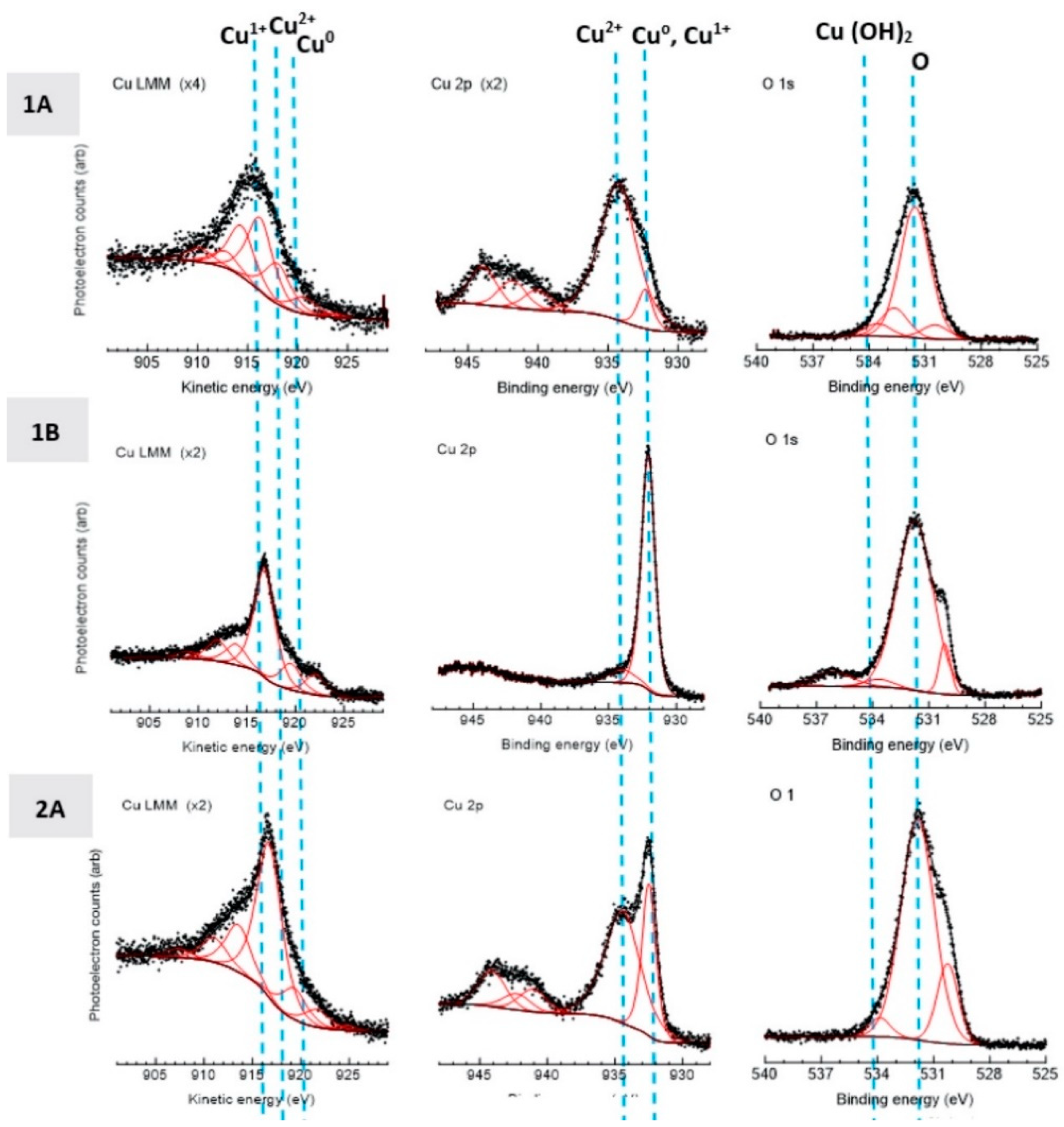
3.4. Electrochemical, Confocal and XPS Analysis

According to the analysis of electrochemical impedance spectra performed by [87], the left-most trend line corresponds to the specimen that is the most prone to corrosion. As for the rightmost trend line, the specimen with the greatest corrosion resistance is identifiable. However, the work by [87] appears to be incorrect in interpreting electrochemical impedance spectra. By way of considering the work of [88], the left-most trendline would be associated with greater impedance and therefore greater insulation from corrosion. As such, the corrosion testing data obtained for electrochemical impedance analysis suggests that the conventional copper cold spray coating is less prone to corrosion, while the nanostructured Cu cold spray coating is less corrosion-resistant than the conventional coating but more resistant than the bulk/wrought Cu sample. The aforementioned electrochemical impedance is illustrated in Figure 25.
The greater corrosion rate of the nanostructured Cu cold spray coating was partly attributable to the roughness of the sample at the finest length scales versus the conventional Cu coating [27]. At the same time, the increased rate of corrosion associated with the nanostructured coating speaks to the coating’s chemical activity and reactivity. This can, therefore, be related to the increased contact killing/inactivation of nanostructured Cu cold sprayed material [23,89] relative to bulk/wrought and conventional Cu cold spray coating since the nanostructured system more readily releases Cu ions.
From the electrochemical impedance spectroscopy of the bulk/wrought, conventional and nanostructured Cu materials, the charge transfer resistance and double-layer capacitance were determined. As resistance decreases, there is an increase in capacitance, where capacitance is directly proportional to the rate of corrosion [90,91]. The conventional coating’s charge transfer resistance and double-layer capacitance were found to be 467.5 ohms and 0.0164 farads, respectively. As for the nanostructured Cu coating, the charge transfer resistance and double-layer capacitance were 382.5 ohms and 0.1057 farads, respectively. Regarding the bulk/wrought Cu, the charge transfer resistance and double-layer capacitance were 325 ohms and 0.124 farads, respectively.
The linear polarization data was found to support the electrochemical impedance spectroscopy findings as well (Figure 26). Additional confirmation of the trends observed through linear polarization and electrochemical impedance spectroscopy was obtained via the ion release assay data as presented in Figure 27. Results demonstrated the fact that the nanostructured Cu coating resulted in a greater concentration of ions in solution versus that of the conventional Cu coating. According to the EPA’s protocol for antimicrobial efficacy, the time of greatest interest is the 2-hour mark. The nanostructured Cu coating demonstrated greater cumulative ion release through the 1-day mark (thus, including the 2-hour EPA benchmark). By way of correlating the relative corrosion rates with the ion release assay findings, the electrochemical testing and ion release study were found to support one another.
SEM micrographs of the perpendicular and parallel orientations relative to the spray direction for the corroded and as-manufactured conditions illustrated little qualitative microstructural differences (Figure 28). However, localized corrosion pitting was readily observable in the nanostructured Cu coating. Cross-sectional analysis of the corrosion tested specimens confirmed the fact that the observed electrochemical phenomena occurred as a surface-scale phenomena since there was little corrosive penetration into the specimens. From electron microscopy alone, little difference was observed between the thermally processed and as-manufactured samples after corrosion as well. The SEM micrographs can be found in [18,25]. The thermal processing was done to collect initial insights upon the effect of heat treatment post-processing of cold spray Cu on the resultant corrosion behavior.
In terms of compositional analysis, the resolution EDS and XRD testing rendered the methods proved to be unable to provide insightful elemental-scale characterization. That being said, XPS analysis of the conventional and nanostructured Cu cold spray coatings was telling in terms of the Cu ion species present and the ions relative concentrations. XPS analysis was presented in Figure 29. From XPS analysis, Cu2+ was found to dominate the photoelectron spectra associated with the conventional Cu coating, whereas Cu1+ was found to dominate the spectra for the nanostructured Cu coating. In relation to the study of the antipathogenic behavior of each of the cold sprayed materials, this observation is extremely significant. A number of researchers studying Cu ion inactivation of pathogens attribute greater contact killing/inactivation efficacy to Cu2+ ions. However, as we have previously shown, the nanostructured Cu coating outperforms the conventional Cu coating and houses a greater concentration of Cu1+, which contradicts some long-standing hypotheses [92], contradicts the forthcoming claim by Champagne et al. that “Cu2+ ions [are] needed for microbial destruction” [23,24,89], and supports our earlier discussion surrounding the role of Cu1+ in inactivating and killing pathogens.

3.5. Relation to Contact Killing Mechanisms

Surface roughness was not the only matter worth continued consideration. Given the overarching materials perspective discussed and presented thus far, attention will be given to prospective linkages between the mechanical, chemical, and microstructural character of the nanostructured and conventional Cu coatings and perspective mechanistic frameworks associated with antipathogenic biological performance. Particular focus will be attributed to surface roughness and texture, dislocation driven ion diffusion, grain boundary mediated diffusion, chemistry, and surface species, among other noteworthy aspects.
As discussed by Vincent et al. [93], “The exact mechanisms involved in the so-called ‘contact killing’ are still not fully understood.” Universally speaking, the antipathogenic contact killing/inactivation ability of Cu has been attributed to the ability to damage DNA [94], cytoplasmic membrane damage [94], particle membrane penetration [95], reactive oxygen species [96], surface roughness and Cu ion species [97], among others. It was outside of the scope of this work to definitively attest to which of the aforementioned mechanisms is the absolute driving force behind the contact killing of pathogens by Cu surfaces. Instead, the results observed, reported, and discussed to date will be placed within the context of the mechanisms described in prior works of scholarship.

3.5.1. On Atomic Cu Ion Diffusion

Whether or not DNA damage, cytoplasmic membrane damage, reactive oxygen species or Cu ion speciation is the dominant pathway attributable to Cu contact killing/inactivation, the microstructural and physical polycrystalline properties reported herein play a role in each. In [89], Champagne et al. attributed the increased killing and inactivation efficacy to the fact that the cold spray process leads to “extreme work hardening and correspondingly high dislocation density within the deposit… [where] Ion diffusion in metals is augmented by the presence of grain dislocations, known as ‘pipe diffusion,’ and ionic diffusion occurs principally through these dislocations… Diffusivity in metals thus varies as the square of hardness and is therefore very sensitive to impact hardening by cold spray deposition. The diffusion of copper ions can therefore be significantly increased through the hardness increase produced by the cold spray process, which serves to enhance the flow of Cu2+ ions needed for microbial destruction.”
In keeping with Champagne et al.’s line of thought, the fact that the nanostructured Cu cold spray coating was found to have a higher hardness (2.37 GPa) than the conventional Cu cold spray coating (2.01 GPa) was consistent with the hypothesis prescribed by [89]. As has been shown in [18,26], the nanostructured Cu outperforms the conventional coating and also has a higher hardness, which would correlate with increased dislocation density from work hardening and subsequently increase ion diffusivity as hypothesized by Champagne et al. However, additional inspection needs to be given to the work-hardened induced increase in dislocation density as the underlying cause of increased antipathogenic performance. In the passage taken from [89], the term “grain dislocations” is utilized.
The use of “grain dislocations” requires semantic consideration since the implication and interpretation from this expression can vary accordingly. Generally speaking, plasticity is discussed in terms of either grain boundaries or dislocations. For example, the Hall–Petch relation is expressed in terms of grains, whereas Taylor’s expression of flow stress is related to the dislocation density of a material. More to the point, the accommodation of plastic deformation by way of crystalline metals postulates that dislocations build up upon grain boundaries, where grain boundaries prevent dislocation transmission until the dislocation accumulation overwhelms the boundary and continues through the grain. As such, one tends to appreciate both dislocations and boundaries between grains as discrete yet interacting systems. If accumulated dislocations along prior grain boundaries are accepted as “grain dislocations,” then the hypothesis that contact killing/inactivation is driven by dislocations stands to be refined to include a composite effect of grain-boundary-mediated ion diffusion and dislocation pipe diffusion. While this is a reasonable interpretation of the use of “grain dislocations,” additional consideration of work [24] following the 2013 article by Champagne et al. seems to suggest that Champagne et al.’s hypothesis is that dislocation cores alone are truly responsible for ion diffusion and thus contact killing/inactivation.
Historically, the ability to tease out the diffusivity attributable to grain boundaries versus dislocations has been limited. Nevertheless, advancements in high-resolution TEM and computational tools have enabled researchers to probe and refine diffusion models based upon defects within a material. Though diffusion along dislocations is nearly always greater than the bulk material diffusion rate, research concerning severely plastically deformed nanostructured materials has demonstrated that diffusion along low-angle grain boundaries is much lower than that of the diffusivity associated with high angle-grain boundaries [98]. Since low-angle grain boundaries are historically treated as arrays of dislocations [99], it stands to reason that grain boundary mediated diffusion can outperform dislocation-driven pipe diffusion in severely plastically deformed nanostructured material. This is due to the fact that high-angle grain boundaries were found to yield a greater degree of diffusivity versus low-angle grain boundaries by [98], thus suggesting that grain boundaries that are not composed of structured dislocations will more readily diffuse ions.
That being said, there is also evidence of a compounding effect upon the rate of diffusion associated with planer defects, i.e., grain boundaries in a nanostructured metallic system, if dislocation defects are interior to the grain boundary, as demonstrated by [100]. This enhanced diffusion brought about by non-equilibrium and greatly defected boundaries in nanostructured materials is known to follow from severe plastic deformation processing. Given the work-hardening and strain-rates associated with cold spray deposition, it is likely that enhanced Cu diffusion capacity of the nanostructured coatings was not only a result of the highly disoriented boundaries between grains but also because of internal defects within the boundaries themselves. As such, this proposed compounding effect builds upon the dislocation-driven diffusivity hypothesis proposed by Champagne et al. by beginning to differentiate between low-angle grain boundaries, high-angle grain boundaries, accumulated dislocations, non-grain boundary dislocations, interior grain boundary dislocations, and exterior grain boundary dislocations.
Future work will require a mechanistic and detailed study of the exact contributions from the aforementioned crystalline defects to the diffusion of Cu ions from antipathogenic Cu cold sprayed surfaces. Just as previous work has established the fact that different classes of grain boundaries experience varied diffusivity as a function of their disorientation angle and low- (e.g., tilt or twist) or high-angled structure, dislocation-based defects also vary in terms of their respective rates of diffusion. Specifically, chemical diffusion was studied in-silico to understand the effect of “screw dislocations, edge dislocations, and polycrystal boundary” defects upon diffusion [101]. The enhancement of the mean-square displacements of diffused atoms in screw dislocations was shown to be an order of magnitude lower than that of edge dislocations, thus speaking to the specific dislocation-dependent nature of diffusion. Needless to say, both screw and edge dislocations succeed in enhancing diffusion, albeit to varying degrees.
Recent research has been published in support of dislocation-driven and line-defect-dominated Cu ion diffusion as the microstructural constituent responsible for pathogen contact killing/inactivation [102]. However, their work did not explicitly consider the grain size as a prospective driving force for ion diffusion, which would have attested to the area-fraction-containing grain boundaries, in relation to increased antipathogenic activity. Instead, they use XRD-derived dislocation density as the structural property responsible for increased ion diffusion, even though the crystallite size was also shown to decrease concomitantly with the increase in dislocation density; though the grain size would not be attainable from the crystallite size for the cold-rolled Cu studied in [101] since the grain size is unlikely to be nanostructured and therefore too coarse for XRD-based determination.
Research concerning the antipathogenic nature and corrosion resistance of a conventional Cu cold spray coating was also studied and reported upon in [103]. Regardless of the fact that the authors consider adiabatic shear instability as the main mechanism associated with metal–metal bonding during cold spray particle deposition without consideration of the alternative shock-wave mechanism [8], and evidence demonstrating the timescales associated with the onset of adiabatic shear instabilities [104], their observation that “particle softening overcomes its work hardening,” in part, during consolidation, was particularly astute for the purpose of analyzing this work [103].
In other words, [103] observed longstanding phenomena of Cu softening during cold spray processing from a complete work-hardened state. If this observation is coupled with the previously noted dynamically recrystallized grains, then the immediate accumulation of dislocation density upon impact will be slightly reduced as subsequent particles are deposited [20]. This is due to the fact that the dynamically recrystallized grains follow from the accumulation of dislocations induced by particle impact upon prior grain boundaries until sub-grains are formed to accommodate the severe plastic deformation. Thereafter, as the dynamic recrystallization process continues, the sub-grains subdivide further until high-angle grain boundaries, with a significant degree of misorientation between grains, are formed.
Evidence of this process can also be seen in Figure 21, where dislocation accumulation was unable to result in subgrain formation at the prior grain boundary in the upper-left STEM micrograph. At the same time, the bottom-right micrograph in Figure 21 highlights a recrystallized structure where misoriented nanostructured equiaxed grains can be identified. Considering the annihilation of dislocations during the process of multiparticle impact, work by [67] can be considered. From the computational analysis in [67], the single-particle impact achieves a dislocation density of 10 17   m 2 . Experimentally, the subsequent accumulation of particle/particle impacts, and realistic timescale resulted in a dislocation density of 4.78 × 10 14   m 2 , which speaks to partial dislocation annihilation as dynamic recrystallization occurs.
As already mentioned, future work will establish a mechanistic framework for precisely evaluating the specific contributions from the crystalline defects to the atomic diffusion of copper from antipathogenic copper cold sprayed surfaces. In the meantime, approximations surrounding the contribution from grain boundaries and dislocation cores to atomic diffusivity are presented herein to lay the groundwork for forthcoming research devoted to this topic. According to work reported by de Orio, the effective diffusivity ( D e f f ) can be expressed as follows,
D e f f = D l + f g b D g b + f i D i + f c D c ,
where D l is the diffusion coefficient associated with atomic diffusion through the lattice, D g b is the diffusion coefficient for atomic diffusion through the grain boundaries, D i is the diffusion coefficient for atomic diffusion through additional interfaces within a material and D c is the diffusion coefficient for atomic diffusion through dislocation cores, also known as “pipe diffusion” [105]. At the same time, f g b is the fraction of atoms undergoing atomic diffusion via the grain boundary pathways, f i is the fraction of atoms undergoing atomic diffusion via the additional interfacial pathways within a material and f c is the fraction of atoms undergoing atomic diffusion via pipe diffusion [105].
For the purpose of comparing the rank or weight of each contribution to the overall D e f f , one may assume D l = 0 and D i = 0 . Moreover, D e f f may be written as follows by way of substituting the mathematical relations associated with f g b and f c , as well as D l = 0 and D i = 0 , such that
D e f f = δ g b w d w d D g b + ρ a D c ,
where δ g b is the grain boundary thickness, d is the average grain or sub-grain size, ρ is the dislocation density, w is the line width and a is the cross-sectional area of the dislocation cores associated with pipe diffusion [105]. By way of utilizing the D g b and D d reported in earlier work for Cu at similar temperature ranges, one achieves
D e f f = δ g b w d w d 5.09 10 7   m 2   s 1 + ρ a 1.03 10 8   m 2   s 1 .
Considering Tabor’s relation between hardness ( H ) and the yield strength of a material ( σ y ), as well as the Taylor relation between the shear strength ( τ ) and σ y , it follows that
H = 3 σ y = 3 3 τ = 3 3 α μ b ρ ,
where α is a constant equal to 0.5, b is the Burgers vector of Cu with a value of 3.6147 10 10 m and μ is the shear modulus of copper at 45 GPa. Thus, we may solve for the dislocation density associated with the nanostructured coating using the hardness reported in [24,89] for the same nanostructured cold spray coating, such that
ρ = 3.33 10 15   m 2 .
Similarly, we may solve for the grain boundary size of the nanostructured Cu coating using the Hall–Petch relation [84,85,86,106], where
σ y = 25   MPa + 0.12   MPa   m 1 / 2 1 d = H 3
and, therefore,
d = 2.3190 10 8   m .
From the work of Choi et al. [107], we can relate the grain boundary size to the line width such that w 32 nm. Recall that the grain boundary width is equal to 5–10 atoms, yielding δ g b = 1.1 10 9 m. Consequently,
δ g b w d w d D g b = 6.647 10 9   m 2   s 1 .
Next, we can calculate the contribution from the dislocation density, when the cross-sectional area of the dislocation core is calculated from the geometric expression of a pipe, a = π r d 2 , where r d = 5 b , such that
ρ a D d = 3.5198 10 10   m 2   s 1 .
Thus, we see that the grain boundary contribution to the effective diffusivity of Cu ions in the nanostructured material outperforms the diffusivity of dislocation pipe diffusion by an order of magnitude,
6.647 10 9   m 2   s 1 > 3.5198 10 10   m 2   s 1 .
Having pursued the quantification and rank of the contribution from grain-boundary-mediated atomic diffusion and from dislocation pipe diffusion, in terms of their magnitude and respective contributions to the effective diffusivity of the nanostructured coating, additional discussion, which strives to substantiate the approach, was warranted and ought to be offered to the reader.
Regarding hardness, L. Tuckerman said it best when he stated that hardness is “a hazily conceived conglomeration or aggregate of properties of a material, more or less related to each other,” [108]. In other words, hardness is not an innate material property and does not provide us with fundamental insights into a material’s behavior under tensile and compressive stresses and strains. That being said, nanoindentation researchers have continued to improve upon the range of properties that can be measured. As such, spherical indentation stress–strain curve evaluation has become a reality and continues to improve in terms of serving as a reliable alternative to traditional tensile testing.
In so far as the theory associated with the evaluation of indentation stress–strain curves are concerned, the following definitions associated with a refined protocol are given below.
E * = π 2 S A c
where E * is the reduced modulus, S is the stiffness and A c is the contact area. In so far as A c is concerned, for some reason, contemporary researchers have not recognized the statement by Oliver and Pharr in [40,41], which states that “The contact area and hardness determined by the… [Oliver-Pharr] methods will thus be the same as will be the elastic modulus because… [the Oliver-Pharr method] applies to any indenter geometry.”
Representative indentation strain ( ϵ i ) has been defined as either
ϵ i = 4 h 3 π a c
or
ϵ i = 0.2 a c R e f f
depending upon the researcher, where h is the displacement, a c is the radius of contact and R e f f is the effective radius. In so far as a representative indentation stress is concerned, Leitner et al. [26,42] reestablished the link between mean contact pressure ( p m ) and stress, which was originally established by Tabor, by way of taking a more sophisticated approach to the definition of a constraint factor ( C * ).
Therefore, if
σ r = p m C *
then C * is expressed as a function of the ratio ( μ ) of contact stiffness (S) to the slope of the load/contact depth curve ( n L ), such that
C * μ = 1 , μ = 0.5 2.12 ln μ + 0.5 1.25 + 1 , 0.5 < μ < 1.45 0.55 ln μ + 2.08 , 1.45 μ < 4.5 2.91 , μ 4.5
and
μ = S n L
where
n L = d P d h c
and
h c = 1 2 h .
As a result, the σ y given in Figure 30 substantiates the use of the Hall-Petch relation herein to determine the grain size for use in the aforementioned diffusivity calculations.

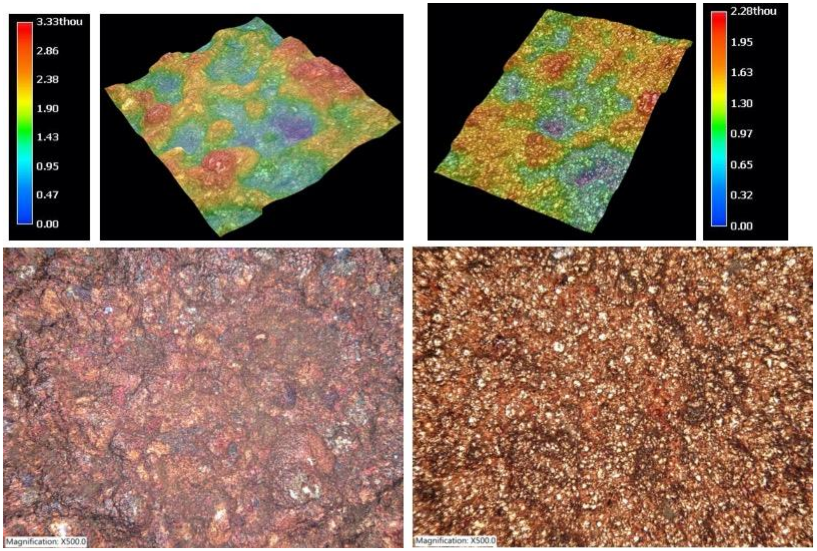
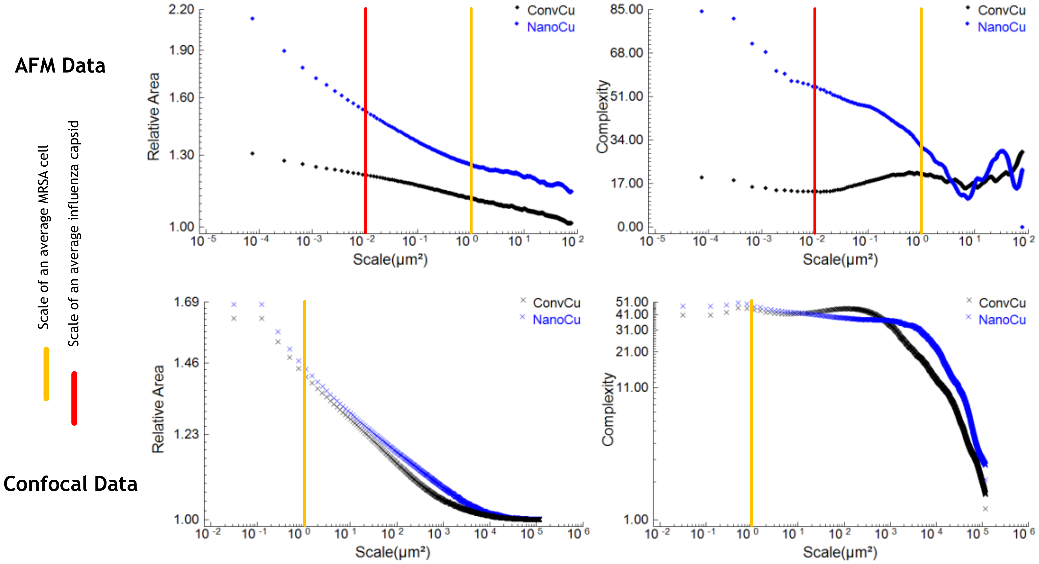
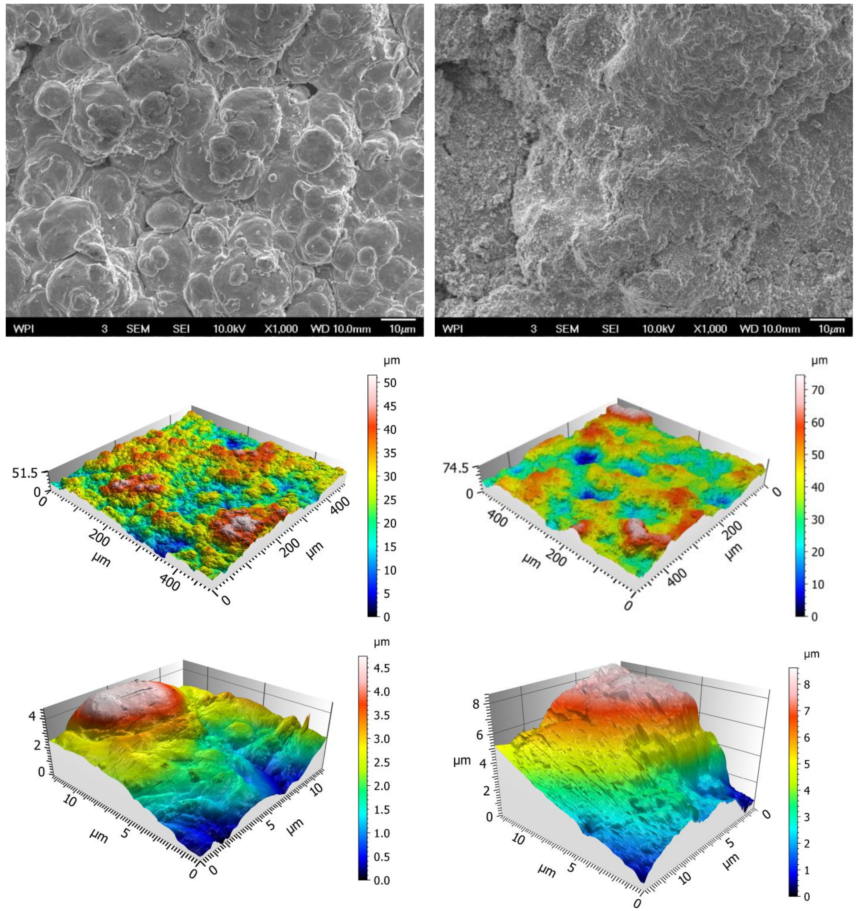
3.5.2. Surface Metrology and Roughness

Much of the discussion thus far has served to relate the properties of conventional and nanostructured Cu cold sprayed materials to their antipathogenic performance as a function of microstructurally mediated ion diffusion mechanisms. However, the importance of surface topography and roughness cannot be overstated. Prior work has aimed towards addressing the role of roughness-driven contact killing and viral inactivation by way of utilizing atomic force microscopy (AFM) and confocal microscopy to identify length-scale dependent topographies in relation to the size of methicillin-resistant Staphylococcus aureus (MRSA) cells and Influenza capsids [18,27]. To that effect, Figure 31 and Figure 32 demonstrate the relative surface areas, surface complexities, and topographies. The topmost left and right SEM micrographs presented in Figure 32 are shown to be consistent with the surfaces observed in the same orientation that was micro-graphed using SEM analysis and presented in Figure 14. At the same time, the renderings of the surfaces presented in Figure 32 also agree rather well with Figure 28 respectively.
Recent work by Selvanmani et al. demonstrated the effectiveness of laser surface texturing of Cu to enhance the bactericidal behavior of Cu surfaces through the modification surface roughness. The direct goal of their work was to create a surface geometry that would kill bacteria via the destabilization and rupture of the cell membranes [109]. Their work is unable, at the moment, to address viral pathogens. As shown in Figure 31 through the use of AFM data, the surface roughness of the nanostructured Cu cold sprayed coating was of a similar order of length-scale to an Influenza capsid with greater relative area and complexity than the conventional Cu cold sprayed coating. Finally, good agreement between Figure 32 and Figure 28 was shown by way of confocal analysis using two different systems (one from Keyence, Figure 28, and one from Olympus, Figure 32).

3.6. On Copper and Covid-19

In a recent correspondence to the editor of The New England Journal of Medicine, researchers demonstrated the contact inactivation efficacy associated with Cu in relation to SARS-CoV-2, the novel human coronavirus responsible for the ongoing Covid-19 pandemic [110]. Specifically, they revealed the fact that SARS-CoV-2 was no longer viable after exposure to Cu for 4 hours when a 99.9% pure bulk/wrought Cu sheet was used as the Cu surface. The EPA has previously recognized and qualified a range of Cu-based materials as being antipathogenic and classifiable as a contact killing/inactivation surface as long as they contain at least 60% Cu. That being said, the alloying chemistry, Cu manufacturing method utilized, and materials processing raise or lower the respective pathogenic kill and inactivation rates. Because different Cu coating manufacturing systems achieve various rates of disinfection, as has previously been shown when plasma sprayed, wire sprayed, and cold sprayed Cu surfaces were compared with one another [24,89], the deposition technology must be optimized with respect to maximal inactivation rate in the fight against and management of Covid-19.
Prior work has showcased the noteworthy antipathogenic properties of Cu cold sprayed surfaces against Influenza A, MRSA, Staphylococcus aureus and Pseudomonas aeruginosa. Given the successful inactivation of more than 98% of the Influenza A virus after 2 hours of exposure to said Cu cold sprayed surfaces, it stands to reason that the enhanced understanding of the material properties underpinning the antipathogenic performance of Cu cold sprayed material consolidations described herein can be built upon for quick optimization and deployment in hospital/medical environments as a targeted mitigation strategy in response the current Covid-19 pandemic. In fact, the materials science community has also started to advocate for the antipathogenic functionalization of common touch surfaces in public areas through the use of Cu in the fight against Covid-19 too [111]. Regarding cold spray, VRC Metal Systems, a manufacturer of cold spray equipment and systems, has also recognized the potential for Cu cold spray as preventative technology in response to Covid-19, as highlighted by a blog post released on 27 March 2020.

4. Concluding Remarks

During the course of this work, microstructural analysis was performed upon GA Cu powder, spray-dried Cu powder, single-particle deposits of each powder upon an Al substrate, and the resultant cold spray Cu coatings manufactured via both feedstock materials. Additional analysis of the impact behavior and impact velocities required for particle/substrate bonding was studied via advanced LIPIT experimentation. Mechanical properties were also assessed for each of the coatings in an orientation that most closely resembles the coatings surface that would function as an antipathogenic contact killing/inactivation material. As showcased in the Results and Discussion section, the aim of addressing the knowledge gap surrounding the microstructural variations between these two types of cold sprayed materials was achieved in large part. Thus, particular observations and findings are itemized hereafter.
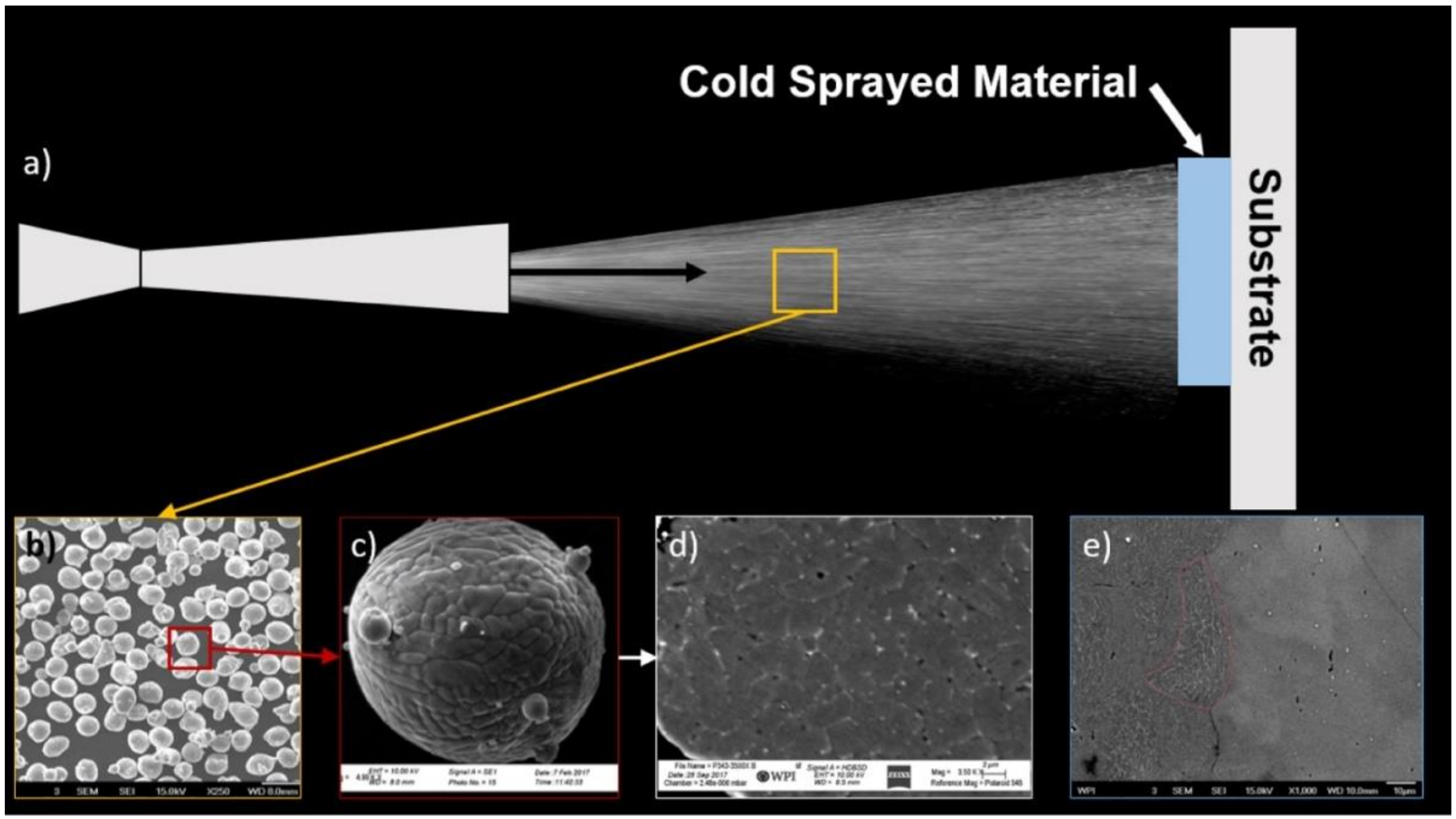
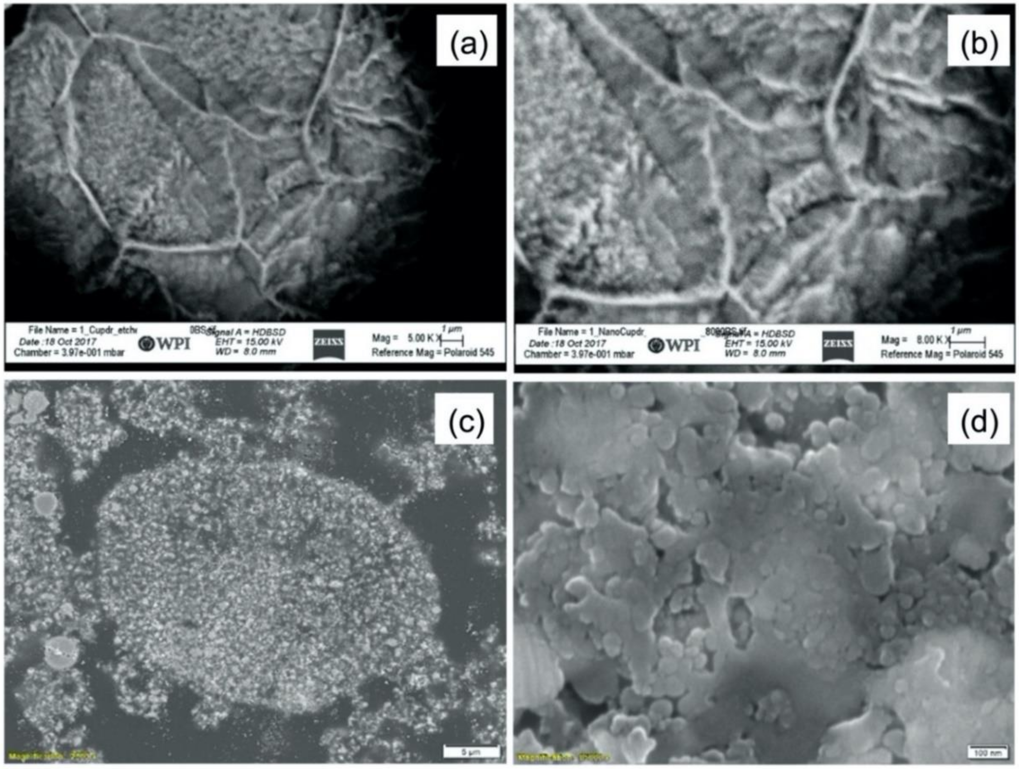
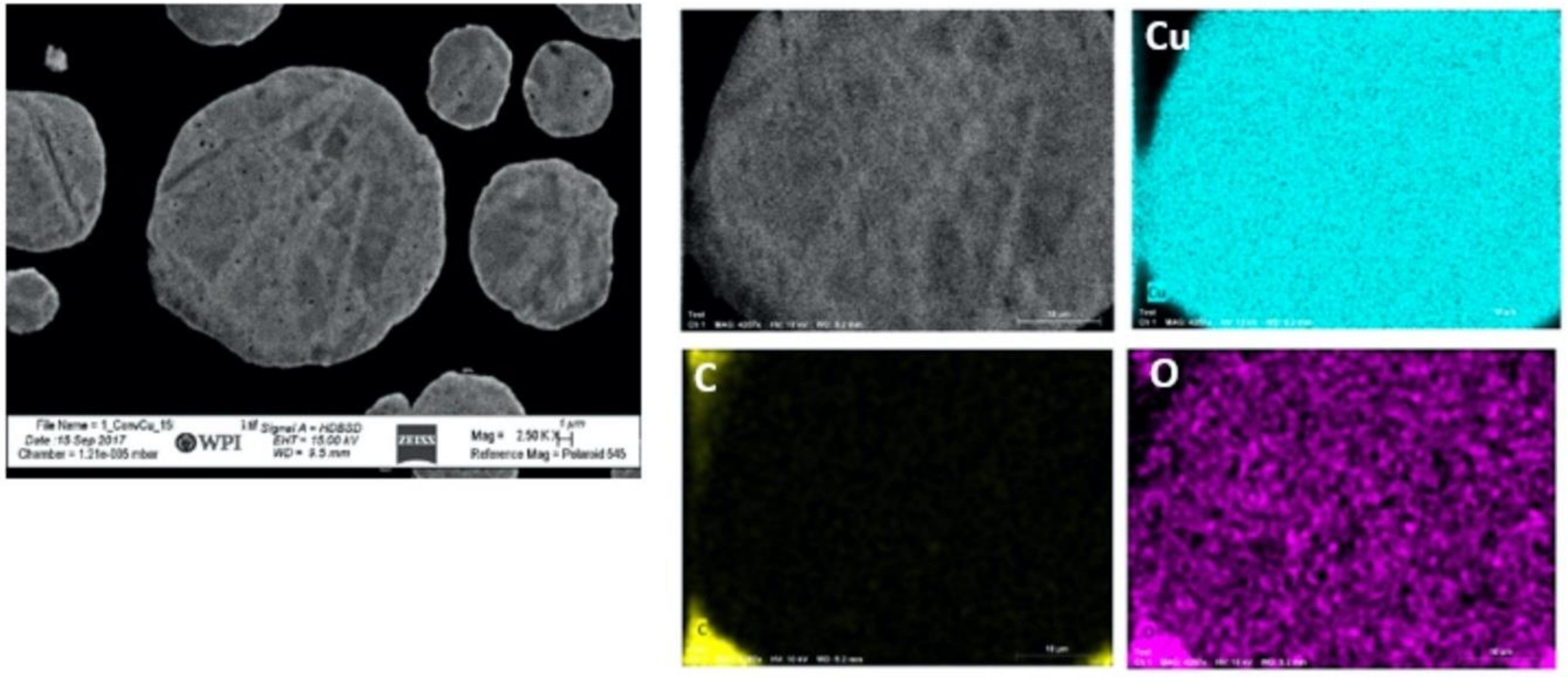
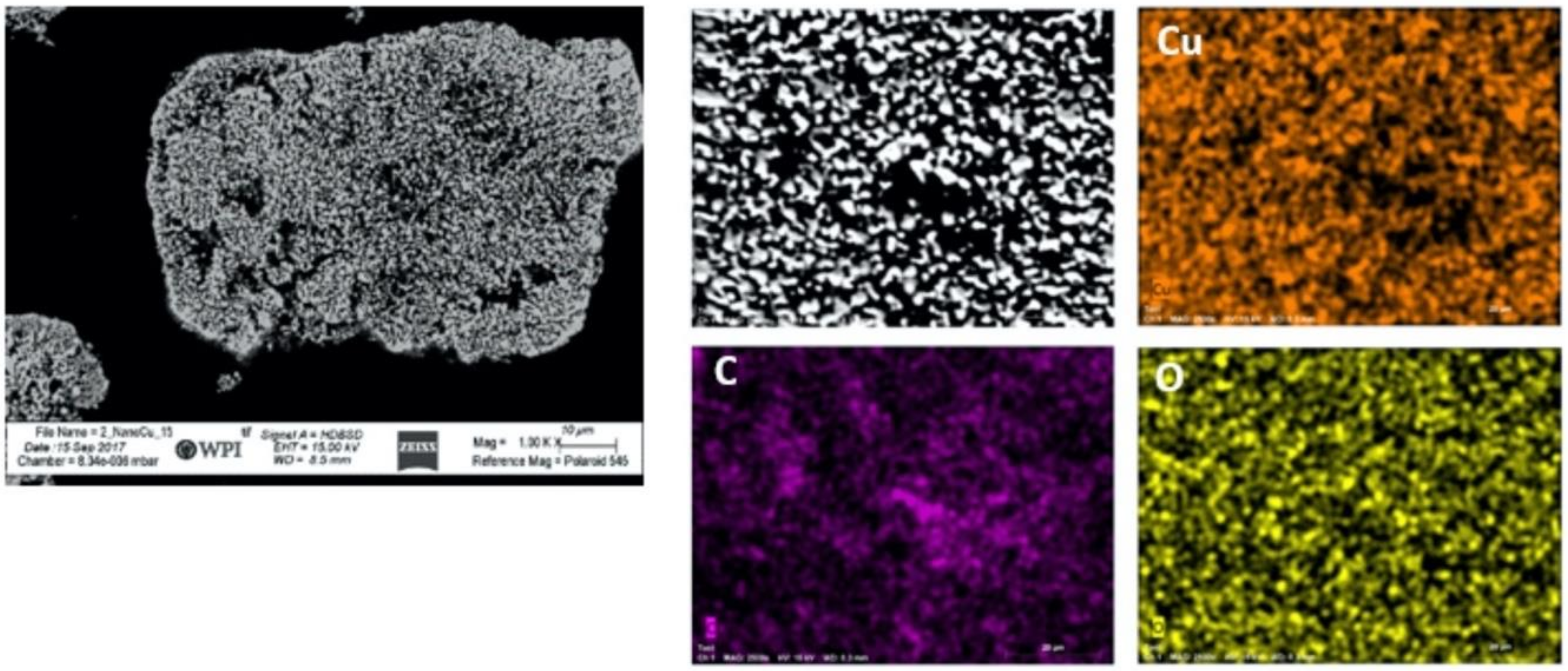
  • The spray-dried Cu powder was shown to have finer grains and greater porosity than that of the GA Cu powder. The limited porosity of the GA Cu powder is attributable to trapped gas during solidification. The 50% porosity measured for the spray-dried Cu powder is directly attributable to the spray-drying manufacturing process itself. The measured microstructural feature sizes of the GA Cu powder were shown to agree well with theoretical predictions of the SDAS as a function of particle diameter and therefore particle cooling rate during the rapid solidification experienced in association with the GA process.
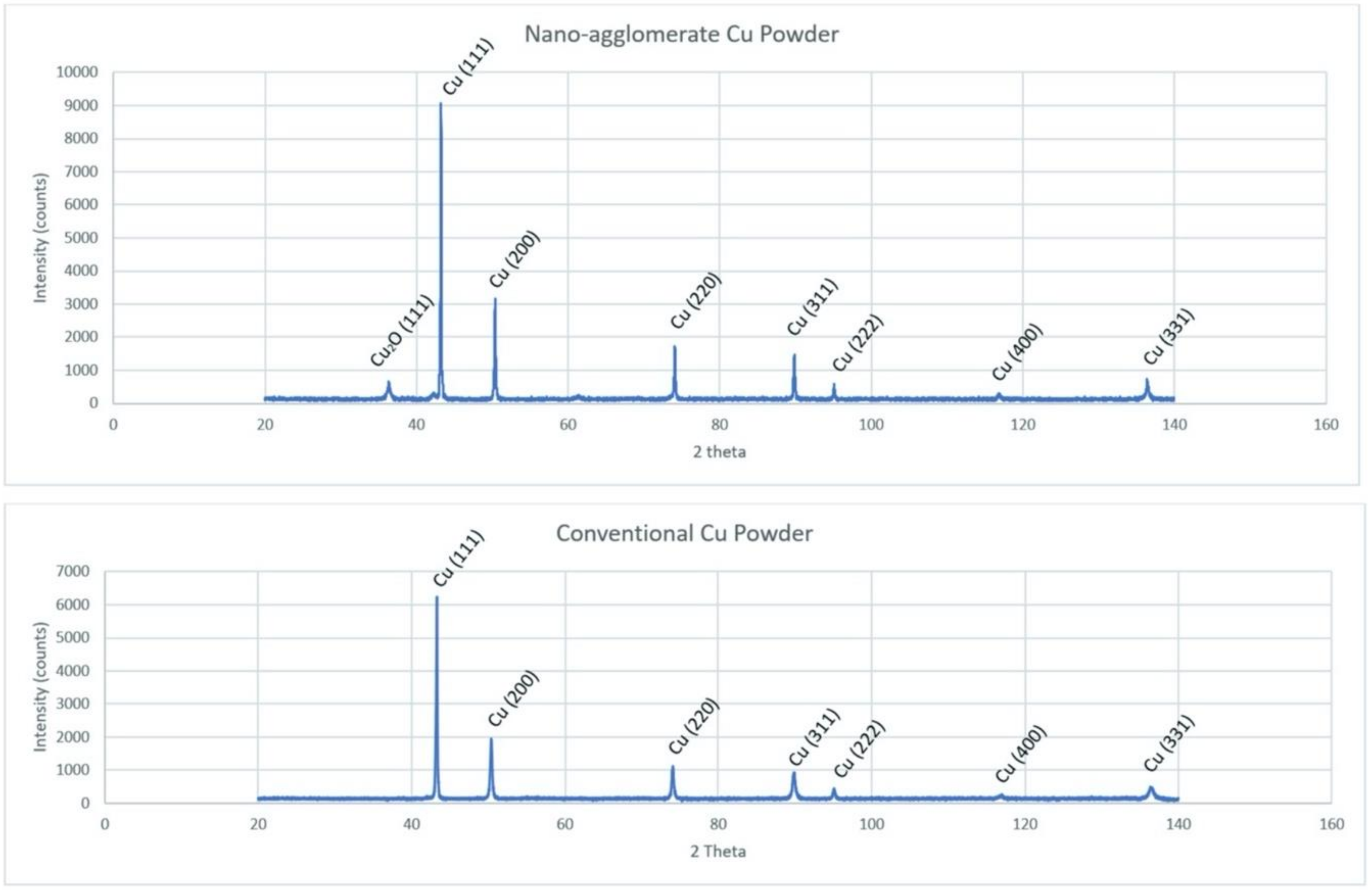
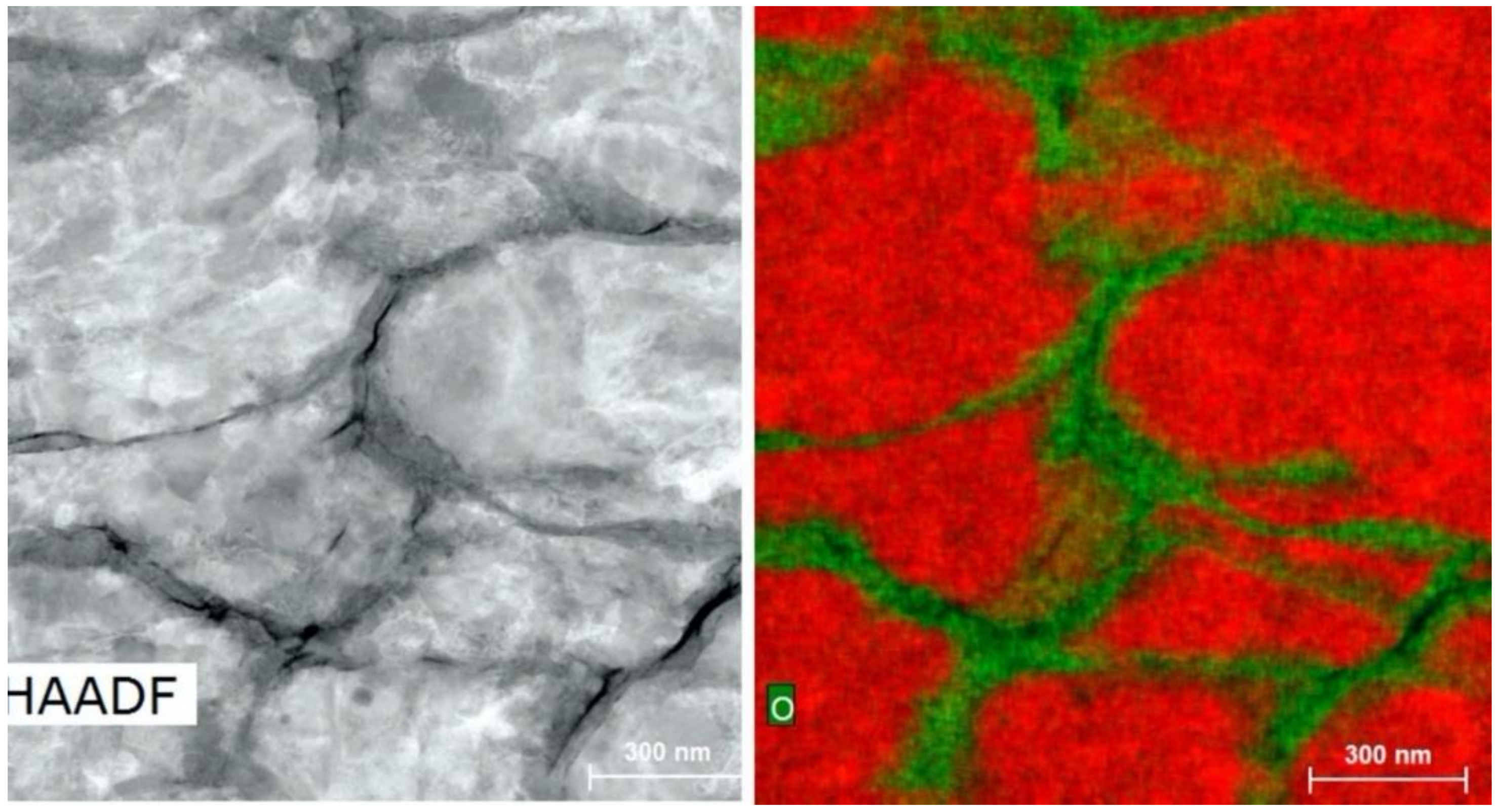
  • PXRD revealed that Cu2O was present in the spray-dried Cu powder but not the GA Cu powder. EDS was performed in conjunction with PXRD. Future work should explore this difference between the two powders and the influence of the Cu2O oxide species upon the deposition of spray-dried Cu during cold spray processing. Prior work that utilized XPS had been reported regarding the surface species and composition for each of the coatings [24]. Future work could attempt to build upon the role of this Cu-oxide species upon contact killing/inactivation mechanisms and efficacy.
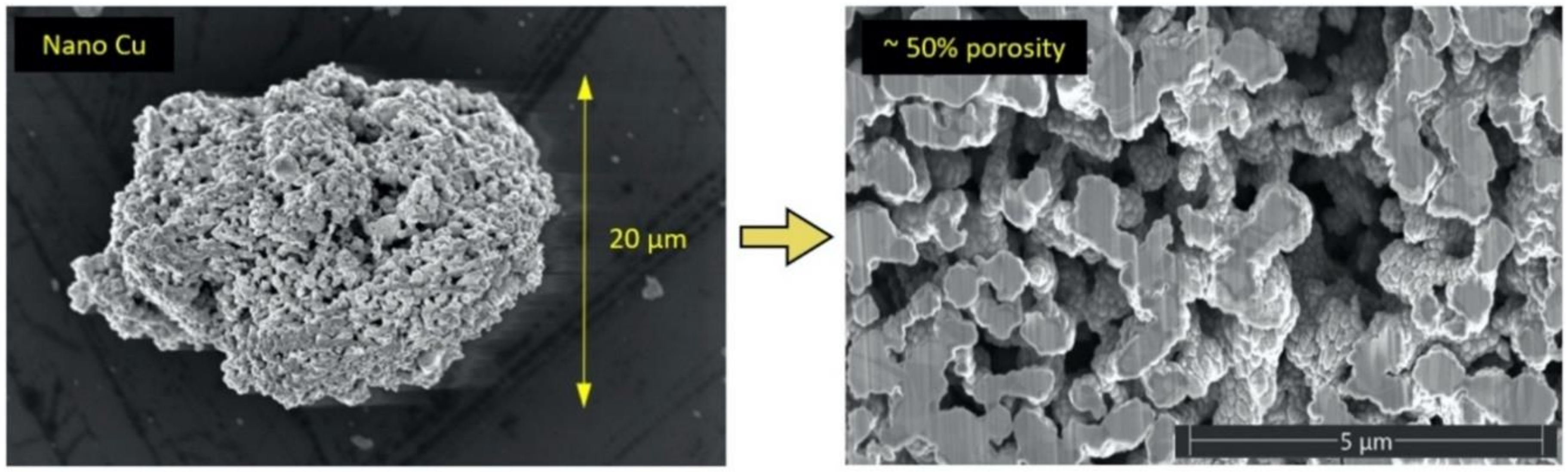
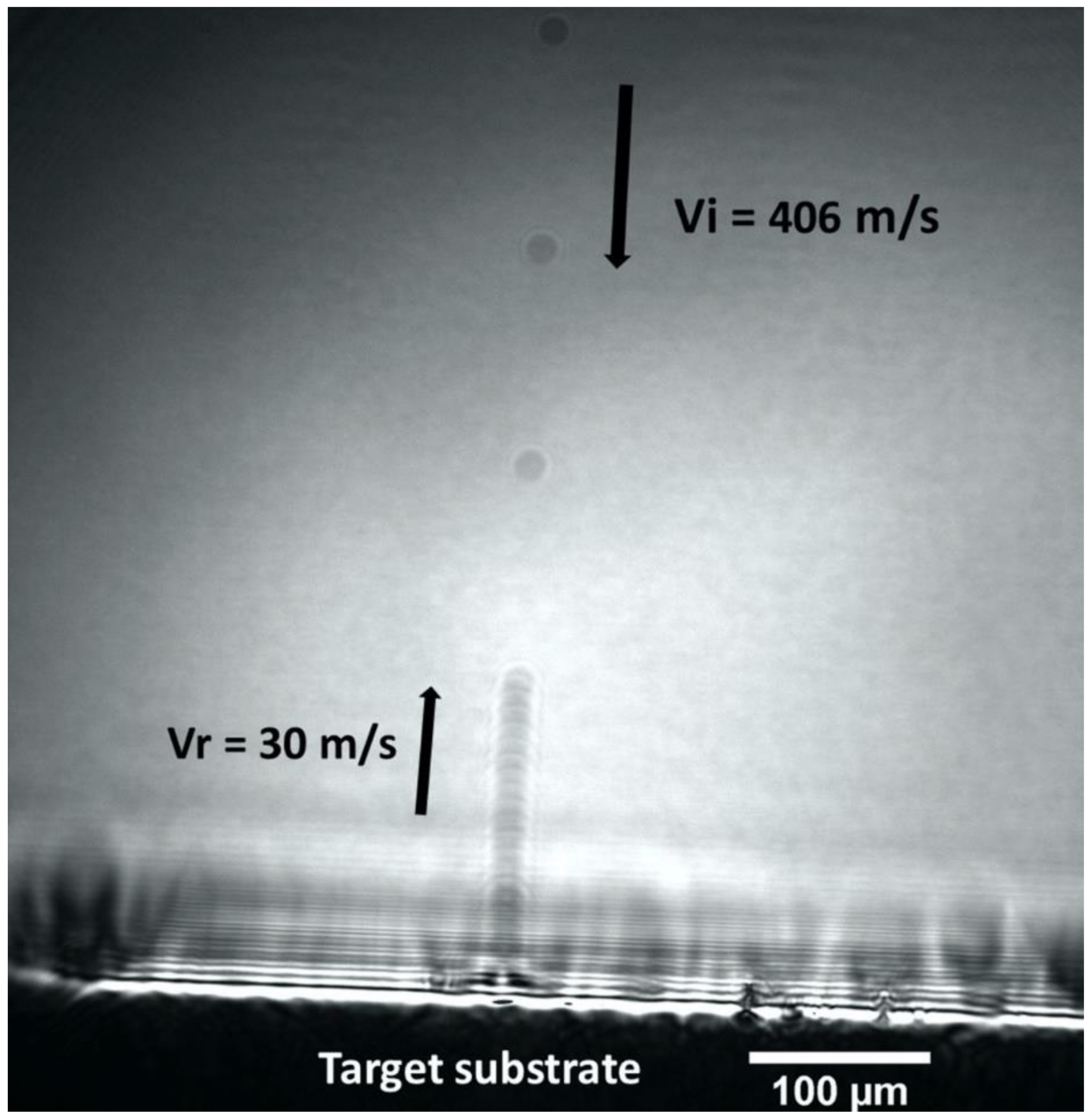
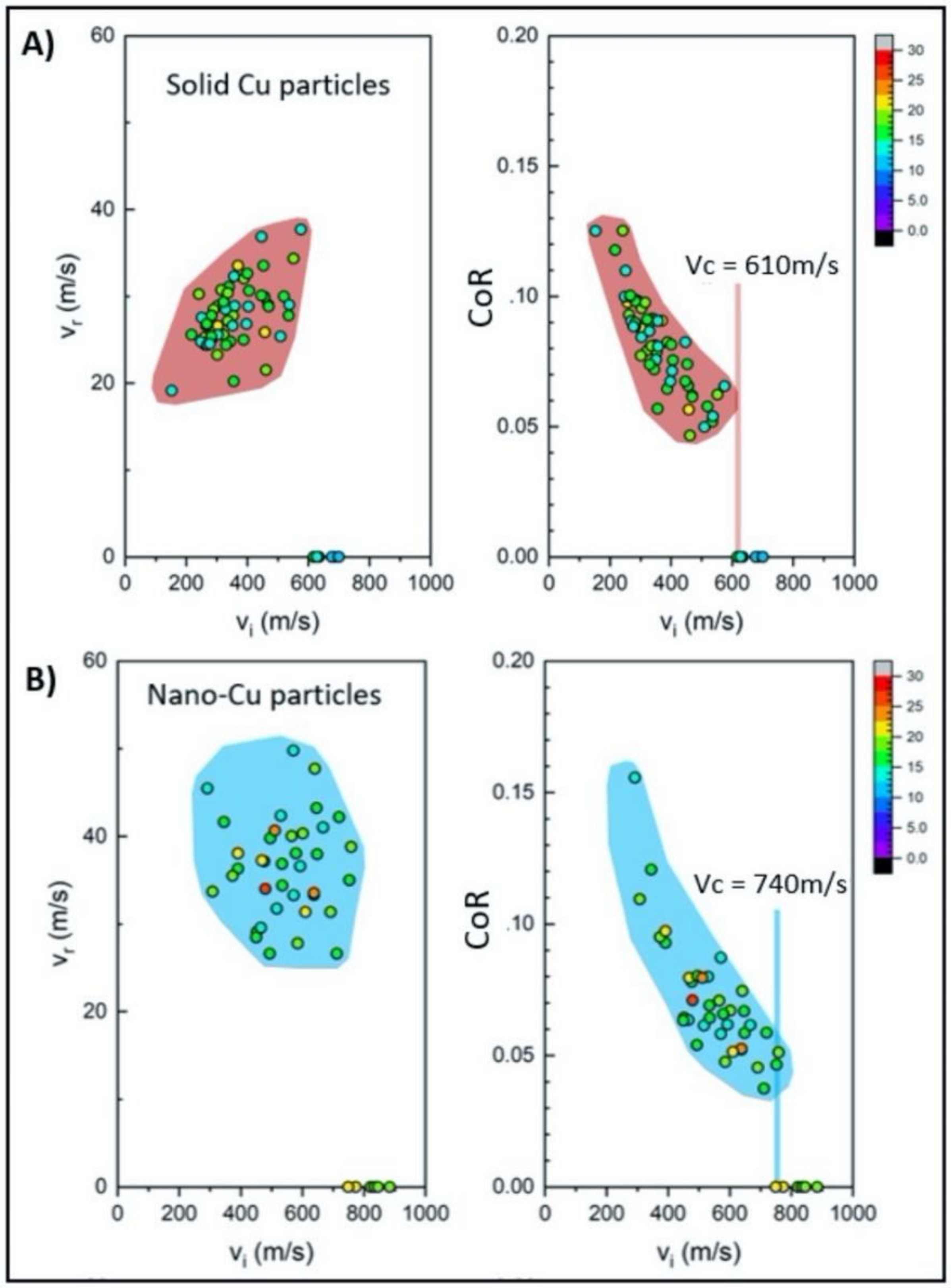
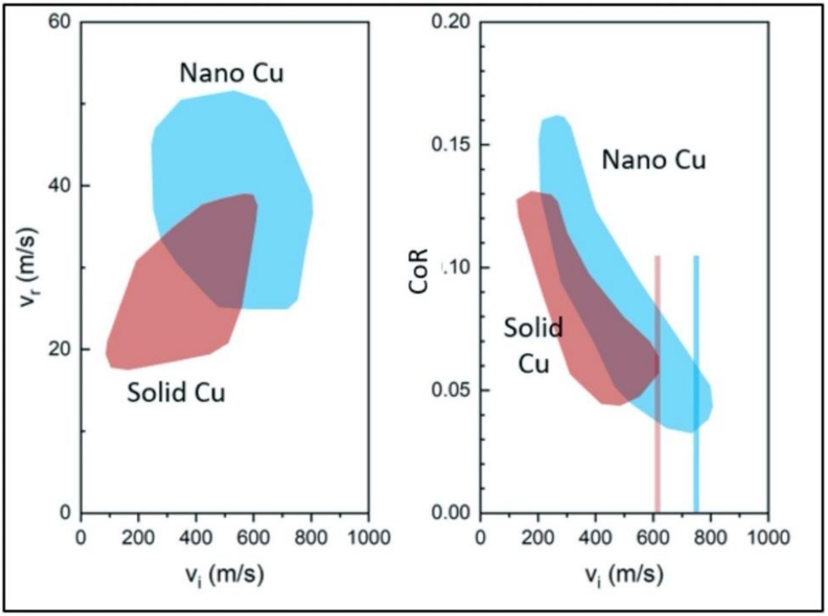
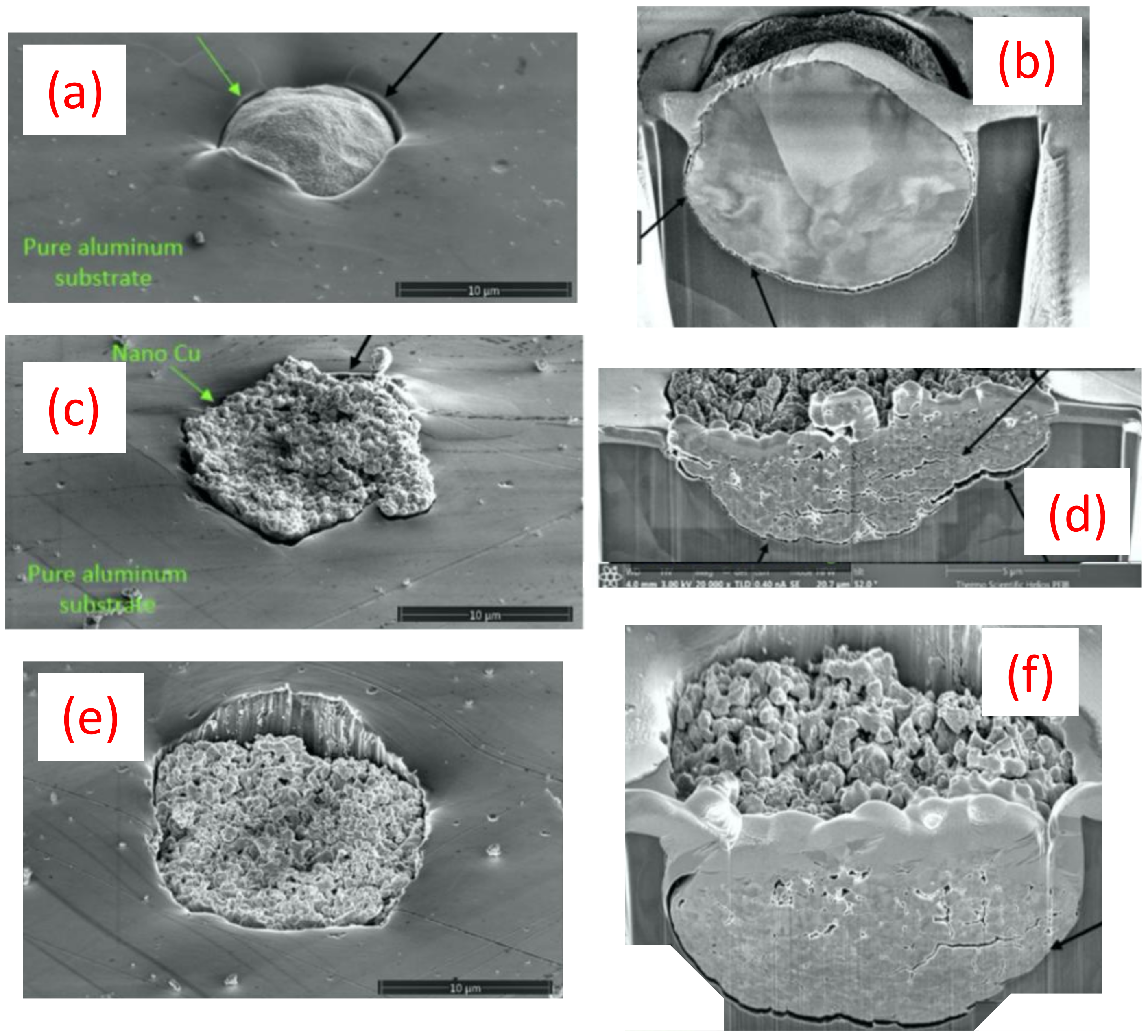
  • The advanced LIPIT testing identified a critical impact velocity of 610 m/s for the GA Cu particles with a 15–20 μm diameter. As for the spray-dried Cu powder, particles with a diameter of 15–20 μm were found to have a critical impact velocity of 740 m/s. Although prior research has demonstrated increases in the degree of deformation experienced by conventionally manufactured Cu feedstock and impact velocity, a clear trend in densification as a function of impact velocity for the nanostructured powder was determined during the course of this work. Spray-dried Cu powder porosity was found to be 50% and was shown to reduce to 10% upon impact. Cross-sectional micrographs of single particles of spray-dried Cu powder deposited using LIPIT unveiled a porosity gradient where the region of the impacted powder closest to the substrate had the lowest retained porosity.
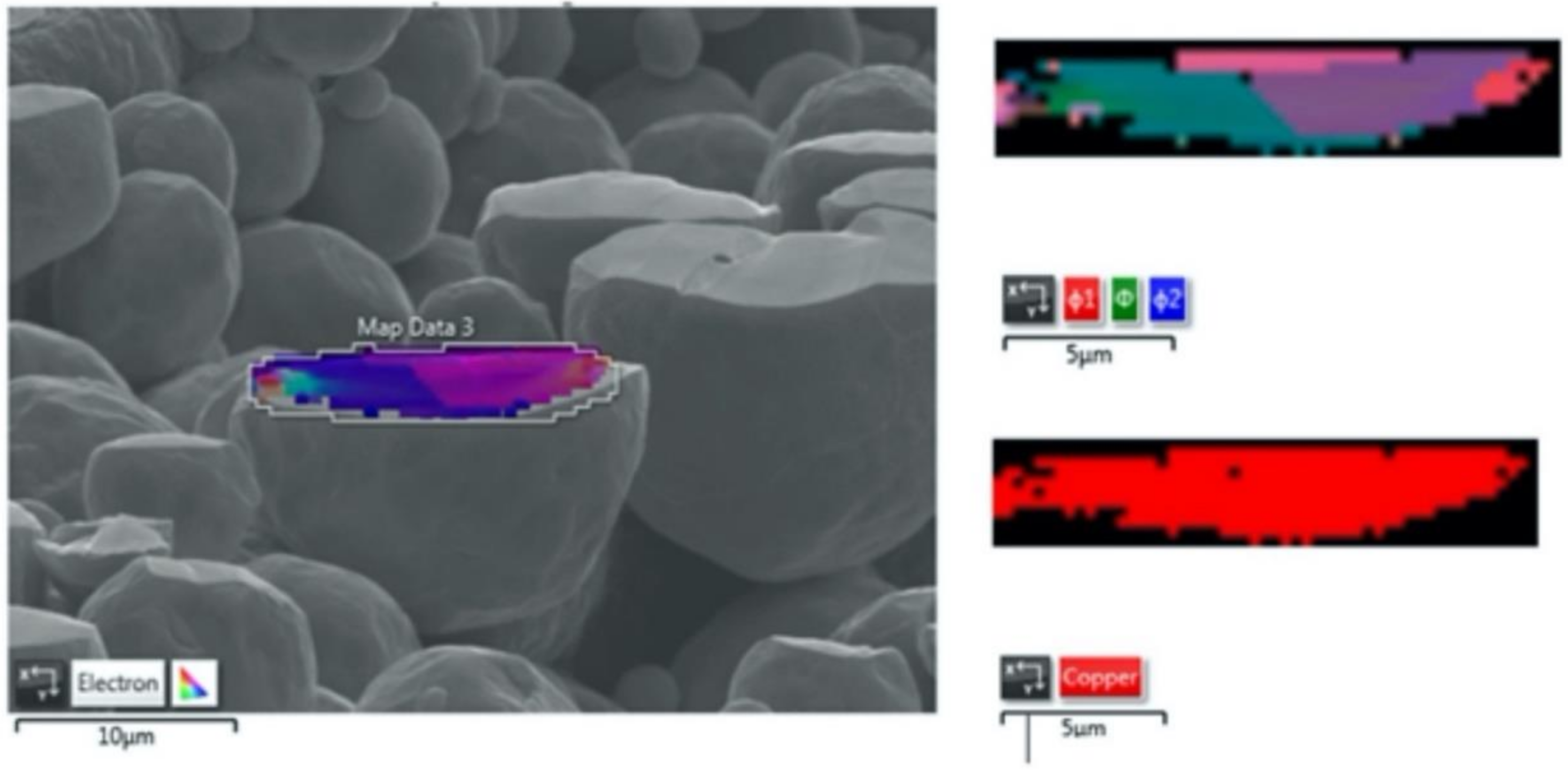
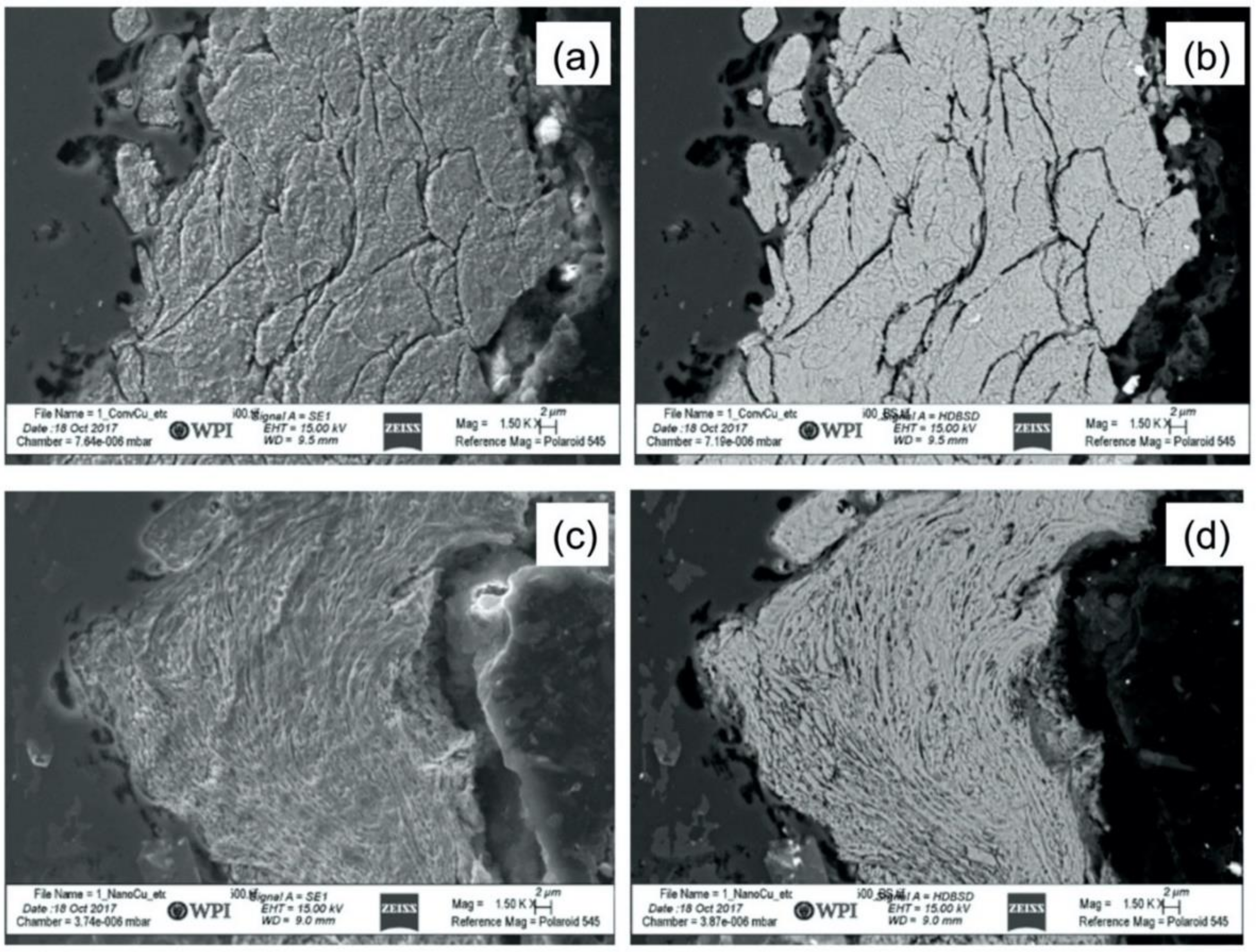
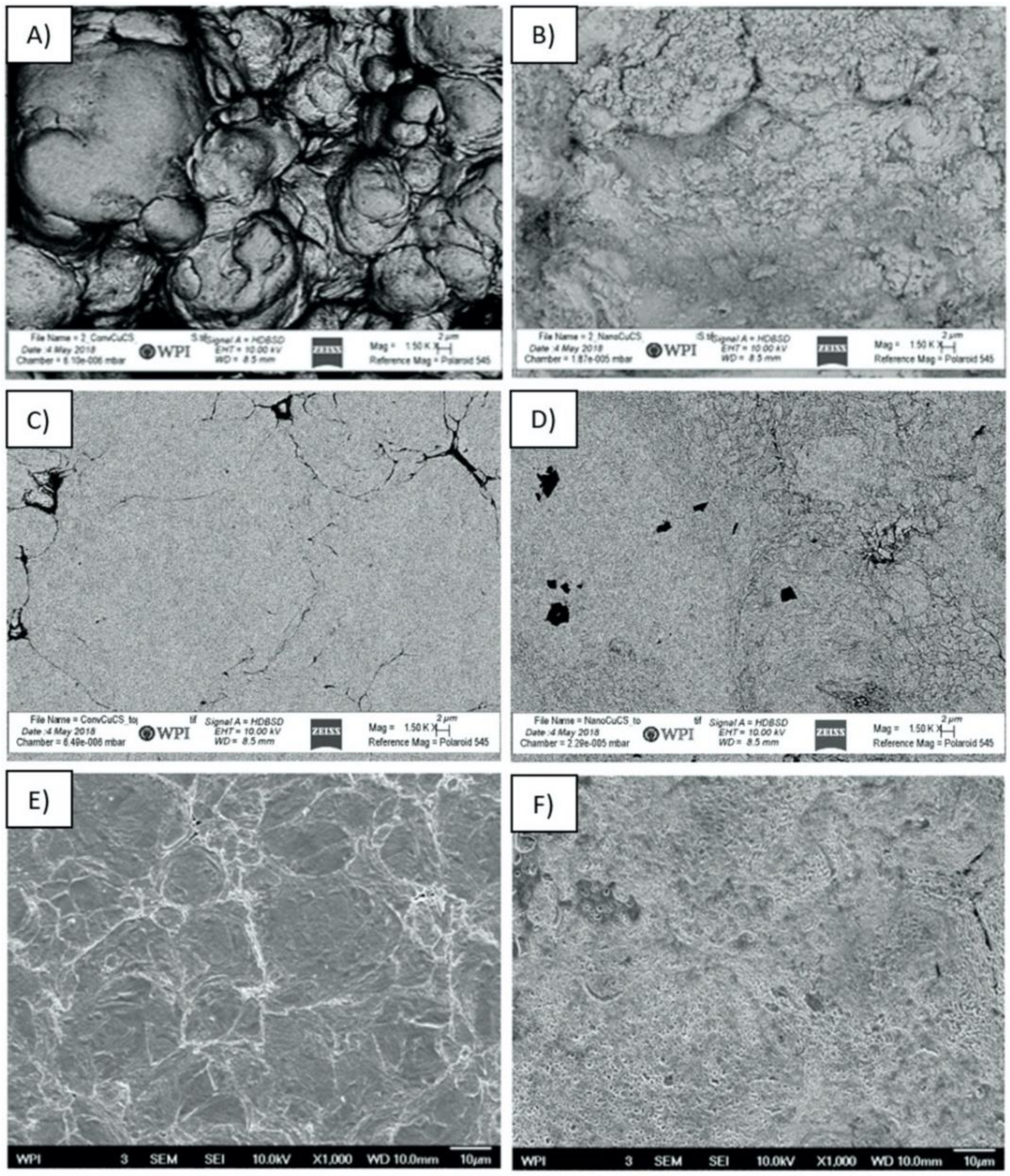
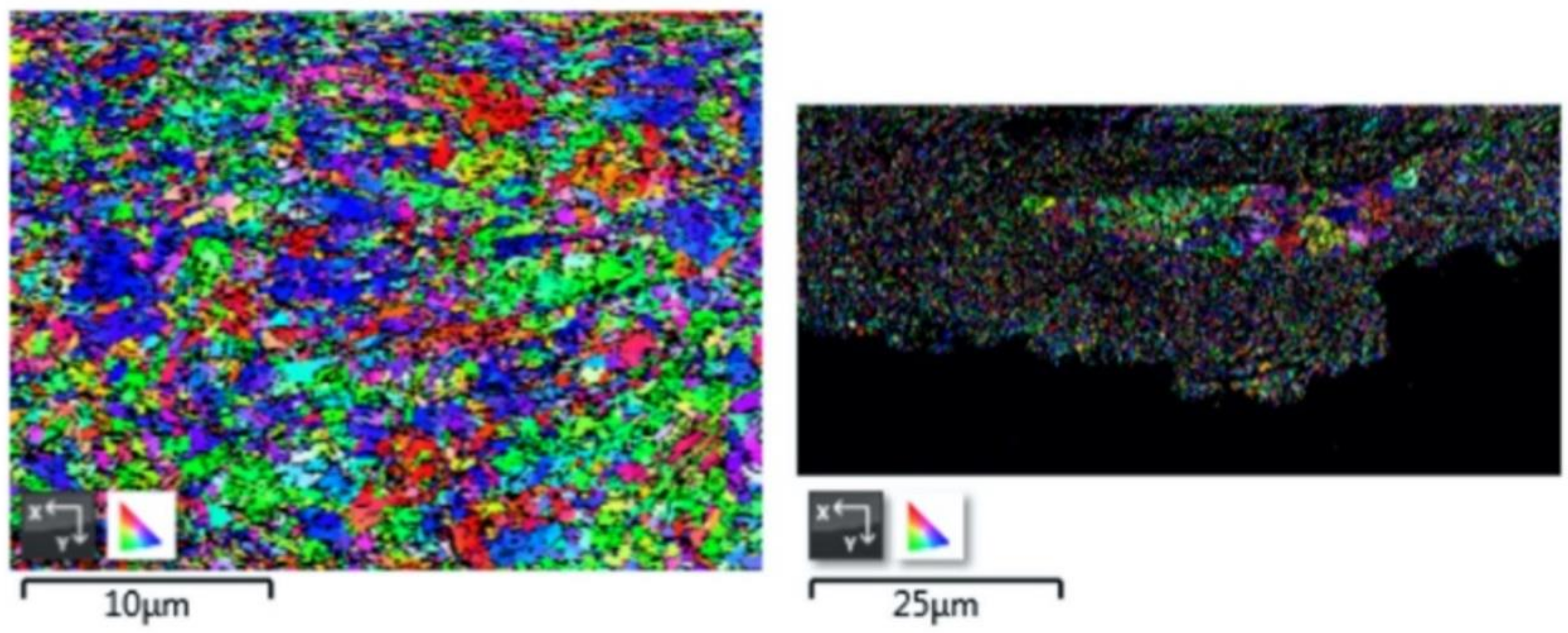
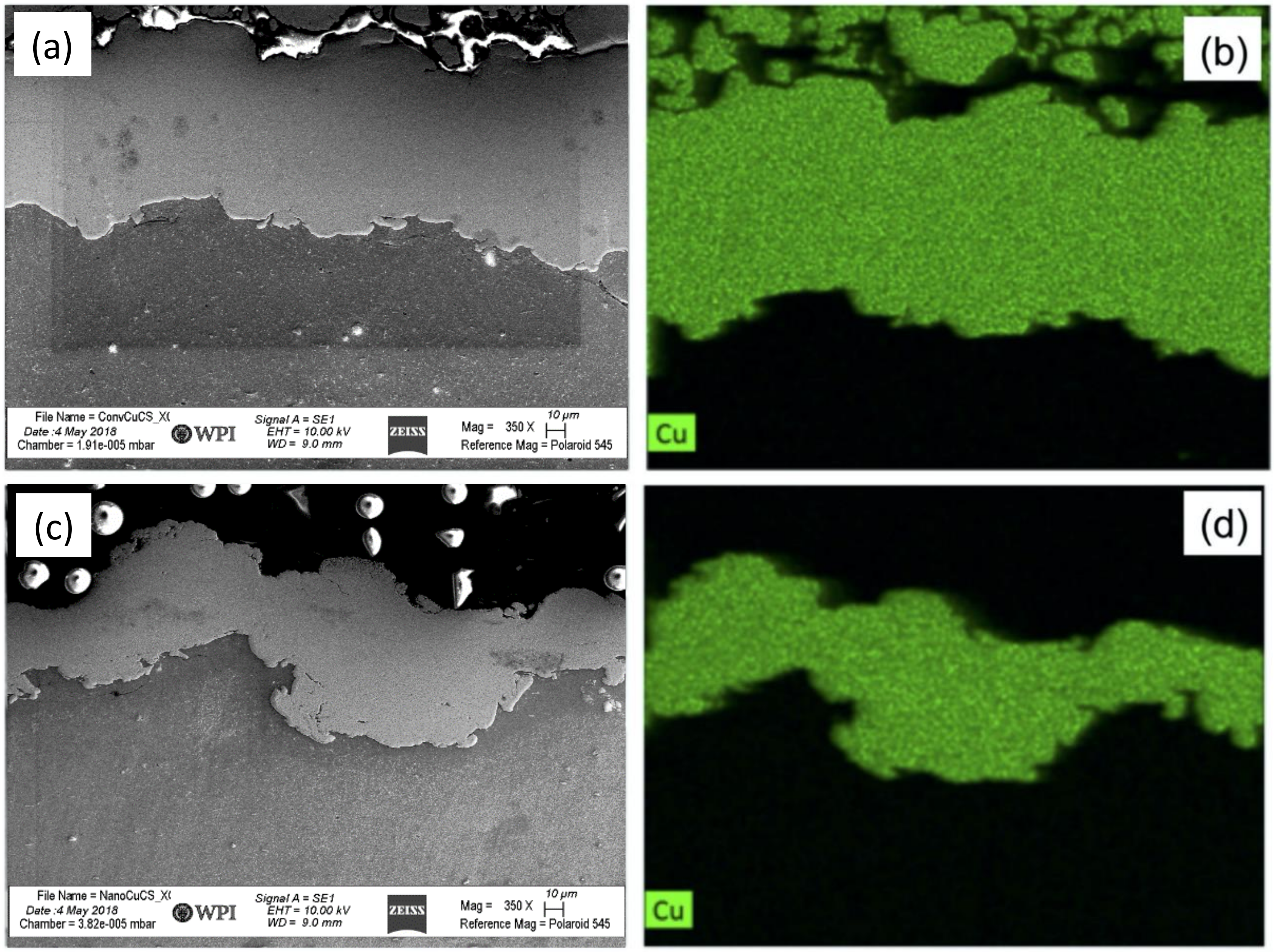
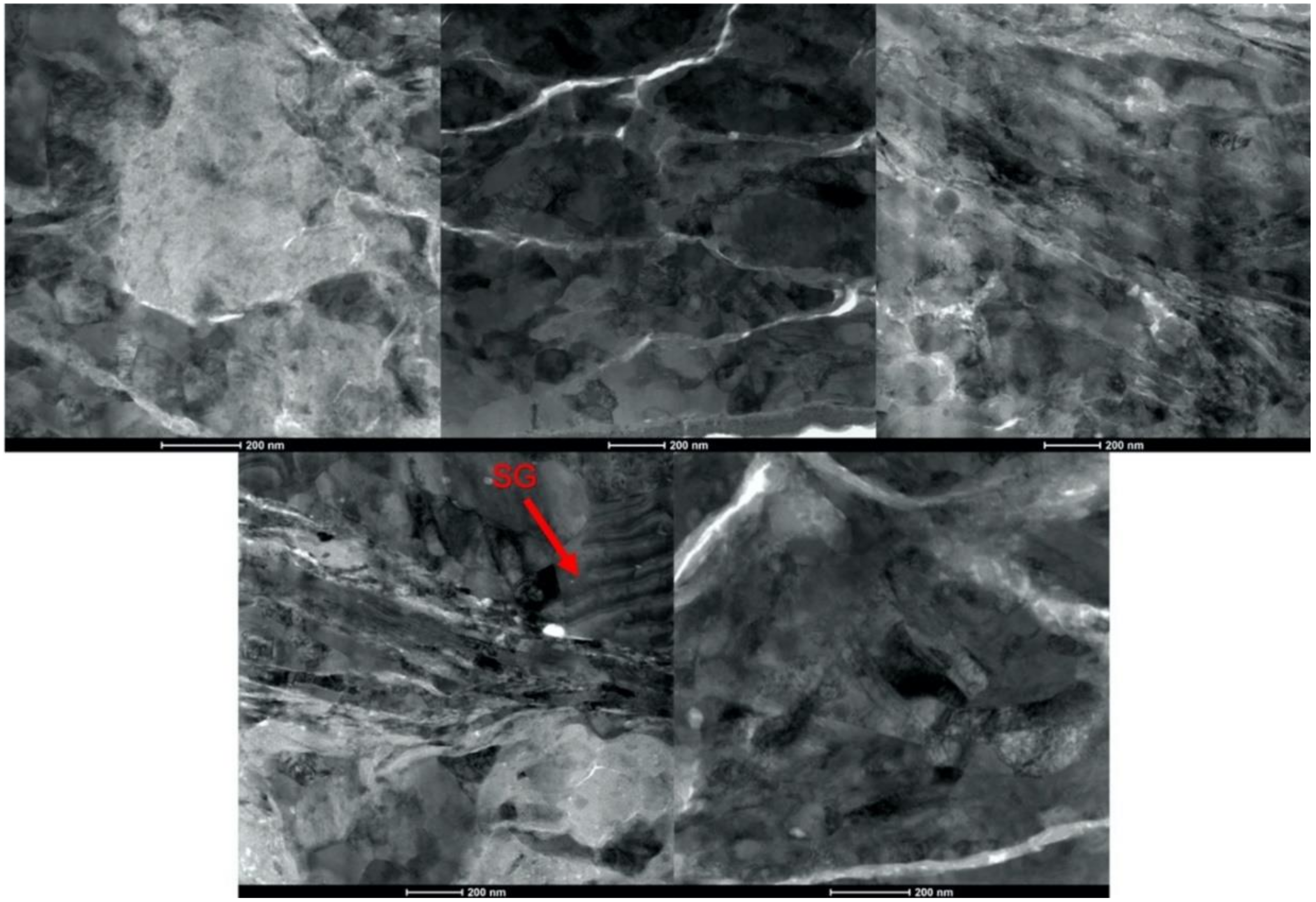
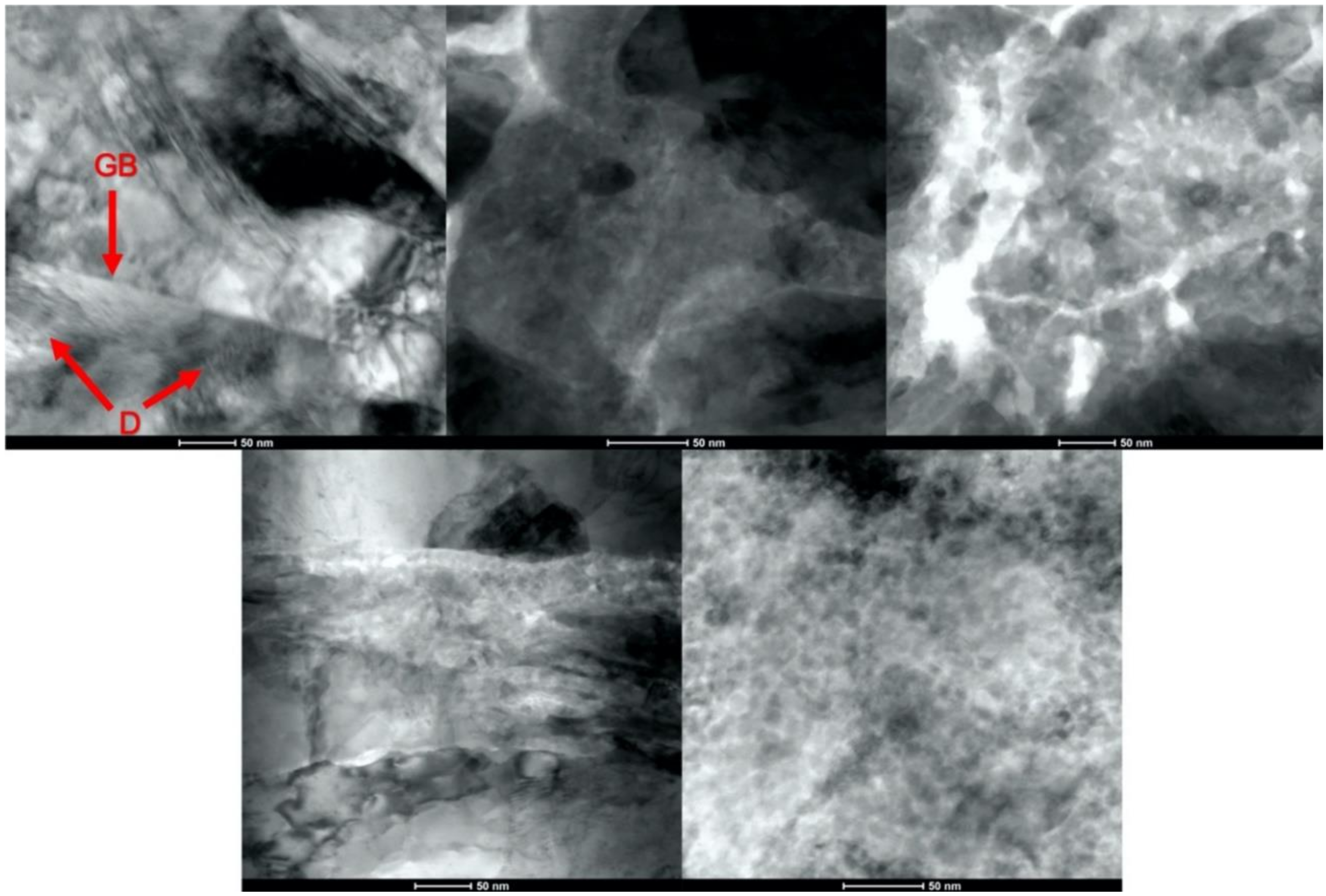
  • Analysis of the cross-sections of the Cu cold spray coatings produced via conventionally GA Cu powder and spray-dried Cu powder supported the advanced LIPIT results when considering regions of microstructural variation within severely plastically deformed particles. Characterization of the conventional Cu cold spray coatings as well as the nanostructured Cu cold spray coatings was performed using EBSD, SEM, STEM and EDS. The three regions within a deformed powder particle can be classified as (1) dynamically recrystallized at the particle/substrate interface, (2) elongated and compressed in the middle of the particle and (3) retaining microstructural features at the top of the particle. However, these gradient regions undergo continued refinement as particles subsequently impact previously deposited particles. Therefore, regions (1) and (2) remain while region (3) becomes more comparable to that of (1) as particle/particle interfaces emerge.
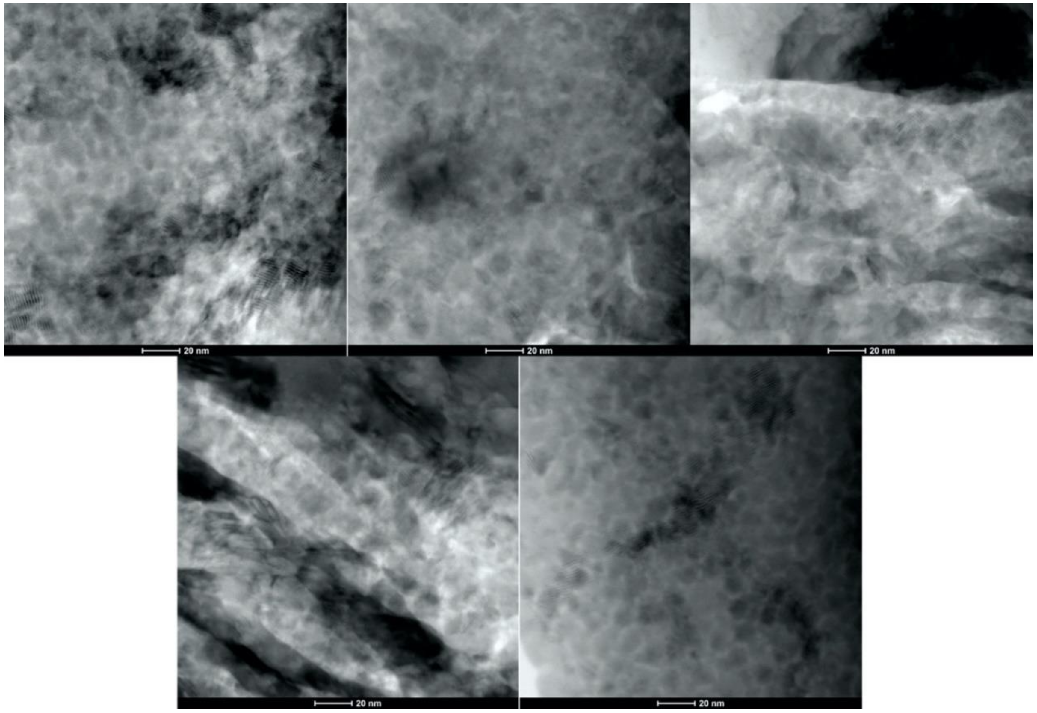
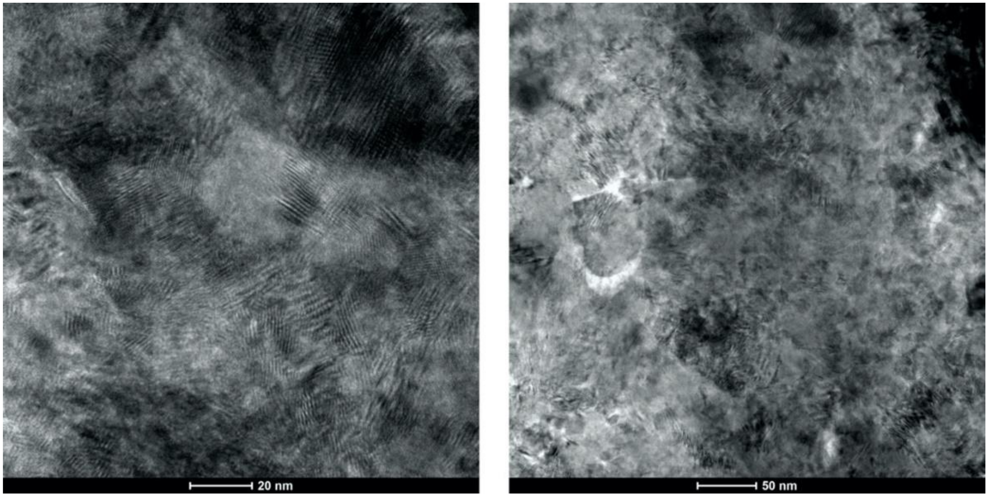
  • Microstructural analysis of the cross-sectional orientation as well as the orthogonal orientation of the Cu coatings demonstrated the fact that the conventional Cu coating had a larger grain size than the nanostructured material. This was shown to be the case regardless of orientation relative to the spray direction. The grain size of the conventional coating in the cross-sectional orientation was found to be 0.57 μm, while the grain size in the orthogonal orientation relative to the spray direction was found to be 0.90 μm. STEM revealed nanoscale grains within the nanostructured coating that were less than the initial feature size of the spray-dried Cu powder. Twinning and dislocations could also be observed via STEM. The decrease in grain size within the nanostructured Cu coating illustrates the occurrence of grain refinement even when unconventional feedstock is used in cold spray processing.
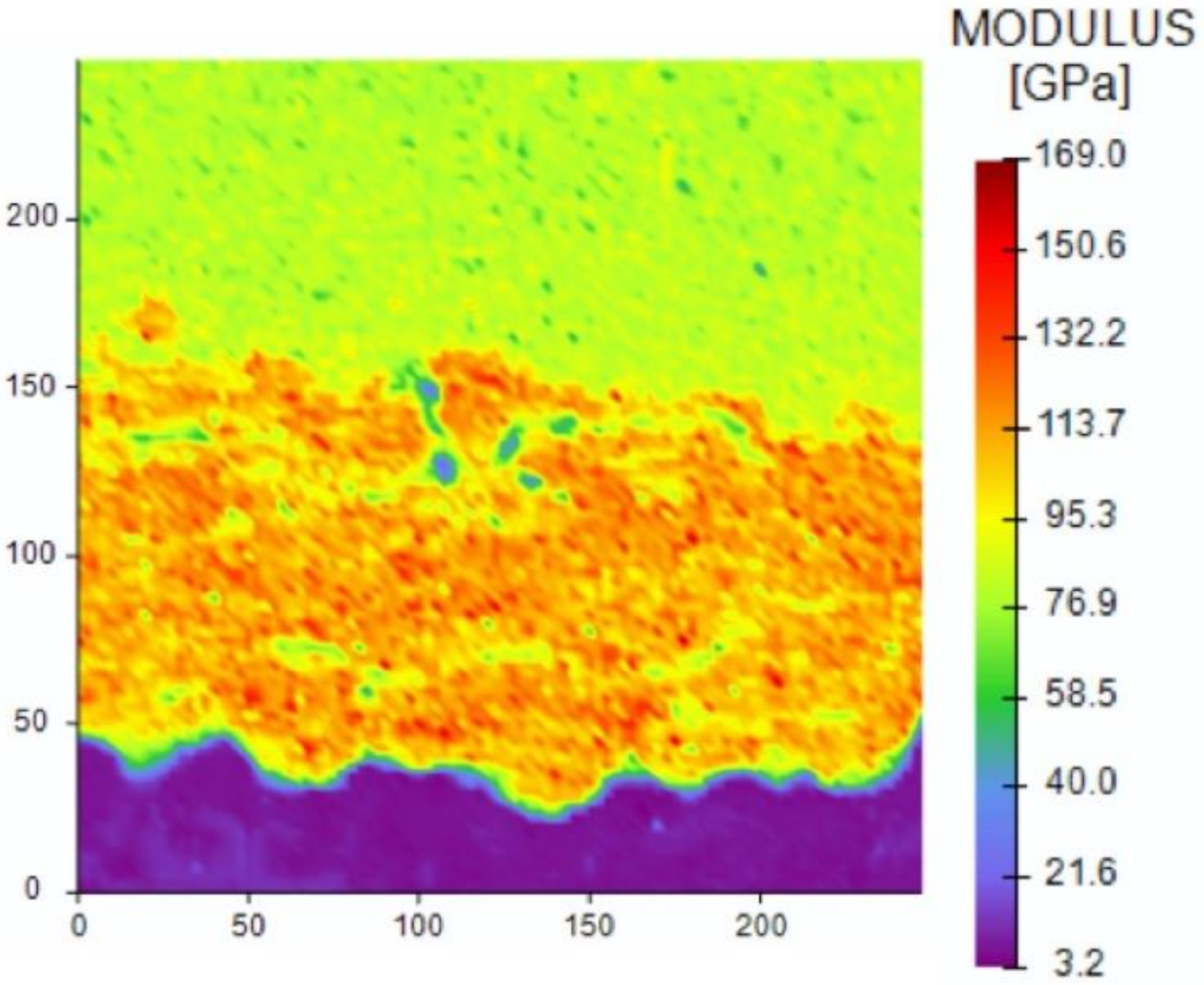
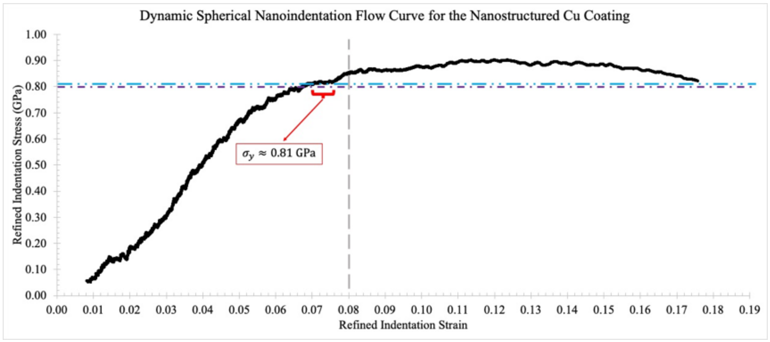
  • Nanomechanical indentation testing measured the hardness of the two cold sprayed coatings in the orthogonal orientation. The hardness of the nanostructured Cu coating was found to be greater than the hardness of the conventional Cu coating. Specifically, the hardness of the nanostructured Cu coating in the orthogonal orientation was found to be 2.37 GPa, whereas the conventional Cu coating in the orthogonal orientation had a hardness of 2.01 GPa. These findings are consistent with the Hall–Petch relation. Future work relating the hardness values to the microstructural feature size via the Hall–Petch relation should be entertained in so far as derived feature sizes could be considered in the context of antipathogenic efficacy. For example, smaller feature sizes yield a greater concentration of grain boundaries within a given area. Since pathogens are killed/inactivated via a contact killing/inactivation mechanism, which is believed to be related to Cu ion diffusion, future research could consider the energetics of grain boundaries in relation to Cu ion diffusion and therefore pathogen kill/inactivation rate. Preliminary calculations found that grain-boundary mediated ion diffusion was an order of magnitude greater than the dislocation pipe diffusion contribution to the effective atomic diffusivity.

Author Contributions

Conceptualization, B.C.S., K.S., M.A.G. and D.L.C.; methodology, B.C.S., K.L.S., M.A.G. and D.L.C.; software, B.C.S. and M.A.G.; validation, B.C.S. and M.A.G.; formal analysis, B.C.S., K.L.S., M.A.G. and D.L.C.; investigation, B.C.S., K.L.S., M.A.G. and D.L.C.; data curation, B.C.S., M.A.G. and K.L.S.; writing—original draft preparation, B.C.S.; writing—review and editing, B.C.S., M.A.G. and D.L.C.; visualization, B.C.S., M.A.G., K.L.S. and D.L.C.; supervision, D.L.C. All authors have read and agreed to the published version of the manuscript.

Funding

This research was funded by U.S. Army Research Laboratory (ARL), grant number W911NF-10-2-0098.

Acknowledgments

Thank you to Jack A. Grubbs (WPI), Christopher J. Massar (WPI) and Emily Molstad (Solvus Global, LLC) for reviewing an earlier draft. Thank you to past co-authors who elected to publish our earlier work in open access journals, which has enabled us to recall and modify earlier figures for use in this paper. Previous coauthors include Victor K. Champagne, Jr. (ARL), Yanggang Wang (WPI), Brajendra Mishra (WPI), Alexander Carl (WPI), Ronald Grimm (WPI), Alino Te (Solvus Global, LLC), Lindsay Lozeau (WPI), Richard Sisson (WPI), Baillie Haddad (VRC Metal Systems, LLC), Christopher Brown (WPI), Jeremy Schreiber (PSU), Tim Eden (PSU), Caitlin Walde (Solvus Global, LLC), Swetaparna Mohanty (UMass Amherst) and Jae-Hwang Lee (UMass Amherst).

Conflicts of Interest

The authors declare no conflict of interest. The funders had no role in the design of the study; in the collection, analyses, or interpretation of data; in the writing of the manuscript, or in the decision to publish the results.

References

  1. Bhattiprolu, V.S.; Johnson, K.W.; Ozdemir, O.C.; Crawford, G.A. Influence of feedstock powder and cold spray processing parameters on microstructure and mechanical properties of Ti-6Al-4V cold spray depositions. Surf. Coat. Technol. 2018. [Google Scholar] [CrossRef]
  2. Tang, J.; Zhao, Z.; Li, N.; Qiu, X.; Shen, Y.; Cui, X.; Du, H.; Wang, J.; Xiong, T. Influence of feedstock powder on microstructure and mechanical properties of Ta cold spray depositions. Surf. Coat. Technol. 2019. [Google Scholar] [CrossRef]
  3. Bhattiprolu, V.S.; Johnson, K.W.; Crawford, G.A. Influence of powder microstructure on the microstructural evolution of as-sprayed and heat treated cold-sprayed Ti-6Al-4V coatings. J. Therm. Spray Technol. 2019. [Google Scholar] [CrossRef]
  4. Bracker, G.P.; Hodges, E.; Scott, M.; Berdos, R.; Rigali, J.; Champagne, V.K.; Hyers, R.W. Electroplating powder for cold spray applications. In The Minerals, Metals and Materials Series; Springer: Berlin, Germany, 2020. [Google Scholar]
  5. Li, Y.J.; Luo, X.T.; Li, C.J. Dependency of deposition behavior, microstructure and properties of cold sprayed Cu on morphology and porosity of the powder. Surf. Coat. Technol. 2017. [Google Scholar] [CrossRef]
  6. Koivuluoto, H.; Vuoristo, P. Effect of powder type and composition on structure and mechanical properties of Cu+Al2O3 coatings prepared by using low-pressure cold spray process. J. Therm. Spray Technol. 2010. [Google Scholar] [CrossRef]
  7. Huang, R.; Ma, W.; Fukanuma, H. Development of ultra-strong adhesive strength coatings using cold spray. Surf. Coat. Technol. 2014. [Google Scholar] [CrossRef]
  8. Hassani-Gangaraj, M.; Veysset, D.; Champagne, V.K.; Nelson, K.A.; Schuh, C.A. Adiabatic shear instability is not necessary for adhesion in cold spray. Acta Mater. 2018. [Google Scholar] [CrossRef]
  9. Assadi, H.; Gärtner, F.; Klassen, T.; Kreye, H. Comment on ‘Adiabatic shear instability is not necessary for adhesion in cold spray’. Scr. Mater. 2019, 162, 512–514. [Google Scholar] [CrossRef]
  10. Hassani-Gangaraj, M.; Veysset, D.; Champagne, V.K.; Nelson, K.A.; Schuh, C.A. Response to Comment on “Adiabatic shear instability is not necessary for adhesion in cold spray”. Scr. Mater. 2019, 162, 515–519. [Google Scholar] [CrossRef]
  11. Raletz, F.; Vardelle, M.; Ezo’o, G. Critical particle velocity under cold spray conditions. Surf. Coat. Technol. 2006. [Google Scholar] [CrossRef]
  12. Hassani-Gangaraj, M.; Veysset, D.; Nelson, K.A.; Schuh, C.A. Melt-driven erosion in microparticle impact. Nat. Commun. 2018. [Google Scholar] [CrossRef] [PubMed]
  13. Li, C.J.; Wang, H.T.; Zhang, Q.; Yang, G.J.; Li, W.Y.; Liao, H.L. Influence of spray materials and their surface oxidation on the critical velocity in cold spraying. J. Therm. Spray. Technol. 2010, 19, 95–101. [Google Scholar] [CrossRef]
  14. Moridi, A.; Hassani-Gangaraj, S.M.; Guagliano, M. A hybrid approach to determine critical and erosion velocities in the cold spray process. Appl. Surf. Sci. 2013. [Google Scholar] [CrossRef]
  15. Koivuluoto, H.; Coleman, A.; Murray, K.; Kearns, M.; Vuoristo, P. High pressure cold sprayed (HPCS) and low pressure cold sprayed (LPCS) coatings prepared from OFHC Cu feedstock: Overview from powder characteristics to coating properties. J. Therm. Spray Technol. 2012, 21, 1065–1075. [Google Scholar] [CrossRef]
  16. Li, W.Y.; Zhang, D.D.; Huang, C.J.; Yin, S.; Yu, M.; Wang, F.F.; Liao, H.L. Modelling of impact behaviour of cold spray particles: Review. Surf. Eng. 2014. [Google Scholar] [CrossRef]
  17. Li, W.Y.; Zhang, C.; Li, C.J.; Liao, H. Modeling aspects of high velocity impact of particles in cold spraying by explicit finite element analysis. J. Therm. Spray Technol. 2009. [Google Scholar] [CrossRef]
  18. Sundberg, K. Application of Materials Characterization, Efficacy Testing, and Modeling Methods on Copper Cold Spray Coatings for Optimized Antimicrobial Properties; Worcester Polytechnic Institute: Worcester, MA, USA, 2019. [Google Scholar]
  19. Imbriglio, S.I.; Hassani-Gangaraj, M.; Veysset, D.; Aghasibeig, M.; Gauvin, R.; Nelson, K.A.; Schuh, C.A.; Chromik, R.R. Adhesion strength of titanium particles to alumina substrates: A combined cold spray and LIPIT study. Surf. Coat. Technol. 2019. [Google Scholar] [CrossRef]
  20. Zou, Y.; Qin, W.; Irissou, E.; Legoux, J.G.; Yue, S.; Szpunar, J.A. Dynamic recrystallization in the particle/particle interfacial region of cold-sprayed nickel coating: Electron backscatter diffraction characterization. Scr. Mater. 2009. [Google Scholar] [CrossRef]
  21. Cunningham, R.; Narra, S.P.; Ozturk, T.; Beuth, J.; Rollett, A.D. Evaluating the effect of processing parameters on porosity in electron beam melted Ti-6Al-4V via synchrotron X-ray microtomography. JOM 2016. [Google Scholar] [CrossRef]
  22. Markusson, L. Powder Characterization for Additive Manufactering Processes; Lulea University of Technology: Lulea, Sweeden, 2017. [Google Scholar]
  23. Champagne, V.; Sundberg, K.; Helfritch, D. Kinetically deposited copper antimicrobial surfaces. Coatings 2019, 9, 257. [Google Scholar] [CrossRef] [Green Version]
  24. Sundberg, K.; Champagne, V.; McNally, B.; Helfritch, D.; Sisson, R. Effectiveness of nanomaterial copper cold spray surfaces on inactivation of influenza A virus. J. Biotechnol. Biomater. 2015, 22, 16753–16763. [Google Scholar]
  25. Sundberg, K.; Wang, Y.; Mishra, B.; Carl, A.; Grimm, R.; Te, A.; Lozeau, L.; Sousa, B.; Sisson, R.; Cote, D. The effect of corrosion on conventional and nanomaterial copper cold spray surfaces for antimicrobial applications. Biomed. J. Sci. Tech. Res. 2019. [Google Scholar] [CrossRef]
  26. Sousa, B.; Sundberg, K.; Massar, C.; Champagne, V.; Cote, D. Spherical nanomechanical characterization of novel nanocrystalline Cu cold spray manufactured materials. In Proceedings of the APS March Meeting 2019, Boston, MA, USA, 4–8 March 2019. [Google Scholar]
  27. Sundberg, K.; Gleason, M.; Haddad, B.; Champagne, V.K.; Brown, C.; Sisson, R.D.; Cote, D. The effect of nano-scale surface roughness on copper cold spray inactivation of influenza A virus. Int. J. Nanotechnol. Med. Eng. 2019, 4, 33–40. [Google Scholar]
  28. Global Action Plan on Antimicrobial Resistance. Microbe Mag. 2015. [CrossRef]
  29. Ventola, C.L. The antibiotic resistance: Part 1: Causes and threats. P&T 2015, 40, 277–283. [Google Scholar]
  30. Michael, C.A.; Dominey-Howes, D.; Labbate, M. The antimicrobial resistance crisis: Causes, consequences, and management. Front. Public Heal. 2014, 2, 145. [Google Scholar] [CrossRef]
  31. Gross, M. Antibiotics in crisis. Curr. Biol. 2013. [Google Scholar] [CrossRef] [Green Version]
  32. Piddock, L.J.V. The crisis of no new antibiotics-what is the way forward? Lancet Infect. Dis. 2012, 12, 249–253. [Google Scholar] [CrossRef]
  33. Sikder, P.; Grice, C.R.; Lin, B.; Goel, V.K.; Bhaduri, S.B. Single-phase, antibacterial trimagnesium phosphate hydrate coatings on polyetheretherketone (PEEK) implants by rapid microwave irradiation technique. ACS Biomater. Sci. Eng. 2018. [Google Scholar] [CrossRef]
  34. Beyth, N.; Houri-Haddad, Y.; Domb, A.; Khan, W.; Hazan, R. Alternative antimicrobial approach: Nano-antimicrobial materials. Evidence Based Complement. Altern. Med. 2015, 16. [Google Scholar] [CrossRef] [Green Version]
  35. Gansukh, E.; Anthonydhason, V.; Jung, S.; Kim, D.H.; Muthu, M.; Gopal, J.; Chun, S. Nanotherapeutic anti-influenza solutions: Current knowledge and future challenges. J. Clust. Sci. 2018, 29, 933–941. [Google Scholar] [CrossRef]
  36. Gould, I.M.; Bal, A.M. New antibiotic agents in the pipeline and how hey can help overcome microbial resistance. Virulence 2013. [Google Scholar] [CrossRef] [Green Version]
  37. Golkar, Z.; Bagasra, O.; Gene Pace, D. Bacteriophage therapy: A potential solution for the antibiotic resistance crisis. J. Infect. Dev. Ctries. 2014, 8, 129–136. [Google Scholar] [CrossRef]
  38. Gagne, E. Regulation of microRNA-199 Upon Pseudomonas Aeruginosa Infection in Zebrafifish; University of Maine: Orono, ME, USA, 2016. [Google Scholar]
  39. Mohammed, M.M.M.; Chun, D.M. Electrochemical performance of few-layer graphene nano-flake supercapacitors prepared by the vacuum kinetic spray method. Coatings 2018, 8, 302. [Google Scholar] [CrossRef] [Green Version]
  40. Oliver, W.C.; Pharr, G.M. An improved technique for determining hardness and elastic modulus using load and displacement sensing indentation experiments. J. Mater. Res. 1992, 7, 1564–1583. [Google Scholar] [CrossRef]
  41. Oliver, W.C.; Pharr, G.M. Measurement of hardness and elastic modulus by instrumented indentation: Advances in understanding and refinements to methodology. J. Mater. Res. 2004. [Google Scholar] [CrossRef]
  42. Leitner, A.; Maier-Kiener, V.; Kiener, D. Essential refinements of spherical nanoindentation protocols for the reliable determination of mechanical flow curves. Mater. Des. 2018, 146, 69–80. [Google Scholar] [CrossRef]
  43. Chen, Q.; Alizadeh, A.; Xie, W.; Wang, X.; Champagne, V.; Gouldstone, A.; Lee, J.H.; Müftü, S. High-strain-rate material behavior and adiabatic material instability in impact of micron-scale Al-6061 particles. J. Therm. Spray Technol. 2018. [Google Scholar] [CrossRef]
  44. Xie, W.; Alizadeh-Dehkharghani, A.; Chen, Q.; Champagne, V.K.; Wang, X.; Nardi, A.T.; Kooi, S.; Müftü, S.; Lee, J.-H. Dynamics and extreme plasticity of metallic microparticles in supersonic collisions. Sci. Rep. 2017. [Google Scholar] [CrossRef]
  45. Carl, A.D.; Kalan, R.E.; Obayemi, J.D.; Kana, M.G.Z.; Soboyejo, W.O.; Grimm, R.L. Synthesis and characterization of alkylamine-functionalized Si(111) for perovskite adhesion with minimal interfacial oxidation or electronic defects. ACS Appl. Mater. Interfaces 2017. [Google Scholar] [CrossRef]
  46. Walton, J.; Wincott, P.; Fairley, N.; Carrick, A. Peak Fitting with CasaXPS: A Casa Pocket Book; Accolyte Science: Knutsford, UK, 2010. [Google Scholar]
  47. Belsito, D. Application of Computational Thermodynamic and Solidification Kinetics to Cold Sprayable Powder Alloy Design; Worcester Polytechnic Institute: Worcester, MA, USA, 2014. [Google Scholar]
  48. Davis, J.R. Solidifcation Structures of Copper Alloy Ingots. In Copper and Copper Alloys; ASM International: Materials Park, OH, USA, 2001; pp. 360–368. [Google Scholar]
  49. Chen, K.C.; Wu, W.W.; Liao, C.N.; Chen, L.J.; Tu, K.N. Observation of atomic diffusion at twin-modified grain boundaries in copper. Science 2008. [Google Scholar] [CrossRef] [PubMed] [Green Version]
  50. Liao, X.Z.; Zhao, Y.H.; Srinivasan, S.G.; Zhu, Y.T.; Valiev, R.Z.; Gunderov, D.V. Deformation twinning in nanocrystalline copper at room temperature and low strain rate. Appl. Phys. Lett. 2004. [Google Scholar] [CrossRef] [Green Version]
  51. Meyers, M.A.; Andrade, U.R.; Chokshi, A.H. The effect of grain size on the high-strain, high-strain-rate behavior of copper. Metall. Mater. Trans. A 1995. [Google Scholar] [CrossRef]
  52. Poirier, D.; Legoux, J.G.; Vo, P.; Blais, B.; Giallonardo, J.D.; Keech, P.G. Powder development and qualification for high-performance cold spray copper coatings on steel substrates. J. Therm. Spray Technol. 2019. [Google Scholar] [CrossRef]
  53. Kang, N.; Coddet, P.; Liao, H.; Coddet, C. Cold gas dynamic spraying of a novel micro-alloyed copper: Microstructure, mechanical properties. J. Alloys Compd. 2016. [Google Scholar] [CrossRef]
  54. King, P.C.; Zahiri, S.H.; Jahedi, M. Microstructural refinement within a cold-sprayed copper particle. Metall. Mater. Trans. A Phys. Metall. Mater. Sci. 2009. [Google Scholar] [CrossRef]
  55. King, P.C.; Bae, G.; Zahiri, S.H.; Jahedi, M.; Lee, C. An experimental and finite element study of cold spray copper impact onto two aluminum substrates. J. Therm. Spray Technol. 2010, 19, 620–634. [Google Scholar] [CrossRef]
  56. King, P.C.; Zahiri, S.H.; Jahedi, M. Focused ion beam micro-dissection of cold-sprayed particles. Acta Mater. 2008. [Google Scholar] [CrossRef]
  57. King, P.C.; Jahedi, M. Relationship between particle size and deformation in the cold spray process. Appl. Surf. Sci. 2010. [Google Scholar] [CrossRef]
  58. Feng, Y.; Li, W.; Guo, C.; Gong, M.; Yang, K. Mechanical property improvement induced by nanoscaled deformation twins in cold-sprayed Cu coatings. Mater. Sci. Eng. A 2018. [Google Scholar] [CrossRef]
  59. Borchers, C.; Gärtner, F.; Stoltenhoff, T.; Assadi, H.; Kreye, H. Microstructural and macroscopic properties of cold sprayed copper coatings. J. Appl. Phys. 2003. [Google Scholar] [CrossRef]
  60. Hassani-Gangaraj, S.M.; Moridi, A.; Guagliano, M. Critical review of corrosion protection by cold spray coatings. Surf. Eng. 2015, 31, 11. [Google Scholar] [CrossRef]
  61. Cullity, B.D.; Stock, S.R. Elements of X-ray Diffraction, 3rd ed.; Prentice Hall: Upper Saddle River, NJ, USA, 2001. [Google Scholar]
  62. Kang, K.; Yoon, S.; Ji, Y.; Lee, C. Oxidation dependency of critical velocity for aluminum feedstock deposition in kinetic spraying process. Mater. Sci. Eng. A 2008. [Google Scholar] [CrossRef]
  63. Hans, M.; Erbe, A.; Mathews, S.; Chen, Y.; Solioz, M.; Mücklich, F. Role of copper oxides in contact killing of bacteria. Langmuir 2013. [Google Scholar] [CrossRef]
  64. Palmer, D.A. Solubility measurements of crystalline Cu2O in aqueous solution as a function of temperature and pH. J. Solution Chem. 2011. [Google Scholar] [CrossRef]
  65. Mathews, S.; Hans, M.; Mücklich, F.; Solioz, M. Contact killing of bacteria on copper is suppressed if bacterial-metal contact is prevented and is induced on iron by copper ions. Appl. Environ. Microbiol. 2013. [Google Scholar] [CrossRef] [Green Version]
  66. Mathews, S.; Kumar, R.; Solioz, M. Copper reduction and contact killing of bacteria by iron surfaces. Appl. Environ. Microbiol. 2015. [Google Scholar] [CrossRef] [Green Version]
  67. Rahmati, S.; Zúñiga, A.; Jodoin, B.; Veiga, R.G.A. Deformation of copper particles upon impact: A molecular dynamics study of cold spray. Comput. Mater. Sci. 2020. [Google Scholar] [CrossRef]
  68. Suresh, S.; Lee, S.W.; Aindow, M.; Brody, H.D.; Champagne, V.K.; Dongare, A.M. Unraveling the mesoscale evolution of microstructure during supersonic impact of aluminum powder particles. Sci. Rep. 2018. [Google Scholar] [CrossRef]
  69. Li, C.J.; Li, W.Y.; Liao, H. Examination of the critical velocity for deposition of particles in cold spraying. J. Therm. Spray Technol. 2006, 15, 212–222. [Google Scholar] [CrossRef]
  70. Hassani-Gangaraj, M.; Veysset, D.; Nelson, K.A.; Schuh, C.A. In-situ observations of single micro-particle impact bonding. Scr. Mater. 2018. [Google Scholar] [CrossRef]
  71. Viscusi, A.; Astarita, A.; Gatta, R.D.; Rubino, F. A perspective review on the bonding mechanisms in cold gas dynamic spray. Surf. Eng. 2019, 35, 743–771. [Google Scholar] [CrossRef]
  72. Lee, C.; Kim, J. Microstructure of kinetic spray coatings: A review. J. Therm. Spray Technol. 2015, 24, 592–610. [Google Scholar] [CrossRef]
  73. Grujicic, M.; Saylor, J.R.; Beasley, D.E.; DeRosset, W.S.; Helfritch, D. Computational analysis of the interfacial bonding between feed-powder particles and the substrate in the cold-gas dynamic-spray process. Appl. Surf. Sci. 2003. [Google Scholar] [CrossRef]
  74. Klinkov, S.V.; Kosarev, V.F.; Rein, M. Cold spray deposition: Significance of particle impact phenomena. Aerosp. Sci. Technol. 2005. [Google Scholar] [CrossRef]
  75. Lee, J.H.; Loya, P.E.; Lou, J.; Thomas, E.L. Dynamic mechanical behavior of multilayer graphene via supersonic projectile penetration. Science 2014. [Google Scholar] [CrossRef]
  76. Villafuerte, J. Modern Cold Spray: Materials, Process, and Applications; Springer: Berlin, Germany, 2015; ISBN 9783319167725. [Google Scholar]
  77. Fukumoto, M.; Terada, H.; Mashiko, M.; Sato, K.; Yamada, M.; Yamaguchi, E. Deposition of copper fine particle by cold spray process. Mater. Trans. 2009. [Google Scholar] [CrossRef] [Green Version]
  78. Kim, Y.K.; Kim, K.S.; Kim, H.J.; Park, C.H.; Lee, K.A. Microstructure and room temperature compressive deformation behavior of cold-sprayed high-strength Cu bulk material. J. Therm. Spray Technol. 2017. [Google Scholar] [CrossRef]
  79. Yin, S.; Suo, X.; Su, J.; Guo, Z.; Liao, H.; Wang, X. Effects of substrate hardness and spray angle on the deposition behavior of cold-sprayed Ti particles. J. Therm. Spray Technol. 2014, 23, 76–83. [Google Scholar] [CrossRef]
  80. Huang, K.; Logé, R.E. A review of dynamic recrystallization phenomena in metallic materials. Mater. Des. 2016, 111, 548–574. [Google Scholar] [CrossRef]
  81. Xie, Y.; Chen, C.; Planche, M.P.; Deng, S.; Huang, R.; Ren, Z.; Liao, H. Strengthened peening effect on metallurgical bonding formation in cold spray additive manufacturing. J. Therm. Spray Technol. 2019. [Google Scholar] [CrossRef] [Green Version]
  82. Wang, Q.; Birbilis, N.; Zhang, M.X. Interfacial structure between particles in an aluminum deposit produced by cold spray. Mater. Lett. 2011. [Google Scholar] [CrossRef]
  83. Balani, K.; Agarwal, A.; Seal, S.; Karthikeyan, J. Transmission electron microscopy of cold sprayed 1100 aluminum coating. Scr. Mater. 2005. [Google Scholar] [CrossRef]
  84. Hou, X.D.; Bushby, A.J.; Jennett, N.M. Study of the interaction between the indentation size effect and Hall-Petch effect with spherical indenters on annealed polycrystalline copper. J. Phys. D. Appl. Phys. 2008. [Google Scholar] [CrossRef]
  85. Hansen, N. Hall-Petch relation and boundary strengthening. Scr. Mater. 2004. [Google Scholar] [CrossRef]
  86. Trelewicz, J.R.; Schuh, C.A. The Hall-Petch breakdown in nanocrystalline metals: A crossover to glass-like deformation. Acta Mater. 2007. [Google Scholar] [CrossRef]
  87. Aristia, G.; Hoa, L.Q.; Bäßler, R. Corrosion of carbon steel in artificial geothermal brine: Influence of carbon dioxide at 70 °C and 150 °C. Materials 2019, 12, 3801. [Google Scholar] [CrossRef] [Green Version]
  88. Koivuluoto Heli, H.; Bolelli, G.; Lusvarghi, L.; Casadei, F.; Vuoristo, P. Corrosion resistance of cold-sprayed Ta coatings in very aggressive conditions. Surf. Coat. Technol. 2010. [Google Scholar] [CrossRef]
  89. Champagne, V.K.; Helfritch, D.J. A demonstration of the antimicrobial effectiveness of various copper surfaces. J. Biol. Eng. 2013. [Google Scholar] [CrossRef] [Green Version]
  90. Bard, A.J.; Faulkner, L.R. Electrochemical Methods: Fundamentals and Applications; Wiley: Hoboken, NJ, USA, 1980; ISBN 3175723993. [Google Scholar]
  91. Electrochemical Impedance: Analysis and Interpretation; American Society for Testing Materials: West Conshohocken, PA, USA, 1993; ISBN 0803118619.
  92. Michels, H.T.; Wilks, S.A.; Noyce, J.O.; Keevil, C.W. Copper alloys for human infectious disease control. Mater. Sci. Technol. 2005, 1, 12. [Google Scholar]
  93. Vincent, M.; Duval, R.E.; Hartemann, P.; Engels-Deutsch, M. Contact killing and antimicrobial properties of copper. J. Appl. Microbiol. 2018. [Google Scholar] [CrossRef] [PubMed] [Green Version]
  94. Warnes, S.L.; Green, S.M.; Michels, H.T.; Keevil, C.W. Biocidal efficacy of copper alloys against pathogenic enterococci involves degradation of genomic and plasmid DNAs. Appl. Environ. Microbiol. 2010. [Google Scholar] [CrossRef] [PubMed] [Green Version]
  95. Santo, C.E.; Lam, E.W.; Elowsky, C.G.; Quaranta, D.; Domaille, D.W.; Chang, C.J.; Grass, G. Bacterial killing by dry metallic copper surfaces. Appl. Environ. Microbiol. 2011. [Google Scholar] [CrossRef] [PubMed] [Green Version]
  96. Fujimori, Y.; Sato, T.; Hayata, T.; Nagao, T.; Nakayam, M.; Nakayam, T.; Sugamat, R.; Suzuki, K. Novel antiviral characteristics of nanosized copper(i) iodide particles showing inactivation activity against 2009 pandemic H1N1 influenza virus. Appl. Environ. Microbiol. 2012. [Google Scholar] [CrossRef] [PubMed] [Green Version]
  97. Macomber, L.; Imlay, J.A. The iron-sulfur clusters of dehydratases are primary intracellular targets of copper toxicity. Proc. Natl. Acad. Sci. USA 2009. [Google Scholar] [CrossRef] [Green Version]
  98. Klinger, L.; Rabkin, E. Diffusion along the grain boundaries in crystals with dislocations. Interface Sci. 1998. [Google Scholar] [CrossRef]
  99. Legros, M.; Dehm, G.; Arzt, E.; Balk, T.J. Observation of giant diffusivity along dislocation cores. Science 2008. [Google Scholar] [CrossRef]
  100. Ovid’ko, I.A.; Sheinerman, A.G. Grain-boundary dislocations and enhanced diffusion in nanocrystalline bulk materials and films. Philos. Mag. 2003. [Google Scholar] [CrossRef] [Green Version]
  101. Lu, K.; Huo, C.F.; He, Y.; Yin, J.; Liu, J.; Peng, Q.; Guo, W.P.; Yang, Y.; Li, Y.W.; Wen, X.D. Grain boundary plays a key role in carbon diffusion in carbon irons revealed by a reaxff study. J. Phys. Chem. C 2018. [Google Scholar] [CrossRef]
  102. Parmar, V.; Changela, K.; Srinivas, B.; Sankar, M.M.; Mohanty, S.; Panigrahi, S.K.; Hariharan, K.; Kalyanasundaram, D. Relationship between dislocation density and antibacterial activity of cryo-rolled and cold-rolled copper. Materials 2019, 12, 200. [Google Scholar] [CrossRef] [Green Version]
  103. Da Silva, F.S.; Cinca, N.; Dosta, S.; Cano, I.G.; Guilemany, J.M.; Caires, C.S.A.; Lima, A.R.; Silva, C.M.; Oliveira, S.L.; Caires, A.R.L.; et al. Corrosion resistance and antibacterial properties of copper coating deposited by cold gas spray. Surf. Coat. Technol. 2019. [Google Scholar] [CrossRef]
  104. Landau, P.; Osovski, S.; Venkert, A.; Gärtnerová, V.; Rittel, D. The genesis of adiabatic shear bands. Sci. Rep. 2016. [Google Scholar] [CrossRef] [PubMed] [Green Version]
  105. De Orio, R.L. Electromigration Modeling and Simulation; Vienna University of Technology: Vienna, Austria, 2010. [Google Scholar]
  106. Chen, J.; Lu, L.; Lu, K. Hardness and strain rate sensitivity of nanocrystalline Cu. Scr. Mater. 2006. [Google Scholar] [CrossRef]
  107. Choi, S.; Christiansen, C.; Cao, L.; Zhang, J.; Filippi, R.; Shen, T.; Yeap, K.B.; Ogden, S.; Zhang, H.; Fu, B.; et al. Effect of metal line width on electromigration of BEOL Cu interconnects. In Proceedings of the IEEE International Reliability Physics Symposium, Burlingame, CA, USA, 11–15 March 2018. [Google Scholar]
  108. Hutchings, I.M. The contributions of David Tabor to the science of indentation hardness. J. Mater. Res. 2009. [Google Scholar] [CrossRef]
  109. Selvamani, V.; Zareei, A.; Elkashif, A.; Maruthamuthu, M.K.; Chittiboyina, S.; Delisi, D.; Li, Z.; Cai, L.; Pol, V.G.; Seleem, M.N.; et al. Hierarchical micro/mesoporous copper structure with enhanced antimicrobial property via laser surface texturing. Adv. Mater. Interfaces 2020. [Google Scholar] [CrossRef]
  110. Van Doremalen, N.; Bushmaker, T.; Morris, D.H.; Holbrook, M.G.; Gamble, A.; Williamson, B.N.; Tamin, A.; Harcourt, J.L.; Thornburg, N.J.; Gerber, S.I.; et al. Aerosol and surface stability of SARS-CoV-2 as compared with SARS-CoV-1. N. Engl. J. Med. 2020, 382, 1564–1567. [Google Scholar] [CrossRef]
  111. Michels, H.T.; Michels, C.A. Can copper help fight COVID-19? Adv. Mater. Process. 2020, 1–4. [Google Scholar]
Figure 1. Schematic of the cold spray process, from powder to coated surface.
Crystals 10 00504 g001
Figure 2. Micrographs were observed using a HDBS electron detector for the chemically etched GA powder cross-sections as shown in (a) and (b). At the same time, similar micrographs were obtained for the spray-dried powder in (c) and (d).
Crystals 10 00504 g002
Figure 3. SDAS as a function of particle diameter obtained by way of cooling rate analysis.
Crystals 10 00504 g003
Figure 4. EBSD analysis of GA Cu powder.
Crystals 10 00504 g004
Figure 5. Micrograph of spray-dried Cu powder illustrating particle porosity. Very small particles are also found to be bound with one another on the right-most micrograph of the powder. These observations attest to the nanostructure associated with the spray-dried Cu powder.
Crystals 10 00504 g005
Figure 6. EDS analysis of GA Cu powder. O and Cu are of interest, whereas the C content follows from the chemical nature of the mounting material.
Crystals 10 00504 g006
Figure 7. EDS analysis of spray-dried Cu powder. O and Cu are of interest whereas the C content follows from the chemical nature of the mounting material.
Crystals 10 00504 g007
Figure 8. Powder X-ray diffraction (PXRD) of the spray-dried Cu powder (top) and GA Cu powder (bottom).
Crystals 10 00504 g008
Figure 9. Collision and rebound of the GA Cu particles with a high-purity Al target substrate during advanced LIPIT experimentation. Vi and Vr are also illustrated in this figure when a Vc was not reached.
Crystals 10 00504 g009
Figure 10. Vr and CoR vs. Vi for (A) GA Cu (labeled as “Solid Cu particles”) and (B) spray-dried Cu (labeled as “Nano-Cu particles”) powder.
Crystals 10 00504 g010
Figure 11. Reformulation of the Vr vs. Vi and CoR vs. Vi for GA Cu (labeled as Solid Cu) and spray-dried Cu (labeled as Nano Cu) powder.
Crystals 10 00504 g011
Figure 12. Micrographs of “as-impacted” and cross-sections of the single-particle impacts from advanced LIPIT study of a GA Cu powder particle at 701 m/s shown in (a) and (b), respectively, and spray-dried Cu powder particles at 770 m/s in (c) and (d), respectively, and spray-dried Cu powder particles at 884 m/s in (e) and (f). The black arrows are indictive of interesting bonding and deformation features (such as pore densification and particle/substrate void formation in (d) and mechanical interlocking in (b)).
Crystals 10 00504 g012
Figure 13. SEM micrographs of cross-sectioned and etched consolidated conventional Cu (a) and (b) as well as nanostructured cold sprayed Cu (c) and (d).
Crystals 10 00504 g013
Figure 14. SEM micrographs are shown herein. HDBS micrographs of the orthogonal orientation of consolidated conventional Cu is given in (A), while the nanostructured Cu is given in (B), the polished conventional Cu is given in (C), and the polished nanostructured Cu is given in (D). Field emission SEM micrographs are shown for the orthogonal orientation of the polished and etched consolidated conventional Cu in (E) and the nanostructured Cu coating in (F).
Crystals 10 00504 g014
Figure 15. (Left) presents the EBSD-derived crystallographic analysis of the conventional cold spray coating in the orthogonal orientation. (Right) presents the EBSD derived crystallographic analysis of the nanostructured cold spray coating in the orthogonal orientation.
Crystals 10 00504 g015
Figure 16. (Left) presents the EBSD-derived crystallographic analysis of the conventional cold spray coating in the cross-sectional orientation. (Right) presents the EBSD crystallographic analysis of the nanostructured cold spray coating in the cross-sectional orientation.
Crystals 10 00504 g016
Figure 17. EDS of a consolidated cross-sectional orientation of the conventional Cu coating as shown in (a) and (b). EDS of a cross-sectional orientation of the nanostructured Cu coating as shown in (c) and (d).
Crystals 10 00504 g017
Figure 18. O segregation at the interfacial boundaries using STEM and EDS.
Crystals 10 00504 g018
Figure 19. STEM micrographs of the deformed microstructure of the nanostructured cold sprayed coatings in the cross-sectional orientation. The scale bar represents 500 nm.
Crystals 10 00504 g019
Figure 20. STEM micrographs of the deformed microstructure of the nanostructured cold sprayed coatings in the cross-sectional orientation. Note that the scale bar represents 200 nm. Sub-grain (SG) formation structure is similar to prior reports [83]. This is likely attributable to the UFG Cu binder.
Crystals 10 00504 g020
Figure 21. STEM micrographs of the deformed microstructure of the nanostructured cold sprayed coatings in the cross-sectional orientation. Note that the scale bar represents 50 nm. Dislocation accumulation (D) at a prior grain boundary (GB) is similar to observations made in [83].
Crystals 10 00504 g021
Figure 22. STEM micrographs of the deformed microstructure of the nanostructured cold sprayed coatings in the cross-sectional orientation. Note that the scale bar represents 20 nm. Limited presence of dislocation defects within the regions captured in the middle micrograph on the top row and bottom right micrograph. Numerable nanoparticle/nanoparticle boundaries and interiors can be observed in the same micrographs. Elongated and deformed grains are present within the bottom left and upper right micrographs.
Crystals 10 00504 g022
Figure 23. STEM micrographs of the deformed microstructure of the nanostructured cold sprayed coatings in the cross-sectional orientation. Increased dislocation density can be observed in parts of the micrograph on the left. A large amount of atomic lattice fringes is observed in the leftmost micrograph.
Crystals 10 00504 g023
Figure 24. Modulus of elasticity countor plot. The mostly green region is the Al substrate material, the orange/yellow/red region is the Cu cold spray coating, and the purple region is the mounting resin.
Crystals 10 00504 g024
Figure 25. Electrochemical impedance spectroscopy for the nanostructured Cu coating, the conventional Cu coating and bulk/wrought Cu.
Crystals 10 00504 g025
Figure 26. Linear polarization data associated with the Cu samples studied during this work.
Crystals 10 00504 g026
Figure 27. Cu ion release assay for nanostructured Cu and conventional Cu cold sprayed samples with an Al control sample.
Crystals 10 00504 g027
Figure 28. Confocal microscopy analysis of nanostructured Cu and conventional Cu cold spray coatings. The top-left and bottom-left micrographs concern the nanostructured coating. The top-right and bottom-right micrograph and surface rendering are concerned with the conventional coating.
Crystals 10 00504 g028
Figure 29. XPS for Cu, O and Auger electron spectra in the Cu LMM region. Data for the as-manufactured Cu cold spray coating is shown in (1A) and the corroded Cu cold spray coating is shown in (1B). The data for the as-manufactured nanostructured Cu cold spray coating is shown in (2A). Data for the corroded nanostructured Cu cold spray coating is given in (2B). The as-manufactured bulk/wrought Cu is in (3A) and the corroded bulk/wrought Cu is in (3B). The dashed blue lines represent the location of each Cu and O species.
Crystals 10 00504 g029aCrystals 10 00504 g029b
Figure 30. The spherical dynamic stress–strain curve of the nanostructured Cu cold spray coating with the strain associated with hardness testing and Tabor’s relation (in gray), the σ y from analysis of the flow curve (captured in the red box), the σ y of a similarly nanostructured pure Cu with a grain size of about 20 nm (in purple) and the Hall–Petch-obtained σ y (in blue).
Crystals 10 00504 g030
Figure 31. AFM and confocal data for the nanostructured and conventional Cu cold spray coatings.
Crystals 10 00504 g031
Figure 32. 3D confocal microscopy and SEM surface analysis. The left column of images concerns the conventional Cu cold spray coating while the right column of images corresponds with the nanostructured Cu coating.
Crystals 10 00504 g032

