Article

Stable and Metastable Patterns in Chromonic Nematic Liquid Crystal Droplets Forced with Static and Dynamic Magnetic Fields

by
Jordi Ignés-Mullol
1,2,*,
Marc Mora
1,2,†,
Berta Martínez-Prat
1,2,
Ignasi Vélez-Cerón
1,2,
R. Santiago Herrera
1,2 and
Francesc Sagués
1,2
1
Departament de Ciència de Materials i Química Física, Universitat de Barcelona, 08028 Barcelona, Spain
2
Institute of Nanoscience and Nanotechnology of the University of Barcelona (IN2UB), 08028 Barcelona, Spain
*
Author to whom correspondence should be addressed.
Current address: Department of Physics and Randall Centre for Cell and Molecular Biophysics, King’s College London, London, WC2R 2LS, UK.
Crystals 2020, 10(2), 138; https://doi.org/10.3390/cryst10020138
Submission received: 30 December 2019 / Revised: 10 February 2020 / Accepted: 14 February 2020 / Published: 24 February 2020
(This article belongs to the Special Issue Patterned-Liquid-Crystal for Novel Displays)

Abstract

:
Spherical confinement of nematic liquid crystals leads to the formation of equilibrium director field configurations that include point and line defects. Driving these materials with flows or dynamic fields often results in the formation of alternative metastable states. In this article, we study the effect of magnetic field alignment, both under static and dynamic conditions, of nematic gems (nematic droplets in coexistence with the isotropic phase) and emulsified nematic droplets of a lyotropic chromonic liquid crystal. We use a custom polarizing optical microscopy assembly that incorporates a permanent magnet whose strength and orientation can be dynamically changed. By comparing simulated optical patterns with microscopy images, we measure an equilibrium twisted bipolar pattern within nematic gems that is only marginally different from the one reported for emulsified droplets. Both systems evolve to concentric configurations upon application of a static magnetic field, but behave very differently when the field is rotated. While the concentric texture within the emulsified droplets is preserved and only displays asynchronous oscillations for high rotating speeds, the nematic gems transform into a metastable untwisted bipolar configuration that is memorized by the system when the field is removed. Our results demonstrate the importance of boundary conditions in determining the dynamic behavior of confined liquid crystals even for configurations that share similar equilibrium bulk structures.

1. Introduction

Liquid crystals are anisotropic liquids that feature long-range orientational order, locally characterized by a director field, whose distortion from uniform alignment incurs in an elastic free-energy cost [1,2]. Spatial confinement of these materials often triggers the formation of patterns and complex defect configurations of the director, as a result of the interplay between the drive towards free-energy minimization and the topology imposed by boundary conditions on the enclosing container walls [3]. The presence of topological defects is often a hindrance to be avoided in LC-based applications, such as displays and electro-optical devices but, in recent years, the induction and control of defects has been recognized as an opportunity for the development of novel functional materials [4,5], often in combination with dispersed particles that organize the distortions at colloidal length scales [6]. Spherical confinement, particularly within droplets, is the simplest topology where fixed boundary conditions on the droplet surface are incompatible with a uniform director field, leading to the formation of point and line defects [7]. This confinement can be easily realized at the coexistence between the isotropic and nematic phases of a mesogen, where nematic droplets with internal orientational order are suspended within the isotropic phase. Since this coexistence is typically only realized in a narrow temperature range, emulsification of the mesogen into an immiscible liquid [8,9] or dispersion in a polymer matrix [10] are more practical strategies to stabilize such configurations. Materials based on dispersed liquid crystal droplets have found applications as functional materials [11,12] or biosensors [13,14].
Spherical confinement with tangential boundary conditions, which can be easily achieved using suitable surfactants for molecular liquid crystals and is entropically favored in the case of colloidal mesogens [15,16], usually results in a bipolar configuration, where the director aligns along the meridians on the droplet surface, subtended between the two poles, where surface point defects, called boojums, are stabilized. In this configuration, splay distortion dominates, which is consistent with the usual property of mesogens that the bend elastic constant is larger than both the splay and twist constants. An alternative texture, the so-called concentric (or toroidal) configuration, has been reported as a transient state in emulsified confined nematic droplets under flow conditions [17] and, more recently, in polymer-dispersed nematic liquid crystal droplets [18].
In a previous study, Jeong and co-workers [19] characterized the structure of nematic droplets of the water-based lyotropic chromonic liquid crystal (LCLC) Sunset Yellow (SSY) [20,21] emulsified in a hydrocarbon oil. These authors revealed an unusual configuration of the orientational field that exhibited a twisted bipolar (TB), rather than the usual bipolar configuration expected for planar anchoring conditions on the spherical surface. Such configuration, which endows a macroscopic chirality to these materials prepared with achiral molecules, has been observed for cholesteric liquid crystals [22], and had been predicted to be also possible for nematic liquid crystals provided the twist elastic constant is much lower than the bend and the splay constants [23], which is indeed the case for SSY [24]. Recent studies reported a similar texture in nematic droplets of SSY in coexistence with its isotropic phase (that we will call gems henceforth, to differentiate from emulsified droplets), rather than in emulsified SSY droplets. The twisted director field, which confers a chiral supramolecular order in these nematic gems of achiral molecules, leads to the transduction of a temperature gradient into mechanical rotation, a phenomenon that cannot be replicated when the SSY nematic droplets are emulsified in oil [25].
Prompted by this contrasted behavior of SSY droplets and gems under non-equilibrium conditions, in the present work we will first characterize the static TB texture within the nematic gems, seeking for differences in the director field arrangement with respect to their emulsified counterparts. We will then take advantage of the strong negative magnetic susceptibility of SSY [24] to show that both gems and droplets change to a concentric configuration upon application of a static magnetic field. Finally, we unveil remarkable differences when the magnetic field is dynamically rotated. While emulsified droplets exhibit asynchronous oscillations of the concentric texture, nematic gems feature a transition into a metastable untwisted bipolar configuration, whose stability we explore.

2. Experimental Methods

2.1. Sample Preparation

LCLC were prepared by dissolving the disodium salt of 6-hydroxy-5-[(4-sulfophenyl)azo]-2- naphtalenesulfonic acid, commonly known as Sunset Yellow FCF (SSY, Aldrich, St. Louis, MO, USA, M w = 452.37 g mol 1 ) in Milli-Q water at a ratio 0.0226 g SSY in 50 μ L of water (1.0 molal). This concentration resulted in a nematic phase at room temperature and a NI coexistence in the range 40–50 C. In order to prepare the LCLC mixture, we performed 5–6 cycles of 10 min of agitation in a lukewarm ultrasonic bath followed by 30 s of vortex agitation, until we obtained a homogeneous dark red liquid.
Solid SSY was received with a purity of about 90%, which required further purification following published protocols [19,26]. Briefly, we prepared a saturated solution (190 mg mL 1 ) of SSY in pure water. Afterwards, a volume of ice cold absolute ethanol (PanReac) similar to the volume of water was slowly added to the SSY solution to cause SSY precipitation, and the mixture was kept for two minutes in the freezer (−20 C). The precipitate was subsequently vacuum filtered, and kept in a vacuum oven at 150 C for 24 h or until dry (its weight had stabilized). This procedure was repeated twice. The purified SSY was stored in a desiccator under vacuum, until needed. We typically repeated the vacuum drying of stock purified SSY every two weeks to ensure maximum reproducibility of the experiments.
LCLC-in-oil emulsions were obtained by dispersing the LCLC mixture described above in either hexadecane [19] or in fluorinated oil. When using hexadecane, we dissolved 2 μ L of the nonionic surfactant sorbitan monooleate (Span 80, Fluka) in 35 μ L of hexadecane (99%, Sigma H6703) and added 1–2 μ L of LCLC to the oil. In order to obtain sparse LCLC droplets of a few tens of microns in diameter, a few vigorous finger taps were enough. Since hexadecane is significantly hygroscopic, concentration of SSY in the aqueous droplets increased with time, which led to a transition from the nematic to the columnar phase, or even to the drying of the LCLC. A trick to delay this process consisted in saturating the hexadecane with water prior to emulsion preparation. Briefly, we dispersed same volumes of hexadecane and pure water in a closed tube with a sonicator, and left it overnight. The two liquids were fully phase-separated by centrifugation, and the water-saturated oil was subsequently used to prepare the LCLC emulsions as described above.
In order to slow down this water loss, we resorted to hydrophobic fluorinated oils instead. When using this alternative dispersing phase, we took advantage of its inert nature to employ a droplet-generating microfluidic device built with PDMS (poly-dimethyl siloxane) using standard photolithography and soft molding techniques. The device included flow-focusing channels for droplet generation, and a chamber region with a thickness of 125 μ m for emulsion storage and direct observation of undistorted spherical SSY droplets in our custom setup with the magnetic field (see below). As fluorinated oil, we used a mixture with 90% of the low viscosity oil 3M NOVEC-7500 and 10% of the high viscosity oil Krytox 157-FSH, so that the resulting viscosity matches that of the dispersed aqueous SSY phase (around 45 cP, as estimated by measuring the terminal velocity of driven colloidal particles). Oil wetting of the channel walls was favored by the application of the perfluorinated silane product Aquapel (PPG industries). To facilitate the emulsification process, we added 0.4 %w/w of the copolymer surfactant PFTE-PEG-PFTE (RAN Biotechnologies) to the fluorinated oil. The microfluidic device and this combination of fluids allowed us to prepare monodisperse emulsions of SSY in fluorinated oil without any electromechanical injection system: the fluid phases were placed in micropipette tips plugged into the input orifices of the PDMS device while a 10 cc syringe applied a moderate vacuum suction at the output orifice to drive the flows [27]. Once produced, the emulsion was stored in a chamber within the same device.
Sample cells to study nematic gems in coexistence with the isotropic phase were built by assembling 18 × 18 mm 2 , 1 mm thick glass plates with a 0.2 mm spacing between them. The size of the plates was chosen so that they fitted properly in the temperature control oven. To study LCLC-in-oil emulsions, either clean and dry plates or the microfluidic chamber were directly used. To study nematic LCLC gems, the plates were modified on one of the faces by spin-coating a poly-vinyl alcohol (PVA) thin film. Briefly, droplets of a 3% w/w PVA in water (88% hydrolized, 88,000 Mw from Across) were deposited trough a 0.2 μ m nylon filter on the glass plate, and spined at 3000 rpm for 30 s. Plates were subsequently cured at 140 C for 30 min, and stored in a desiccator until used. We observed that this surface treatment hindered the nucleation of Nematic gems on the surfaces, which we want to avoid. Cell spacing was fixed by means of superimposed layers of double sided adhesive tape. Cells were filled by capillarity and quickly sealed with a photo-curable adhesive (Norland-81).

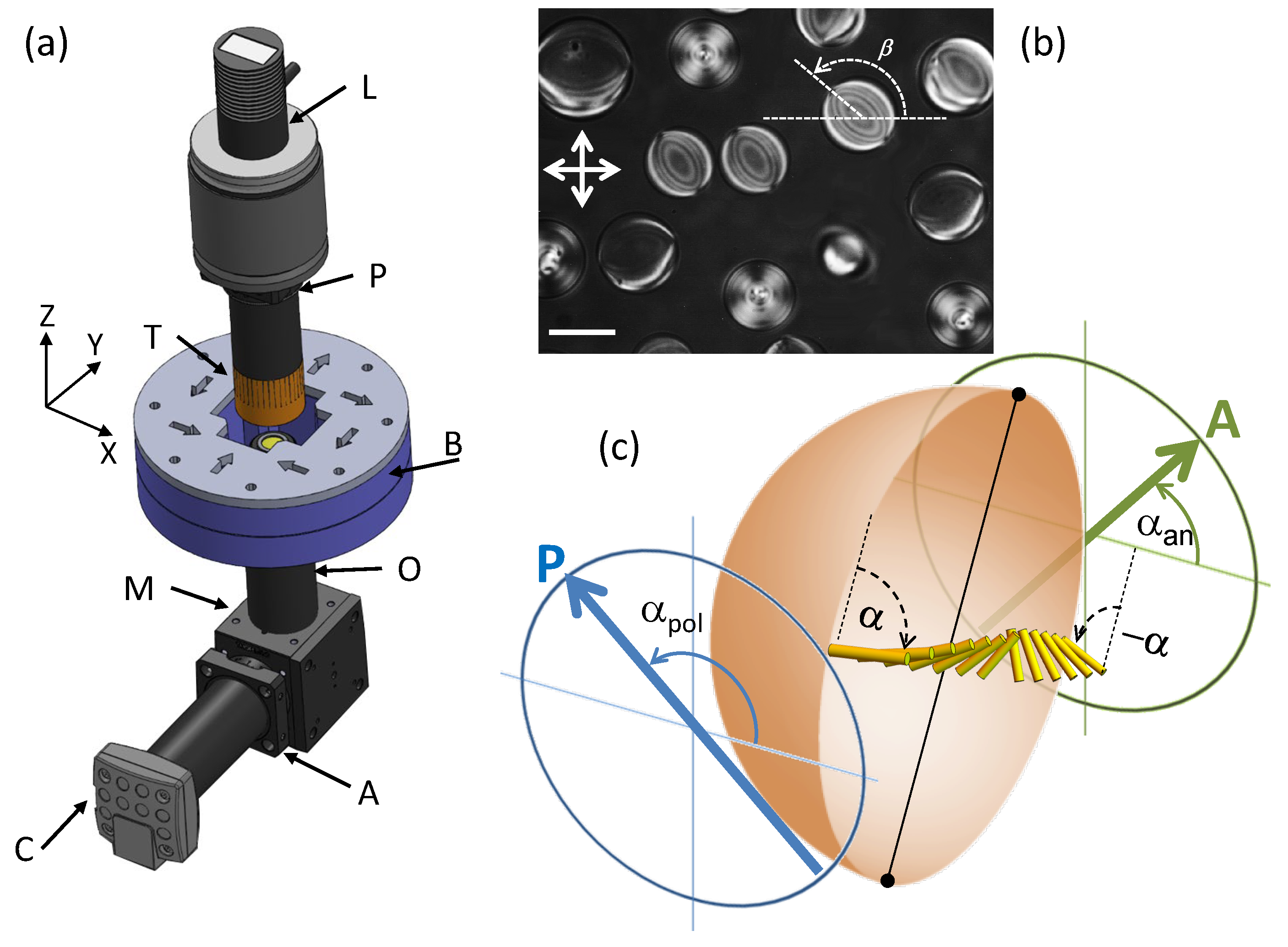
2.2. Observation and Control

Polarizing microscopy was carried out in a custom optical setup (Figure 1a), built to include a custom-made permanent magnet assembly that provided a homogeneous magnetic field perpendicular to the direction of light propagation, within a region much larger than the field of view, featuring a maximum strength of 0.4 T. The magnet was built using a Halbach cylindrical array [28] consisting on eight identical N52-grade Nd–Fe–B cubic magnets (cube size = 25.4 mm, K&J Magnetics). The magnets were assembled, with the suitable geometric arrangement, using a 3D-printed PLA enclosure (see Figure 1a and Ref. [29] for details). This is an extremely cost-effective setup to generate a magnetic field that is strong and homogeneous enough to align usual thermotropic mesogens, and also some lyotropic materials, such as SSY. The strength of the magnetic field was adjusted by modifying the vertical positioning of the sample with respect to the magnet plane. Both the orientation and the strength of the magnetic field where adjusted with motorized stages controlled using LabView. Samples were held inside a thermostatic oven (T) build with Thorlabs SM1 tube components and tape heater, and controlled with a Thorlabs TC200 device. The oven is held together with a 660 nm led light source (L, Thorlabs M660L2) and a polarizer (P). The observation module is placed in a three-axis translation stage and features an objective tube (O), an analyzer (A) and a camera (C). A mirror block (M) is used to increase the mechanical stability of the assembly.
Images of nematic droplets coexisting with the isotropic phase or dispersed in an isotropic oil (Figure 1b) were captured with a uEye monochrome CCD camera (Edmund Optics), driven with the public domain software Micro-Manager, built around the software ImageJ, which was also used for further image processing.

2.3. Image Analysis and Simulated Textures

The configuration of the director field inside a droplet is assessed by analyzing the light transmittance through the center of the droplet with different polarizer/analyzer configurations and a suitable optical model, as described in Section 3.1. The relevant geometrical parameters are illustrated in Figure 1c.
In order to interpret the polarizing microscopy images and to validate hypotheses on the director field configuration, we simulated the optical patterns of the birefringent droplets when observed through crossed polarizers. For this purpose, we employed a usual strategy based on Jones matrices that allow to compute the transmission of polarized light across a slab of birefringent material [30,31]. In brief, we assume that, in the direction of light propagation (Z-axis), the droplets are optically equivalent to a sequence of thin homogeneous slabs, and the equivalent Jones matrix at a point in the XY plane is J = J N J N 1 J 2 J 1 , where J i = J ( n ( z i ) ) is the Jones matrix corresponding to the LC slab at position z i where the local director is n ( z i ) . Calculations are implemented in Mathematica and grayscale images with the resulting array of local normalized transmittances are generated to compare with experiments.

3. Results and Discussion

3.1. Structure of the Nematic Gems

Inside SSY cells, nematic gems coexist with the isotropic phase in a wide temperature range, which allows us to easily adjust the size of the suspended droplets by heating or cooling the sample. Only droplets with diameters well below the cell gap are studied, to ensure their spherical shape. The textures observed between crossed polarizers are consistent with the TB configuration (Figure 2a), also reported earlier for emulsified SSY droplets [19]. Removing the microscope polarizer clearly reveals the two surface defects that organize the director field and the absence of any additional singularities (Figure 2b). The observed textures are faithfully reproduced by determining the light transmittance through a droplet where the director is considered to feature the TB texture (Figure 2c,d). The presence of twist can be readily assessed by comparing with droplet textures with different values of the twist angle at the boundary (Figure S1). In the case of emulsions, optical analysis in earlier experiments by Jeong et al. [19] revealed that the director field was twisted about 114.8 ± 4.4 degrees with respect to the bipolar alignment at the droplet surface. Such configuration was attributed to a balance between the elastic constants and, in particular, to the relatively low value of the twist constant (reported values are K 1 = 4.3 pN, K 2 = 0.7 pN, and K 3 = 6.1 pN [24]). Clearly, the energy landscape at the nematic/oil and at the nematic/isotropic interface should be different, and we expect this to have an impact on the value of the equilibrium director field. We have, therefore, proceeded to measure the twist angle of the TB director field in the nematic gems. For a given gem, the value for the twist angle with respect to the bipolar configuration, α , is obtained by measuring the transmittance through the center of the droplet for different relative orientations of polarizer and analyzer. We assume that the director profile through the center of the gem is a twisted nematic, for which the transmittance reads [30]
T cos 2 ( 2 α θ ) + sin 2 Ξ sin 2 ( α + β ) sin 2 ( α θ β ) ,
with Ξ = 4 α 2 + Γ 2 and Γ = π d λ Δ n (see Figure 1c and Figure 3a for the definition of angular variables), where d is the droplet diameter and Δ n the birefringence of the nematic phase. This expression is an approximation, ignoring similar trigonometric terms that contain α / Ξ , which is less than 0.1 in our system, as a prefactor [19,30]. Equation (1) assumes that the director field is in the Maugin regime, for which the polarization of propagating light rotates following the twist of the director. This approximation requires that | Γ | 1 , which is largely satisfied for our system, where the typical droplet diameter is above 50 μ m, the wavelength of light is 660 nm, and the birefringence is around −0.07 [32]. The only unknown parameter in Equation (1) is α (besides the gain and offset that relate the digitized light intensity with the transmittance, and are estimated from the analysis of the isotropic region around the gems). Notice that α can be either positive or negative, since droplets of both handedness coexist. Following the protocol used in Ref. [19] for emulsified droplets, we chose the sign that maximizes the absolute value of α (Figure 3b). Moreover, we find that the transmittance through the droplets is strongly affected by the value of Δ n, which can be found in recent measurements performed with similar light wavelengths, at different temperatures and compositions, but only in the nematic phase [32]. Since our experiments are performed in nematic gems within the coexistence region, we cannot know Δ n beforehand with enough precision. Because of this, for each droplet, we have fitted our transmittance data assuming different Δ n values within a ± 10 % band around the value expected from data in [32], and we have chosen the values for Δ n that optimize the fit to our data. Among those, following the same criterion stated above, we have select the value for Δ n that maximizes | α | . During this analysis, it is also crucial to only study droplets that feature a symmetric optical pattern, ensuring that their axis is nearly parallel to the observation plane. Even small misalignments result in appreciable distortions of the droplet texture (Figure S2), whose analysis leads to meaningless estimations for the twist angle α . The result of our analysis of around 30 droplets yields an estimation α = 102 ± 7 degrees, which is lower than the value found for emulsified SSY nematic gems. Although the difference between the two values is significant, it seems clear that the equilibrium twist angle in nematic SSY droplets is mostly due to the bulk elastic properties of the material, with only a small influence from the nature of the interface.
In the analysis above, we have restricted our study to gems of similar diameters, minimizing any size effect on α . Unlike cholesteric liquid crystals, where the pitch of the twist is an intrinsic property of the material and, therefore, the value of α would very strongly depend on gem size, here we have not detected any meaningful trend in the size range 40–100 μ m in diameter. In spite of the small twist constant of this material, it is to be expected that α would decrease for small enough gems, but those are very difficult to analyse with precision. Using simulated images, we compare the textures of a relatively small gem that preserves the same value of α as larger ones, and the same small gem where α is decreased (Figure S3). We conclude that variations of less than 20% would not be immediately apparent, but they would be obvious when α was less than half of its value in large gems. In our experiments, not even the smallest gems exhibit a texture similar to Figure S2e.

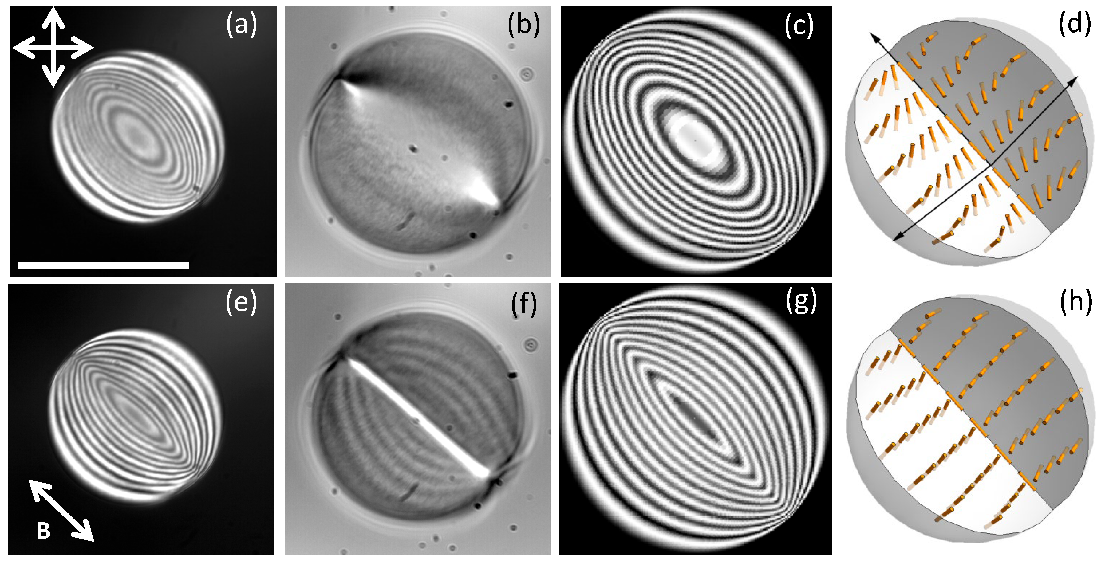
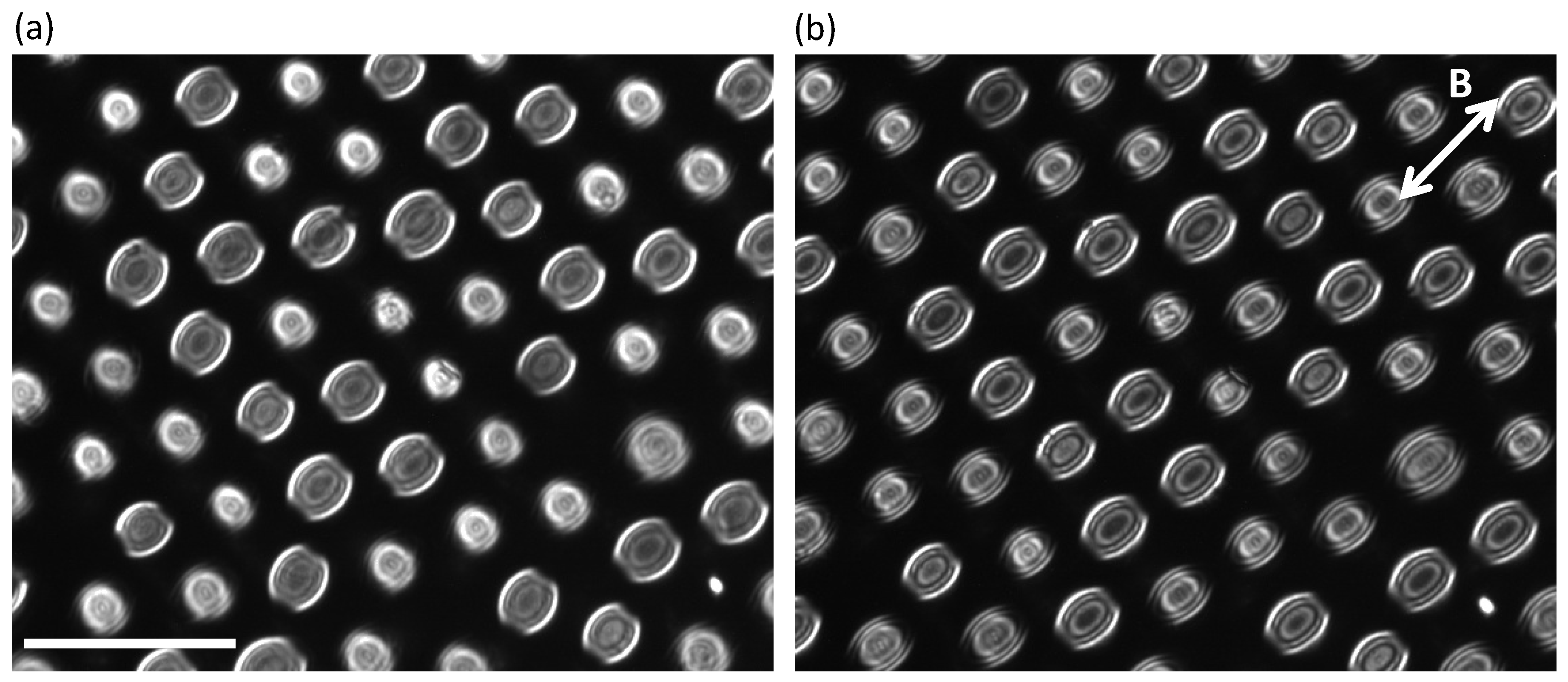
3.2. Nematic Gems in a Static Magnetic Field

One of the interesting features of this LCLC is its relatively large negative diamagnetic anisotropy [24], which allows us to align the director within suspended gems with modest magnetic fields (a few tenths of Tesla), easily attainable with permanent-magnet assemblies (Figure 1). In the case of thermotropic nematic gems, which typically feature a simple (untwisted) bipolar configuration (BC) of the director, application of our magnetic field leads to a reorientation of the gems so that their symmetry axis lays in the XY plane, and becomes perpendicular to B for negative diamagnetic anisotropy (Figure S4a,b), without significant changes in inner gem configuration. When a similar protocol is applied to the nematic SSY gems, we obtain two unexpected outcomes: on the one hand, the symmetry axis orients parallel to B rather than perpendicular to it; on the other hand, there is a significant texture change with respect to the unperturbed TB configuration (Figure S4c–e).
The new texture within the aligned SSY gems is studied in Figure 2, where observations are provided between crossed polarizers (Figure 2e) and without polarizer (Figure 2f). While changes with respect to the original TB configuration are apparent in all cases, Figure 2f reveals the formation of a disclination line along the symmetry axis. Taking into account that the director field aligns perpendicularly to B for this material, these observations are consistent with a concentric arrangement of the director, which organizes in circles perpendicular to B , leading to the formation of a disclination of strength +1 parallel to B . Similarly to what we have done to analyze TB textures, we have computed the simulated light transmittance through a droplet with the concentric configuration (CC) between crossed polarizers, obtaining a satisfactory agreement with the experimental images (Figure 2g,h). Bulk integer disclinations are unstable in equilibrium nematic liquid crystals, and have typically a escaped (three-dimensional) configuration that removes the singularity [7]. In our case, however, magnetic forcing is responsible for the stability of the disclination. Interestingly, this texture is reminiscent of the one observed when SSY gems transit from the nematic to the columnar phase in emulsified droplets [19]. In the latter case, the orientational order of the director is analogous to that in the CC, leading to a similar perception under crossed polarizers, but with a much slender singularity, suggesting that, in the case of nematic droplets aligned by a magnetic field, disclinations are always nonsingular. The formation of the CC in our system in the presence of a magnetic field can be understood by considering the equilibrium texture in the absence of an external field for this material with negative diamagnetic anisotropy. In the outer region of the gems, the director field is nearly perpendicular to the droplet axis, so the arrangement is close to concentric and far from bipolar in that region. Progressive application of the magnetic field leads to the reorientation of outer layers first, since they are less bound by elastic constraints. As the outer region becomes oriented perpendicular to B , the CC propagates towards the center of the droplet for higher fields (Figure S4). Notice that, since K 3 > K 1 in this material [24], the CC, where bend distortion dominates, has higher elastic energy than the BC, where splay dominates. Therefore, the organization into the higher energy CC by the magnetic field must be attributed to the presence of twist in the initial texture, unlike in ordinary thermotropic LCs, where the absence of twist prevents the concentric magnetic field alignment (Figure S4).

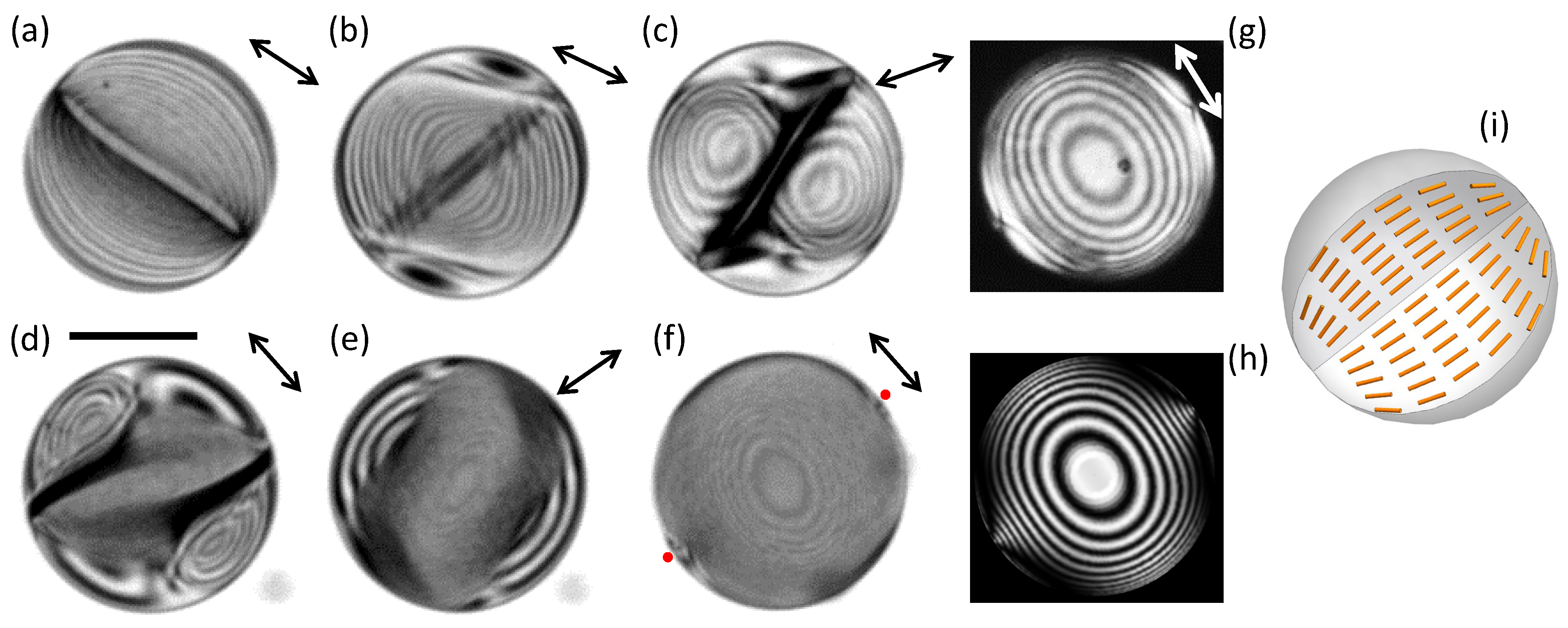
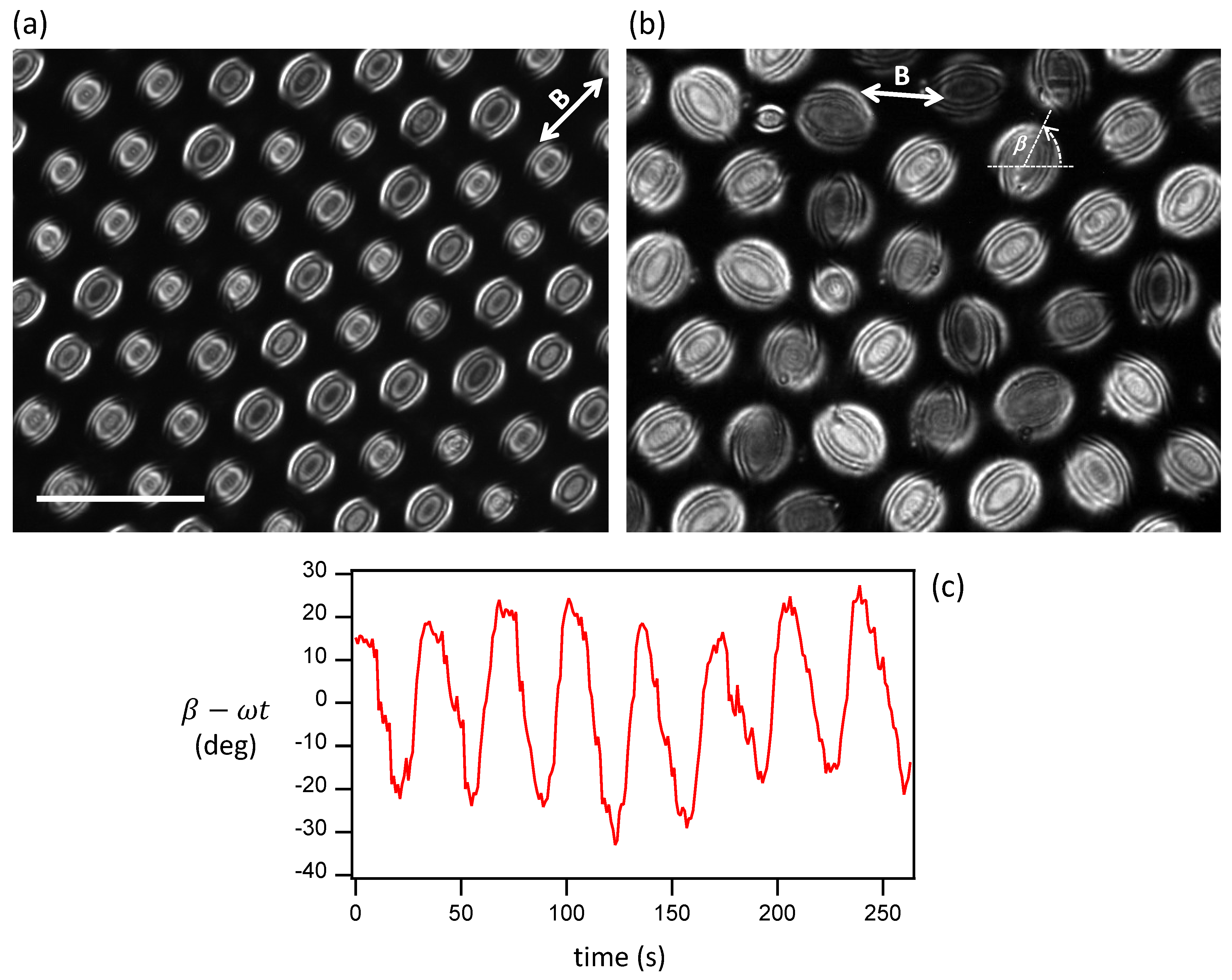
3.3. Transition to Bipolar Nematic Gems Under a Rotating Magnetic Field

In this section, we will drive the nematic gems by continuous rotation of the in-plane magnetic field. It is known that equilibrium nematic director fields can be driven into different, often metastable, configurations by imposing dynamic conditions, such as flow [17,33] or rotating fields [34]. When we rotate B at small rates (less than 1 deg s 1 ) the concentric configuration (Figure 2e) rotates continuously without any apparent distortion. Rotation of the director field requires to overcome the torque due to the rotational viscosity, which is achieved thanks to the magnetic torque that arises when the director field is misaligned from its equilibrium direction with respect to B . This misalignment is small at low rotation speeds, and can be used to determine the rotational viscosity in extended nematic phases [35]. When the rotation speed is increased (the experiment in Figure 4 is performed at 5 deg s 1 ), the misalignment increases, which is made apparent by the orientation of the disclination in the concentric configuration progressively losing its parallelism with B (Figure 4a,b). As the rotation continues, the misaligned concentric texture becomes unstable (Figure 4b), and the director field reorganizes completely, beginning from the boundary and proceeding inwards (Figure 4c–e) until a steady state configuration is attained, characterized by two surface defects at the poles perpendicular to B without the original disclination, which has vanished (Figure 4f). One particular dynamical feature of this new texture is its ability to rotate at the same pace as B , even when concentric droplets were lagging behind. Inspection between crossed polarizers (Figure 4g), and comparison with simulated textures (Figure 4h) reveals that it is an untwisted bipolar configuration oriented perpendicularly to B , analogous to the one observed for thermotropic LCs (Figure S4). The onset of this instability takes place at lower rotation speeds for larger nematic gems, with smaller concentric droplets being able to rotate faster. If the rotation is stopped and B is maintained at a constant intensity, gems with concentric and bipolar textures coexist, both structures being stable.
When the magnetic field is removed, all the gems relax towards the TB configuration, but gems that featured the CC director under magnetic field (labelled 1 in Figure 5a,b) become orthogonally-oriented to gems that featured the BC director (labelled 2 in Figure 5a,b). If the magnetic field strength is subsequently ramped up again to 0.4 T in the same direction as in Figure 5a, the original aligned configurations are recovered. In other words, droplets with the TB texture oriented perpendicularly to B evolve towards the BC, while those parallel to B recover the CC (Figure 5c). However, if the director field is reoriented before being ramped up, all the droplets attain the CC, and the memory of the BC is lost. Finally, if the system is allowed to relax in the absence of a magnetic field for a few minutes, all the gems regain the same CC upon reapplication of B , in any orientation, and the memory of the BC is also lost. We have also tested whether the type of alignment depends on the relative orientation between the static B and the original TB texture. Our results show no dependence, obtaining the same aligned CC when we follow cycles where a static B is applied, removed, and reapplied at new orientations, and with different ramp rates. We, therefore, speculate that the formation of the two surface defects in the dynamically-aligned BC under rotating B leads to changes in the local aggregation of the SSY molecules [32] that determines the recovery of the BC when a static B is reapplied.

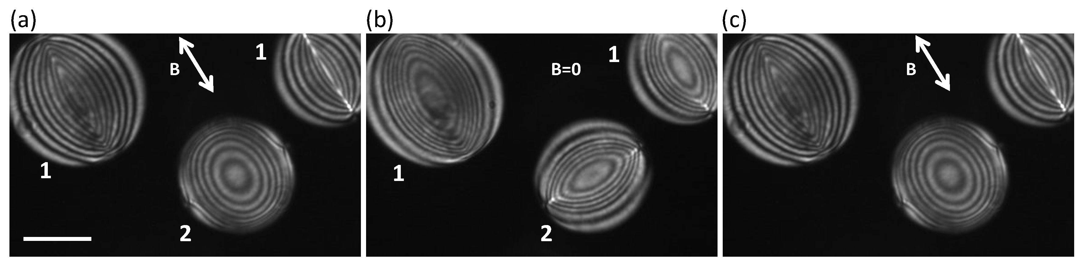
3.4. SSY Nematic Emulsions Under a Magnetic Field

In this last section, we extend the studies involving magnetic field control to emulsified nematic droplets. Earlier studies with SSY droplets suspended in hydrocarbon oils reported an unstable behavior, with droplets transiting to the columnar and to the solid phases due to their progressive drying as the water is absorved by the oil [19]. In our experience, this drying process is too fast to perform reliable studies with a magnetic field. In order to provide long-term stability of the nematic droplets and also to allow chemical compatibility with PDMS-based microfluidic devices, we have centered our efforts in the emulsification of SSY droplets in a fluorinated oil with suitable surfactants. The devices are built to include an observation chamber whose height allows droplets to remain spherical rather than flattened, and enables direct placement of the confined emulsions within the magnetic field (see Section 2).
Upon preparation, emulsified SSY droplets feature the TB texture analogous to the one reported with hydrocarbon oils [19], and similar to the one we have described for nematic gems. The main axes of the textures are randomly oriented, with some lying close to the plane of observation while others being close to perpendicular to it. Interestingly, the system features a droplet–droplet long range repulsion, presumably from electrostatic origin, that promotes the formation of an ordered lattice with an equilibrium inter-droplet distance of about twice the droplet diameters (Figure 6a).
Application of the in-plane B leads to reorientation of the director field inside the droplets consistent with the formation of a concentric texture whose axis is parallel to B (Figure 6b), in analogy with what we observed with the nematic gems. The change in internal texture is less apparent than in the latter case, most likely due to the fact that the average size of the observed droplets is less than half the size of the analyzed nematic gems. We have subsequently tested the stability of the aligned textures upon rotation of the magnetic field, finding that the dynamics is remarkably different from the one found for the nematic gems (Section 3.3). The regime where aligned droplets rotate following B is achievable for higher rates than with the gems (Figure 7a) but this can be attributed, at least in part, to the smaller size of droplets. Notice that the viscosity of the fluorinated oil is adjusted to be similar to that of the SSY, thus ruling this out as a possible difference between the two systems. Eventually, for larger droplets or higher rates, simple rotation within the suspended droplets becomes unstable (Figure 7b). Differently from the nematic gems, here the texture is preserved, and the symmetry axis performs asynchronous oscillations around the orientation of the magnetic field (Figure 7c). The period of these oscillations is not the same for all droplets of a similar size range, resulting in the progressive randomization of their symmetry axes. This behavior is reminiscent of the asynchronous rotation reported within smectic-C monolayer domains driven by optical fields, where a single stable configuration is achievable [36]. In the case of rotating SSY nematic gems, we have seen that a metastable bipolar configuration is forced by fast rotating fields. Clearly, the bipolar configuration is not achievable for the emulsified SSY droplets, which should be attributed to the differences in interactions across the aqueous/oil interface. Indeed, the transformation between the concentric and the bipolar texture in nematic gems begins at the boundary, and proceeds inwards during steady rotation. Alterations in the surface energy landscape thus contribute to stabilize the concentric configuration even for fast rotating fields. A final consideration concerns the potential presence of backflows surrounding the rotating droplets, and whether we are observing a pure director field rotation, or rather a combination of the latter with solid-body rotation of the emulsified nematic. This discussion is often encountered in the liquid crystal literature when director field rotations are induced in confined topologies, and the interpretation of the observations is not always clear [37,38]. In the present case, we have resorted to seeding the oil phase with scattered microparticles, and we have not observed any signature of organized flows surrounding the forced droplets. Our conclusion, then, is that the rotating magnetic field induces a pure director field rotation, with ensuing backflow effects being negligible.

4. Conclusions

In this work, we have reported experiments in which the dynamic behavior of either nematic gems or emulsified nematic droplets of SSY is studied under rotating magnetic fields. The different nature of the phases in coexistence with the confined lyotropic nematic mesogen, namely, a hydrophobic oil and the isotropic phase of SSY, are responsible for different surface-energy landscapes. We have found that the equilibrium director field is only marginally different when comparing the two scenarios in the field-free twisted-bipolar texture, and apparently identical in the concentric director configuration when aligned by the external magnetic field. Remarkably, the difference between the two preparations becomes clear when gems and droplets are brought out of equilibrium with a rotating field. While a metastable, untwisted bipolar texture emerges for the nematic gems and is able to rotate at faster speeds, the concentric arrangement remains stable for the emulsified nematic droplets, performing asynchronous oscillations about the instantaneous magnetic field orientation and preserving their integrity for fast rotating fields.
Our studies present a rare example of a metastable texture in nematic droplets driven by external forcing, and may be useful to understand the interplay between bulk elasticity and surface anchoring to determine the overall configuration. When involving emulsified nematic droplets, our protocol may be used to prepare ordered lattices of identical crystallites that may be obtained by the controlled drying of the aqueous-based mesogen, paving the way for the development of functional materials based on colloidal assemblies.

Supplementary Materials

The following are available online at https://www.mdpi.com/2073-4352/10/2/138/s1.

Author Contributions

Conceptualization, J.I.-M. and F.S.; investigation, M.M., B.M.-P., I.V.-C., R.S.H.; writing—original draft preparation, J.I.-M.; writing—review and editing, all authors. All authors have read and agreed to the published version of the manuscript.

Funding

This research was funded by Ministerio de Economía, Industria y Competitividad, Spain (projects FIS 2013-41144P and FIS2016-78507-C2-1-P, Agencia Estatal de Investigación/European Regional Development Fund).

Conflicts of Interest

The authors declare no conflict of interest.

References

  1. Oswald, P.; Pieranski, P. Nematic and Cholesteric Liquid Crystals: Concepts and Physical Properties Illustrated by Experiments; The Liquid Crystals Book Series; Taylor & Francis: Boca Raton, FL, USA, 2005. [Google Scholar]
  2. Kléman, M.; Lavrentovich, O.D. Soft Matter Physics: An Introduction; Partially Ordered Systems; Springer: New York, NY, USA, 2003. [Google Scholar]
  3. Kleman, M. Defects in liquid crystals. Rep. Prog. Phys. 1989, 52, 555–654. [Google Scholar] [CrossRef]
  4. Smalyukh, I.I. Liquid Crystal Colloids. Annu. Rev. Condens. Matter Phys. 2017, 9, 207–226. [Google Scholar] [CrossRef]
  5. Tai, J.S.B.; Smalyukh, I.I. Three-dimensional crystals of adaptive knots. Science 2019, 365, 1449–1453. [Google Scholar] [CrossRef] [PubMed] [Green Version]
  6. Senyuk, B.; Liu, Q.; He, S.; Kamien, R.D.; Kusner, R.B.; Lubensky, T.C.; Smalyukh, I. Topological colloids. Nature 2013, 493, 200–205. [Google Scholar] [CrossRef] [PubMed] [Green Version]
  7. Lopez-Leon, T.; Fernandez-Nieves, A. Drops and shells of liquid crystal. Colloid Polym. Sci. 2011, 289, 345–359. [Google Scholar] [CrossRef]
  8. Mondiot, F.; Wang, X.; de Pablo, J.J.; Abbott, N.L. Liquid crystal-based emulsions for synthesis of spherical and non-spherical particles with chemical patches. J. Am. Chem. Soc. 2013, 135, 9972–9975. [Google Scholar] [CrossRef] [PubMed] [Green Version]
  9. Musevic, I. Liquid Crystal Colloids. In Soft and Biological Matter; Springer Nature: Cham, Switzerland, 2017. [Google Scholar]
  10. Ondris-Crawford, R.; Boyko, E.P.; Wagner, B.G.; Erdmann, J.H.; Žumer, S.; Doane, J.W. Microscope textures of nematic droplets in polymer dispersed liquid crystals. J. Appl. Phys. 1991, 69, 6380–6386. [Google Scholar] [CrossRef]
  11. Miller, D.S.; Wang, X.; Abbott, N.L. Design of Functional Materials based on Liquid Crystalline Droplets. Chem. Mater. 2014, 26, 496–506. [Google Scholar] [CrossRef] [Green Version]
  12. Hakemi, H. Polymer-dispersed liquid crystal technology ‘industrial evolution and current market situation’. Liq. Cryst. Today 2017, 26, 70–73. [Google Scholar] [CrossRef]
  13. Sivakumar, S.; Wark, K.L.; Gupta, J.K.; Abbott, N.L.; Caruso, F. Liquid Crystal Emulsions as the Basis of Biological Sensors for the Optical Detection of Bacteria and Viruses. Adv. Funct. Mater. 2009, 19, 2260–2265. [Google Scholar] [CrossRef]
  14. Manna, U.; Zayas-Gonzalez, Y.M.; Carlton, R.J.; Caruso, F.; Abbott, N.L.; Lynn, D.M. Liquid crystal chemical sensors that cells can wear. Angew. Chem. Int. Ed. Engl. 2013, 52, 14011–14015. [Google Scholar] [CrossRef] [PubMed]
  15. Tone, C.M.; De Santo, M.P.; Buonomenna, M.G.; Golemme, G.; Ciuchi, F. Dynamical homeotropic and planar alignments of chromonic liquid crystals. Soft Matter 2012, 8, 8478. [Google Scholar] [CrossRef]
  16. Jeong, J.; Han, G.; Johnson, A.T.; Collings, P.J.; Lubensky, T.C.; Yodh, A.G. Homeotropic alignment of lyotropic chromonic liquid crystals using noncovalent interactions. Langmuir 2014, 30, 2914–2920. [Google Scholar] [CrossRef]
  17. Fernández-Nieves, A.; Link, D.; Márquez, M.; Weitz, D. Topological Changes in Bipolar Nematic Droplets under Flow. Phys. Rev. Lett. 2007, 98, 087801. [Google Scholar] [CrossRef] [PubMed] [Green Version]
  18. Jiang, J.; Yang, D.K. Bipolar to toroidal configuration transition in liquid crystal droplets. Liq. Cryst. 2017, 45, 102–111. [Google Scholar] [CrossRef]
  19. Jeong, J.; Davidson, Z.S.; Collings, P.J.; Lubensky, T.C.; Yodh, A.G. Chiral symmetry breaking and surface faceting in chromonic liquid crystal droplets with giant elastic anisotropy. Proc. Natl. Acad. Sci. USA 2014, 111, 1742–1747. [Google Scholar] [CrossRef] [Green Version]
  20. Tam-Chang, S.W.; Huang, L. Chromonic liquid crystals: properties and applications as functional materials. Chem. Commun. (Camb.) 2008, 1957–1967. [Google Scholar] [CrossRef]
  21. Park, H.S.; Lavrentovich, O. Lyotropic Chromonic Liquid Crystals:Emerging Applications. In Liquid Crystals Beyond Displays: Chemistry, Physics, and Applications; Li, Q., Ed.; John Wiley & Sons, Inc.: Hoboken, NJ, USA, 2012; Chapter 14. [Google Scholar]
  22. Xu, F.; Crooker, P. Chiral nematic droplets with parallel surface anchoring. Phys. Rev. E 1997, 56, 6853–6860. [Google Scholar] [CrossRef]
  23. Drzaic, P.S. A case of mistaken identity: spontaneous formation of twisted bipolar droplets from achiral nematic materials. Liq. Cryst. 1999, 26, 623–627. [Google Scholar] [CrossRef]
  24. Zhou, S.; Nastishin, Y.; Omelchenko, M.; Tortora, L.; Nazarenko, V.; Boiko, O.; Ostapenko, T.; Hu, T.; Almasan, C.; Sprunt, S.; et al. Elasticity of Lyotropic Chromonic Liquid Crystals Probed by Director Reorientation in a Magnetic Field. Phys. Rev. Lett. 2012, 109, 037801. [Google Scholar] [CrossRef] [Green Version]
  25. Ignes-Mullol, J.; Poy, G.; Oswald, P. Continuous Rotation of Achiral Nematic Liquid Crystal Droplets Driven by Heat Flux. Phys. Rev. Lett. 2016, 117, 057801. [Google Scholar] [CrossRef] [PubMed] [Green Version]
  26. Park, H.S.; Kang, S.W.; Tortora, L.; Nastishin, Y.; Finotello, D.; Kumar, S.; Lavrentovich, O.D. Self-assembly of lyotropic chromonic liquid crystal Sunset Yellow and effects of ionic additives. J. Phys. Chem. B 2008, 112, 16307–16319. [Google Scholar] [CrossRef] [PubMed]
  27. Abate, A.R.; Weitz, D.A. Syringe-vacuum microfluidics: A portable technique to create monodisperse emulsions. Biomicrofluidics 2011, 5, 14107. [Google Scholar] [CrossRef] [Green Version]
  28. Soltner, H.; Blümler, P. Dipolar Halbach magnet stacks made from identically shaped permanent magnets for magnetic resonance. Concepts Magn. Reson. Part A 2010, 36A, 211–222. [Google Scholar] [CrossRef]
  29. Guillamat, P.; Ignes-Mullol, J.; Sagues, F. Control of active liquid crystals with a magnetic field. Proc. Natl. Acad. Sci. USA 2016, 113, 5498–5502. [Google Scholar] [CrossRef] [Green Version]
  30. Yeh, P.; Gu, C. Optics of Liquid Crystal Displays; Wiley Series in Pure And Applied Optics; Wiley: New York, NY, USA, 1999. [Google Scholar]
  31. Ellis, P.W.; Pairam, E.; Fernández-Nieves, A. Simulating optical polarizing microscopy textures using Jones calculus: A review exemplified with nematic liquid crystal tori. J. Phys. Appl. Phys. 2019, 52, 213001. [Google Scholar] [CrossRef]
  32. Horowitz, V.R.; Janowitz, L.A.; Modic, A.L.; Heiney, P.A.; Collings, P.J. Aggregation behavior and chromonic liquid crystal properties of an anionic monoazo dye. Phys. Rev. E 2005, 72, 041710. [Google Scholar] [CrossRef] [Green Version]
  33. Giomi, L.; Kos, Z.; Ravnik, M.; Sengupta, A. Cross-talk between topological defects in different fields revealed by nematic microfluidics. Proc. Natl. Acad. Sci. USA 2017, 114, E5771–E5777. [Google Scholar] [CrossRef] [Green Version]
  34. Xu, F.; Kitzerow, H.; Crooker, P.P. Electric-field effects on nematic droplets with negative dielectric anisotropy. Phys. Rev. A 1992, 46, 6535–6540. [Google Scholar] [CrossRef]
  35. Oswald, P. Easy axis memorization with active control of the azimuthal anchoring energy in nematic liquid crystals. EPL (Europhys. Lett.) 2014, 107, 26003. [Google Scholar] [CrossRef]
  36. Burriel, P.; Ignes-Mullol, J.; Reigada, R.; Sagues, F. Collective molecular precession induced by rotating illumination in photosensitive Langmuir monolayers. Langmuir 2006, 22, 187–193. [Google Scholar] [CrossRef] [PubMed]
  37. Yoshioka, J.; Ito, F.; Suzuki, Y.; Takahashi, H.; Takizawa, H.; Tabe, Y. Director/barycentric rotation in cholesteric droplets under temperature gradient. Soft Matter 2014, 10, 5869–5877. [Google Scholar] [CrossRef] [PubMed]
  38. Poy, G.; Oswald, P. Do Lehmann cholesteric droplets subjected to a temperature gradient rotate as rigid bodies? Soft Matter 2016, 12, 2604–2611. [Google Scholar] [CrossRef] [PubMed]
Figure 1. (a) Experimental setup. A homemade polarizing microscope is fitted with a permanent magnet array that imposes a magnetic field in the XY plane. (b) Typical ensemble of Sunset Yellow (SSY) nematic gems in coexistence with isotropic liquid as seen between crossed polarizers. The orientation of the symmetry axis of a gem with respect to the horizontal defines the angle β . (c) Geometrical parameters used in the analysis of the director field profile through the center of the gems. Scale bar is 100 μ m.
Crystals 10 00138 g001
Figure 2. SSY nematic gem in coexistence with its isotropic phase, in the absence (ad) and in the presence (eg) of a 0.4 T in-plane uniform magnetic field, as indicated in panel (e) (see also Movie 1 and Movie 2 for textural changes during the ramping up of the magnetic field). Optical micrographs with crossed polarizers (a,e) and without polarizer (b,f) are shown. Simulated textures corresponding to (a) and (e) are shown in (c) and (g), respectively, obtained by computing the transmittance between crossed polarizers of the director field configurations sketched in (d,h). Scale bar is 100 μ m.
Crystals 10 00138 g002
Figure 3. (a) Definition of angular variables involved in the analysis of light transmittance through the liquid crystal. All angles are referred to the orientation of the director field where light enters the sample. (b) Transmittance data through the center of a SSY nematic gem in coexistence with the isotropic medium as a function of the angle between analyzer and polarizer when the latter is rotated continuously. The solid line is a fit to the function described in the text for a twisted bipolar director field.
Crystals 10 00138 g003
Figure 4. (af) Transition of a SSY nematic gem from the concentric to the bipolar configuration under a 0.4 T magnetic field that is rotating counterclock-wise at 5 deg s 1 (see also Movie 3). The instantaneous orientation of the magnetic fields is sketched in each panel. For clarity, micrographs are taken without polarizers. Elapsed times from frame (a) are 110 s (b), 191 s (c), 224 s (d), 241 s (e), and 373 s (f). Red dots in panel (f) mark the position of the two surface defects. (g) Final bipolar configuration observed between crossed polarizers. (h) Computed transmittance corresponding the director field sketched in (i) that matches the experimental pattern in (g). Scale bar is 100 μ m.
Crystals 10 00138 g004
Figure 5. (a) Concentric (1) and bipolar (2) SSY nematic gems coexisting under a static 0.4 T magnetic field that had been previously rotated at 5 deg s 1 . (b) The magnetic field is removed, leading to twisted bipolar configurations, with the two types of gems observed in (a) oriented orthogonaly to each other. (c) Upon quick re-application of the 0.4 T field, the same original textures obtained in (a) are recovered, illustrating a memory of the bipolar texture. Scale bar is 50 μ m.
Crystals 10 00138 g005
Figure 6. (a) SSY nematic droplet assembly suspended in fluorinated oil inside a chamber of height 125 μ m. (b) The assembly is placed inside a 0.4 T magnetic field resulting in a reorientation of the nematic droplets. Scale bar is 100 μ m.
Crystals 10 00138 g006
Figure 7. Emulsified SSY droplets during magnetic field rotation at 10 deg s 1 (a) and 7.2 deg s 1 (b). While small droplets are able to follow the rotation rate (a, and Movie 4) larger droplets lag behind, and feature asynchronous oscillations (b and Movie 5). The instantaneous orientation of the rotating field is overlaid on each image. Scale bar is 100 μ m. (c) Oscillation of the orientation of the droplet axis, β , with respect to the rotation angle, ω t , for a sample droplet, where ω is the angular velocity.
Crystals 10 00138 g007

