Article

Fast-Response Liquid Crystal Phase Modulators with an Excellent Photostability

College of Optics and Photonics, University of Central Florida, Orlando, FL 32816, USA
*
Author to whom correspondence should be addressed.
Crystals 2020, 10(9), 765; https://doi.org/10.3390/cryst10090765
Submission received: 20 August 2020 / Revised: 26 August 2020 / Accepted: 28 August 2020 / Published: 29 August 2020
(This article belongs to the Special Issue Patterned-Liquid-Crystal for Novel Displays)

Abstract

:
We report a new mixture, which is modified from Merck TL-216, for liquid-crystal-on-silicon spatial light modulators (SLMs). To achieve 2π phase change at λ = 633 nm with 5 V operation voltage, the measured response time is about 3 ms at 50 °C. Meanwhile, our mixture exhibits no sign of photodegradation and even the total dosage has exceeded 400 MJ/cm2 at a blue laser wavelength λ = 465 nm. In comparison, E7 died at about 30 MJ/cm2. Widespread applications of this material for high brightness SLMs, near-eye displays, and head-up displays are foreseeable.

1. Introduction

Liquid crystals (LCs) have been widely used in display devices [1,2], such as augmented reality (AR) and virtual reality (VR) [3], tablets, computers, TVs, vehicle displays, and data projectors, to name a few. For amplitude modulation, the required phase retardation (δ = 2πdΔn/λ) is about 1π, depending on the LC mode employed [4], where d is the cell gap, Δn is the LC birefringence, and λ is the wavelength. For display applications, the central wavelength is λ = 550 nm and the cell gap is controlled at 3 μm in order to obtain fast response time and high manufacturing yield. Under such conditions, the required Δn is approximately 0.1. For such a low Δn LC material, fluorinated cyclohexane-phenyl compounds [5,6,7] are commonly used. These compounds exhibit low viscosity, high resistivity, and excellent photostability.
On the other hand, phase-only liquid-crystal-on-silicon (LCoS) panels [8,9,10] have also found widespread application in adaptive optics for wavefront corrections [11], beam shaping for lithography [12], telecom as a wavelength selective switch [13], and multifocal displays [14,15,16] for overcoming the vergence-accommodation conflict issue in AR and head-up displays [17]. For such a spatial light modulator (SLM), the required phase change is and the response time should be less than 4 ms to support the desired 240 Hz frame rate. From the focal surface displays [18,19], both Oculus and Microsoft SLMs are operated at 60 Hz, which is four times too slow to meet the desired 240 Hz. Therefore, there is an urgent need to develop a phase-only LCoS SLM with response time (τ) less than 4 ms, while keeping a phase change, low operation voltage (≤5 Vrms, the root-mean-square voltage) without the overdrive and undershoot driving circuitry, and excellent photostability, especially in the blue spectral region.
To achieve fast response time while keeping a low operating voltage, a straightforward method is to reduce the cell gap. LCoS is a reflective device, which means the incident light traverses the LC layer twice [20]. For example, to achieve phase change at λ = 633 nm using a 1.5 μm cell gap, the required Δn is 0.211. Moreover, the actual operating temperature of LCoS is 40–50 °C due to the thermal effects from the CMOS (complementary metal–oxide–semiconductor) backplane and high-power light source [21]. As the temperature increases, both viscoelastic constant and birefringence decrease but at different rates [22]. The former helps to achieve fast response time, but the latter demands a slightly thicker cell gap or a higher birefringence at the room temperature. In the meantime, photostability of the employed high Δn LC materials and alignment layers is essential for extending the SLM lifetime [23,24]. LCoS projection displays are usually illuminated by a relatively high-power arc lamp, light emitting diodes, or lasers. Even if the ultraviolet and infrared parts of the arc lamp light source are filtered out, the remaining blue light may still degrade the device lifetime. These high-energy photons could decompose the LC compounds or deteriorate the polyimide alignment layer, which in turn changes the pretilt angle of the LC and consequently affects the electro-optic properties. Inorganic SiOx alignment layers [25] have been found to sustain long-term UV and blue light exposure without damage [26], but the photostability of high Δn LC materials, especially in the blue spectral region, have not been investigated thoroughly.
In this paper, we report a new LC mixture optimized for the LCoS SLMs. Its modest birefringence and low viscoelastic constant jointly contribute to fast response time (~3.14 ms @ 50 °C) and its stable chemical structure exhibits an excellent photostability at λ = 465 nm for a dosage over 400 MJ/cm2.

2. LC Mixture Formulation

We have evaluated several commercial high birefringence LC mixtures, including E7 and Merck TL-213 and TL-216. Among them, TL-216 exhibits an excellent photostability at λ = 465 nm. However, as will be shown later, its response time falls short of our targeted 4 ms for 240 Hz operation. The response time of an LC material is proportional to the cell gap squared (d2). To keep the same 2π phase change for an LCoS, the most effective method is to reduce the cell gap by increasing LC birefringence. Therefore, our strategy is to dope Merck TL-216 with a high Δn, large dielectric anisotropy (Δε) and low-viscosity trifluoro-terphenyl compound (abbreviated as PPP-3FFF), whose molecular structure is shown in Figure 1.
The melting temperature of PPP-3FFF is 118.7 °C and heat fusion anthalpy is 4039 cal/mol [27]. Although it does not have a nematic phase, in experiment we doped 15% and 20% PPP-3FFF into TL-216 and the mixtures remain liquid at 22 °C. The 20% mixture exhibits a slightly higher Δn and larger Δε than the 15% one. We named this mixture (80 wt.% TL-216 + 20 wt.% PPP-3FFF) as UCF-216 and use it for all the electro-optic and photostability studies reported here.

3. Material Characterizations

First, we characterize and compare the physical properties of TL-216 and UCF-216. Their phase transition temperatures and physical properties (at T = 22 °C) are summarized in Table 1. We measured the melting temperature (Tm) and clearing temperature (Tc) by differential scanning calorimetry (DSC, TA Instruments Q100). The wide nematic range (−20 °C ~ 80 °C) satisfies the requirement for most LCoS applications. We also measured the dielectric constants with a multifrequency LCR meter, HP-4274. The viscoelastic constant γ1/K11 of each mixture was measured from the free relaxation response time of a test cell. The relatively low γ1/K11 effectively helps to reduce the response time.

3.1. Birefringence

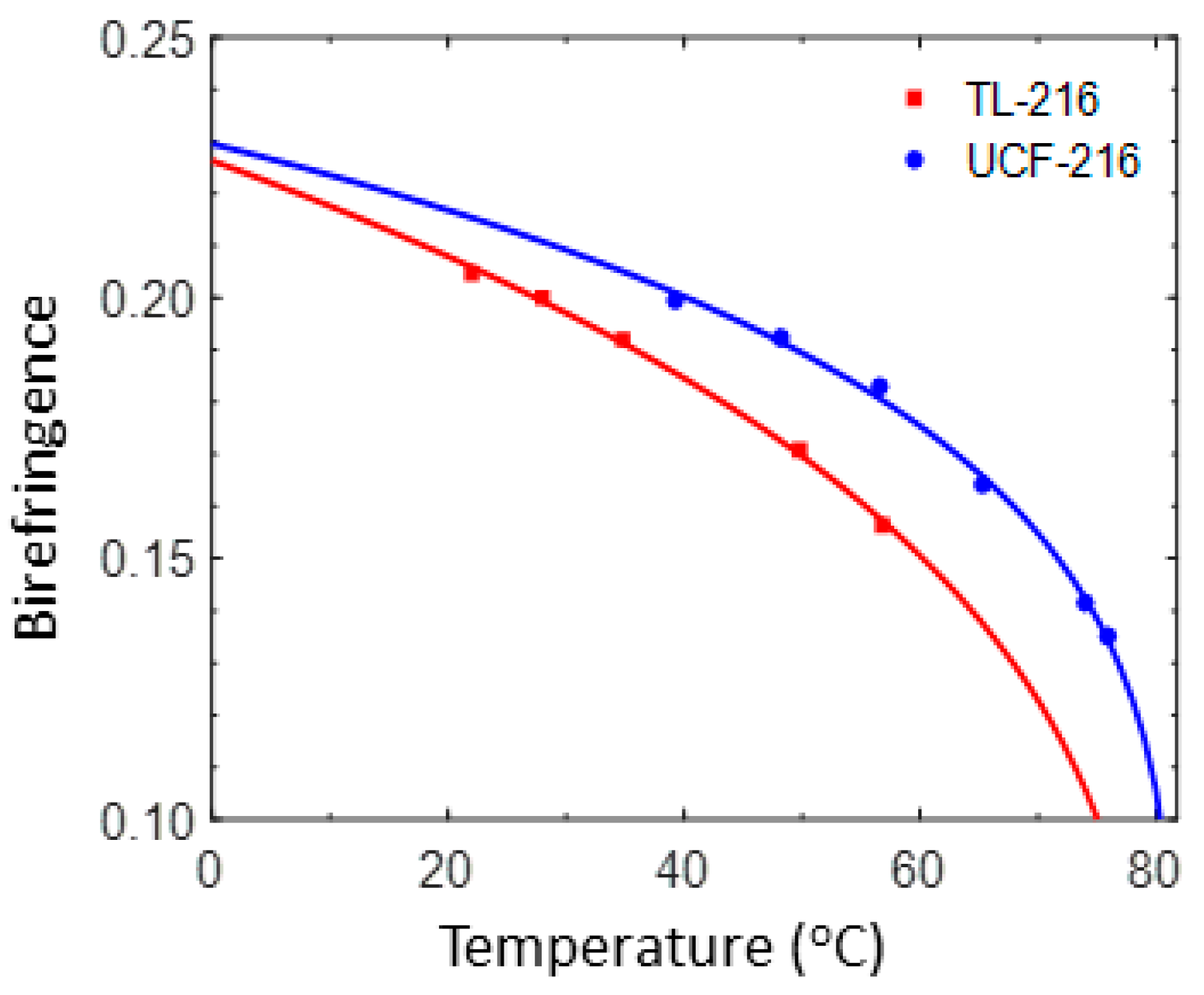
Birefringence determines the cell gap, which in turn affects the response time. To measure Δn, we filled each LC mixture into a homogeneous cell with cell gap d ≈ 5µm. The pretilt angle of the rubbed polyimide alignment layers is about 3°. We sandwiched each cell between crossed polarizers and activated it with a 1 kHz square-wave AC voltage. The sample temperature was controlled by a Linkam heating stage through a temperature programmer TMS94. The birefringence was calculated from the measured phase retardation. Figure 2 depicts the temperature-dependent birefringence at λ = 633 nm (He–Ne laser), where dots represent the measured data and solid lines represent the fitting with following equation [28,29]:
Δ n = Δ n 0 S = Δ n 0 ( 1 T / T c ) β .
In Equation (1), Δn0 stands for the extrapolated birefringence at T = 0 K, S is the order parameter, Tc (unit: K) is the clearing temperature of the LC, and exponent β is a material parameter. Both Δn0 and β can be obtained by fitting the experimental data with Equation (1). Results are listed in Table 2. For convenience, we use Celsius (°C) instead of Kelvin temperature (K) in Figure 2 and Figure 3.

3.2. Viscoelastic Constant

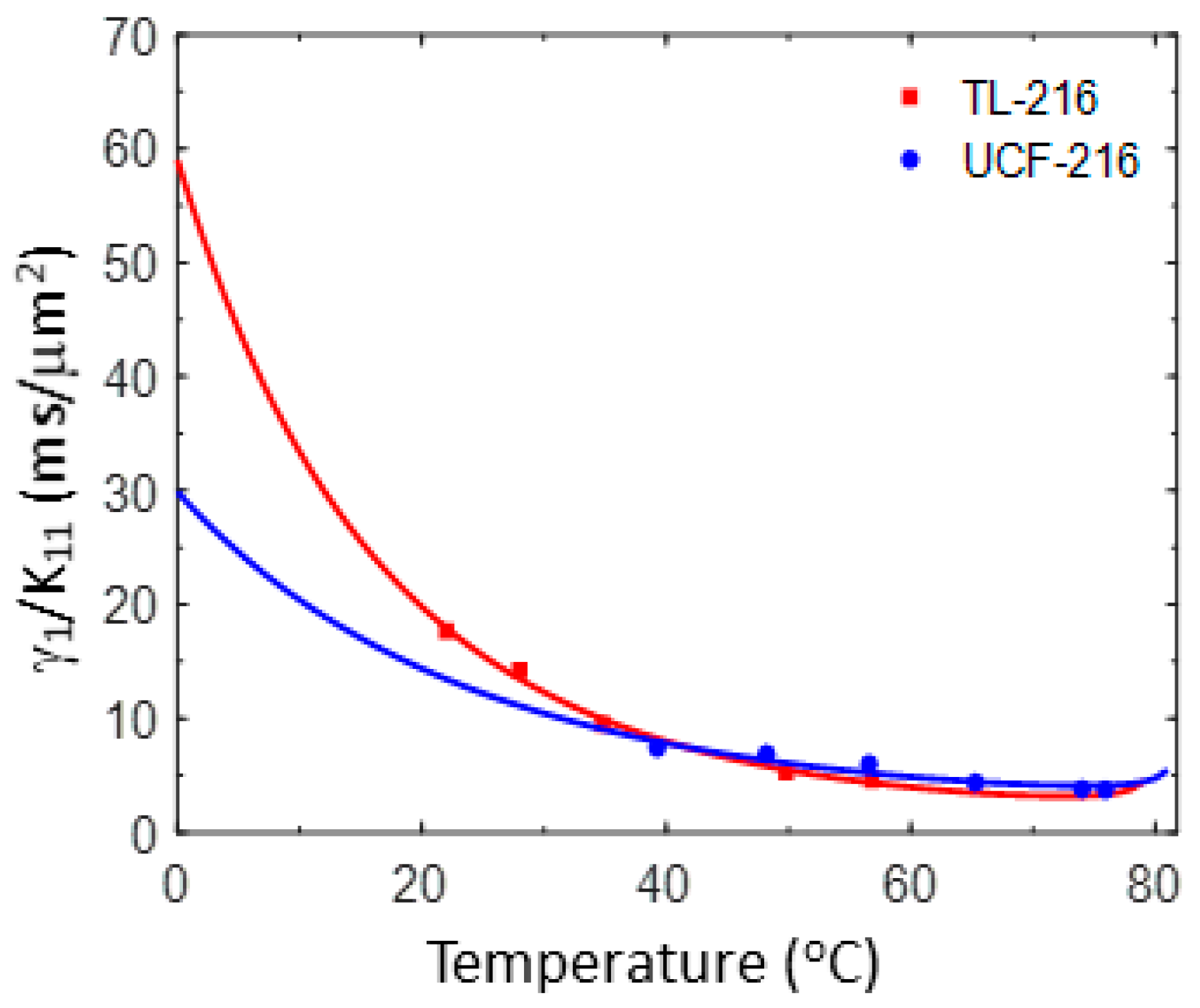
We also measured the transient decay time of these two LC materials and obtained the temperature-dependent viscoelastic constant γ1/K11, shown by the dots presented in Figure 3. The solid lines represent fittings with following equation [22]:
γ 1 K 11 = A exp ( E a / k B T ) ( 1 T / T c ) β .
In Equation (2), A, Ea, and KB stand for the proportionality constant, activation energy, and Boltzmann constant, respectively. The fitting parameters are also included in Table 2. From Figure 3 and Equation (2), we can see that γ1/K11 decreases dramatically as the temperature increases and then gradually saturates as the temperature approaches to the clearing point.

3.3. Voltage Dependent Phase Change

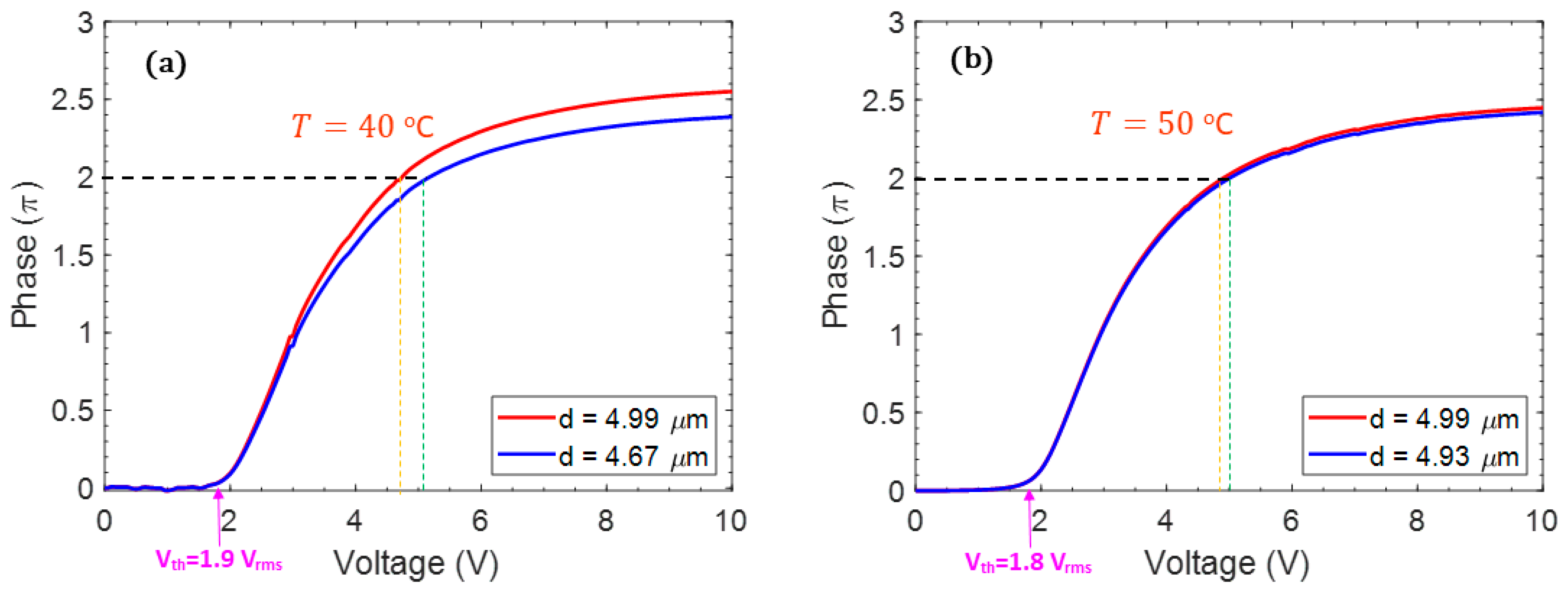
As mentioned above, for a working LCoS device, its operating temperature is about 40−50 °C due to the thermal effects of CMOS backplane and the high-power light source. Therefore, we focus our studies at two temperatures: 40 °C and 50 °C. The voltage-dependent phase (V-Φ) curves of these materials can be converted from the voltage-dependent transmittance (V-T) curve measured at λ = 633 nm. Figure 4a,b depicts the V-Φ curve of TL-216 (d = 4.99 μm) at 40 °C and 50 °C, respectively. Although the LCoS is a reflective device, our measurements were conducted in transmissive cells, because we did not have such a thin LC cell in our labs. Our measured results can be converted to the corresponding reflective cells easily. From Figure 4, the V2π of TL-216 occurs at 4.7 Vrms at 40 °C and 4.9 Vrms at 50 °C (red lines). To explain the slightly increased V2π, we have to consider two factors as the temperature increases: (1) decreased birefringence and (2) decreased threshold voltage (Vth). The former is more apparent than the latter, leading to a slightly higher V2π at 50 °C. It should be mentioned that our allowed V2π is 5 Vrms, that means we can use a slightly thinner cell gap to achieve the desired 2π phase change. The V-Φ curve of a different cell gap can be extrapolated by simply using the phase retardation equation δ = 2πdΔn/λ. If we operate TL-216 at 50 °C, we could use a slightly thinner cell gap (4.93 μm transmissive cell or 2.47 μm reflective LCoS) to obtain V2π at 5 Vrms, as the blue line shows. A thinner cell gap leads to a faster response time, which will be discussed quantitatively later.
Similar measurements and extrapolations apply to UCF-216 using a d = 5.01 μm transmissive cell at λ = 633 nm. Figure 5a,b shows the measured and extrapolated voltage-dependent phase change of UCF-216 at 40 °C and 50 °C. At 50 °C, as the red line shows, V2π occurs at 3 Vrms because of its higher Δn and lower threshold voltage (1.2 Vrms). Since our allowed V2π is 5 Vrms, we can reduce the cell gap to 4.14 μm, as the blue line indicates in Figure 5b. For reflective mode operation, this corresponds to d = 2.07 μm.

3.4. Response Time

The switching time (rise time and decay time) between two gray levels (V1 and V2) of an LC phase modulator are governed by the LC cell gap, viscoelastic constant, and operating voltages as [30]:
τ o n = τ 0 ( V 2 / V t h ) 2 1 ,
τ o f f = τ 0 | ( V 1 / V t h ) 2 1 | ,
τ 0 = γ 1 d 2 K 11 π 2 .
In Equations (3)–(5), Vth is the threshold voltage, V2 is the high gray-level voltage, V1 is the low gray-level voltage, and τ0 is the free relaxation time, i.e., V1 = 0. From Equations (3) and (4), the response time near Vth is sluggish. In Figure 5b, at 50 °C, because V2π of UCF-216 with cell gap d = 5.01 μm is not too far from the threshold voltage (Vth = 1.2 Vrms), according to Equation (3) the rise time will be slow. From our previous studies [31,32], the average gray-to-gray rise time and decay time is about the same as the sum of turn-on time (V2 = 8th gray level; in our case 5 V) and free relaxation time (V1 = 0).
We then measured the rise time and decay time of TL-216 and UCF-216 at two different temperatures and converted these data into reflective cells. Table 3 summarizes the measured response time of TL-216, using a d = 4.99 μm transmissive cell at λ = 633 nm and T = 40 °C and 50 °C. From Table 3, TL-216 can achieve 12 ms at T = 40 oC with V2π = 4.7 Vrms, and 6.9 ms at 50 °C with V2π = 4.9 Vrms. If we operate TL-216 at 50 °C with a cell gap of 4.93 μm transmissive cell to satisfy V2π = 5 Vrms, the total response time τon + τoff = 6.7 ms, which is about 1.6× slower than the desired 4 ms.
Table 3 summarizes the measured response time of UCF-216, using a d = 5.01 μm test cell at λ = 633 nm and T = 40 °C and 50 °C. From Table 4, UCF-216 can achieve 10.06 ms at T = 40 °C with V2π = 2.93 Vrms, and 6.48 ms at 50 °C with V2π = 3.0 Vrms. It should be mentioned that our allowed V2π is 5 Vrms. If we operate UCF-216 at 50 °C, we can use a slightly thinner cell gap (4.14 μm in transmissive mode or 2.07 μm in reflective LCoS @ 50 °C) to increase V2π to 5 Vrms. Under such condition, the rise time can be reduced. From Table 4, the total response time τon + τoff = 3.14 ms, which enables LCoS SLM to be operated at ~300 Hz.

3.5. Photostability

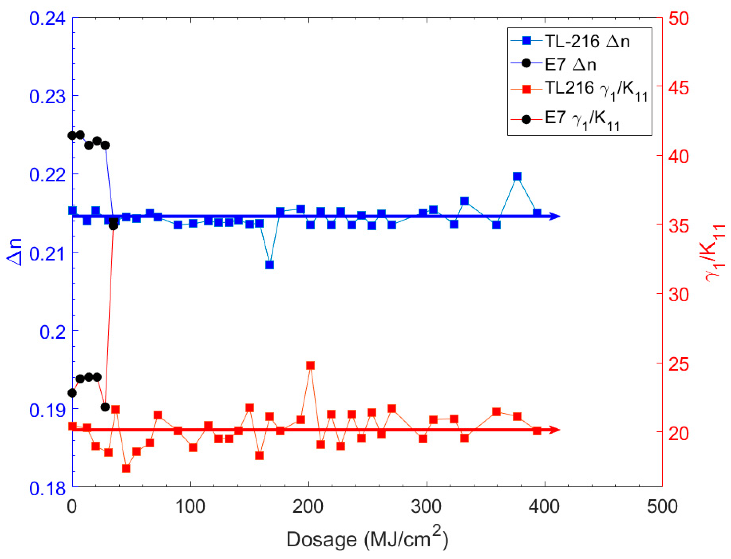
To investigate the photostability of TL-216 and UCF-216, we prepared the test cells using indium tin oxide (ITO)–glass substrates overcoated with a thin inorganic SiOx alignment layer. In experiment, we injected TL-216 into a 9-µm-thick homogeneous cell with SiOx alignment layers. To perform an accelerated photostability test, we employed a high-power CW blue diode laser with λ = 465 nm. The peak power was 9 W, and the laser intensity was kept at 200 W/cm2. We exposed the test cell for one day and then took it out from the exposure system for about 30 min to measure its birefringence (blue circles) and viscoelastic constant (red squares). After the measurements, we put the sample back to the irradiation system for further exposure. The measured results are recorded in Figure 6. As the dosage increased, Δn and γ1/K11 remain basically unchanged. We also measured the photostability of UCF-216 and the results are as stable as TL-216 shown in Figure 6 because our fluorinated terphenyl compound has an excellent photostability at λ = 465 nm. From Figure 6, both TL-216 and UCF-216 show no sign of degradation even though the total dosage exceeded 400 MJ/cm2.
Based on Merck’s publications [33,34] and judging from its birefringence, the major compositions of TL 216 are likely to be chlorinated and fluorinated terphenyls. These compounds offer a modest birefringence (Δn ≈ 0.21) and dielectric anisotropy (Δε ≈ 5), and more importantly, excellent photostability in the blue wavelength.
Included in Figure 6 are the photostability data of E7, which consists of 92% cyano-biphenyl (51% 5CB, 25% 7CB and 16% 8OCB) and 8% cyano-terphenyl (5CT) compounds. To our surprise, E7 was degraded after 30 MJ/cm2, which implies 5CT is not stable enough under blue light irradiation. From the polarized absorption spectra of 5CT [35], the longest π→π* transition band occurs at 306 nm and the tail diminishes when λ > 400 nm. We also measured the transmission spectrum of a 9 μm E7 cell in the UV–visible region and did not find any noticeable absorption at λ = 465 nm.
We inspected the damaged patterns of the E7 cell under a white light table between two crossed polarizers. Figure 7 shows the photo. The deteriorated part turns to black between crossed polarizers. This implies that the LC material changed from homogeneous alignment to vertical alignment after degradation. Next, we applied a voltage to the test cell and found the damaged area is no longer switchable, which further confirms its vertical alignment. Although the detailed degradation mechanism of E7 is still under investigation, these data shed important insight for tailoring fast-response LC phase modulators while keeping an excellent photostability.

4. Conclusions

In conclusion, we have developed a new LC mixture, designated as UCF-216, which is suitable for high brightness LCoS SLMs. The mixture exhibits fast response time (~3.14ms @ 50 °C), low operation voltage (5 V), and excellent photostability. Under a blue laser (λ = 465 nm) illumination, UCF-216 shows no sign of degradation, even when the accumulated dosage exceeds 400 MJ/cm2. In comparison, E7 died at about 30 MJ/cm2 under the same exposure conditions. Practical applications of UCF-216 for laser-based SLMs, high brightness AR displays, and head-up displays are foreseeable.

Author Contributions

Methodology, Q.Y., J.Z. and Y.L.; writing—original draft preparation, Q.Y.; writing—review and editing, S.-T.W.; supervision, S.-T.W. All authors have read and agreed to the published version of the manuscript.

Funding

Sony Corporation.

Acknowledgments

The UCF group is indebted to Sony Corp. for the financial support, and Akiko Toriyama and Koichi Nagasawa for technical collaboration and useful discussion.

Conflicts of Interest

The authors declare no conflict of interest.

References

  1. Schadt, M. Milestone in the History of Field-Effect Liquid Crystal Displays and Materials. Jpn. J. Appl. Phys. 2009, 48, 03B001. [Google Scholar] [CrossRef]
  2. Huang, Y.; Hsiang, E.L.; Deng, M.Y.; Wu, S.T. Mini-LED, Micro-LED and OLED displays: Present status and future perspectives. Light Sci. Appl. 2020, 9, 105. [Google Scholar] [CrossRef]
  3. Zhan, T.; Yin, K.; Xiong, J.; He, Z.; Wu, S.T. Augmented reality and virtual reality: Perspectives and challenges. iScience 2020, 23, 101397. [Google Scholar] [CrossRef]
  4. Chen, H.; Lee, J.H.; Lin, B.Y.; Chen, S.; Wu, S.T. Liquid crystal display and organic light-emitting diode display: Present status and future perspectives. Light Sci. Appl. 2018, 7, 17168. [Google Scholar] [CrossRef]
  5. Kirsch, P.; Bremer, M. Nematic Liquid Crystals for Active Matrix Displays: Molecular Design and Synthesis. Angew. Chem. 2000, 112, 4384–4405. [Google Scholar] [CrossRef]
  6. Hird, M. Fluorinated liquid crystals—Properties and applications. Chem. Soc. Rev. 2007, 36, 2070–2095. [Google Scholar] [CrossRef]
  7. Chen, H.; Hu, M.; Peng, P.; Li, J.; An, Z.; Wu, S.T. Ultra-low viscosity liquid crystals. Opt. Mater. Express 2015, 5, 655–660. [Google Scholar] [CrossRef]
  8. Zhang, Z.; You, Z.; Chu, D. Fundamentals of phase-only liquid crystal on silicon (LCOS) devices. Light Sci. Appl. 2014, 3, e216. [Google Scholar] [CrossRef]
  9. Cuypers, D.; de Smet, H.; van Calster, A. VAN LCOS microdisplays: A decade of technological evolution. J. Disp. Technol. 2011, 7, 127–134. [Google Scholar] [CrossRef] [Green Version]
  10. Chen, H.M.; Yang, J.P.; Yen, H.T.; Hsu, Z.N.; Huang, Y.; Wu, S.T. Pursuing high quality phase-only liquid crystal on silicon (LCoS) devices. Appl. Sci. 2018, 8, 2323. [Google Scholar] [CrossRef] [Green Version]
  11. Hu, L.; Xuan, L.; Liu, Y.; Cao, Z.; Li, D.; Mu, Q. Phase-only liquid-crystal spatial light modulator for wave-front correction with high precision. Opt. Express 2004, 12, 6403–6409. [Google Scholar] [CrossRef]
  12. Bahk, S.W.; Fess, E.; Kruschwitz, B.E.; Zuegel, J.D. A high-resolution, adaptive beam-shaping system for high-power lasers. Opt. Express 2010, 18, 9151–9163. [Google Scholar] [CrossRef]
  13. Crossland, W.A.; Wilkinson, T.D.; Manolis, I.G.; Redmond, M.M.; Davey, A.B. Telecommunications applications of LCOS devices. Mol. Cryst. Liq. Cryst. 2002, 375, 1–13. [Google Scholar] [CrossRef]
  14. Lee, Y.H.; Tan, G.; Zhan, T.; Weng, Y.; Liu, G.; Gou, F.; Peng, F.; Tabiryan, N.V.; Gauza, S.; Wu, S.T. Recent progress in Pancharatnam-Berry phase optical elements and the applications for virtual/augmented realities. Opt. Data Process. Storage 2017, 3, 79–88. [Google Scholar] [CrossRef]
  15. Zhan, T.; Xiong, J.; Zou, J.; Wu, S.T. Multifocal displays: Review and prospect. PhotoniX 2020, 1, 10. [Google Scholar] [CrossRef] [Green Version]
  16. Hua, H. Enabling focus cues in head-mounted displays. Proc. IEEE 2017, 105, 805–824. [Google Scholar] [CrossRef]
  17. Zhan, T.; Lee, Y.H.; Tan, G.; Xiong, J.; Yin, K.; Gou, F.; Zou, J.; Zhang, N.; Zhao, D.; Yang, J.; et al. Pancharatnam-Berry optical elements for head-up and near-eye displays. J. Opt. Soc. Am. B 2019, 36, D52–D65. [Google Scholar] [CrossRef]
  18. Maimone, A.; Georgiou, A.; Kollin, J.S. Holographic near-eye displays for virtual and augmented reality. ACM Trans. Graph. 2017, 36, 85. [Google Scholar] [CrossRef]
  19. Matsuda, N.; Fix, A.; Lanman, D. Focal surface displays. ACM Trans. Graph. 2017, 36, 86. [Google Scholar] [CrossRef]
  20. Huang, Y.; Liao, E.; Chen, R.; Wu, S.T. Liquid-Crystal-on-Silicon for augmented reality displays. Appl. Sci. 2018, 8, 2366. [Google Scholar] [CrossRef] [Green Version]
  21. Fan-Chiang, K.H.; Huang, S.H.; Shen, C.Y.; Wang, H.L.; Li, Y.W.; Tsai, H.C.; Huang, Y.P. Analog LCOS SLM devices for AR display applications. J. Soc. Inf. Disp. 2020, 28, 581–590. [Google Scholar] [CrossRef]
  22. Wu, S.T.; Lackner, A.M.; Efron, U. Optimal operation temperature of liquid crystal modulators. Appl. Opt. 1987, 26, 3441–3445. [Google Scholar] [CrossRef]
  23. Lackner, A.M.; Margerum, J.D.; Miller, L.J.; Smith, W.H., Jr. Near ultraviolet photostability of liquid-crystal mixtures. Mol. Cryst. Liq. Cryst. 1986, 141, 289–310. [Google Scholar] [CrossRef]
  24. Yakovenko, S.; Konovalov, V.; Brennesholtz, M. Lifetime of single panel LCOS imagers. SID Symp. Dig. Tech. Pap. 2004, 35, 64–67. [Google Scholar] [CrossRef]
  25. Janning, J.L. Thin film surface orientation for liquid crystals. Appl. Phys. Lett. 1972, 21, 173–174. [Google Scholar] [CrossRef]
  26. Wen, C.H.; Gauza, S.; Wu, S.T. Photostability of liquid crystals and alignment layers. J. Soc. Inf. Disp. 2005, 13, 805–811. [Google Scholar] [CrossRef]
  27. Chen, Y.; Sun, J.; Xianyu, H.; Wu, S.T.; Liang, X.; Tang, H. High birefringence fluoro-terphenyls for thin-cell-gap TFT-LCDs. J. Display Technol. 2011, 7, 478–481. [Google Scholar] [CrossRef]
  28. Wu, S.T.; Efron, U.; Hess, L.D. Birefringence measurements of liquid crystals. Appl. Opt. 1984, 23, 3911–3915. [Google Scholar] [CrossRef]
  29. Wu, S.T. Birefringence dispersions of liquid crystals. Phys. Rev. A 1986, 33, 1270–1274. [Google Scholar] [CrossRef]
  30. Wu, S.T. Design of a liquid-crystal-based electro-optic filter. Appl. Opt. 1989, 28, 48–52. [Google Scholar] [CrossRef]
  31. Huang, Y.; He, Z.; Wu, S.T. Fast-response liquid crystal phase modulators for augmented reality displays. Opt. Express 2017, 25, 32757–32766. [Google Scholar] [CrossRef] [Green Version]
  32. Chen, H.; Gou, F.; Wu, S.T. Submillisecond-response nematic liquid crystals for augmented reality displays. Opt. Mater. Express 2017, 7, 195–201. [Google Scholar] [CrossRef] [Green Version]
  33. Goulding, M.J.; Greenfield, S.; Coates, D.; Clemitson, R. Lateral fluoro substituted 4-alkyl-4″-chloro-1,1′:4′,1″-terphenyls and derivatives. Useful high birefringence, high stability liquid crystals. Liq. Cryst. 1993, 14, 1397–1408. [Google Scholar] [CrossRef]
  34. Pauluth, D.; Tarumi, K. Advanced liquid crystals for television. J. Mater. Chem. 2004, 14, 1219–1227. [Google Scholar] [CrossRef]
  35. Wu, S.T.; Ramos, E.; Finkenzeller, U. Polarized UV spectroscopy of conjugated liquid crystals. J. Appl. Phys. 1990, 68, 78–85. [Google Scholar] [CrossRef]
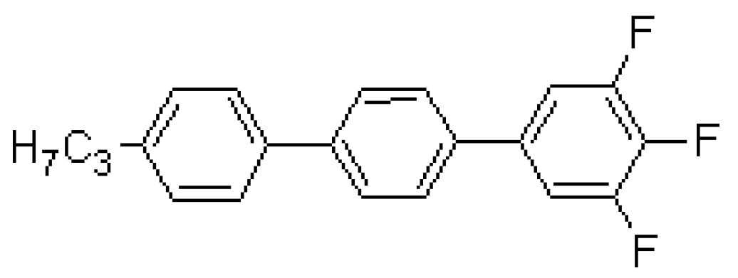
Figure 1. Chemical structure of trifluoro-terphenyl compound.
Crystals 10 00765 g001
Figure 2. Temperature-dependent birefringence of TL-216 and UCF-216 at λ = 633 nm and 1 kHz. Dots are measured data and solid lines are fitting curves with Equation (1). The fitting parameters are listed in Table 2.
Crystals 10 00765 g002
Figure 3. Temperature-dependent viscoelastic constant of TL-216 and UCF-216. Dots are measured data and solid lines are fitting curves using Equation (2). The fitting parameters are listed in Table 2.
Crystals 10 00765 g003
Figure 4. Measured (red line) voltage-dependent phase change of a transmissive TL-216 test cell at λ = 633 nm and 1 kHz. Cell gap is d = 4.99 μm, with V2π = 4.7 Vrms at T = 40 °C in (a) and with V2π = 4.9 Vrms at T = 50 °C in (b). If we operate TL-216 at 50 °C, we could use a slightly thinner cell gap (4.93 μm transmissive cell or 2.47 μm reflective LCoS, blue line in (b)) to increase V2π to 5 Vrms.
Crystals 10 00765 g004
Figure 5. Measured (red line) voltage-dependent phase change of a transmissive UCF-216 test cell at λ = 633 nm and 1 kHz. Cell gap is d = 5.01 μm, with V2π = 2.9 Vrms at T = 40 °C in (a) and with V2π = 3 Vrms at T = 50 °C in (b). If we allow V2π = 5.0 Vrms, then we can reduce the cell gap to 4.14 μm (blue line in (b)), which is equivalent to 2.07 μm in a reflective LCoS panel.
Crystals 10 00765 g005
Figure 6. Measured photostability of E7 and Merck TL-216 with a blue laser at λ = 465 nm at 22 °C. Probing laser λ = 633 nm.
Crystals 10 00765 g006
Figure 7. A photo of damaged E7 test cell taken between crossed polarizers on a white light table. The pink area shows homogeneous alignment, the middle circle is the laser exposure area, and the black spot is the damaged pattern. Both filling holes were sealed by epoxy sealants.
Crystals 10 00765 g007
Table 1. Measured physical properties of TL-216 and UCF-216 at T = 22 °C.
LC mixtureTL-216UCF-216
Tc (°C)80.081.8
Tm (°C)−20−20
Δn @ 633 nm0.2050.215
Δε @ 1 kHz5.57.6
ε @ 1 kHz4.24.2
K11 (pN)14.414.6
K33 (pN)19.6---
γ1/K11 (ms/µm2)19.014.5
Table 2. Fitting parameters obtained through Equations (1) and (2).
LC MixtureΔn0βA
(ms/µm2)
Ea
(meV)
TL-2160.3500.2941.23 × 10−6406.0
UCF-2160.3090.2032.12 × 10−4272.0
Table 3. Measured response time of a transmissive TL-216 cell with d = 4.99 μm, and the extrapolated response time to the corresponding reflective cells at 40 °C and 50 °C. λ = 633 nm.
T (°C)d (μm)Vth (V)V (V)τon (ms)τoff (ms)τtotal (ms)
Transmissive
τtotal (ms)
Reflective
404.991.94.717.730.448.212.0
404.671.95.112.526.639.29.8
504.991.84.99.718.127.76.9
504.931.85.09.017.626.66.7
Table 4. Measured response time of a transmissive UCF-216 cell with d = 5.01 μm, and the extrapolated response time to the corresponding reflective cells at 40 °C and 50 °C. λ = 633 nm.
T
(°C)
d
(μm)
Vth (V)V2π(V)τon (ms)τoff (ms)τtotal (ms)
Transmissive
τtotal (ms)
Reflective
405.011.32.9318.5321.6940.2210.06
404.001.35.03.4913.8317.324.33
505.011.23.011.1414.825.946.48
504.141.25.02.4410.112.543.14