Numerical Analysis of a Novel Shaft Lining Structure in Coal Mines Consisting of Hybrid-Fiber-Reinforced Concrete
Abstract
:1. Introduction
2. Establishment of the Numerical Model of the HFRC Shaft Lining Structure
2.1. Element Type
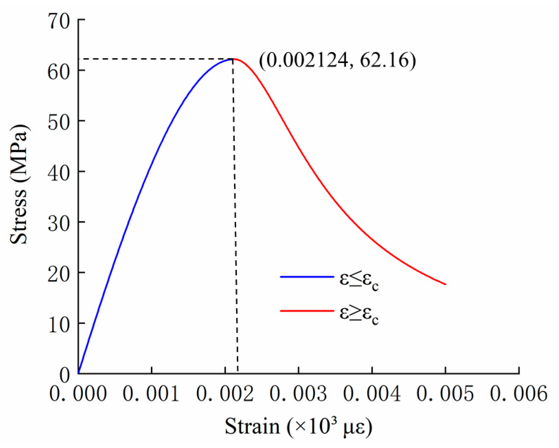
2.2. Material Constitutive Model and Parameters
2.3. Shaft Lining Simulation Scheme and Boundary Conditions
3. Analysis of Numerical Simulation Results
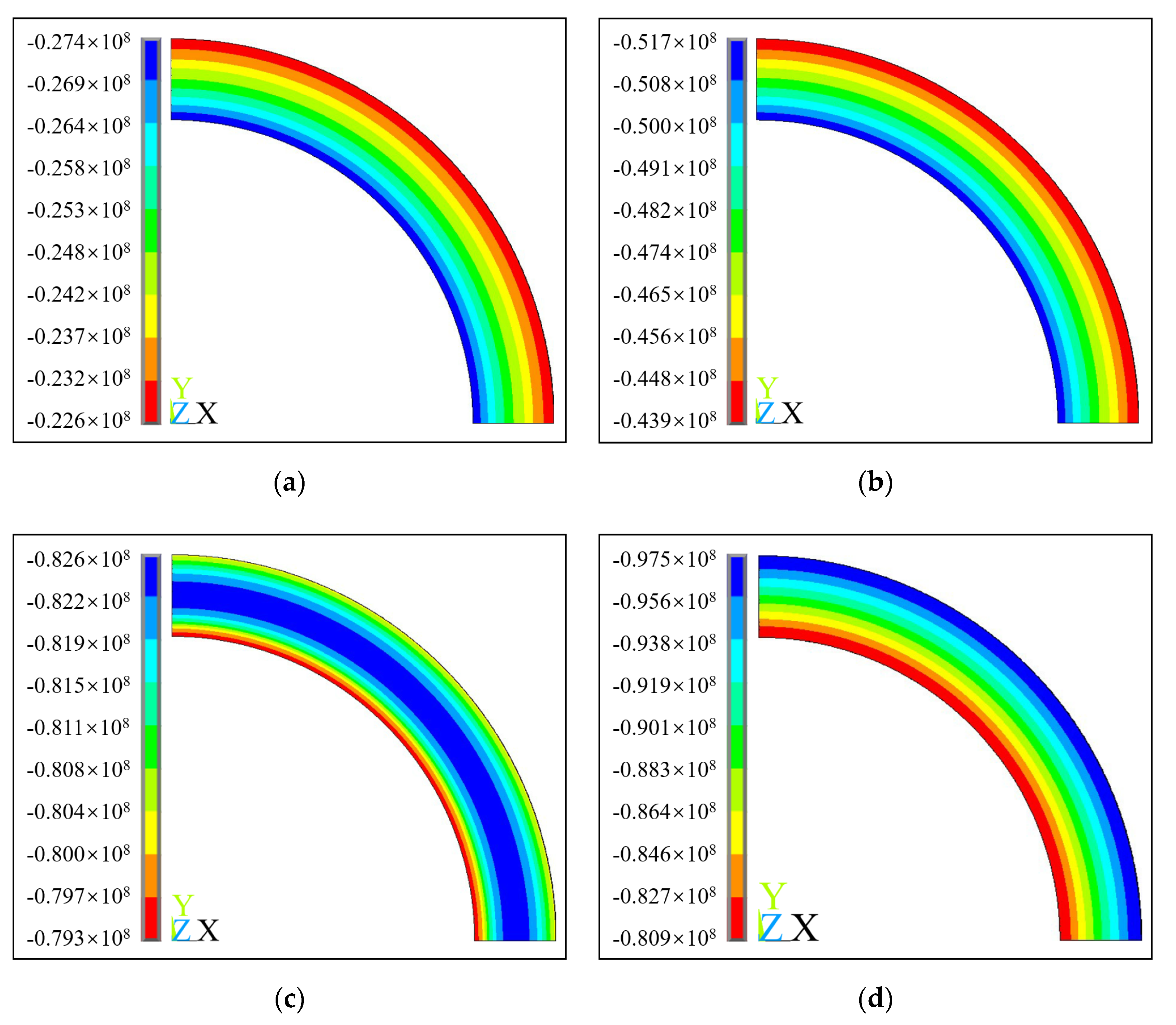
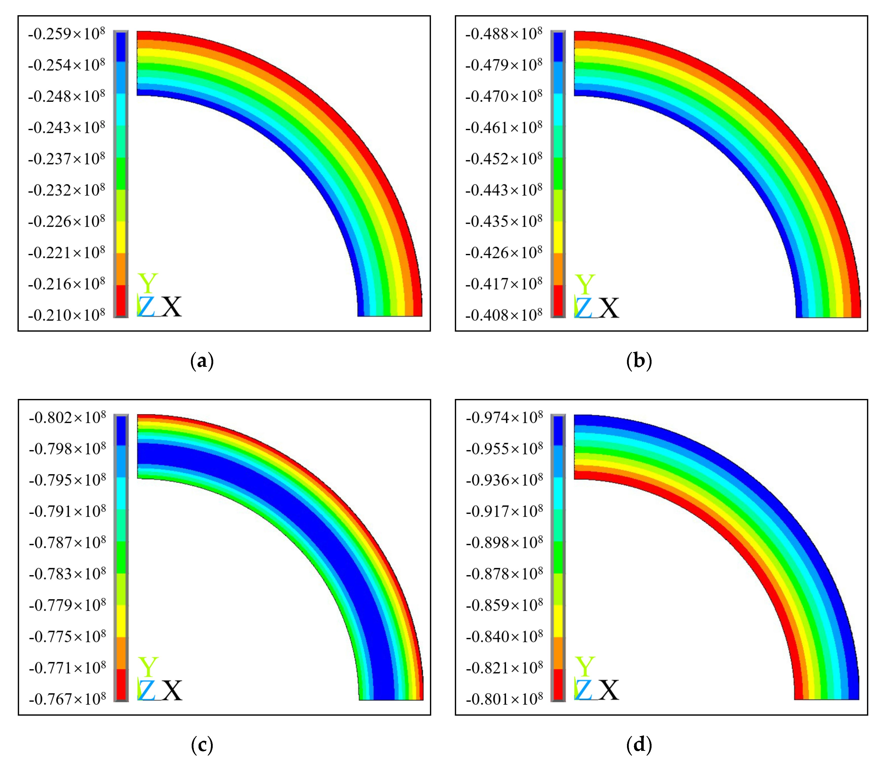
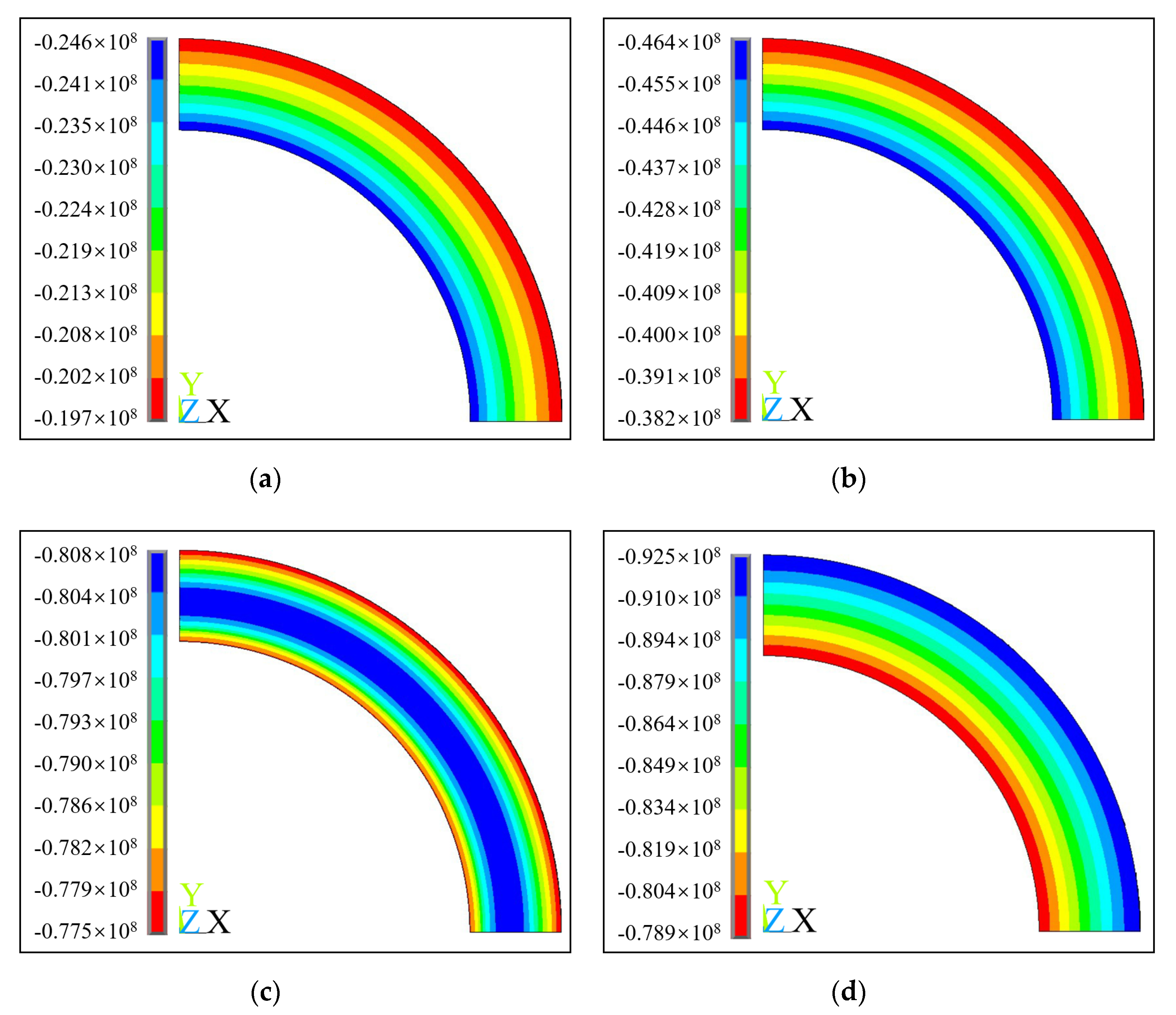
3.1. Relationship between Hoop Stress and Surface Load
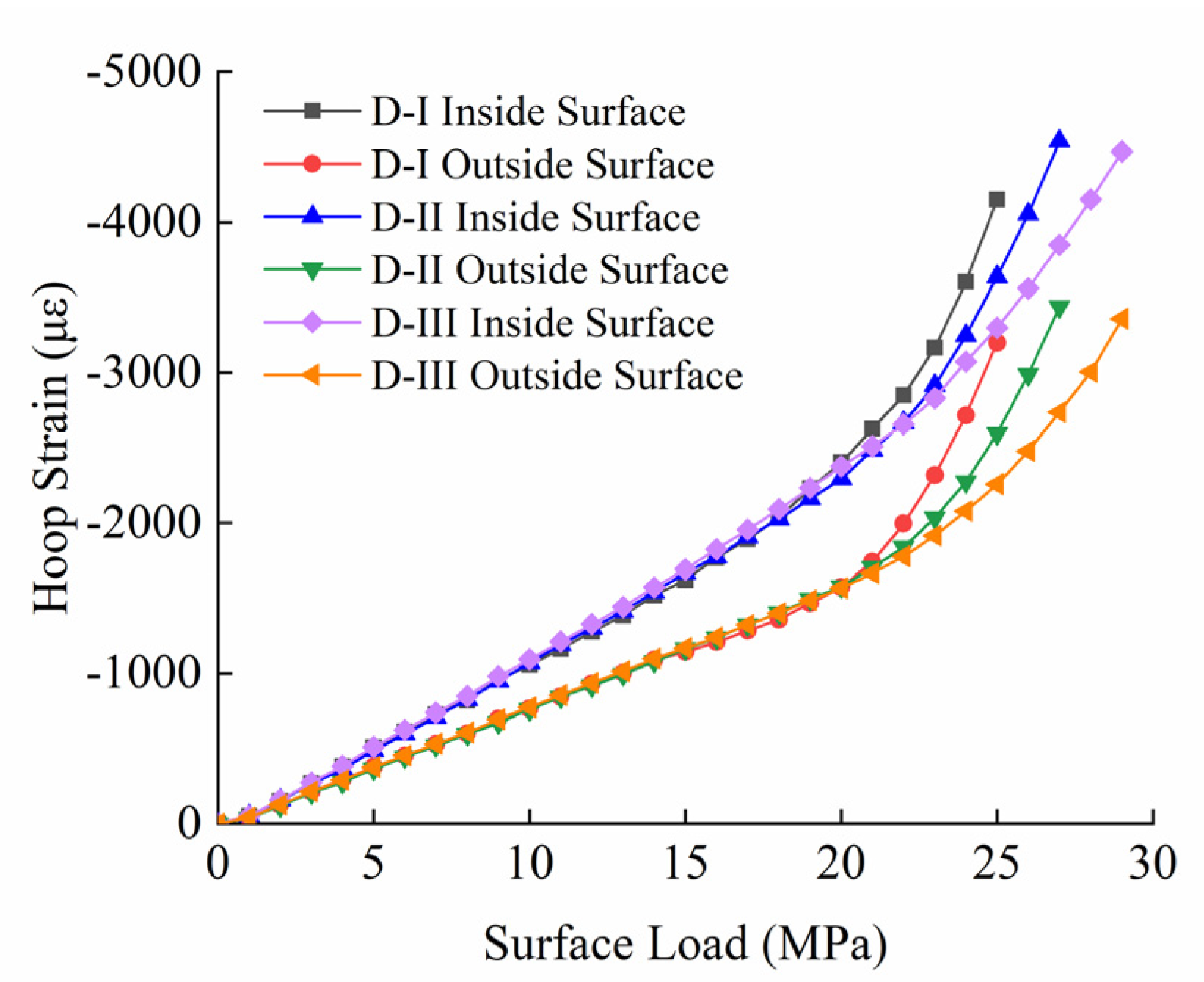
3.2. Relationship between Hoop Strain and Surface Load
3.3. Analysis of the Ultimate Capacity of the Shaft Lining Structure
3.4. Model Test Verification of the Shaft Lining Structure
3.4.1. Model Test of the Shaft Lining Structure
3.4.2. The Relationship between Shaft Lining Hoop Strain and Surface Load
3.4.3. Verification of the Empirical Formula for the Ultimate Capacity of the Shaft Lining
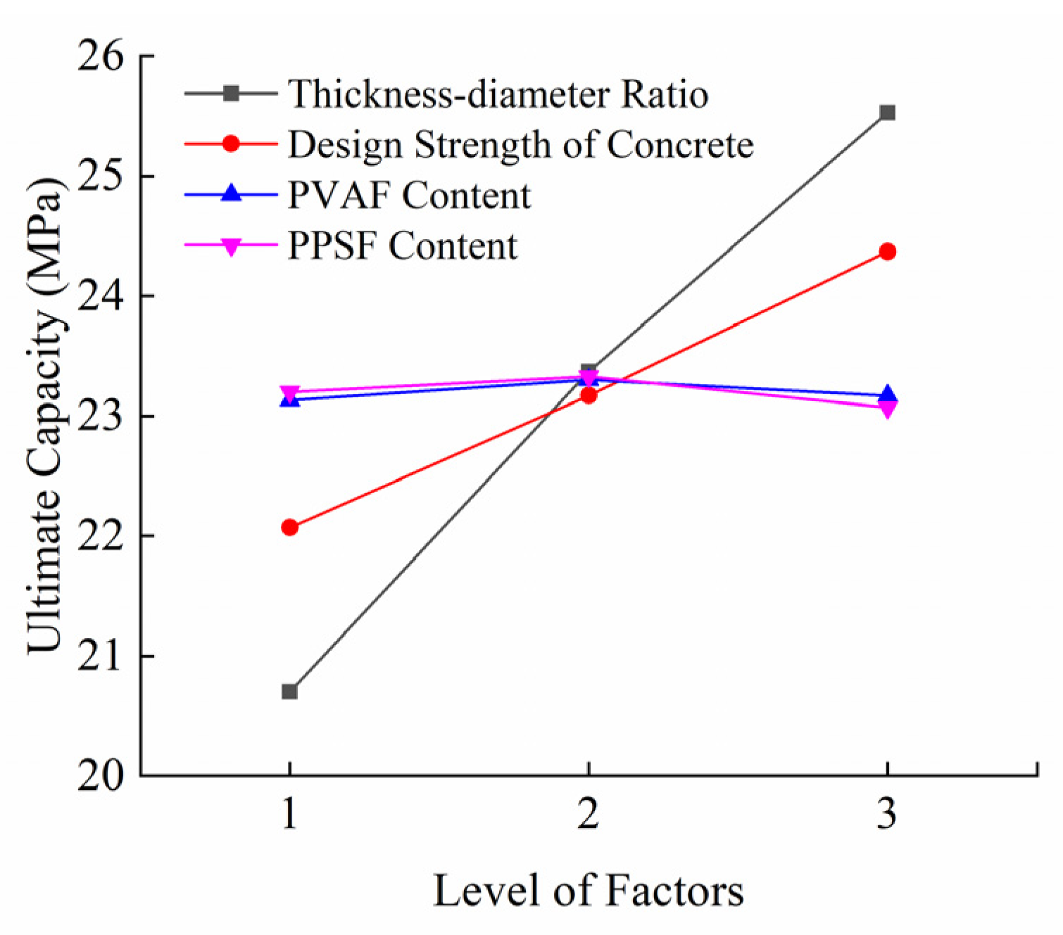
4. Range Analysis of the Ultimate Capacity of the Shaft Lining Structure
5. Conclusions
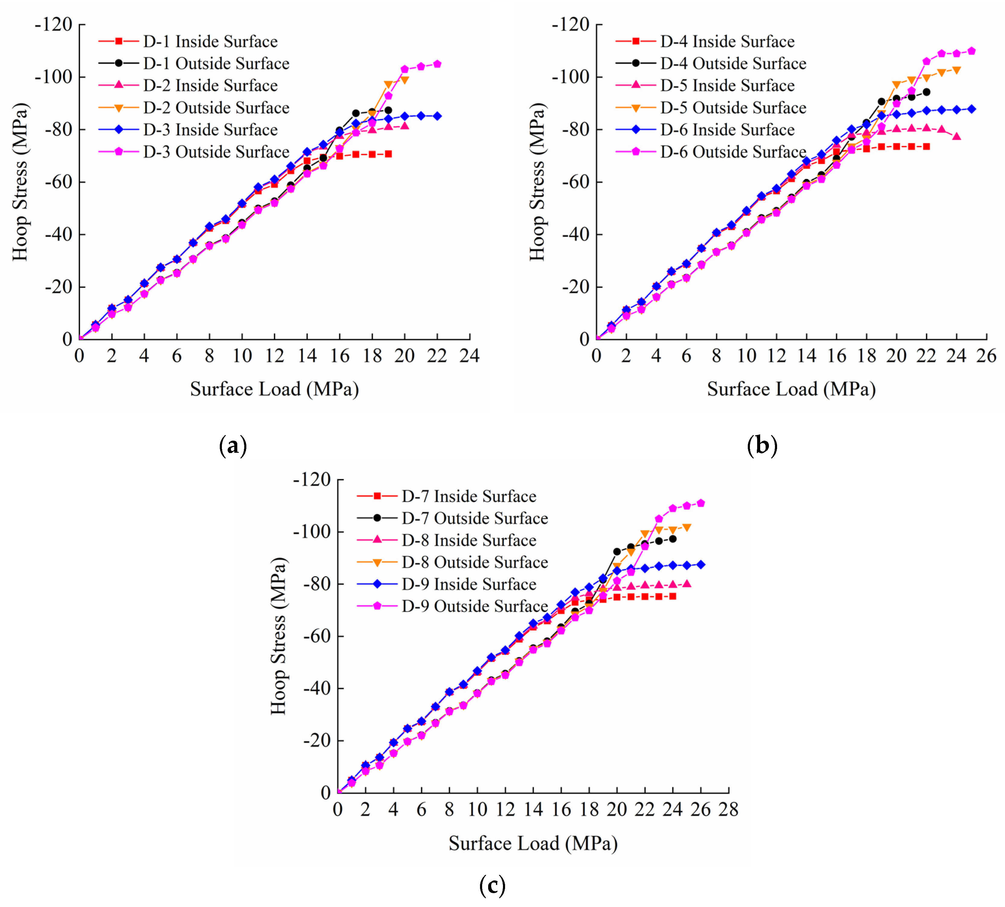
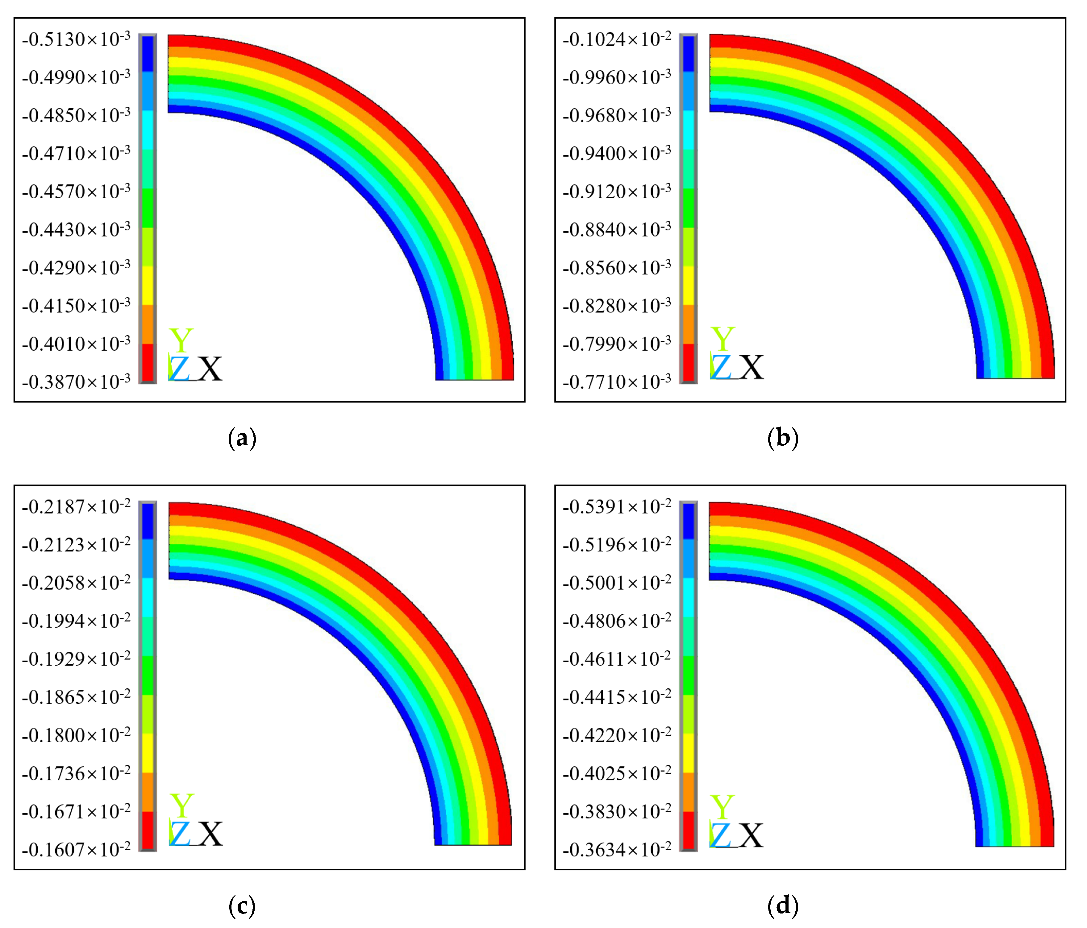
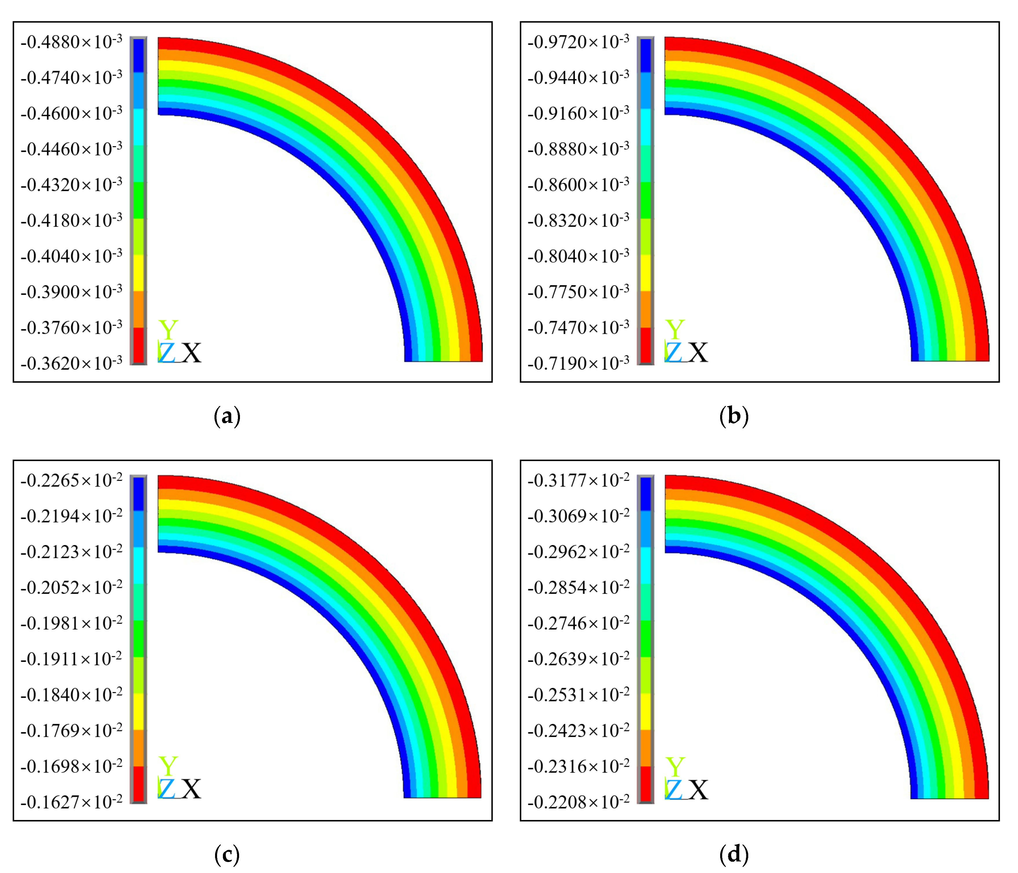
- From the hoop stress surface load curve and hoop strain surface load curve obtained from the numerical simulation, it can be seen that the maximum hoop stress gradually increases with the surface load, showing a trend of gradual transition from the inside surface to the outside surface. When the shaft lining is broken, the hoop stress at the outside surface is greater than that at the inside surface. The hoop strain at the inside and outside surfaces of the shaft lining is always a compressive strain, and the hoop strain at the inside surface is always greater than that at the outside surface.
- The results of numerical simulation show that the compressive strength of concrete is improved to a certain extent because the concrete in the inside and outside surfaces of the shaft lining model is in a bidirectional compression state and three-dimensional compression state, respectively. When the shaft lining is damaged, the maximum hoop stress values of concrete on the inside and outside surfaces of each shaft lining reach 87.8 MPa, 97.5 MPa, 105 MPa, 92.5 MPa, 103 MPa, 111 MPa, 97.3 MPa, and 103 MPa, respectively. The maximum hoop stress exceeds the uniaxial compressive strength of this kind of concrete.
- According to the results of numerical simulation, an empirical formula for the ultimate capacity of the HFRC shaft lining was obtained by fitting, and the rationality of the empirical formula was verified by the shaft lining model test. The maximum relative error between the calculated value of the shaft lining ultimate capacity and the test value is only 6.69%, and the relative error is small, which provides a reference for designing this type of shaft lining structure.
- The order of influence on the ultimate capacity of this kind of HFRC shaft lining structure is the thickness–diameter ratio, design strength of concrete, PPSF content and PVAF content. The ultimate capacity of the shaft lining structure markedly increases with the increase in the thickness–diameter ratio and the design strength of the concrete. However, the increase in the amount of hybrid-fiber cannot significantly enhance the ultimate capacity of the shaft lining structure, and the effect of adding more fibers is slightly worse. Therefore, the optimal blending amount of hybrid-fiber is 1.092 kg/m3 of PVAF and 5 kg/m3 of PPSF.
Author Contributions
Funding
Conflicts of Interest
References
- Zhang, T.; Yang, W.H.; Chen, G.H.; Huang, J.H.; Han, T.; Zhang, C. Monitoring and analysis of hydration heat temperature field for high performance mass concrete freezing shaft lining. J. Min. Saf. Eng. 2016, 33, 290–296. [Google Scholar]
- Yao, Z.S.; Cheng, H.; Zhang, G.Y.; Wang, X.Q. Research on site measurement of outer shaft wall stressing in freezing sinking shaft in special thick alluvium. Coal Sci. Technol. 2004, 32, 49–52. [Google Scholar]
- Song, L.; Yang, W.H.; Li, H.P. Monitoring of freezing shaft sinking in ultra-deep alluvium of guotun coal mine. J. Min. Saf. Eng. 2010, 27, 19–23. [Google Scholar]
- Xue, W.P.; Zhu, Q.; Yao, Z.S.; Song, H.Q.; Yang, L. Influence of high permeability pore water pressure on physical and mechanical properties of shaft lining concrete. J. Mater. Eng. 2019, 37, 262–265, 270. [Google Scholar]
- Xue, W.P.; Yao, Z.S.; Kong, G.; Xie, D.Z.; Wu, H. Experimental study on mechanical properties of shaft lining concrete under stress-seepage coupling. Bull. Chin. Ceram. Soc. 2018, 37, 985–989. [Google Scholar]
- Yao, Z.S.; Gao, Y.; Song, H.Q. Experimental study on crack control and anti-permeability of high performance concrete in freezing shaft lining. Bull. Chin. Ceram. Soc. 2014, 33, 918–922. [Google Scholar]
- Barr, B.; Newman, P.D. Toughness of polypropylene fibre-reinforced concrete. Composites 1985, 16, 48–53. [Google Scholar] [CrossRef]
- Noushini, A.; Samali, B.; Vessalas, K. Effect of poly vinyl alcohol (PVA) fibre on dynamic and material properties of fibre reinforced concrete. Constr. Build. Mater. 2013, 49, 374–383. [Google Scholar] [CrossRef]
- Zhang, R.; Jin, L.; Tian, Y.; Dou, G.; Du, X. Static and dynamic mechanical properties of eco-friendly polyvinyl alcohol fiber-reinforced ultra-high-strength concrete. Struct. Concr. 2019, 20, 1051–1063. [Google Scholar] [CrossRef]
- Liang, N.H.; Liu, X.R.; Sun, J. Experimental study of crack resistance of multi-scale polypropylene fiber reinforced concrete. J. China Coal Soc. 2012, 37, 1304–1309. [Google Scholar]
- Banthia, N.; Gupta, R. Hybrid fiber reinforced concrete (HyFRC): Fiber synergy in high strength matrices. Mater. Struct. 2004, 37, 707–716. [Google Scholar] [CrossRef]
- Kang, S.T.; Jeong, C.; Kyung-Taek, K.; Seok, L.K.; Yeon, L.B. Hybrid effects of steel fiber and microfiber on the tensile behavior of ultra-high performance concrete. Compos. Struct. 2016, 145, 37–42. [Google Scholar] [CrossRef]
- Sanchayan, S.; Foster, S.J. High temperature behaviour of hybrid steel–PVA fibre reinforced reactive powder concrete. Mater. Struct. 2016, 49, 769–782. [Google Scholar] [CrossRef]
- Yao, Z.S.; Li, X.; Fu, C.; Xue, W.P. Mechanical Properties of Polypropylene Macrofiber-Reinforced Concrete. Adv. Mater. Sci. Eng. 2019, 2019, 7590214. [Google Scholar] [CrossRef] [Green Version]
- Ramesh, B.; Gokulnath, V.; Krishnan, S.V. Influence of M-Sand in self compacting concrete with addition of glass powder in M-25 grade. Mater. Today Process. 2020, 22, 535–540. [Google Scholar]
- Yao, Z.S. An experimental study on steel fiber reinforced high strength concrete shaft lining in deep alluvium. Chin. J. Rock Mech. Eng. 2005, 24, 1253–1258. [Google Scholar]
- Qin, B.D.; Liu, X.L.; Liu, S.F. Experimental study on ultimate strength and failure features of shaft wall with hybrid fiber reinforced high strength concrete. Rail. Eng. 2017, 156–159. [Google Scholar]
- Yao, Z.S.; Li, X.; Wu, T.L.; Yang, L.; Liu, X.H. Hybrid-Fiber-Reinforced Concrete Used in Frozen Shaft Lining Structure in Coal Mines. Materials 2019, 12, 3988. [Google Scholar] [CrossRef] [Green Version]
- Qureshi, L.A.; Muhammad, U. Effects of Incorporating Steel and Glass Fibers on Shear Behavior of Concrete Column-Beam Joints. KSCE J. Civ. Eng. 2018, 22, 2970–2981. [Google Scholar] [CrossRef]
- Carozzi, F.G.; Milani, G.; Poggi, C. Mechanical properties and numerical modeling of Fabric Reinforced Cementitious Matrix (FRCM) systems for strengthening of masonry structures. Compos. Struct. 2014, 107, 711–725. [Google Scholar] [CrossRef]
- Radtke, F.K.F.; Simone, A.; Sluys, L.J. A computational model for failure analysis of fibre reinforced concrete with discrete treatment of fibres. Eng. Fract. Mech. 2010, 77, 597–620. [Google Scholar] [CrossRef]
- Jiao, L.; Tao, F. Bonding property and seismic behavior of reinforced concrete and finite element analysis. Arab. J. Geosci. 2020, 13, 45. [Google Scholar] [CrossRef]
- Palanivelu, S. Flexural Behaviour of a Cold-Formed Steel-Concrete Composite Beam with Channel Type Shear Connector—An Experimental and Analytical Study. Civ. Environ. Eng. Rep. 2019, 29, 228–240. [Google Scholar] [CrossRef] [Green Version]
- Xue, J. Crack Analysis of Reinforced Concrete Structure based on ANSYS. Int. J. Civ. Eng. Mach. Manu. 2019, 4, 27–33. [Google Scholar]
- Yao, Z.S.; Gui, J.G.; Cheng, H.; Rong, C.X. Numerical simulation of composite shift lining of inner steel cylinder and high strength reinforced concrete. J. Guangxi Univ. Nat. Sci. Ed. 2010, 35, 35–38. [Google Scholar]
- Wu, J. Study on Mechanical Characteristics of inner Shaft Lining at Frozen Shaft in West Area. Master’s Thesis, Anhui University Science Technology, Huainan, China, 2013. [Google Scholar]
- Lu, H.L.; Cui, G.X. Mechanical mechanism of shaft lining structure in thick alluvium. J. China Univ. Min. Technol. 1999, 28, 539–543. [Google Scholar]
- Cai, H.B.; Li, X.F.; Cheng, H.; Yao, Z.S.; Wang, F.; Qian, W.W. Research on the structure of shaft lining with asphalt block and steel-reinforced concrete at deep shaft ingate and its application. J. Min. Saf. Eng. 2018, 35, 27–33. [Google Scholar]
- Chinese Standard GB50010-2010. China Ministry of Housing and Urban-Rural Development. In Code for Design of Concrete Structures; China Architecture and Building Press: Beijing, China, 2013. (In Chinese)




| NO. | Compressive Strength/MPa | Axial Compressive Strength/MPa | Peak Compressive Strain/με | Elastic Modulus/MPa |
|---|---|---|---|---|
| C-1 | 80.6 | 62.16 | 2.124 × 10³ | 3.787 × 10⁴ |
| C-2 | 86.8 | 68.83 | 2.203 × 10³ | 3.838 × 10⁴ |
| C-3 | 89.7 | 73.11 | 2.246 × 10³ | 3.860 × 10⁴ |
| C-4 | 81.5 | 62.57 | 2.141 × 10³ | 3.784 × 10⁴ |
| C-5 | 84.1 | 68.12 | 2.182 × 10³ | 3.832 × 10⁴ |
| C-6 | 92.4 | 74.54 | 2.258 × 10³ | 3.875 × 10⁴ |
| C-7 | 78.2 | 61.45 | 2.137 × 10³ | 3.798 × 10⁴ |
| C-8 | 82.9 | 67.69 | 2.195 × 10³ | 3.825 × 10⁴ |
| C-9 | 90.7 | 73.68 | 2.269 × 10³ | 3.873 × 10⁴ |
| NO. | Thickness-Diameter Ratio/λ | Design Strength of Concrete/MPa | PVAF Content/kg·m−3 | PPSF Content/kg·m−3 |
|---|---|---|---|---|
| D-1 | 0.2675 | C70 | 0.728 | 4 |
| D-2 | 0.2675 | C75 | 1.092 | 5 |
| D-3 | 0.2675 | C80 | 1.456 | 6 |
| D-4 | 0.2908 | C70 | 1.092 | 6 |
| D-5 | 0.2908 | C75 | 1.456 | 4 |
| D-6 | 0.2908 | C80 | 0.728 | 5 |
| D-7 | 0.3140 | C70 | 1.456 | 5 |
| D-8 | 0.3140 | C75 | 0.728 | 6 |
| D-9 | 0.3140 | C80 | 1.092 | 4 |
| NO. | Thickness–Diameter Ratio | Concrete Strength Grade/MPa | PVAF Volume Fraction/% | PPSF Volume Fraction/% | Axial Compressive Strength of Concrete/MPa | Ultimate Capacity/MPa |
|---|---|---|---|---|---|---|
| D-1 | 0.2675 | C70 | 0.0564 | 0.4396 | 62.16 | 19.5 |
| D-2 | 0.2675 | C75 | 0.0847 | 0.5495 | 68.83 | 20.9 |
| D-3 | 0.2675 | C80 | 0.1129 | 0.6593 | 73.11 | 21.7 |
| D-4 | 0.2908 | C70 | 0.0847 | 0.6593 | 62.57 | 22.2 |
| D-5 | 0.2908 | C75 | 0.1129 | 0.4396 | 68.12 | 23.3 |
| D-6 | 0.2908 | C80 | 0.0564 | 0.5495 | 74.54 | 24.6 |
| D-7 | 0.3140 | C70 | 0.1129 | 0.5495 | 61.45 | 24.5 |
| D-8 | 0.3140 | C75 | 0.0264 | 0.6593 | 67.69 | 25.3 |
| D-9 | 0.3140 | C80 | 0.0847 | 0.4396 | 73.68 | 26.8 |
| NO. | Inner Radius/mm | Thickness/mm | Thickness–Diameter Ratio | Design Strength of Concrete/MPa | Reinforcement Ratio/% | PVAF Content/kg·m−3 | PPSF Content/kg·m−3 |
|---|---|---|---|---|---|---|---|
| D-I | 729.8 | 97.6 | 0.2675 | C70 | 0.6 | 1.092 | 5 |
| D-II | 716.6 | 104.2 | 0.2908 | C75 | 0.6 | 1.092 | 5 |
| D-III | 704.0 | 110.5 | 0.3140 | C80 | 0.6 | 1.092 | 5 |
| NO. | Thickness-Diameter Ratio/λ | Design Strength of Concrete/MPa | PVAF Volume Rate/% | PPSF Volume Rate/% | Axial Compressive Strength of Concrete/MPa | Ultimate Capacity/MPa | Relative Error/% | |
|---|---|---|---|---|---|---|---|---|
| Test Value/MPa | Calculated Value/MPa | |||||||
| D-I | 0.2675 | C70 | 0.0847 | 0.5495 | 63.35 | 23.6 | 22.02 | 6.69 |
| D-II | 0.2908 | C75 | 0.0847 | 0.5495 | 69.23 | 26.2 | 25.89 | 1.18 |
| D-III | 0.3140 | C80 | 0.0847 | 0.5495 | 74.59 | 28.7 | 29.94 | 4.32 |
| Level of Factors | A | B | C | D | Optimal Combination | Order of Factors | |
|---|---|---|---|---|---|---|---|
| Ultimate capacity | k1 | 20.70 | 22.07 | 23.13 | 23.20 | A3B3C2D2 | ABDC |
| k2 | 23.37 | 23.17 | 23.30 | 23.33 | |||
| k3 | 25.53 | 24.37 | 23.17 | 23.07 | |||
| R | 4.83 | 2.30 | 0.17 | 0.26 | |||
© 2020 by the authors. Licensee MDPI, Basel, Switzerland. This article is an open access article distributed under the terms and conditions of the Creative Commons Attribution (CC BY) license (http://creativecommons.org/licenses/by/4.0/).
Share and Cite
Wang, X.; Cheng, H.; Wu, T.; Yao, Z.; Huang, X. Numerical Analysis of a Novel Shaft Lining Structure in Coal Mines Consisting of Hybrid-Fiber-Reinforced Concrete. Crystals 2020, 10, 928. https://doi.org/10.3390/cryst10100928
Wang X, Cheng H, Wu T, Yao Z, Huang X. Numerical Analysis of a Novel Shaft Lining Structure in Coal Mines Consisting of Hybrid-Fiber-Reinforced Concrete. Crystals. 2020; 10(10):928. https://doi.org/10.3390/cryst10100928
Chicago/Turabian StyleWang, Xuesong, Hua Cheng, Taoli Wu, Zhishu Yao, and Xianwen Huang. 2020. "Numerical Analysis of a Novel Shaft Lining Structure in Coal Mines Consisting of Hybrid-Fiber-Reinforced Concrete" Crystals 10, no. 10: 928. https://doi.org/10.3390/cryst10100928
APA StyleWang, X., Cheng, H., Wu, T., Yao, Z., & Huang, X. (2020). Numerical Analysis of a Novel Shaft Lining Structure in Coal Mines Consisting of Hybrid-Fiber-Reinforced Concrete. Crystals, 10(10), 928. https://doi.org/10.3390/cryst10100928


