Varying the Dimensionality of Cu(II)-Based Coordination Polymers Through Solvent Influence
by
 , , and
Irina A. Kühne
1,2 ,
,
Anthony B. Carter
1, 
George E. Kostakis
3 ,
,
Christopher E. Anson
1 and
Annie K. Powell
1,4,* 1
Institut für Anorganische Chemie, Karlsruher Institut für Technologie, 76131 Karlsruhe, Germany
2
FZU-Institute of Physics of the Czech Academy of Sciences, Na Slovance 1999/2, 8, 182 21 Prague, Czech Republic
3
Department of Chemistry, School of Life Sciences, University of Sussex, Sussex BN1 9QJ, UK
4
Institute of Nanotechnology, Karlsruhe Institute of Technology, Herrmann-von-Helmholtz-Platz 1, 76344 Eggenstein-Leopoldshafen, Germany
*
Author to whom correspondence should be addressed.
Crystals 2020, 10(10), 893; https://doi.org/10.3390/cryst10100893
Submission received: 8 September 2020
/
Revised: 25 September 2020
/
Accepted: 29 September 2020
/
Published: 2 October 2020
(This article belongs to the Special Issue Crystal Structure and Thermal Studies of Coordination Compounds)
Abstract
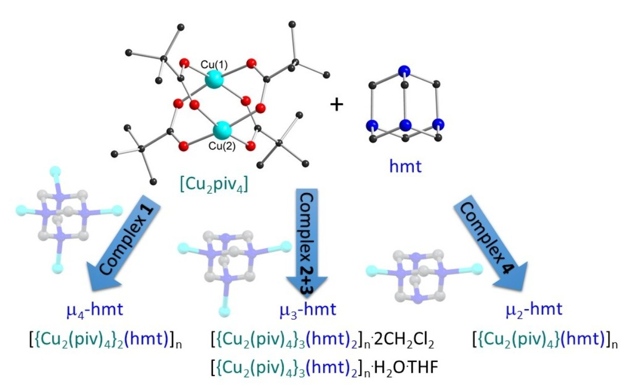
:This work reports the synthesis and structure of a large porous zeotype network observed within compound (1) using {Cu2(piv)4} as the linking unit (piv = pivalate). The slow in situ formation of the hmt ligand (hexamethylenetetramine) appears to be key in generating a µ4-bridging mode of the hmt-node. Attempts to improve the low yield of compound (1) using different solvent layer diffusion methods resulted in the µ3-hmt complexes (2) and (3). Both compounds exhibit a 3D network of two intertwined chiral networks. Strong hydrogen bonding present in (3) leads to the formation of intertwined, DNA-like double-helix structures. The use of bulky solvents in the synthesis of compound (4) leads to the structure crystallizing solvent-free. The packing of (4) is dominated by energy minimization, which is achieved when the 1D-“cylinders” pack into the closest possible arrangement. This work highlights the potential for solvent controlled synthesis of extended copper-hmt systems.

1. Introduction
Metal-organic frameworks (MOFs)/coordination polymers (CPs) and zeotypes are currently of great interest due to their potential use in a wide range of applications from gas storage to carbon capture materials [1,2,3,4] and catalysis [5,6] to semiconductors [7,8,9]. These can also demonstrate interesting properties in the field of molecular magnetism [10,11,12,13,14,15]. The general design principle for MOFs/CPs is to combine two building blocks: a node, which is often a metal center or polymetallic cluster, and an organic linker. This allows for a modular design with the ability to target highly specific geometries and pore sizes using reticular chemistry [16]. Hexamethylenetetramine (hmt) provides four potential N-donors and is suitable for the construction of super-tetrahedral networks. To date, several CPs have been reported utilizing this ligand, primarily with AgI and CdII [17,18,19,20,21,22,23,24]. The CuII “paddle wheel” {Cu2(O2CR)4} motif is widely used as a linear metal-based spacer in the MOF community. The two apical sites can accept organic linkers to form networks [25,26,27]. Currently, the vast majority of reported combinations of hmt with CuII paddle wheel species have described either 1D chains [28,29,30,31,32] or 2D networks [33,34,35]. The hmt ligand serves as a μ2 or μ3 bridging linker with only a few examples of a μ4-bridged 3D framework [36,37]. Other CuII-hmt networks have utilized larger copper-halide clusters such as “CuII5Cl6” or “CuII6Cl6” nodes as a means to increase the dimensionality [38]. In this work, we present the first hmt/CuII paddle wheel-based zeotype structure (1) where the hmt tetrahedral node is μ4 bridging to four linear {Cu2(piv)4} units (piv = pivalate). Three additional hmt/CuII paddle wheel architectures (2–4) with μ3 and μ2 bridging modes are presented. The bridging modes of these are shown in Figure 1.
2. Results and Discussion
2.1. Synthetic Strategy
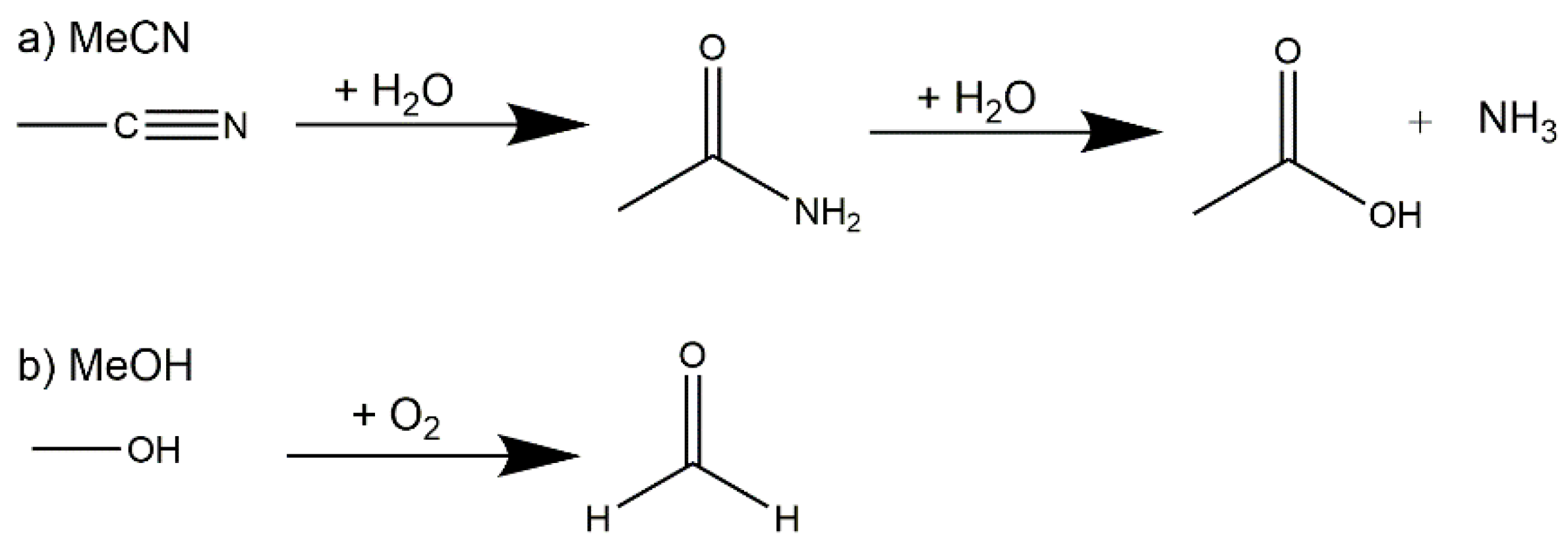
The full synthetic conditions for the four complexes can be found in Section 3. The zeotype-MOF (1) was produced whilst attempting to synthesize a mixed Cu-4f metal cluster, such as those we previously reported [39]. This serendipitous (but reproducible) result occurred when small amounts of hmt were formed in situ during the synthesis via a plausible three step route involving the hydrolysis of acetonitrile to ammonia and the oxidation of methanol to formaldehyde (Scheme 1). Hexamethylenetetramine (hmt) can be formed in an aqueous reaction of ammonia and formaldehyde in a temperature range between 0–50 °C. This reaction can take place even with excess of either ammonia or formaldehyde [40].
The ammonia required for the formation of hmt is most likely produced by the hydrolysis of the acetonitrile used in the reaction mixture (see Scheme 1). Nitriles, such as acetonitrile, can be hydrolyzed in aqueous acids or bases under heating in a two-step process [41]. This procedure is known from nature as well, i.e., the enzymatic hydrolysis of nitriles to carboxylic acid, and has been studied with enzymes and microbiological cells, which follows either the nitrilase pathway or a nitrile hydratase followed by amidase pathway [42,43,44,45]. The hydration of nitriles is well-known with the obvious metal catalysts like RuII, AuI, RhI and MnIV centers, [46,47,48,49], which are often biomimic models. But there are also publications showing that CuII ions can catalyze the hydration of nitriles using, e.g., copper(II) acetate [50]. The activation of the C≡N bond occurs through coordination to the metal atoms, thus enhancing the rate of the hydration step [51]. The amide can be hydrolyzed in the second step (Scheme 1) under basic or acidic conditions, which leads to the formation of ammonia [52,53].
The formaldehyde, which is the second requirement for the formation of hmt, is probably formed through the oxidation of methanol (Scheme 1). It has been shown in the literature that lanthanides [54] as well as CuII [55] can catalyze the oxidation of methanol.
Due to the long crystallization time and the not unexpectedly very low yield of compound (1), an alternative synthetic route was envisioned to further develop this chemistry. We began exploring the intentional addition of hmt to the reaction mixture through layer diffusion to produce new CPs. This synthesis method was chosen as an alternative to the high-dilution principles often seen in macrocyclic chemistry with the aim of promoting larger porous network growth over the formation of discrete molecules which results when directly mixing the hmt and {Cu2(piv)4}. Compounds (2) and (3) were therefore produced by layering an aqueous solution of hmt, with a solution of {Cu2(piv)4} in CH2Cl2 or THF, respectively. In case of complex (3), the layering was done with the hmt water phase on the bottom of the vial due to the higher density of water compared to THF. Since THF and water are miscible, a “buffer layer” of 1 mL of pure THF was carefully placed on top of the water phase, before layering the {Cu2(piv)4} THF solution on top. This led to a very slow mixing at the interface, and a gradual color change could be observed already after one hour. After observing the pivotal effect that the solvent played in 3D structure formation, the same layering reaction was carried out using {Cu2(piv)4} in polyethyleneglycol (PEG-300), resulting in the formation of the solvent free 1D polymer (4).
2.2. Description of Crystal Structures
Single crystal X-ray analysis of the pale blue octahedral crystals of (1) revealed a 3D network of {Cu2(piv)4} paddlewheel species linked by μ4-hmt molecules, formally described as [{Cu2(piv)4}2(hmt)]n. This structure crystallizes in the cubic space group Fdm with Z = 136. The crystals of (1) are intrinsically very weakly diffracting as a consequence of the extensive disorder of the pivalate ligands resulting from the rotation of the {Cu2(piv)4} paddlewheels about their Cu...Cu vectors. The network consists of five- and six-membered rings with zeolite topology similar to that found in [Cd(H2O)3}34(hmt)17]Cl68, as reported by Fang et al. [56]. A schematic version of the structure is shown in Figure 2.
The 3D-network of (1) shows the MTN zeolite topology (ZSM-39), and contains two different types of cavities constructed of [Cu4(hmt)] units. The larger cavity consists of four six-membered rings and twelve five-membered rings, and therefore, has the Schläfli symbol 64.512, while the smaller one consists of 12 five-membered rings and is designated as a 512 cavity; see Figure 3. An hmt-ligand connected to four linear {Cu2(piv)4} units is located in the corners of the five- and six-membered rings. Each of the 64.512 cages is connected to four neighboring 64.512 cages face-sharing the six-membered rings. Additionally, the 64.512 units share the adjacent faces of neighboring 512 cavities. This leads to a continuous 3D sodalite-like network.
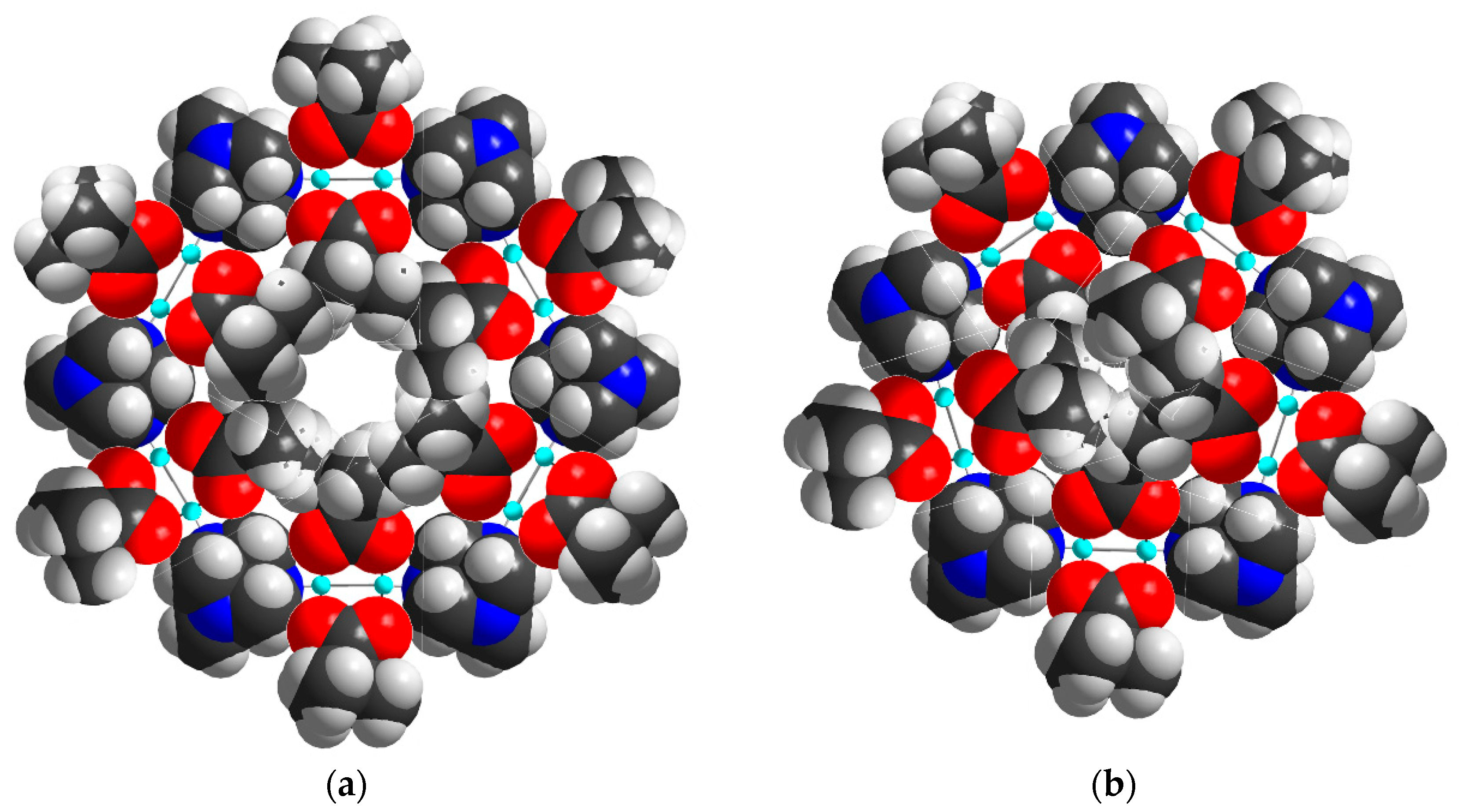
The diameter of the 64.512 cavity is 29.4 Å, while for the smaller 512 cavity, it is 21.9 Å. These are both larger than the cavities in the analogous Cd-MOF structure [56] as a result of the replacement of a single Cd ion linker with the larger CuII2 paddlewheel. The average N·(Cu2)·N distance of 6.97 Å is thus much larger than the N·(Cd)·N distance of 4.91 Å. However, due to the bulky pivalate groups around the metal centers, the solvent accessible volume is just about 12% compared to the cadmium compound’s calculated 65%, although this value drops to 46% when including the interstitial chloride anion required for charge balance. Space filling models of the hexagonal and pentagonal “windows” between the cavities in 1 (Figure 4) highlight the fact that even though both are large in diameter, the bulkiness of the pivalate groups around the CuII2 paddlewheels makes movement of guest molecules between the cavities essentially impossible. The hexagonal windows (between 64.512 cavities) have only a small hole at their centers, while the pentagonal windows (between the 64.512 and the 512 cavities or between two 512 cavities) are totally “corked”.
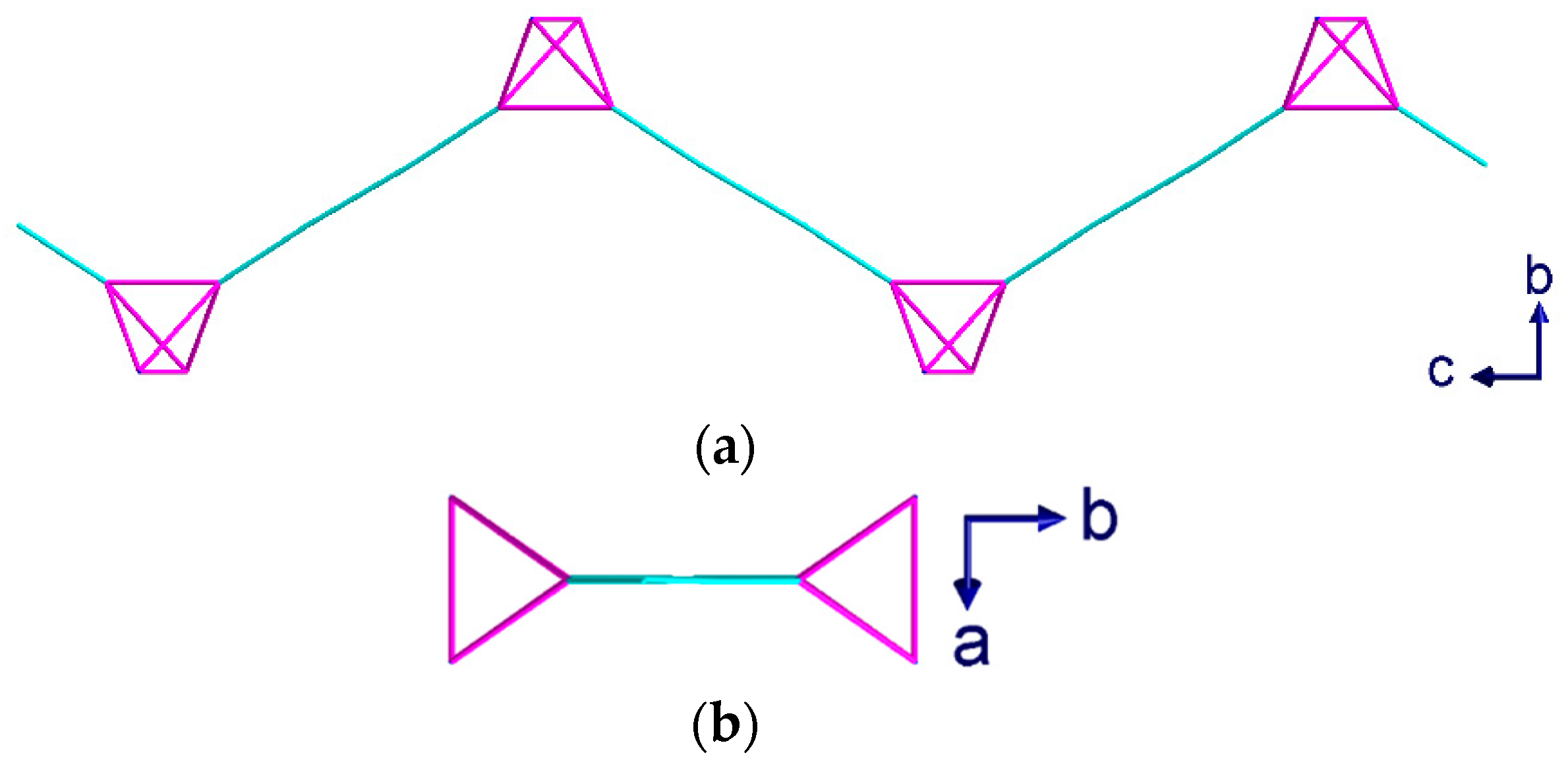
Green crystals of complex (2) were isolated from the aqueous phase of the water-DCM layer diffusion and analyzed using single crystal X-ray diffraction. Compound (2) crystallizes in the trigonal space group R with Z = 12 including two dichloromethane molecules per Z. Blue crystals of complex (3) were isolated from the interphase where the water-THF layer diffusion had mixed, and the crystals were analyzed using single crystal X-ray diffraction. Compound (3) also crystallizes in the trigonal space group R, but with Z = 9 and a single THF molecule per Z. In both (2) and (3), only three out of four hmt nitrogen atoms are connected to CuII-ions, resulting in a µ3-linker. This contrasts with compound (1), where the hmt is µ4-bridging. Meanwhile, within complex 1, the connection to the hmt node creates a linear {Cu2(piv4)} linker, while some of the Cu-N bonds within compounds 3 and 4 are not in line with the Cu…Cu axis, leading to a “bending” of the spacer (Figure 5a).
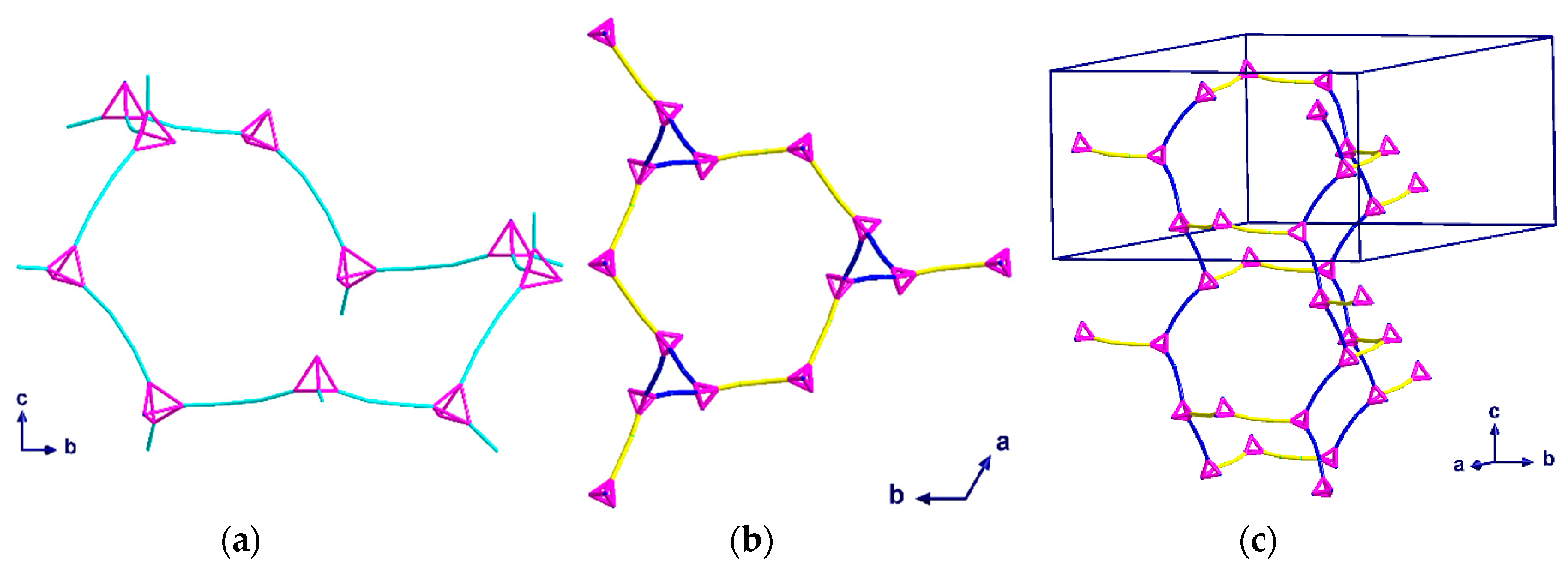
Compound (2) consists of distorted chair-shaped ten-membered rings (Figure 5a) which form a helical network. The overall structure contains two of these helices interpenetrating each other. This interpenetration is assisted through a weak solvent mediated interaction, [C20···Cl1 = 3.715 Å and ∠(CH···Cl) = 142°]. These interpenetrated helical networks form a 3D-structure with helices of both R and S chiralities along the c-axis (Figure 6a). All helices in the same network have the same orientation. The helices of each network are connected to each other by additional {Cu2(piv)4} units, which are perpendicular to the helices and are highlighted in yellow in Figure 5b,c. As the helices have a threefold symmetry along the c-axis, they are only visible as “triangles” when viewed down this axis.
Since the two interpenetrating helices are enantiomeric pairs, the space group is centrosymmetric. To demonstrate the interpenetration clearly, the two networks have been drawn in different colors in Figure 6.
Complex (3) consists of six- and ten-membered rings which assemble into chiral helices that are intertwined enantiomers forming a double-helix; again, the space group is centrosymmetric. A stronger solvent mediated interaction [O21···N4 = 2.924 Å] than that of (2) appears to play an important role in the alignment of the DNA-like double-helix structure. The helices have a six-fold rotation along the c-axis which causes the structure to appear as distorted “hexagons” when viewed down the c-axis (Figure 7a). As with (2), all helices in the same network have the same orientation. By overlaying the structure of the double-helix, the twist and orientation becomes more apparent (Figure 7b).
The six-membered rings, which are almost perpendicular to the helices, stack above each other in an ABCA repeating unit, with the six-fold symmetry resulting in every third six-member ring having the same position in the ab-plane (Figure 8a). When combining the perpendicular six-membered rings and the irregular “hexagons” from the helices, a pattern of regular and distorted six-membered rings along the c-axis is observed (Figure 8b).
The crystal structures of 2 and 3 are nonporous and do not contain any “useful” solvent-accessible volume. In both cases, the two interpenetrating networks result in a very efficient packing, with only small noninterconnecting cavities containing the lattice solvent molecules.
Blue-green crystals of (4) were grown from the interphase where the water-PEG layer had mixed, and the crystals were analyzed using single crystal X-ray diffraction. Compound (4) crystallizes in the monoclinic space group C2/c with Z = 4. As previously mentioned, this sample is particularly interesting due to the lack of solvent in the structure. Unlike the µ4-hmt compound (1), or µ3-hmt compounds (2) and (3), this compound is made of a repeating unit of two CuII2 paddlewheel dimers linked through a µ2-hmt ligand, resulting in a 1D-chain. As seen within complex 1, the {Cu2piv4} units within complex 4 are linked to a hmt node, to create an almost perfect linear linker.
The angle between the two linear CuII2 paddlewheel complexes is 114°, resulting in a zigzag arrangement of the hmt nodes (Figure 9a). This results in the structure appearing as a simple dimer when viewed down the c-axis (Figure 9b). Despite the clear zigzag nature seen in the topological representation, the 1D chains are best described as cylinders, which is apparent when considering the full size of the atoms in a space filling model (Figure 10a). Given that the PEG-based synthesis resulted in a structure with no interstitial solvent, the possibility for supramolecular packing interactions is limited. As such, the 1D chains pack into the densest possible configuration of cylinders, which is the close packed arrangement (Figure 10b), and therefore, there is no space for solvent to access this structure.
3. Experimental Section
3.1. Materials and Instrumentation
All chemicals were purchased from commercial sources and used as received. Solvents were HPLC grade and were used without further purification. Microanalytical data was collected on a Perkin Elmer Vario EL elemental analyzer. Infrared spectra were prepared as KBr disks and recorded on Perkin Elmer Spectrum GX spectrometer.
3.2. Single-Crystal X-ray Structure Determinations
X-ray crystallography was carried out on suitable single crystals using an Oxford Supernova diffractometer (complex 3), while compounds 1, 2 and 4 were measured using the Synchrotron Light Source ANKA. Datasets were measured using monochromatic Mo-Kα (complex 3) or synchrotron (complex 1,2,4) radiation and corrected for absorption. The temperature was controlled with an Oxford Cryosystream instrument. All structures were solved by dual-space direct methods (SHELXT) [57] and refined by full matrix least-squares on F2 for all data using SHELXL-2016 [57].
Crystals of 1 are intrinsically very weakly diffracting as a consequence of the extensive disorder of the pivalate ligands resulting from the rotation of the {Cu2(piv)4} paddlewheels about their Cu…Cu vectors. Using a synchrotron X-ray source, it was possible to measure a dataset at 0.96 Å resolution, but no significant intensity could be measured at higher resolutions.
For the structures of 1–4, all ordered non-H atoms (and also partial atoms corresponding to major disorder components) were refined with anisotropic thermal parameters. H atoms were placed in calculated positions. Similarity restraints were applied to C-CH3 distances in disordered t-butyl groups as appropriate. In the structure of 1, the hmt ligands and Cu atoms were ordered and refined anisotropically, with H atoms in calculated positions for the hmt ligan, and the pivalate ligands were (at least) threefold disordered by rotation about the Cu…Cu vector. The pivalate oxygens were modelled and refined with isotropic partial occupancy O atoms, applying similarity restraints to the Cu-O bond lengths. Typically, twelve oxygens (including symmetry-equivalents) with 1/3 occupancy were modelled around each Cu, and no attempt was made to divide these oxygens into disorder components using PART commands (indeed, for those Cu2(piv)4 units with threefold crystallographic symmetry about the Cu…Cu vector, this would be impossible). Some carboxylate C atoms could be identified and refined isotropically with arbitrary 1/3 occupancies; again, no attempt was made to assign these to disorder components. Electron density corresponding to a small minority of t-butyl C atoms could be found; where possible, this was refined, but it was not considered worthwhile or possible to restrain these partial atoms into “realistic” t-butyl groups. The crystallographic details for all compounds are summarized, and crystallographic data for the structures reported in this paper have been deposited with the Cambridge Crystallographic Data Centre as supplementary publication numbers CCDC 2017721 (complex 1), CCDC 2017722 (complex 2), CCDC 2017723 (complex 3), CCDC 2017724 (complex 4). Copies of the data can be obtained, free of charge, from https://www.ccdc.cam.ac.uk/structures/.
3.3. Synthesis of Complex (1)
A solution of o-vanillin oxime (0.066 g, 0.4 mmol) and sodium methoxide (0.013 g, 0.25 mmol) in methanol (10 mL) was added to a solution of [Cu2(piv)4(MeCN)2] (0.980 g, 0.20 mmol) and Dy(NO3)3·6H2O (0.091 g, 0.20 mmol) in methanol:acetonitrile (10 mL:10 mL). The resulting solution was stirred at room temperature for 10 min and then placed in a sealed Et2O bath. After one year, complex (1) crystallizes as blue octahedral crystals.
Yield 0.005 g (2% based upon Cu).
Anal. Calcd. for C46H94Cu4N4O24: C = 41.19, H = 7.06, N = 4.18; Found: C = 41.25, H = 6.94, N = 4.02.
IR (KBr):ν = 3438 (m), 2954 (w), 2923 (w), 2874 (w), 2361 (w), 1635 (m), 1458 (m), 1440 (w), 1371 (m), 1239 (s), 1048 (w), 1008 (s), 812 (m), 673 (m), 513 (m) cm−1.
Crystal parameters for 1: C46H84Cu4N4O16 (M =1203.33 g/mol): cubic, space group Fd m (no. 227), a = 62.018(8) Å, V = 238540(95) Å3, Z = 136, T = 150(2) K, λ = 0.79963 Å, μ(synchrotron) = 1.729 mm−1, Dcalc = 1.139 g/cm3, 82000 reflections measured (2.45° ≤ 2Θ ≤ 49.16°), 6465 unique (Rint = 0.0892, Rsigma = 0.0406) which were used in all calculations. Final R1 = 0.1284 (I > 2σ(I)), S = 1.600 and wR2 = 0.3919 (all data).
3.4. General Procedure for the Synthesis of Complexes (2), (3), and (4)
A solution of hexamethylenetetramine (0.007 g, 0.05 mmol) in water (10 mL) was layered over a solution of [Cu2(piv)4(MeCN)2] (0.454 g, 0.10 mmol) in dichloromethane (2) or polyethyleneglycol (PEG-300) (4). The reaction vessel was sealed and left to stand. In case of tetrahydrofuran (3), the layering is reversed due to the density of the solvents. For the synthesis of complex 3 and 4, the layering required a “buffer layer” of 1 mL of pure solvent, since THF and polyethylene glycol, respectively, are miscible with water. Therefore, 1 mL of pure THF was layered over the hmt-water phase in case of compound 3, while in case of compound 4, 1 mL of H2O was carefully placed on top of the Cu2(piv)4-PEG solution. This leads to a very slow mixing at the interface, and a gradual color change can be observed already after one hour.
3.4.1. Synthesis of Complex (2)
After one day, small green crystals of (2) had formed in the aqueous phase around the edge of the glass vial.
Yield 0.018 g (35% based upon hmt).
Anal. Calcd. for [C72H132Cu6N8O24]·2H2O: C = 45.25, H = 7.17, N = 5.86; Found: C = 45.18, H = 7.28, N = 5.87.
IR (KBr): ν = 3448 (w), 2962 (m), 2930 (m), 2873 (w), 2361 (w), 2342 (w), 1609 (s), 1539 (w), 1485 (s), 1463 (m), 1420 (s), 1377 (m), 1362 (m), 1240 (s), 1226 (s), 1059 (w), 1023 (s), 1009 (s), 988 (m), 927 (w), 897 (w), 843 (w), 807 (m), 789 (m), 703 (m), 668 (w), 623 (m), 516 (w), 448 (m) cm−1.
Crystal parameters for 2: C74H136Cl4Cu6N8O24 (M =2044.93 g/mol): trigonal, space group R (no. 148), a = 38.6947(13) Å, c = 23.6691(9) Å, V = 30691(2) Å3, Z = 12, T = 150(2) K, λ = 0.80000 Å, μ(synchrotron) = 1.934 mm−1, Dcalc = 1.328 g/cm3, 77325 reflections measured (4.74° ≤ 2Θ ≤ 64.09°), 16286 unique (Rint = 0.0550, Rsigma = 0.0408) which were used in all calculations. Final R1 = 0.0443 (I > 2σ(I)), S = 1.074 and wR2 = 0.1316 (all data).
3.4.2. Synthesis of Complex (3)
After one day, small pale blue crystals of (3) had formed in the mixed interphase around the edge of the glass vial or dropped to the bottom of the vial.
Yield 0.013 g (26% based upon hmt).
Anal. Calcd. for [C72H132Cu6N8O24].0.4THF.1.5H2O: C = 45.78, H = 7.21, N = 5.80; Found: C = 45.79; H = 7.22, N = 5.80.
IR (KBr): ν = 3443 (s), 2961 (m), 2872 (m), 2361 (w), 1620 (m), 1575 (s), 1485 (s), 1424 (s), 1383 (m), 1228 (m), 1183 (w), 898 (w), 788 (w), 673 (w), 614 (w), 570 (w), 430 (w) cm−1.
Crystal parameters for 3: C76H142Cu6N8O26 (M =1965.21 g/mol): trigonal, space group R (no. 148), a = 42.4074(7) Å, c = 15.4383(3) Å, V = 24044.4(9) Å3, Z = 9, T = 150(2) K, μ(Mo-Kα) = 1.237 mm−1, Dcalc = 1.221 g/cm3, 58570 reflections measured (4.79° ≤ 2Θ ≤ 55.75°), 12469 unique (Rint = 0.0452, Rsigma = 0.0606) which were used in all calculations. Final R1 = 0.0414 (I > 2σ(I)), S = 1.084 and wR2 = 0.1184 (all data).
3.4.3. Synthesis of Complex (4)
After one day, small green crystals of (4) had formed in the mixed interphase around the edge of the glass vial.
Yield 0.015 g (45% based upon hmt).
Anal. Calcd. for [C26H48Cu2N4O8]: C = 46.49, H = 7.20, N = 8.34; Found: C = 46.20, H = 7.23, N = 8.29.
IR (KBr): ν = 3436 (s), 2962 (m), 2930 (m), 2872 (w), 2362 (w), 1667 (m), 1607 (s), 1484 (m), 1420 (m), 1388 (w), 1227 (m), 1100 (m), 1055 (w), 896 (w), 789 (w), 673 (w), 620 (w), 446 (w) cm−1.
Crystal parameters for 4: C26H48Cu2N4O8 (M =671.76 g/mol): monoclinic, space group C2/c (no. 15), a = 20.094(3) Å, b = 10.9340(18) Å, c = 16.968(3) Å, β = 113.111(2)°, V = 3428.8(10) Å3, Z = 4, T = 150(2) K, λ = 0.80000 Å, μ(synchrotron) = 1.779 mm−1, Dcalc = 1.301 g/cm3, 17064 reflections measured (8.032° ≤ 2Θ ≤ 60.85°), 3580 unique (Rint = 0.0702, Rsigma = 0.0543) which were used in all calculations. Final R1 = 0.0728 (I > 2σ(I)), S = 1.076 and wR2 = 0.2210 (all data).
4. Conclusions
The slow in situ formation of the hmt ligand appears to be key in generating the large porous zeotype network observed for (1) by promoting the µ4-briding mode. This likely occurs given the low local concentration of hmt relative to {Cu2(piv)4}. Attempts to improve the yield, whilst retaining the low hmt concentration, utilized layer diffusion to promote slow crystal growth, as previously successfully used to produce µ4-hmt containing systems [58]. However, these attempts resulted in the kinetically fast accessible products 2–4, where the hmt ligands are only m3 or m2 coordinated. The µ3-hmt complexes (2) and (3) show different arrangements due to the inclusion of solvent CH2Cl2 or THF molecules. The stronger hydrogen bonding present in (3) leads to the formation of intertwined, DNA-like double-helix structures. When the solvent is removed from the structure, such as in complex (4), the packing is dominated by energy minimization which is achieved when the 1D- “cylinders” pack into the closest possible arrangement.
This work has highlighted the potential for solvent controlled synthesis of extended copper-hmt systems. Furthermore, slowly producing hmt in situ, analogously to methods used in the production of large macrocycles, results in a zeotype framework with the MTN structure. This in situ approach has the potential to produce large porous architectures from a wide range of metal linkers.
Author Contributions
Conceptualization: I.A.K. and A.K.P.; methodology: I.A.K.; formal analysis: I.A.K.; topology analysis: I.A.K., G.E.K. and C.E.A.; investigation: I.A.K.; writing—original draft preparation: I.A.K., A.B.C. and A.K.P.; writing—review and editing: all authors; visualization: I.A.K., A.B.C. and C.E.A.; structure determination, C.E.A.; supervision, A.K.P. All authors have read and agreed to the published version of the manuscript.
Funding
This work was supported by the: DFG through SFB/TRR 88 “3MET” and the Helmholtz foundation 43.21.04 (POF III) Molecular Engineering.
Acknowledgments
We acknowledge the Synchrotron Light Source ANKA for provision of instruments at their beamlines and we would like to thank Gernot Buth for assistance in using beamline SCD to measure complexes 1, 2 and 4. I.A.K. acknowledges the Karlsruhe House of Young Scientists (KHYS) for providing funding for scientific visit to G.E.K. We acknowledge the support by the KIT-Publication Fund of the Karlsruhe Institute of Technology.
Conflicts of Interest
The authors declare no conflict of interest.
References
- Bonneau, M.; Lavenn, C.; Ginet, P.; Otake, K.; Kitagawa, S. Upscale synthesis of a binary pillared layered MOF for hydrocarbon gas storage and separation. Green Chem. 2020, 22, 718–724. [Google Scholar] [CrossRef]
- Millward, A.R.; Yaghi, O.M. Metal organic frameworks with exceptionally high capacity for storage of carbon dioxide at room temperature. J. Am. Chem. Soc. 2005, 127, 17998–17999. [Google Scholar] [CrossRef] [PubMed]
- Ding, M.; Flaig, R.W.; Jiang, H.-L.; Yaghi, O.M. Carbon capture and conversion using metal–organic frameworks and MOF-based materials. Chem. Soc. Rev. 2019, 48, 2783–2828. [Google Scholar] [CrossRef] [PubMed]
- Gangu, K.K.; Maddila, S.; Mukkamala, S.B.; Jonnalagadda, S.B. Characteristics of MOF, MWCNT and graphene containing materials for hydrogen storage: A review. J. Energy Chem. 2019, 30, 132–144. [Google Scholar] [CrossRef] [Green Version]
- Zhou, H.-C.J.; Kitagawa, S. Metal-organic frameworks (MOFs). Chem. Soc. Rev. 2014, 43, 5415–5418. [Google Scholar] [CrossRef] [PubMed] [Green Version]
- Wang, C.; An, B.; Lin, W. Metal–organic frameworks in solid–gas phase catalysis. ACS Catal. 2019, 9, 130–146. [Google Scholar] [CrossRef]
- Sheberla, D.; Sun, L.; Blood-Forsythe, M.A.; Er, S.; Wade, C.R.; Brozek, C.K.; Aspuru-Guzik, A.; Dincă, M. High electrical conductivity in Ni3(2,3,6,7,10,11-hexaiminotriphenylene)2, a semiconducting metal-organic graphene analogue. J. Am. Chem. Soc. 2014, 136, 8859–8862. [Google Scholar] [CrossRef] [PubMed]
- Talin, A.A.; Centrone, A.; Ford, A.C.; Foster, M.E.; Stavila, V.; Haney, P.; Kinney, R.A.; Szalai, V.; Gabaly, F.E.; Yoon, H.P.; et al. Tunable electrical conductivity in metal-organic framework thin-film devices. Science 2014, 343, 66–69. [Google Scholar] [CrossRef]
- He, X.; Nguyen, V.; Jiang, Z.; Wang, D.; Zhu, Z.; Wang, W.-N. Highly-oriented one-dimensional MOF-semiconductor nanoarrays for efficient photodegradation of antibiotics. Catal. Sci. Technol. 2018, 8, 2117–2123. [Google Scholar] [CrossRef]
- Baldoví, J.J.; Coronado, E.; Gaita-Ariño, A.; Gamer, C.; Giménez-Marqués, M.; Espallargas, G.M. A SIM-MOF: Three-dimensional organisation of single-ion magnets with anion-exchange capabilities. Chem. A Eur. J. 2014, 20, 10695–10702. [Google Scholar] [CrossRef]
- Wriedt, M.; Yakovenko, A.A.; Halder, G.J.; Prosvirin, A.V.; Dunbar, K.R.; Zhou, H.C. Reversible switching from antiferro- to ferromagnetic behavior by solvent-mediated, thermally-induced phase transitions in a trimorphic mof-based magnetic sponge system. J. Am. Chem. Soc. 2013, 135, 4040–4050. [Google Scholar] [CrossRef] [PubMed]
- Zeng, M.H.; Yin, Z.; Tan, Y.X.; Zhang, W.X.; He, Y.P.; Kurmoo, M. Nanoporous cobalt(II) MOF exhibiting four magnetic ground states and changes in gas sorption upon post-synthetic modification. J. Am. Chem. Soc. 2014, 136, 4680–4688. [Google Scholar] [CrossRef] [PubMed]
- Zhang, X.; Vieru, V.; Feng, X.; Liu, J.L.; Zhang, Z.; Na, B.; Shi, W.; Wang, B.W.; Powell, A.K.; Chibotaru, L.F.; et al. Influence of guest exchange on the magnetization dynamics of dilanthanide single-molecule-magnet nodes within a metal-organic framework. Angew. Chemie Int. Ed. 2015, 54, 9861–9865. [Google Scholar] [CrossRef] [PubMed] [Green Version]
- Castells-Gil, J.; Baldoví, J.J.; Martí-Gastaldo, C.; Espallargas, G.M. Implementation of slow magnetic relaxation in a SIM-MOF through a structural rearrangement. Dalton Trans. 2018, 47, 14734–14740. [Google Scholar] [CrossRef] [Green Version]
- Aulakh, D.; Liu, L.; Varghese, J.R.; Xie, H.; Islamoglu, T.; Duell, K.; Kung, C.-W.; Hsiung, C.-E.; Zhang, Y.; Drout, R.J.; et al. Direct imaging of isolated single-molecule magnets in metal–organic frameworks. J. Am. Chem. Soc. 2019, 141, 2997–3005. [Google Scholar] [CrossRef]
- Chen, Z.; Hanna, S.L.; Redfern, L.R.; Alezi, D.; Islamoglu, T.; Farha, O.K. Reticular chemistry in the rational synthesis of functional zirconium cluster-based MOFs. Coord. Chem. Rev. 2019, 386, 32–49. [Google Scholar] [CrossRef]
- Bertelli, M.; Carlucci, L.; Ciani, G.; Proserpio, D.M.; Sironi, A. Structural studies of molecular-based nanoporous materials. Novel networks of silver(I) cations assembled with the polydentate N-donor bases hexamethylenetetramine and 1,3,5-triazine. J. Mater. Chem. 1997, 7, 1271–1276. [Google Scholar] [CrossRef]
- Carlucci, L.; Ciani, G.; Proserpio, D.M.; Sironi, A. A three-dimensional, three-connected cubic network of the SrSi2 topological type in coordination polymer chemistry: [Ag(hmt)](PF6).cntdot.H2O (hmt = Hexamethylenetetraamine). J. Am. Chem. Soc. 1995, 117, 12861–12862. [Google Scholar] [CrossRef]
- Batten, S.R.; Hoskins, B.F.; Robson, R. Synthesis and rutilelike structure of [Cd(tcm)(hmt)(H2O)](tcm) (tcm- = Tricyanomethanide, C(CN)3-; hmt = Hexamethylenetetramine). Inorg. Chem. 1998, 37, 3432–3434. [Google Scholar] [CrossRef]
- Moulton, B.; Lu, J.; Zaworotko, M.J. Periodic tiling of pentagons: The first example of a two-dimensional -net. J. Am. Chem. Soc. 2001, 123, 9224–9225. [Google Scholar] [CrossRef]
- Zheng, G.; Zhang, H.-J.; Song, S.-Y.; Li, Y.-Y.; Guo, H.-D. Self-assembly ofp-sulfonatocalix[4]arene and a Ag–hmt coordination polymer into a porous structure. Eur. J. Inorg. Chem. 2008, 2008, 1756–1759. [Google Scholar] [CrossRef]
- Fang, S.-M.; Ma, S.-T.; Guo, L.-Q.; Zhang, Q.; Hu, M.; Zhou, L.-M.; Gao, L.-J.; Liu, C.-S. A photoluminescent 3D silver(I) polymer with mixed 2-naphthol-5-carboxylate and hexamethylenetetramine ligands, showing an unusual (3,4)-connected (6·7·8)2(4·6·7)2(4·7·8)2(72·8)2(62·7·83)(62·72·8·10) topology. Inorg. Chem. Commun. 2010, 13, 139–144. [Google Scholar] [CrossRef]
- Liu, C.-S.; Chang, Z.; Wang, J.-J.; Yan, L.-F.; Bu, X.-H.; Batten, S.R. A photoluminescent 3D silver(I) coordination polymer with mixed ligands anthracene-9,10-dicarboxylate and hexamethylenetetramine, showing binodal 4-connected (43·63)2(42·62·82)3 topology. Inorg. Chem. Commun. 2008, 11, 889–892. [Google Scholar] [CrossRef]
- Tong, M.-L.; Zheng, S.-L.; Chen, X.-M. Self-assembly of two- and three-dimensional coordination networks with hexamethylenetetramine and different silver(I) salts. Chem. Eur. J. 2000, 6, 3729–3738. [Google Scholar] [CrossRef]
- Köberl, M.; Cokoja, M.; Herrmann, W.A.; Kühn, F.E. From molecules to materials: Molecular paddle-wheel synthons of macromolecules, cage compounds and metal–organic frameworks. Dalton Trans. 2011, 40, 6834. [Google Scholar] [CrossRef]
- Yan, Y.; Juríček, M.; Coudert, F.-X.; Vermeulen, N.A.; Grunder, S.; Dailly, A.; Lewis, W.; Blake, A.J.; Stoddart, J.F.; Schröder, M. Non-interpenetrated metal–organic frameworks based on Copper(II) paddlewheel and oligoparaxylene-isophthalate linkers: Synthesis, structure, and gas adsorption. J. Am. Chem. Soc. 2016, 138, 3371–3381. [Google Scholar] [CrossRef] [Green Version]
- Chen, Y.; Wang, B.; Wang, X.; Xie, L.-H.; Li, J.; Xie, Y.; Li, J.-R. A copper(II)-paddlewheel metal–organic framework with exceptional hydrolytic stability and selective adsorption and detection ability of aniline in water. ACS Appl. Mater. Interfaces 2017, 9, 27027–27035. [Google Scholar] [CrossRef]
- Pickardt, J. Struktur von catena -μ-(Hexamethylentetramin-N, N’)-[tetra-μ-acetato-dikupfer(II)]. Acta Crystallogr. Sect. B Struct. Crystallogr. Cryst. Chem. 1981, 37, 1753–1756. [Google Scholar] [CrossRef]
- Liu, Q.; Li, Y.; Song, Y.; Liu, H.; Xu, Z. Three-dimensional five-connected coordination polymer [M2(C3H2O4)2(H2O)2(μ2-hmt)]n with 4466 topologies (M=Zn, Cu; hmt=hexamethylenetetramine). J. Solid State Chem. 2004, 177, 4701–4705. [Google Scholar] [CrossRef]
- Batten, S.R.; Hoskins, B.F.; Robson, R. Interdigitation, interpenetration and intercalation in layered cuprous tricyanomethanide derivatives. Chem. Eur. J. 2000, 6, 156–161. [Google Scholar] [CrossRef]
- Cao, J.; Huang, Z.; Cao, C.; Cheng, C.; Sun, C. catena -Poly[[tetra-μ-formato-κ 8 O : O ′-dicopper(II)]-μ-hexamethylenetetramine-κ 2 N 1 : N 5 ]. Acta Crystallogr. Sect. E Struct. Rep. Online 2013, 69, m690. [Google Scholar] [CrossRef] [PubMed] [Green Version]
- Wang, J.-J.; Chang, Z.; Zhang, A.-S.; Hu, T.-L.; Bu, X.-H. Copper(II) complexes with monocarboxylate ligands bearing different substituent groups: Synthesis and spectroscopic studies. Inorg. Chim. Acta 2010, 363, 1377–1385. [Google Scholar] [CrossRef]
- Konar, S.; Mukherjee, P.S.; Drew, M.G.B.; Ribas, J.; Chaudhuri, N.R. Syntheses of two new 1D and 3D networks of Cu(II) and Co(II) using malonate and urotropine as bridging ligands: Crystal structures and magnetic studies. Inorg. Chem. 2003, 42, 2545–2552. [Google Scholar] [CrossRef] [PubMed]
- Hazra, S.; Sarkar, B.; Naiya, S.; Drew, M.G.B.; Frontera, A.; Escudero, D.; Ghosh, A. Self-assembled molecular complexes and coordination polymers of Cd II, hexamine, and monocarboxylates: Structural analysis and theoretical studies of supramolecular interactions. Cryst. Growth Des. 2010, 10, 1677–1687. [Google Scholar] [CrossRef]
- Wei, X.; Aiqin, D.; Guang-Ming, B.; Xiong-Xin, P.; Ting-Ting, S.; Chun-Yan, H.; Hou-Qun, Y. Crystal structure of poly[dodekais(μ2-2,6-difluorobenzoato-κ2O:O′)-bis((μ3-hexamethylenetetramine-κ3N:N′:N′′)hexacopper(II)], C48H30N4O12F12Cu3. Z. Krist. New Cryst. Struct. 2018, 234, 25–27. [Google Scholar] [CrossRef]
- Hazra, S.; Sarkar, B.; Naiya, S.; Drew, M.G.B.; Ribas, J.; Diaz, C.; Ghosh, A. A self-assembled non-interpenetrating cubic diamondoid coordination polymer of hexamine with linear dicopper spacer: Structural and magnetic studies. Inorg. Chem. Commun. 2011, 14, 1860–1863. [Google Scholar] [CrossRef]
- Bhaskaran, B.; Trivedi, M.; Yadav, A.K.; Singh, G.; Kumar, A.; Kumar, G.; Husain, A.; Rath, N.P. Synthetic, spectral, structural and catalytic activity of infinite 3-D and 2-D copper(II) coordination polymers for substrate size-dependent catalysis for CO2 conversion. Dalton Trans. 2019, 48, 10078–10088. [Google Scholar] [CrossRef]
- Hu, L.-X.; Wang, F.; Kang, Y.; Zhang, J. Structural design of zeolitic cluster organic frameworks from hexamethylentetramine and copper-halide clusters. Cryst. Growth Des. 2016, 16, 7139–7144. [Google Scholar] [CrossRef]
- Kühne, I.A.; Griffiths, K.; Hutchings, A.-J.; Townrow, O.P.E.; Eichhöfer, A.; Anson, C.E.; Kostakis, G.E.; Powell, A.K. Stepwise investigation of the influences of steric groups versus counterions to target Cu/Dy complexes. Cryst. Growth Des. 2017, 17, 5178–5190. [Google Scholar] [CrossRef]
- Baur, E.; Rüetschi, W. Über bildung und zerfall von hexamethylentetramin. Helv. Chim. Acta 1941, 24, 754–767. [Google Scholar] [CrossRef]
- Vollhardt, K.P.C.; Schore, N.E. Organische Chemie, 5th ed.; Wiley-VCH: Weinheim, Germany, 2011. [Google Scholar]
- Asano, Y.; Tani, Y.; Yamada, H. A new enzyme “Nitrile hydratase” which degrades acetonitrile in combination with amidase. Agric. Biol. Chem. 1980, 44, 2251–2252. [Google Scholar] [CrossRef] [Green Version]
- Thimann, K.V.; Mahadevan, S. Nitrilase: I. Occurrence, preparation, and general properties of the enzyme. Arch. Biochem. Biophys. 1964, 105, 133–141. [Google Scholar] [CrossRef]
- Nagasawa, T.; Yamada, H. Microbial transformations of nitriles. Trends Biotechnol. 1989, 7, 153–158. [Google Scholar] [CrossRef]
- Martínková, L.; Vejvoda, V.; Křen, V. Selection and screening for enzymes of nitrile metabolism. J. Biotechnol. 2008, 133, 318–326. [Google Scholar] [CrossRef]
- Yamaguchi, K.; Matsushita, M.; Mizuno, N. Efficient hydration of nitriles to amides in water, catalyzed by ruthenium hydroxide supported on Alumina. Angew. Chem. Int. Ed. 2004, 43, 1576–1580. [Google Scholar] [CrossRef]
- Ramón, R.S.; Marion, N.; Nolan, S.P. Gold activation of nitriles: Catalytic hydration to amides. Chem. Eur. J. 2009, 15, 8695–8697. [Google Scholar] [CrossRef]
- Goto, A.; Endo, K.; Saito, S. RhI-catalyzed hydration of organonitriles under ambient conditions. Angew. Chemie Int. Ed. 2008, 47, 3607–3609. [Google Scholar] [CrossRef]
- Battilocchio, C.; Hawkins, J.M.; Ley, S.V. Mild and selective heterogeneous catalytic hydration of nitriles to amides by flowing through manganese dioxide. Org. Lett. 2014, 16, 1060–1063. [Google Scholar] [CrossRef]
- Marcé, P.; Lynch, J.; Blacker, A.J.; Williams, J.M.J. A mild hydration of nitriles catalysed by copper(II) acetate. Chem. Commun. 2016, 52, 1436–1438. [Google Scholar] [CrossRef]
- Kukushkin, V.Y.; Pombeiro, A.J.L. Additions to metal-activated organonitriles. Chem. Rev. 2002, 102, 1771–1802. [Google Scholar] [CrossRef]
- O’Connor, C. Acidic and basic amide hydrolysis. Q. Rev. Chem. Soc. 1970, 24, 553. [Google Scholar] [CrossRef]
- Jones, E.; Fowlie, G.G. Thermodynamics of formaldehyde manufacture from methanol. J. Appl. Chem. 2007, 3, 206–213. [Google Scholar] [CrossRef]
- Skovran, E.; Martinez-Gomez, N.C. Just add lanthanides. Science 2015, 348, 862–863. [Google Scholar] [CrossRef] [PubMed]
- Chaudhuri, P.; Hess, M.; Müller, J.; Hildenbrand, K.; Bill, E.; Weyhermüller, T.; Wieghardt, K. Aerobic oxidation of primary alcohols (including methanol) by Copper(II)− and Zinc(II)−phenoxyl radical catalysts. J. Am. Chem. Soc. 1999, 121, 9599–9610. [Google Scholar] [CrossRef]
- Fang, Q.; Zhu, G.; Xue, M.; Sun, J.; Wei, Y.; Qiu, S.; Xu, R. A metal-organic framework with the Zeolite MTN topology containing large cages of volume 2.5 nm3. Angew. Chem. Int. Ed. 2005, 44, 3845–3848. [Google Scholar] [CrossRef]
- Sheldrick, G.M. Crystal structure refinement with SHELXL. Acta Crystallogr. Sect. C Struct. Chem. 2015, 71, 3–8. [Google Scholar] [CrossRef]
- Hazra, S.; Naiya, S.; Sarkar, B.; Drew, M.G.B.; Ghosh, A. Structural variations in self-assembled coordination polymers constructed by some carboxylate bridged di-copper(II) nodes and hexamethylenetetramine spacers. Polyhedron 2013, 65, 193–199. [Google Scholar] [CrossRef]
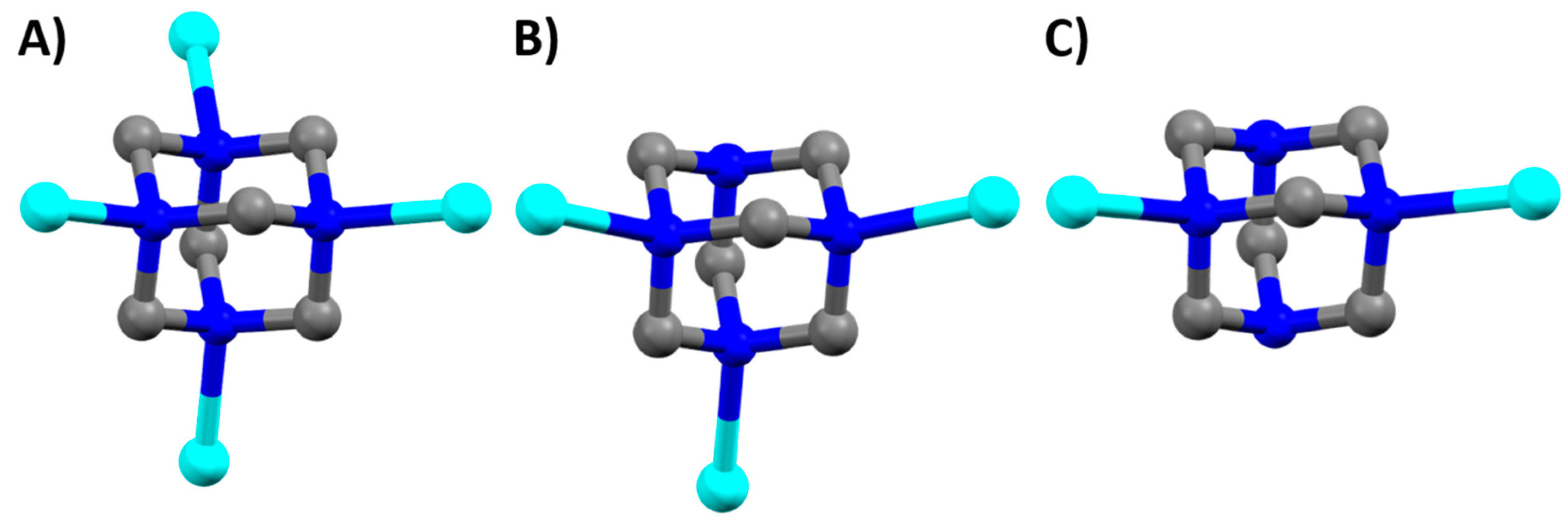
Figure 1.
hmt bridging modes observed in complexes (1–4) shown with the hmt bonded to one copper of the {Cu2(piv)4} unit. (a) μ4 bridging mode observed in complex (1); (b) μ3 bridging mode observed in complexes (2–3); (c) μ2 bridging mode observed in complex (4). Hydrogen atoms removed for clarity.
Figure 1.
hmt bridging modes observed in complexes (1–4) shown with the hmt bonded to one copper of the {Cu2(piv)4} unit. (a) μ4 bridging mode observed in complex (1); (b) μ3 bridging mode observed in complexes (2–3); (c) μ2 bridging mode observed in complex (4). Hydrogen atoms removed for clarity.

Scheme 1.
Acetonitrile hydrolysis reaction (a) and methanol oxidation (b).

Figure 2.
Topological representation of complex (1), tetrahedral hmt nodes shown in pink and linear {Cu2(piv)4} units shown in turquoise.
Figure 2.
Topological representation of complex (1), tetrahedral hmt nodes shown in pink and linear {Cu2(piv)4} units shown in turquoise.
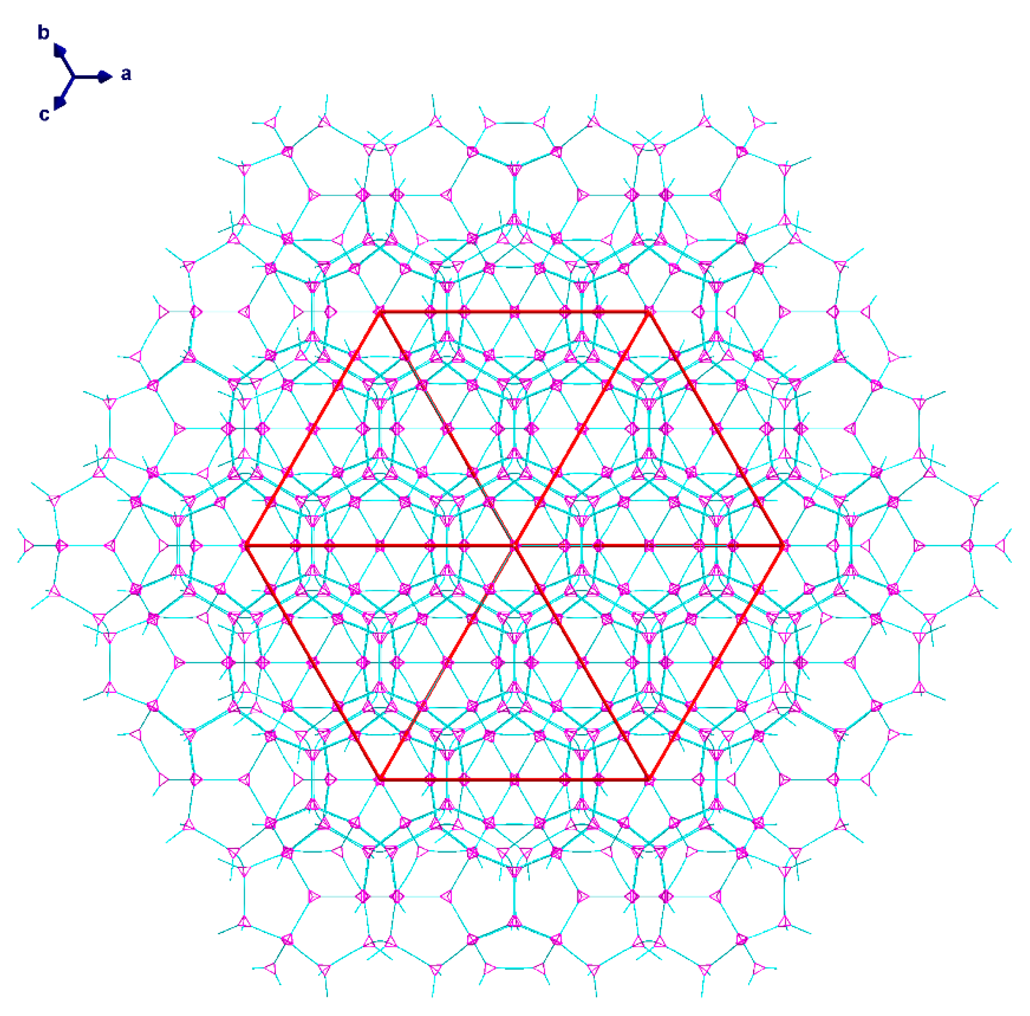
Figure 3.
Topological diagrams of the two cavities present in (1): (a) The 64.512 cavity; (b) the 512 cavity. Tetrahedral hmt nodes shown in pink and linear {Cu2(piv)4} units shown in turquoise.
Figure 3.
Topological diagrams of the two cavities present in (1): (a) The 64.512 cavity; (b) the 512 cavity. Tetrahedral hmt nodes shown in pink and linear {Cu2(piv)4} units shown in turquoise.
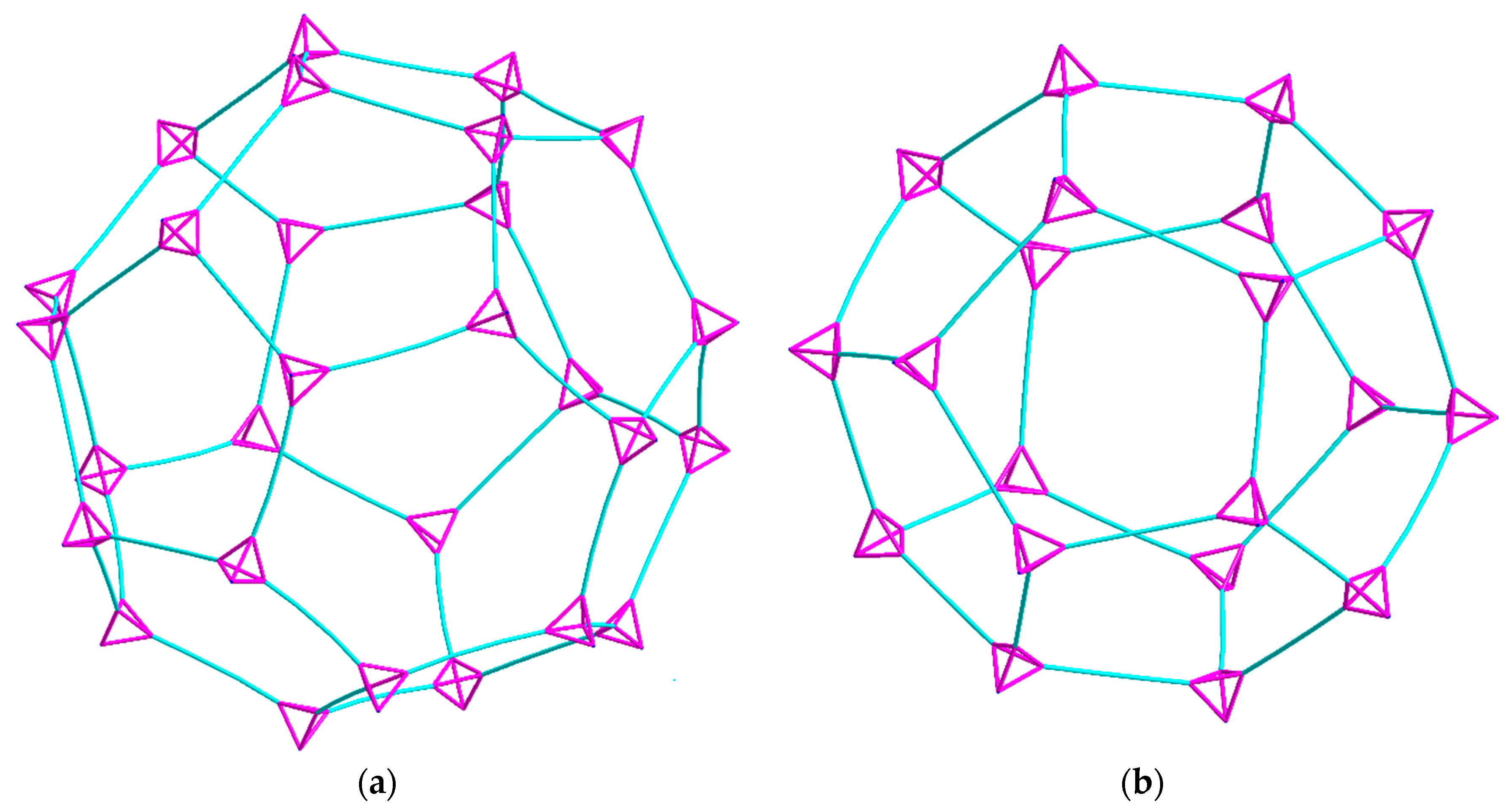
Figure 4.
Space filling models of the hexagonal (a) and pentagonal (b) windows between the cavities present in (1).
Figure 4.
Space filling models of the hexagonal (a) and pentagonal (b) windows between the cavities present in (1).

Figure 5.
Topological diagrams of (2) showing: (a) A ten-membered ring viewed down the a-axis; (b) packing of one network within the unit cell through the c-axis; (c) packing of one network within the unit cell. The yellow and blue linkers represent the helices and the links between them.
Figure 5.
Topological diagrams of (2) showing: (a) A ten-membered ring viewed down the a-axis; (b) packing of one network within the unit cell through the c-axis; (c) packing of one network within the unit cell. The yellow and blue linkers represent the helices and the links between them.

Figure 6.
Topological representation of (2) showing: (a) both networks in a unit cell viewed down the c-axis; (b) with one network deleted also viewed down the c-axis; (c) both networks viewed along the a-axis. The two networks are represented in turquoise and blue colors.
Figure 6.
Topological representation of (2) showing: (a) both networks in a unit cell viewed down the c-axis; (b) with one network deleted also viewed down the c-axis; (c) both networks viewed along the a-axis. The two networks are represented in turquoise and blue colors.
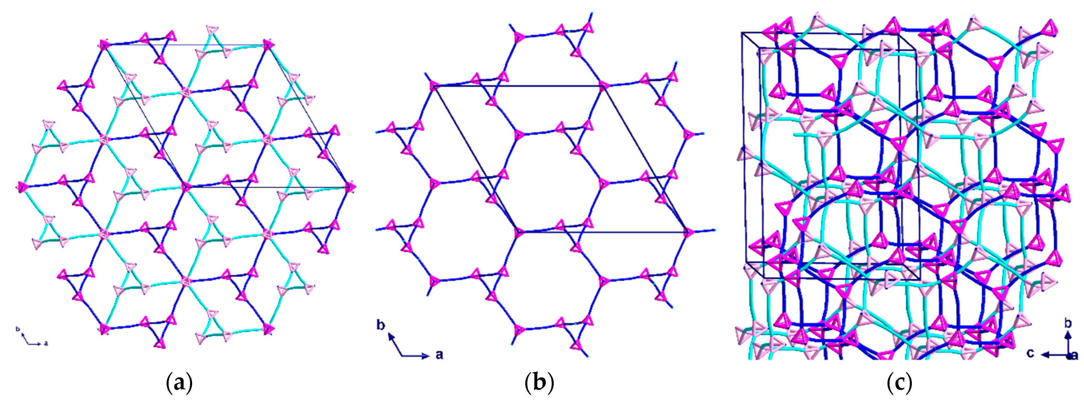
Figure 7.
Topological representation of the two intertwined helices of (3) shown: (a) when viewed along the c-axis; (b) along the a-axis, with double helix graphic added as a guide for the eye. The two networks are represented in turquoise and blue.
Figure 7.
Topological representation of the two intertwined helices of (3) shown: (a) when viewed along the c-axis; (b) along the a-axis, with double helix graphic added as a guide for the eye. The two networks are represented in turquoise and blue.
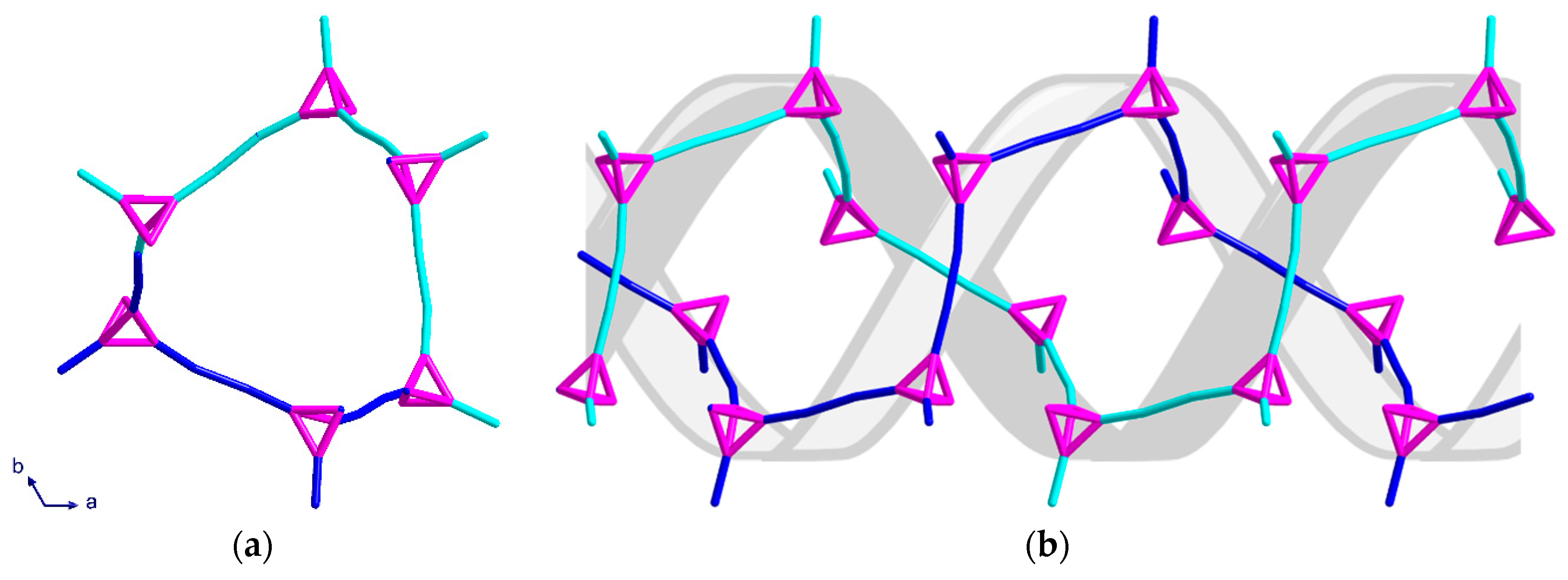
Figure 8.
Topological representation of (3) shown: (a) for one helix when viewed along the b-axis; (b) packing of both networks along the c-axis in a section of four unit cells.
Figure 8.
Topological representation of (3) shown: (a) for one helix when viewed along the b-axis; (b) packing of both networks along the c-axis in a section of four unit cells.
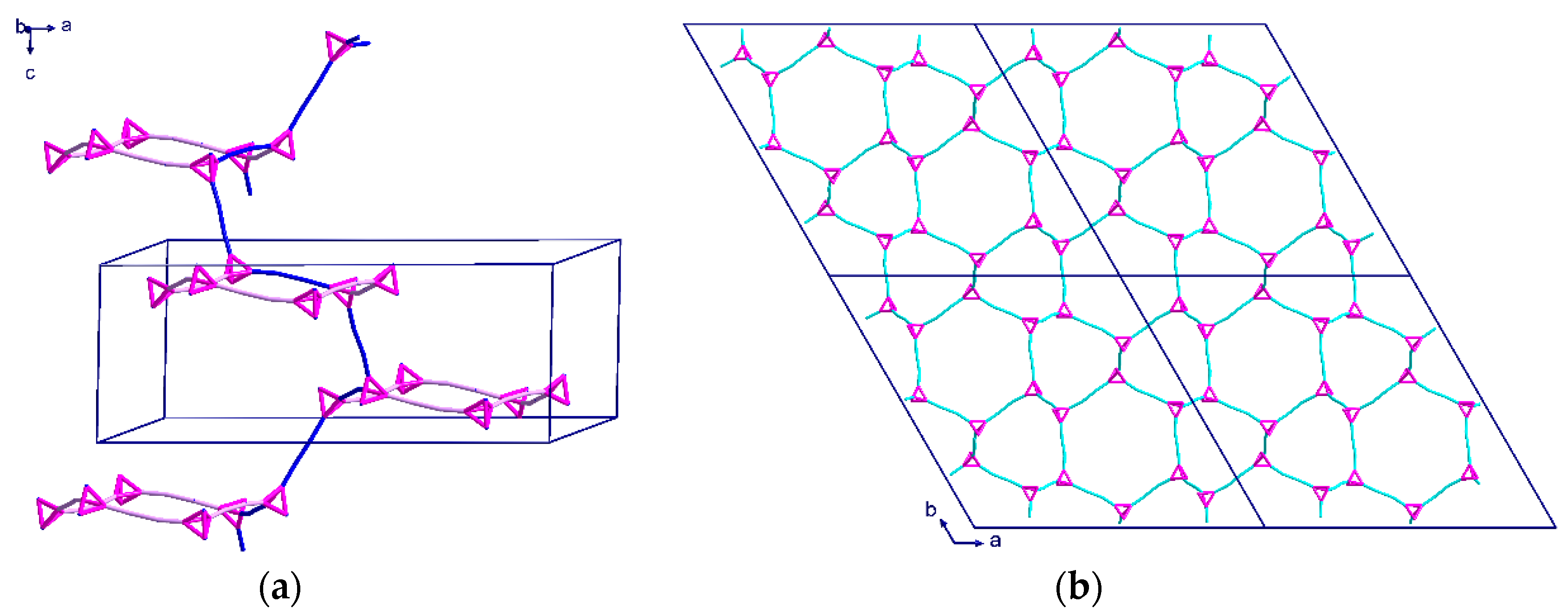
Figure 9.
Topological representation of (4) shown: (a) for one chain when viewed down the a-axis; (b) for one chain viewed down the c axis.
Figure 9.
Topological representation of (4) shown: (a) for one chain when viewed down the a-axis; (b) for one chain viewed down the c axis.

Figure 10.
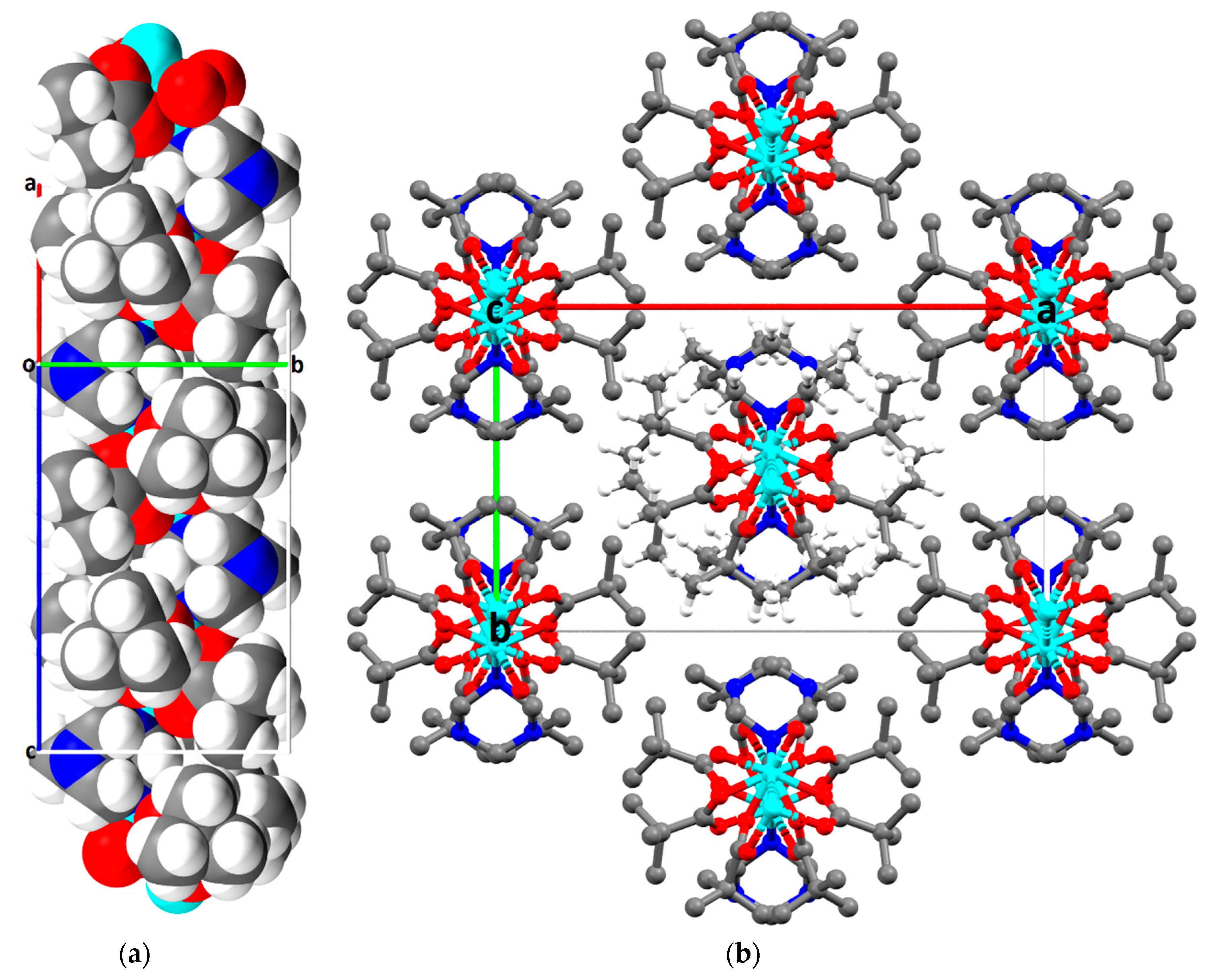
Complex (4) showing: (a) the space filling diagram of three repeating units in a 1D-chain, viewed perpendicular to the c-axis; (b) the close packed arrangement of seven neighboring chains viewed in the ab-plane; hydrogen atoms shown only on the central chain for clarity.
Figure 10.
Complex (4) showing: (a) the space filling diagram of three repeating units in a 1D-chain, viewed perpendicular to the c-axis; (b) the close packed arrangement of seven neighboring chains viewed in the ab-plane; hydrogen atoms shown only on the central chain for clarity.
© 2020 by the authors. Licensee MDPI, Basel, Switzerland. This article is an open access article distributed under the terms and conditions of the Creative Commons Attribution (CC BY) license (http://creativecommons.org/licenses/by/4.0/).
Share and Cite
MDPI and ACS Style
Kühne, I.A.; Carter, A.B.; Kostakis, G.E.; Anson, C.E.; Powell, A.K. Varying the Dimensionality of Cu(II)-Based Coordination Polymers Through Solvent Influence. Crystals 2020, 10, 893. https://doi.org/10.3390/cryst10100893
AMA Style
Kühne IA, Carter AB, Kostakis GE, Anson CE, Powell AK. Varying the Dimensionality of Cu(II)-Based Coordination Polymers Through Solvent Influence. Crystals. 2020; 10(10):893. https://doi.org/10.3390/cryst10100893
Chicago/Turabian StyleKühne, Irina A., Anthony B. Carter, George E. Kostakis, Christopher E. Anson, and Annie K. Powell. 2020. "Varying the Dimensionality of Cu(II)-Based Coordination Polymers Through Solvent Influence" Crystals 10, no. 10: 893. https://doi.org/10.3390/cryst10100893
Note that from the first issue of 2016, this journal uses article numbers instead of page numbers. See further details here.