Article

Numerical Investigation on Dynamic Response of RC T-Beams Strengthened with CFRP under Impact Loading

1
School of Civil Engineering, Liaoning University of Technology, Jinzhou 121001, China
2
College of Engineering, Bohai University, Jinzhou 121001, China
*
Authors to whom correspondence should be addressed.
Crystals 2020, 10(10), 890; https://doi.org/10.3390/cryst10100890
Submission received: 20 August 2020 / Revised: 25 September 2020 / Accepted: 26 September 2020 / Published: 1 October 2020
(This article belongs to the Special Issue Numerical Study of Concrete)

Abstract

:
To precisely evaluate the retrofitting effectiveness of Carbon Fiber Reinforced Plastic (CFRP) sheets on the impact response of reinforced concrete (RC) T-beams, a non-linear finite element model was developed to simulate the structural response of T-beams with CFRP under impact loads. The numerical model was firstly verified by comparing the numerical simulation results with the experimental data, i.e., impact force, reaction force, and mid-span displacement. The strengthening effect of CFRP was analyzed from the section damage evaluation. Then the impact force, mid-span displacement, and failure mode of CFRP-strengthened RC T-beams were studied in comparison with those of un-strengthened T-beams. In addition, the influence of the impact resistance of T-beams strengthened with FRP was investigated in terms of CFRP strengthening mode, CFRP strengthening sizes, CFRP layers and FRP material types. The numerical simulation results indicate that the overall stiffness of the T-beams was improved significantly due to external CFRP strips. Compared with the un-strengthened beam, the maximum mid-span displacement of the CFRP-strengthened beam was reduced by 7.9%. Additionally, the sectional damage factors of the whole span of the CFRP-strengthened beam were reduced to less than 0.3, indicating that the impact resistance of the T-beams was effectively enhanced.

1. Introduction

Reinforced concrete (RC) beams are important load-bearing components in building structures that might be subjected to unexpected impact loads. Compared with the high cost of rebuilding, reinforcing and transforming old structures can bring more beneficial social benefits, the safety and durability of the structure, reduced costs and impact on the surrounding environment, etc. Fiber-reinforced polymer (FRP) materials are an essential and vibrant structural composite material, owing to their high strength, light weight, corrosion resistance, and magnetic resistance properties [1]. Compared with traditional structural reinforcement methods, e.g., stick steel strengthening, increasing the sectional law, concrete replacement, additional fulcrum, and the external prestressing strengthening method, the external FRP reinforcement method is an ideal choice due to its advantages of easy construction and barely increased structural dead weight [2].
Many researchers have carried out studies on the flexural and shearing properties of FRP-strengthened concrete beams under static load [3,4,5,6,7]. In recent years, numerous experimental and numerical studies have been conducted in order to evaluate the effectiveness of FRP reinforcement on the impact resistance performance of RC beams. Tang and Saadatmanesh [8,9] conducted a set of drop hammer tests on external bonding FRP of RC beams and found that the FRP strips could constrain the development of shear cracks and improve their impact resistance. They also found that impact resistance was related to fiber type, thickness, quality and strength. Soleimani et al. [10] investigated a low-speed impact test on 12 RC beams strengthened with jet Glass Fiber Reinforced Plastics (GFRP). The results showed that the beams’ impact resistance could not be improved by increasing the thickness of FRP if they adopted a two-sided bonding reinforcement method. However, increasing the GFRP thickness could increase the beam’s impact resistance if they adopted a U-shaped reinforcement method. Pham and Hao [11,12] successfully studied the influence of the bonding mode of FRP strips and section modification on RC beams’ impact resistance and found that a 45° inclined bonding beam had a higher bearing capacity and deformation resistance than a U-shaped bonding beam. In another study, Liu et al. [13] reported using carbon fiber reinforced plastics (CFRP) to strengthen RC beams without stirrups under static load and impact loading, respectively. FRP could not prevent the shear failure of beams under static load, but could prevent the shear failure of beams under impact load to reach four times of the energy under static load. In terms of numerical simulation, Bhatti and Kishi [14,15] performed an analysis using LS-DYNA to investigate the shear failure behavior of ordinary RC beams and rock shed beams with sand cushion under different impact velocities. Tu et al. [16] compared the concrete damage model (MAT72) in ANSYS/LS-DYNA and the RHT model in AUTODYN, and carried out unit tests on the two models under different pressure conditions. The results showed that MAT72 better conformed to the requirements of simulation accuracy. Meng et al. [17] used the CSCM model in ANSYS/LS-DYNA to simulate the process of axial impact on concrete cylindrical specimens. Then they [18,19] further optimized the model parameters, carried out numerical analysis on reinforced concrete beams under static load and impact load, and the axial impact resistance behavior of cylinder. The default value of software parameters overestimated the plasticity of concrete. Pham and Hao [20] used the 72R3 model of LS-DYNA to simulate RC beam under impact load, and found that boundary conditions had little effect on impact force, but significantly affected its mid-span displacement and failure mode. Zhao et al. [21] proposed the section damage factor to evaluate the damage of RC beams, and used LS-DYNA to study the dynamic response and damage degree of RC beams under impact load with different stirrup spacing, boundary conditions, shape of hammer head, and impact action position.
Although previous studies have made great progress in the dynamic response of FRP strengthened RC members, most of them have mainly been centered on common RC beams. Limited work has been conducted on the impact resistance of T-shaped reinforced concrete beams, especially the strengthening effect of FRP on RC T-beams under impact loads. RC T-beams are widely used in bridges, civil air defense works, and other building structures because of their light weight and fine bending strength. Therefore, in order to precisely evaluate the retrofitting effectiveness of the FRP on the impact response of RC T-beams, in this paper, a series of numerical studies are conducted aiming to study the dynamic behaviors of T-beams strengthened with CFRP patches under the impact loads. Firstly, three-dimensional models of RC T-beams models with CFRP are developed in ANSYS/LS-DYNA and validated with early experimental data. Then the numerical results in terms of the impact force, mid-span displacement and crack development process are compared for the un-strengthened and strengthened T-beams to quantitatively evaluate the strengthening effect of the CFRP sheets. Finally, the effects of different influence factors (e.g., CFRP strengthening mode, CFRP strengthening sizes, CFRP layers and FRP material types) on the impact resistance of FRP-strengthened RC T-beams are comprehensively analyzed.

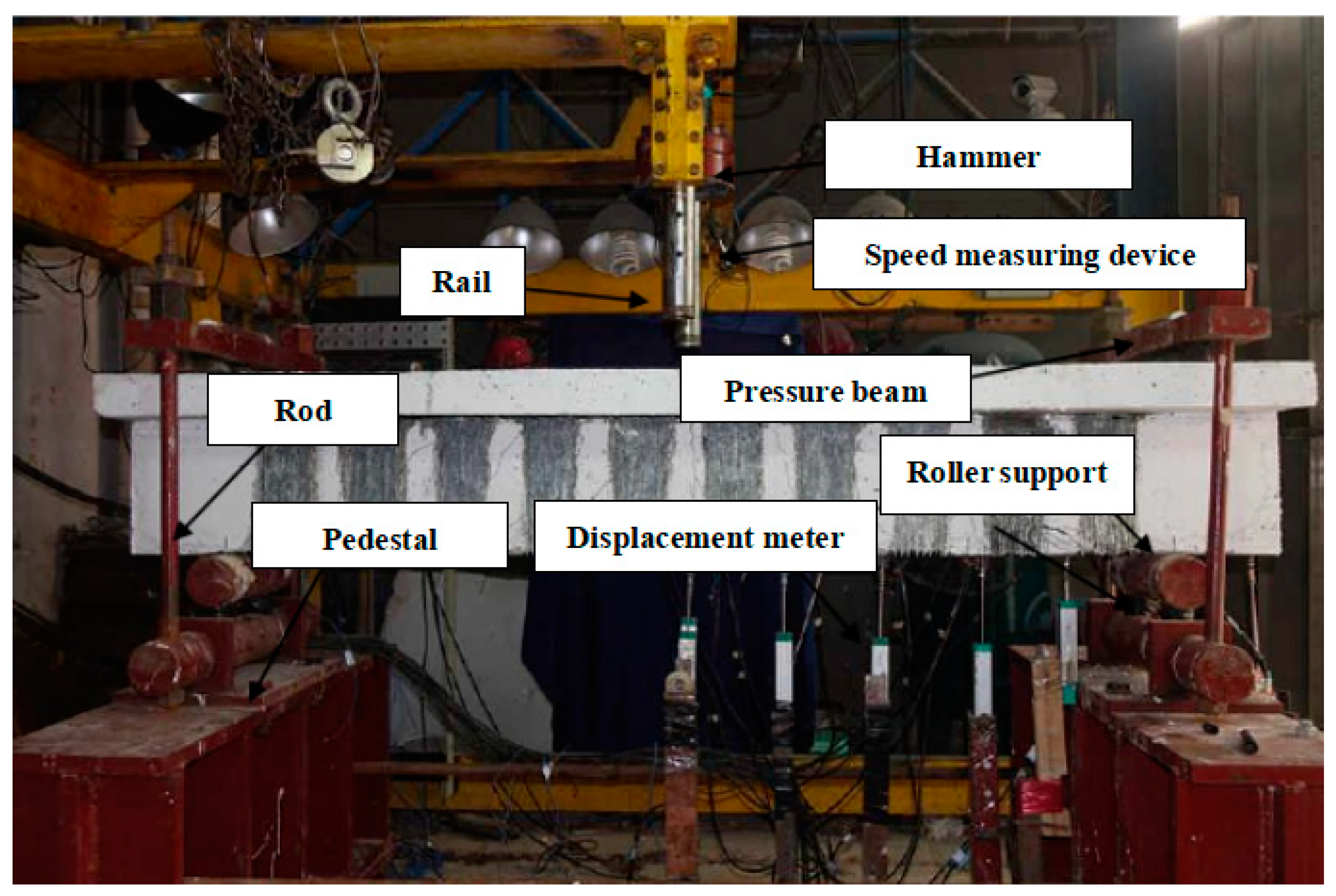
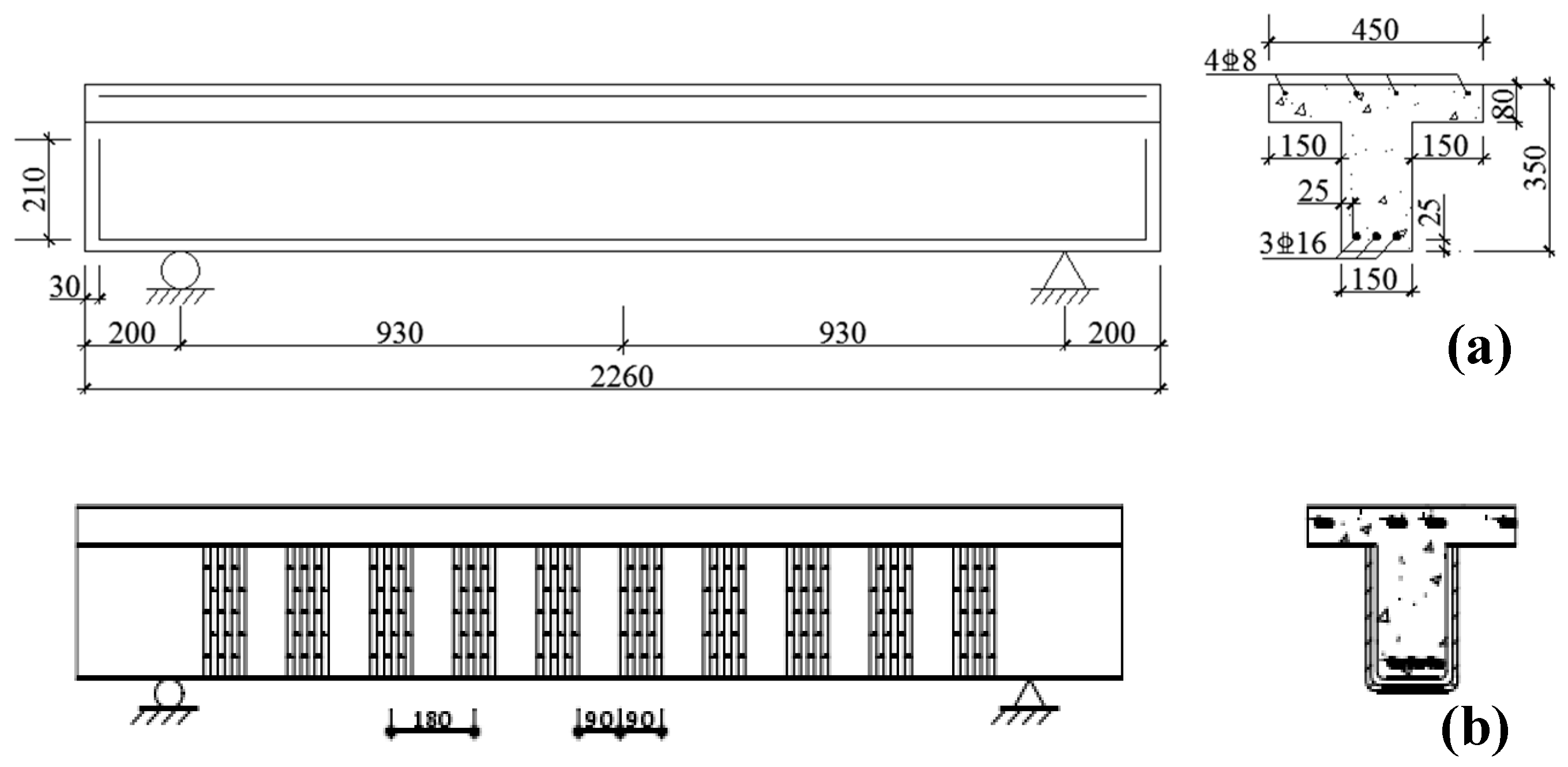
2. Review of the Available Experimental Procedure

This paper was based on the drop hammer impact test conducted by Liu [22]. The dimensions of the CFRP-strengthened T-beam are presented in Figure 1. The CFRP strips were uniformly arranged along the beam span with a width of 90 mm and a spacing of 90 mm. The strength grade of concrete in the specimen was C30, with cylindrical compressive strength was 24.3 MPa, and the concrete cover was 25 mm. The longitudinal reinforcement and auxiliary steel bar were 3D16 and 4D8, with a yield strength of 477.3 MPa and 443 MPa. The drop hammer impact test setup is shown in Figure 2. The hammer head diameter was 200 mm, and the impact position was in the T-beam’s mid-span. The mass of the drop-weight was 296 kg, and the velocity when it impacted was 3780 mm·s−1.

3. Numerical Model of RC T-Beams Strengthened with CFRP

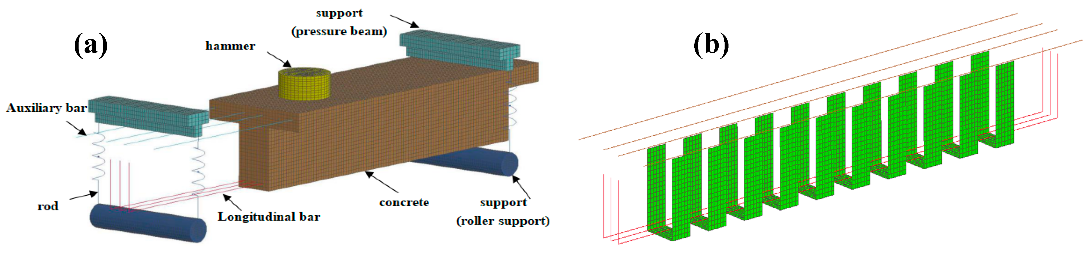
3.1. Finite Element Model

A three-dimensional (3D) elastic plastic finite element (FE) analysis was performed in ANSYS/LS-DYNA. The 3D FE model for the T-beam with CFRP is shown in Figure 3. In the finite element model, the concrete, drop hammer and supports were modeled using 3D solid element (Solid164). The 3D truss element (Link160) was used for longitudinal steel bars and auxiliary steel bars. The spring damping element (Combi165) was used to simulate the rod between the upper and lower supports. CFRP sheet was modeled using thin shell element (Shell163). After convergence verification, there was a total number of 81,958 elements, with 54,360 concrete elements and 1113 steel elements. The structural model mesh sizes were 15 mm. Automatic face-to-face contact was adopted in this paper, in order to model the contact behavior between the beam and the drop hammer, and the beam and supports; a description of the parameters can be found using the Keyword *CONTACT_AUTOMATIC_SURFACE _TO_SURFACE of LS-DYNA. To simplify the calculation, the bond was assumed between concrete and steel bars or CFRP strips by sharing the common nodes, which have been widely used for simulation of the impact resistance of RC structures. Roller support was modeled by constraining the vertical and axial translational freedom of the center axis of lower support, other nodes only constrain in the axial direction, and constrain the axial translational freedom of all upper support nodes in the pressure beam. The impact force can be modeled using the keyword *INITIAL _VELOCITY, where the initial velocity was applied to the hammer.

3.2. Constitutive Model and Material Parameters

The Continuous Surface Cap Model (CSCM) is compared with the other concrete damage model to verify better to simulate the low-speed impact behavior under low confining pressure and low hydrostatic pressure. Therefore, CSCM (MAT_CSCM_CONCRETE) is used to model the dynamic properties of concrete; the theoretical formula of this model is presented in [23]. The specific material parameters of concrete are provided in Table 1. The Nonlinear Plasticity Kinematic Model (MAT_PLASTIC_KINEMATIC) is used to model the steel material. The steel strain rate effect is expressed by the Cowper–Symonds constitutive equation (Equation (1)):
σ 0 σ 0 = 1 + ( ε ˙ C ) 1 p
where σ 0 represents the static flow stress, σ 0 represents the dynamic flow stress when the plastic strain rate is ε ˙ , C and p represent the strain rate parameters, which are 40.4 and 5, respectively, for mild steel [24]. The specific material parameters of steel are provided in Table 2. To save run-time costs during the transit analysis, the hammer is defined as *MAT_RIGID. Linear elastic material (MAT_ELASTIC) is used to model the support, with the elastic modulus and Poisson’s ratio are 2 × 10⁵ MPa and 0.3. The spring-damper element is given by the elastic spring material (MAT_SPRING_ELASTIC), the elastic stiffness is 5 × 10⁴ N/mm. The *MAT_ENHANCED_COMPOSITE_DAMAGE material constitutive model is used to model CFRP sheets. This model can describe arbitrary orthotropic materials and based on Chang–Chang laminate failure criteria [25]. The specific material model parameters of FRP are shown in Table 3 [26,27,28].

4. Validation and Analysis

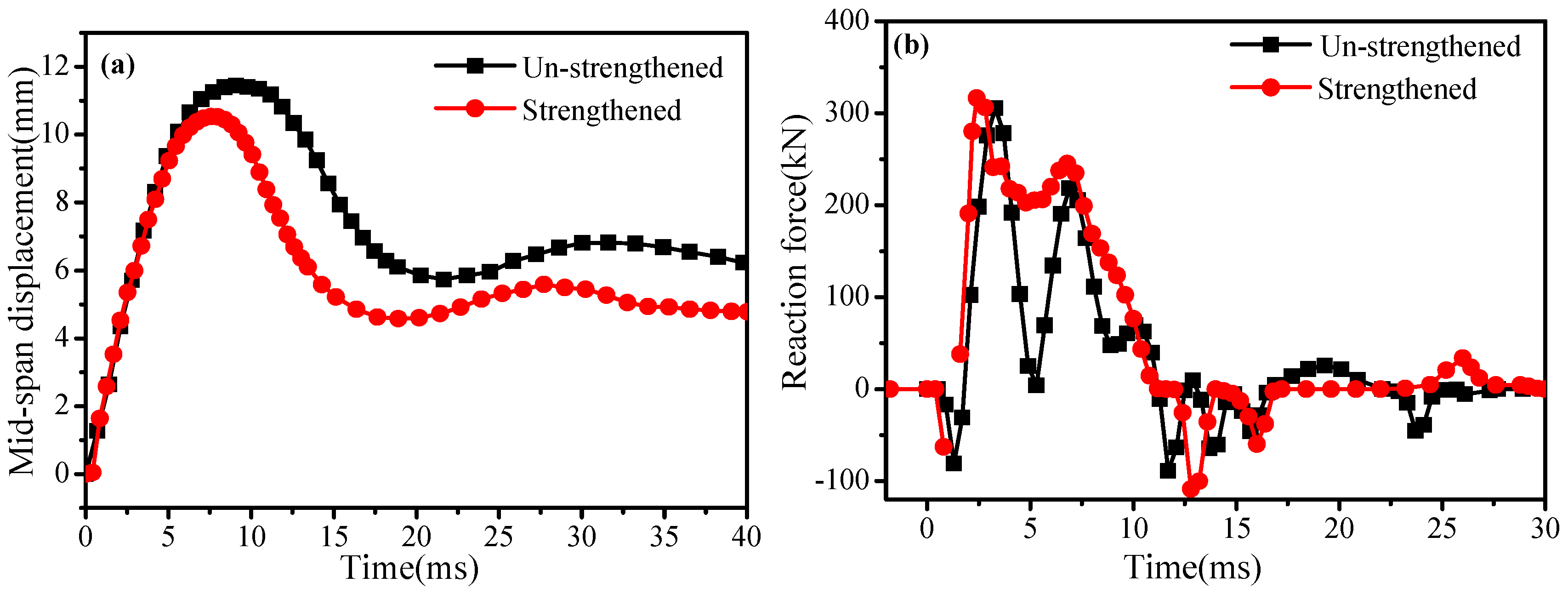
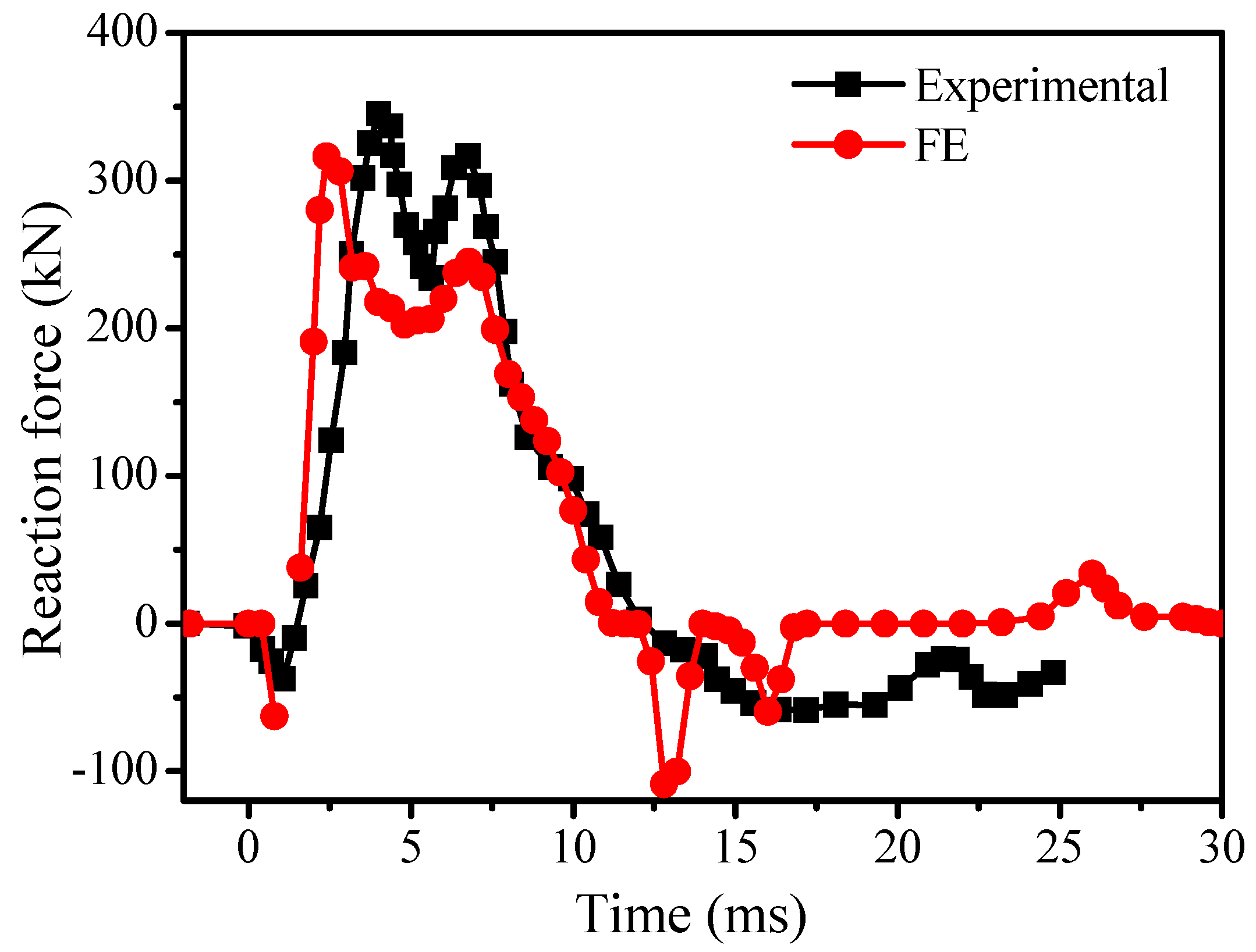
4.1. Impact Force and Reaction Force
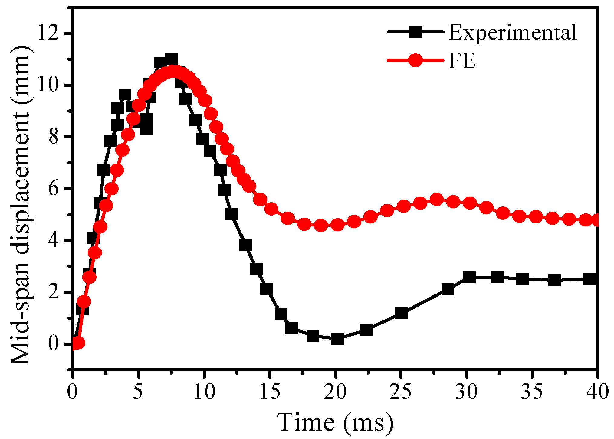
The impact force time history curve of the specimen beams is shown in Figure 4. The impact force peak and the impact duration are consistent between the finite element simulation and the experimental test results. The impact force curve can be divided into three stages: pulse stage, storming stage and recovery stage. In the pulse stage, the impact force rises to a peak steeply and falls rapidly, forming the main peak of impact force, lasting about 1.2 ms. The simulation and experimental results of the maximum impact force are 664 KN and 623 KN, respectively, with a calculation error of 6.6%. Subsequently, several secondary impact force peaks can be obviously found in the shock stage. The maximum mid-span displacement of the specimen can be obtained, and the shock duration is about 14 ms. The impact force drops to zero during the recovery phase. The comparison of numerical simulation and test results of the reaction force for RC T-beams under impact load is shown in Figure 5. The maximum reaction force simulation result of the CFRP-strengthened beam is 316 kN, the test value is 345 kN, and the discrepancy is 8.4%. The numerical results are highly consistent with the experimental results.

4.2. Displacement

The comparison of mid-span displacement obtained from the FE simulation and the experimental test are shown in Figure 6. It can be noted that mid-span displacement time history presents a half-sine wave. This indicates the partial elastic recovery when the displacement achieves maximum, with the dissipated energy that the structural plastic deformation and damage caused residual displacement. The maximum mid-span displacement of the numerical model is 10.54 mm and the maximum mid-span displacement of the test is 10.88 mm. The difference between them is only 3.1%. In summary, the numerical simulation results are in good agreement with the experimental results.

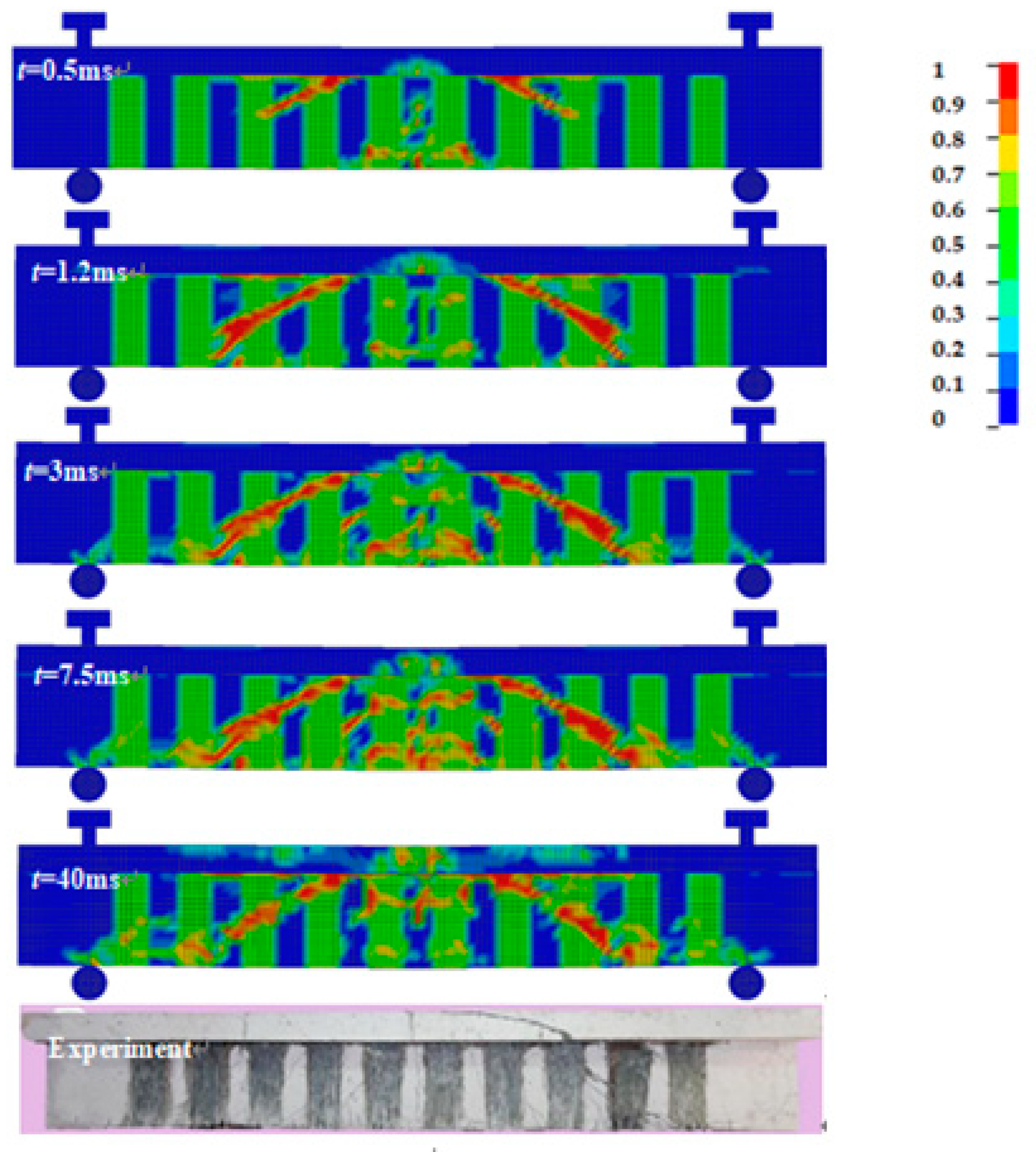
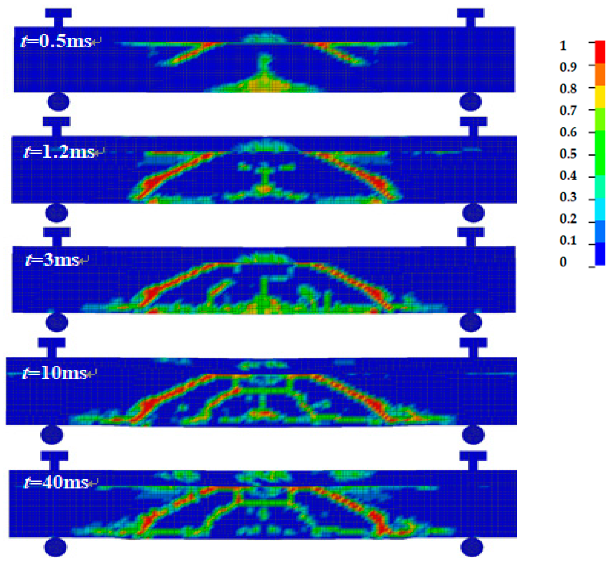
4.3. Fracture Development Process and Failure Mode

The comparison of numerical simulation and test results of failure modes for RC T-beam with CFRP under impact load is shown in Figure 7. The failure mode of the CFRP-strengthened beam is mainly subject to oblique cracks caused by shear force, which shows a typical shear failure mode. When the impact force reaches its peak (0.5 ms), two 45° diagonal cracks appear symmetrically on the beam web. At the end of the pulse phase (1.2 ms), the main oblique crack develops downward to the horizontal height of longitudinal reinforcement. When the impact force reaches its second peak (3 ms), short shear cracks appear at the CFRP strips’ spacing. When the displacement reaches the maximum (7.5 ms), the main change is that the number of small shear cracks between the CFRP strips in the mid-span area increases. At the end of impact (40 ms), some small cracks in the mid-span are closed due to the beam’s rebound. Overall, the simulation model shows a favorable agreement with the test results for the failure mode.
The strain–time history of CFRP is shown in Figure 8. The initial rapid increase of strain of CFRP strips divided by the corresponding time interval was taken as the CFRP average strain rate. In this study, the average strain rate of CFRP is 9 s−1. When the strain rate is less than 10 s−1, the increase of dynamic tensile strength and elastic modulus of CFRP materials is only about 3% [29,30]. Therefore, the influence of strain rate on CFRP is in dynamic debonding or fracture strain [13].

4.4. Section Damage Assessment

The concrete CSCM constitutive model reflects the damage of concrete under impact loads. The damage stress σ i j d is defined as follows:
σ i j d = ( 1 d ) σ i j v p
where d is damage factor; d = 0 is no damage; d =1 is complete damage; and σ i j v p is the no damage stress tensor. Equation (2) expresses the isotropic and proportional reduction of the volume modulus and shear modulus of the material. The failure mode generally shows a limitation of the RC beam structure under impact loads, which has a short acting time and limited area of action. In this study, the damage assessment method [21] is used to determine the most serious damage section in the T-beam, while damage factor ds is the damage factors average value in T-beam cross-section:
d s = 1 n 1 n d
where d is the unit damage factor; n is the sum of section elements. To conveniently and intuitively measure the degree of damage in each section, the section damage factor ds is specified as follows [21], where ds = 0~0.3 is slight damage; ds = 0.3~0.6 is moderate damage; ds = 0.6~0.9 is severe damage; ds = 0.9~1 is component failure.
Figure 9 shows the distribution of section damage factor (ds) along the beam axis of the beam with CFRP, it can reflect that each section impact damage degree and CFRP impact resistance effect. ds is calculated by Equation (3). Overall, the T-beam with CFRP has exhibited a lightly damaged stage and the ds of all sections are below 0.3. In general, the T-beam with CFRP U-wraps can obviously reduce the section damage degree, this confirms an effective mode for improving the structure impact resistance.

5. Parametric Study

From the current literature, it is clear that when external FRP is used to strengthen the structure, e.g., thickness, strength and strengthening mode of FRP play central roles [8,13]. In this paper, the dynamic responses of CFRP-strengthened beams and un-strengthened beams under impact load are analyzed based on impact force, reaction force and crack patterns. To have a deeper understanding of the impact resistance of T-beams strengthened with FRP, different CFRP strengthening modes, CFRP strengthening dimensions, CFRP strengthening layers and FRP material types are used to study the dynamic response of T-beam without stirrup.

5.1. Strengthening Effect of FRP

The displacement of the T-beam with and without CFRP at the mid-span is given in Figure 10a. According to the numerical simulation result, the maximum mid-span displacement and residual displacement of the un-strengthened beam are 11.44 mm and 6.23 mm. Simultaneously, the maximum mid-span displacement and residual displacement of beams with CFRP are reduced by 7.9% and 23.3%, respectively. The reason for this is that the CFRP U-wraps can improve the shear capacity and restrain the shear cracks generated by the T-beam under impact load, thus improving the structural stiffness and reducing the overall deformation [8,22]. Figure 10b shows the reaction force time history for the T-beams with and without CFRP. It can be seen that the maximum reaction force of the CFRP-strengthened beam increases by 3.6% with respect to that of the un-strengthened beam. In addition, the semi-sinusoidal fluctuations of un-strengthened beams are violent and massive compared with the CFRP-strengthened beams. This is consistent with the fluctuation of the reaction force observed in the impact test of CFRP-strengthened and un-strengthened beams [22].
Figure 11 illustrates the crack patterns of the RC T-beam without CFRP. The RC T-beam cracks very quickly on account of there being no stirrup. It can be seen that, similar to the RC T-beam strengthened with CFRP, the damage of the un-strengthened beam was also mainly caused by two 45-degree inclined cracks on the web. However, compared with the beam strengthened with CFRP, the un-strengthened beam’s damage under impact load is more severe. In addition, only one shear crack appears in the span of the un-strengthened beam, but several thin and dense cracks appear in the web of the strengthened beam. This indicates that the CFRP can not only restrain oblique fracture development, but also dissipates the impact of kinetic energy by developing many small cracks, thus improving the impact resistance [22].

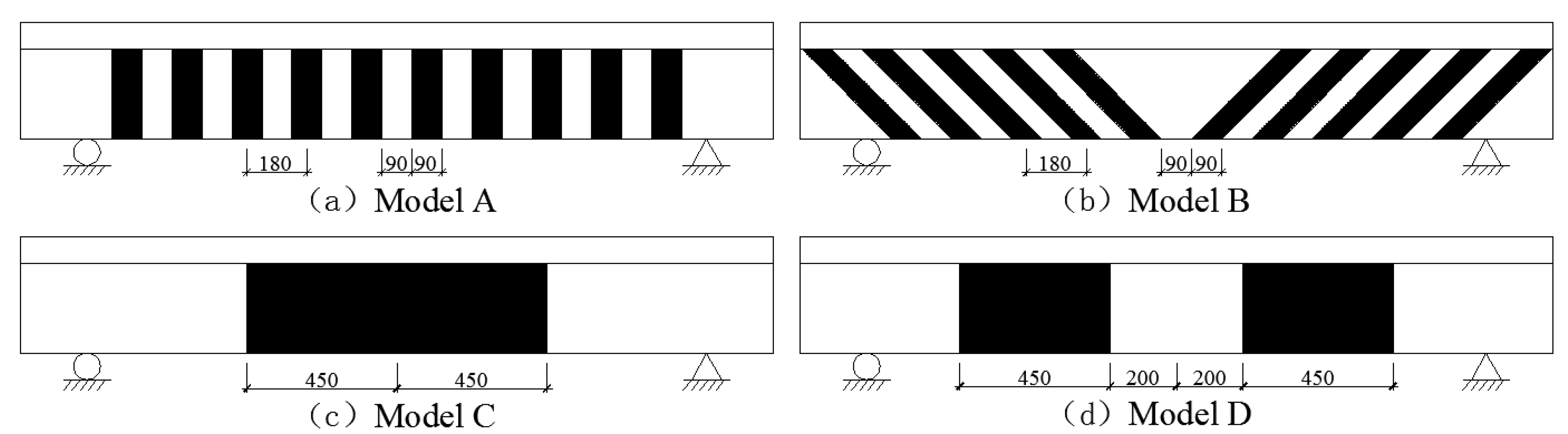
5.2. Effect of Strengthening Modes

In this section, the effect of different U-shaped strengthening modes on the impact response of the T-beam is analyzed. The details of four different FRP strengthening modes (i.e., vertical U-wraps, 45° U-wraps, U-wraps in the mid-span and U-wraps in the shear-span, which are named A, B, C and D, respectively), which are common strengthening techniques, are illustrated in Figure 12. For the four models, the other conditions are all the same.
The mid-span displacement time histories under four CFRP strengthening modes are given in Figure 13. The maximum displacement and residual displacement under different strengthening modes are shown in Table 4. It can be seen that the maximum mid-span displacement for the RC T-beams in the four modes A, B, C and D are 10.54 mm, 8.31 mm, 9.07 mm and 9.49 mm, respectively. Compared with the un-strengthened beam, the maximum mid-span displacement decreased by 7.9%, 27.4%, 20.7% and 17.0%, respectively. Among the four different strengthening types, mode A has the lowest reinforcement effect, while mode B is the highest. The longitudinal tensile strength is about 40 times the transverse tensile strength due to CFRP is an anisotropic material. Therefore, the 45° U-wraps of the fiber strip can reflect the advantages of the high longitudinal tensile strength of CFRP, and this can constrain the development of oblique cracks. The CFRP is perpendicular to the beam axis in the longitudinal direction for reinforcement modes A, C and D, equivalent to adding external stirrups in the reinforcement area [31]; the difference is the additional stirrup position. Therefore, it is observed that the CFRP should be placed in the severe damage section, which can restrain fracture development and reduce impact deformation.

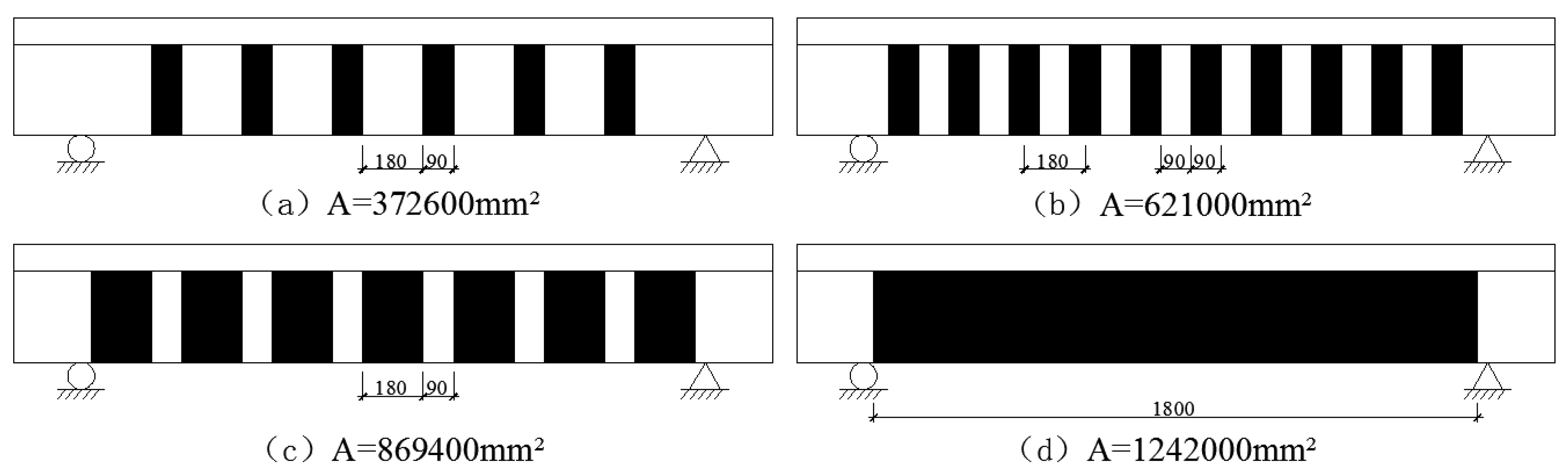
5.3. Effect of Strengthening Sizes

An investigation is performed on the CFRP sizes, which can affect reinforced beams subjected to impact loads. As can be seen in Figure 14, four beams are reinforced with U-shaped CFRP strips, the dimensions of CFRP are 372,600 mm2, 621,000 mm2, 869,400 mm2 and 1,242,000 mm2.
Figure 15 and Table 4 present the dynamic response of different CFRP strengthening sizes of T-beams under impact loads. The mid-span displacement of the strengthened beam decreases with the CFRP size and amount increase. This indicates the CFRP reinforcement has significant advantages in impact resistance. The maximum mid-span displacement and residual displacement of the un-strengthened beam are 11.44 mm and 6.23 mm, respectively. The strengthening sizes of the T-beams are 372,600 mm2, 621,000 mm2, 869,400 mm2 and 1,242,000 mm2; the maximum mid-span displacement decreases by 6.2%, 7.9%, 18.0% and 21.7%, respectively; and the residual displacement decreases by 5.5%, 23.3%, 26.8% and 42.7%, respectively. With the increase of CFRP strengthening size, the stiffness, flexural and shear capacities of the beams increase, the structural deformation reduces.

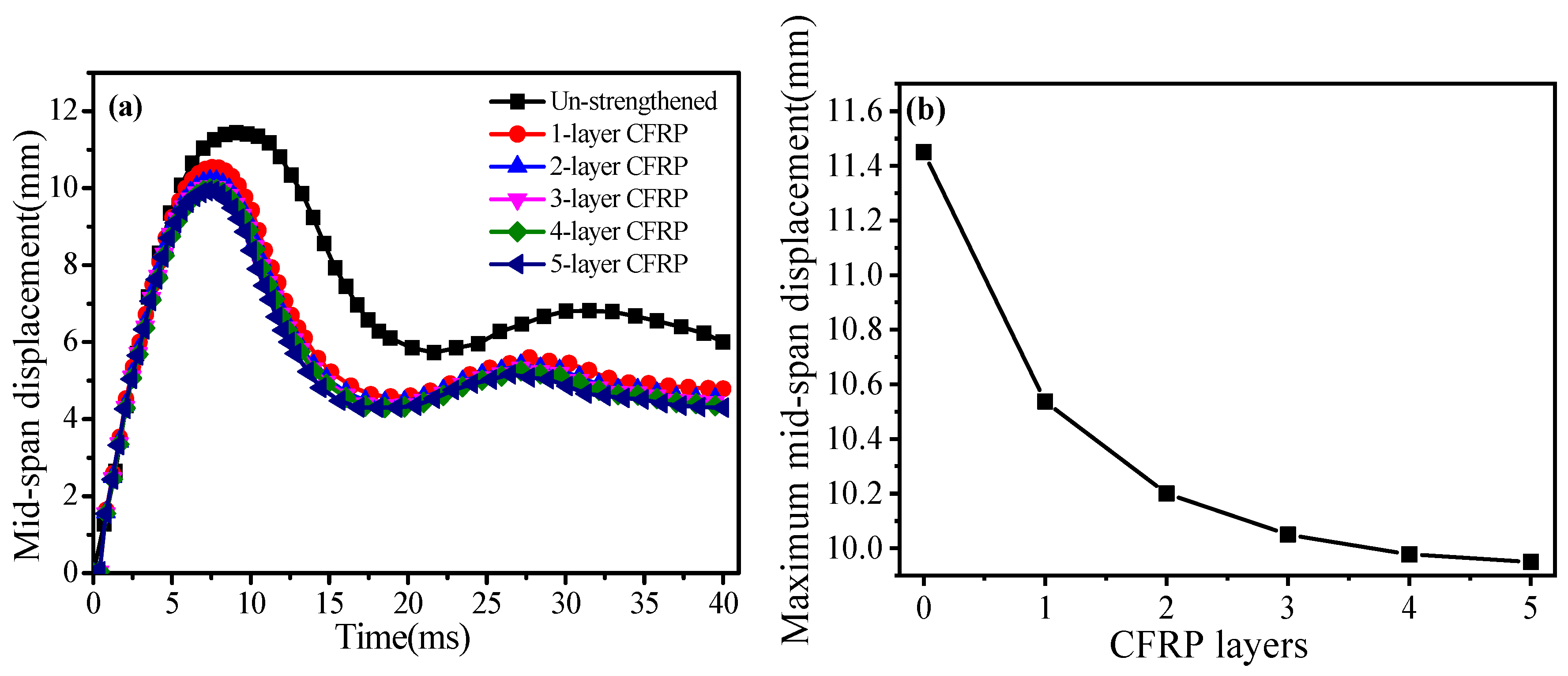
5.4. Effect of Strengthening Layers

The effect of the different CFRP strengthening layers on the impact response of the T-beams is studied in this part. CFRP-strengthened beams with different numbers of layers (1–5-layer), all of which have the same strengthening mode A (size of CFRP is 621,000 mm2), are analyzed.
Figure 16a and Table 4 show the results of the mid-span displacement for beams with different layers. It is found that the maximum mid-span displacement and residual displacement decrease with the increase in CFRP layers. This is attributed to the fact that impact resistance improves with the increase in CFRP layers. However, the increase in CFRP layers is limited in improving the impact resistance. Figure 16b presents the mid-span maximum displacement of T-beams with different CFRP-strengthened layers. It is clear that the mid-span displacement decreases by 4.7% as the number of CFRP layers increases from 1 to 3. Nevertheless, the mid-span displacement only decreases by 0.7% and 0.5% with the increase in layers from 3 to 4 and 5. The main reason for this is that it is difficult for the many layers to work collaboratively. Therefore, by considering the strengthening effectiveness as well as economic considerations, for the strengthened RC beams in this case, the T-beams with 2–3-layer CFRP are adequate for improving the impact resistance.

5.5. Effect of Strengthening Material Types

Considering the high cost of CFRP, other FRP materials can be adopted to strengthen the structure. This study compared the influence of CFRP, Aramid Fiber Reinforced Polymer (AFRP), GFRP on the impact resistance of T-beam. The FRP main mechanical properties parameters are shown in Table 3.
The mid-span displacement of three numerical models with different FRP materials is summarized in Figure 17 and Table 4. As can be seen, the tendencies of the displacement–time histories of the three T-beams strengthened by different FRP are similar. The maximum mid-span displacement and residual displacement of AFRP strengthened beams are 10.88 mm and 4.98 mm, which are 3.2% and 4.2% more than CFRP-strengthened beams. The maximum mid-span displacement and residual displacement of GFRP strengthened beams are 11.01 mm and 5.13 mm, which are increased by 4.5% and 7.3% compare with CFRP-strengthened beams. This indicates that the CFRP is superior to AFRP and GFRP at improving the impact resistance of the RC beam. However, it should be emphasized that the displacement change is within 8%; there is little difference in the reinforcement effect of different FRP materials. In consequence, it is more economical to choose AFRP and GFRP.

6. Conclusions

In this study, ANSYS/LS-DYNA is used to study numerical simulation on the dynamic response of CFRP-strengthened T-beam under impact loads. This paper compared the beams with and without CFRP in terms of mid-span displacement, reaction force and failure mode. Moreover, the effects of CFRP strengthening modes, CFRP strengthening sizes, CFRP strengthening layers and different FRP material types on the impact behavior of RC T-beams were explored. The following can be concluded.
Within the range of 700 mm at the mid-span, it can be observed that all sections ds within the CFRP-strengthened beams are below 0.3 and are slight damage. Therefore, CFRP reinforcement can significantly reduce the beam damage degree under impact loads.
Compared with the un-strengthened beams, the maximum displacement and residual displacement of the CFRP-strengthened beams are reduced by 7.9% and 23.3%, respectively. In addition, the beams with CFRP can dissipate the impact energy by developing small cracks. Thus, CFRP reinforcement enhances the beam impact resistance.
Furthermore, comprehensive parametric studies on FRP-strengthened RC T-beams are carried out by considering various effect parameters under impact loads. It is found for the four different strengthening modes, the strengthened T-beams with 45° U-wraps has the best reinforcement effect. Otherwise, the mid-span displacement of beams decreased with the CFRP sizes increased. Through a set of simulations, the CFRP strengthening layers can improve impact resistance of the beam. However, as the number of CFRP layer increased there was not a proportional decrease in mid-span displacement. Therefore, it is recommended the T-beams with 2-3-layer CFRP are adequate in enhancing the impact resistance. Additionally, compared the influence of CFRP, AFRP and GFRP for T-beam impact resistance, the best reinforcement material is CFRP, AFRP and GFRP are inferior.

Author Contributions

Conceptualization, X.K.; methodology, X.K.; software, H.Z. and Y.G.; validation, X.W.; formal analysis, Y.F.; investigation, H.Z. and Y.G.; resources, Y.F.; data curation, H.Z.; writing—original draft preparation, H.Z.; writing—review and editing, Y.F., Y.G. and X.W.; visualization, Y.G.; supervision, X.K.; project administration, X.K.; funding acquisition, Y.F. All authors have read and agreed to the published version of the manuscript.

Funding

This research was funded by the National Nature Science Foundation of China (51704029) and LiaoNing Revitalization Talents Program (XLYC1807044, XLYC1807050).

Conflicts of Interest

All authors of this article declare no conflicts of interest.

References

  1. Teng, J.G.; Ye, L.P. New Composite Materials and Structures; Science Press: Beijing, China, 2006; Volume 7, pp. 177–192. [Google Scholar]
  2. Zhu, K.J. Experimental Analysis on the Impact Resistance Performance of RC Beams Strengthened with Externally Bonded AFRP Fabric. Master’s Thesis, Henan Polytechnic University, Jiaozuo, China, 2014. [Google Scholar]
  3. Chen, J.F.; Teng, J.G. Shear capacity of FRP-strengthened RC beams: FRP debonding. Constr. Build. Mater. 2003, 17, 27–41. [Google Scholar] [CrossRef]
  4. Deng, Z.G.; Zhang, P.F.; Li, J.H. Fatigue and Static Behaviors of RC Beams Strengthened with Prestressed AFRP. China J. Highw. Transp. 2007, 20, 49–55. [Google Scholar]
  5. Pan, J.L.; Chen, Z.F.; Liang, Z.N. Experimental investigation on flexural and flexural/shear crack induced debonding failure in FRP strengthened concrete beams. J. Southeast Univ. (Nat. Sci. Ed.) 2007, 37, 229–234. [Google Scholar]
  6. Chen, G.M.; Teng, J.G.; Chen, J.F. Process of debonding in RC beams shear-strengthened with FRP U-strips or side strips. Int. J. Solids Struct. 2012, 49, 1266–1282. [Google Scholar] [CrossRef] [Green Version]
  7. Dong, J.; Wang, Q.; Guan, Z. Structural behaviour of RC beams with external flexural and flexural–shear strengthening by FRP sheets. Compos. Part B Eng. 2013, 44, 604–612. [Google Scholar] [CrossRef]
  8. Tang, T.; Saadatmanesh, H. Behavior of concrete beams strengthened with fiber-reinforced polymer laminates under impact loading. J. Compos. Constr. 2003, 209–218. [Google Scholar] [CrossRef]
  9. Saadatmanesh, H.; Tang, T. Analytical and Experimental Studies of Fiber-Reinforced Polymer-Strengthened Concrete Beams Under Impact Loading. ACI Struct. J. 2005, 102, 139–149. [Google Scholar]
  10. Soleimani, S.M.; Banthia, N.; Mindess, S. Sprayed GFRP shear-strengthened reinforced concrete Beams under Impact Loading. Adv. Constr. Mater. 2007, 279–286. [Google Scholar] [CrossRef]
  11. Pham, T.M.; Hao, H. Impact behavior of FRP-strengthened RC beams without stirrups. J. Compos. Constr. 2016, 20, 1–13. [Google Scholar] [CrossRef]
  12. Pham, T.M.; Hao, H. Behavior of fiber-reinforced polymer-strengthened reinforced concrete beams under static and impact loads. Int. J. Prot. Struct. 2017, 8, 3–24. [Google Scholar] [CrossRef]
  13. Liu, T.; Xiao, Y. Impact Behavior of CFRP-Strip-Wrapped RC Beams without Stirrups. J. Compos. Constr. 2017, 21, 37–43. [Google Scholar] [CrossRef]
  14. Bhatti, A.Q.; Kishi, N.; Mikami, H.; Anto, T. Elasto-plastic impact response analysis of shear-failure-type RC beams with shear rebars. Mater. Des. 2009, 30, 502–510. [Google Scholar] [CrossRef]
  15. Bhattia, A.Q.; Kishi, N. Impact response of RC rock-shed girder with sand cushion under falling load. Nucl. Eng. Des. 2010, 240, 2626–2632. [Google Scholar] [CrossRef]
  16. Tu, Z.; Lu, Y. Evaluation of typical concrete material models used in hydrocodes for high dynamic response simulations. Int. J. Impact Eng. 2009, 36, 132–146. [Google Scholar] [CrossRef]
  17. Meng, Y.; Yi, W.J. Dynamic behavior of concrete cylinder specimens under low velocity impact. J. Vib. Shock 2011, 30, 205–210. [Google Scholar]
  18. Meng, Y. Experiment and Numerical Simulation Study on Reinforced Concrete Beam under Impact Loading. Ph.D. Thesis, Hunan University, Changsha, China, 2012. [Google Scholar]
  19. Meng, Y.; Hang, F.L. Numerical simulation study on dynamic behavior of concrete cylinder under drop hammer impact loading. J. Railw. Sci. Eng. 2017, 14, 2427–2434. [Google Scholar]
  20. Pham, T.M.; Hao, H. Plastic hinges and inertia forces in RC beams under impact loads. Int. J. Impact Eng. 2017, 103, 1–11. [Google Scholar] [CrossRef] [Green Version]
  21. Zhao, W.C.; Qian, J.; Zhang, W.N. Performance and damage assessment of reinforced concrete beams under impact loading. Explos. Shock Waves 2019, 39, 111–122. [Google Scholar]
  22. Liu, J.T. Experimental Study on Shear Behavior of RC T Beams without Stirrups Strengthened with CFRP Sheets under Impact Loading. Master’s Thesis, Hunan University, Changsha, China, 2016. [Google Scholar]
  23. Murray, Y.D. Users Manual for LS-DYNA Concrete Material Model 159. Report No. FHWA-HRT-05-062; Federal Highway Administration: McLean, VA, USA, 2007. [Google Scholar]
  24. Zeng, X. Experimental and Numerical Study of Behaviors of RC Beams and Columns under Impact Loadings and Rapid Loadings; Hunan University: Changsha, China, 2014. [Google Scholar]
  25. Zhao, S.Y.; Xue, P. New two-dimensional polynomial failure criteria for composite materials. Adv. Mater. Sci. Eng. 2014, 2014, 1–7. [Google Scholar] [CrossRef] [Green Version]
  26. Yang, L.; Yan, Y.; Kuang, N. Experimental and numerical investigation of aramid fibre reinforced laminates subjected to low velocity impact. Polym. Test. 2013, 32, 1163–1173. [Google Scholar] [CrossRef]
  27. Mou, H.L.; Zhou, T.C.; Feng, Y.F.; Feng, Z.Y. Experiment and Simulation of Composite Corrugated Plate under Quasi-static Crushing and Analysis of Material Model Parameters. Mech. Sci. Technol. Aerosp. Eng. 2015, 34, 618–622. [Google Scholar]
  28. Han, H.; Taheri, F.; Pegg, N.; Lu, Y. A numerical study on the axial crushing response of hybrid pultruded and ±45° braided tubes. Compos. Struct. 2007, 80, 253–264. [Google Scholar] [CrossRef]
  29. Al-Zubaidy, H.; Zhao, X.L.; Al-Mahaidi, R. Mechanical Characterisation of the Dynamic Tensile Properties of CFRP Sheet and Adhesive at Medium Strain Rates. Compos. Struct. 2013, 96, 153–163. [Google Scholar] [CrossRef]
  30. Zhang, X.H.; Hao, H.; Shi, Y.C.; Cui, J.; Zhang, X. Static and Dynamic Material Properties of CFR/Epoxy Laminates. Constr. Build. Mater. 2016, 114, 638–649. [Google Scholar] [CrossRef] [Green Version]
  31. Rodriguez-Nikl, T.; Lee, C.S.; Hegemier, G.A.; Seible, F. Experimental performance of concrete columns with composite jackets under blast loading. J. Struct. Eng. 2012, 138, 81–89. [Google Scholar] [CrossRef] [Green Version]
Figure 1. Details of the tested beam (obtained from Liu [22]). (a) Cross-section size and rebar arrangement. (b) Strengthening details for the beam.
Crystals 10 00890 g001
Figure 2. Drop hammer impact test setup (obtained from Liu [22]).
Crystals 10 00890 g002
Figure 3. 3D finite element model of CFRP-strengthened T-beam. (a) Details of RC T-beam. (b) CFRP U-wraps.
Crystals 10 00890 g003
Figure 4. Comparison of impact force time histories obtained from the FE simulation and experimental test.
Crystals 10 00890 g004
Figure 5. Comparison of reaction force time histories obtained from the FE simulation and experimental test.
Crystals 10 00890 g005
Figure 6. Comparison of mid-span displacement obtained from the FE simulation and the experimental test.
Crystals 10 00890 g006
Figure 7. Failure pattern of RC T-beam with CFRP from test and simulation.
Crystals 10 00890 g007
Figure 8. Strain–time history of CFRP.
Crystals 10 00890 g008
Figure 9. Sectional damage factors of the CFRP-strengthened T-beam.
Crystals 10 00890 g009
Figure 10. Time histories of T-beam with and without CFRP. (a) Mid-span displacement. (b) Reaction force.
Crystals 10 00890 g010
Figure 11. Crack patterns of RC T-beam without CFRP.
Crystals 10 00890 g011
Figure 12. Four kinds of CFRP strengthening modes.
Crystals 10 00890 g012
Figure 13. Mid-span displacement-time histories of T-beams strengthened with different CFRP strengthening modes.
Crystals 10 00890 g013
Figure 14. Four kinds of CFRP strengthening sizes.
Crystals 10 00890 g014
Figure 15. (a) Mid-span displacement-time histories and (b) maximum displacements of T-beams strengthened with different CFRP strengthening sizes.
Crystals 10 00890 g015
Figure 16. (a) Mid-span displacement-time histories and (b) maximum displacements of T-beams strengthened with different CFRP strengthening layers.
Crystals 10 00890 g016
Figure 17. Mid-span displacement-time histories of T-beams strengthened with different FRP material.
Crystals 10 00890 g017
Table 1. The material parameters of concrete.
Density RO
(ton·mm−3)
Calculated Control Parameters
NPLOT
Maximum Strain Increment
INCRE
Strain Rate Switch
IRATE
Unit of Erosion
ERODE
Pressure Recovery Parameter
RECOV
Cap Options
IRETRC
Pre-Damage
PRED
Uniaxial Compressive Strength
f’c (MPa)
Largest Aggregate Diameter
DAGG (mm)
2.4 × 10−91011.40002515
Table 2. The material parameters of steel.
Density RO (ton·mm−3)Elastic Modulus
E (MPa)
Poisson Ratio PR (MPa)Yield
Strength
SIGY (MPa)
Tangent Modulus
ETAN (MPa)
Hardening Parameter
BETA
Strain Rate Parameter
SRC
Strain Rate Parameter
SRP
Failure Strain
FS
7.8 × 10−72 × 1050.34772 × 103040.450.12
Table 3. The material parameters of FRP.
Material ParametersCFRPAFRPGFRP
Density ρ (ton·mm−3)1.53 × 10−91.44 × 10−91.80 × 10⁻⁹
Longitudinal modulus of elasticity Ea (MP)1.28 × 1056.7 × 1043.09 × 104
Transverse modulus for composite Eb (MPa)8.4 × 1034.7 × 1038.3 × 103
Poisson’s ration νba0.02180.02800.0866
In-plane shear modulus Gab (MPa)4.0 × 1032.0 × 1032.8 × 103
Traverse shear modulus Gbc (MPa)4.0 × 1031.586 × 1032.8 × 103
Longitudinal shear modulus Gca (MPa)4.0 × 1031.586 × 1032.8 × 103
Longitudinal compressive strength Xc (MPa)1060312480
Longitudinal tensile strength Xt (MPa)20931420983
Transverse compressive strength Yc (MPa)198145140
Transverse tensile strength Yt (MPa)503640
In-plane shear strength Sc (MPa)1045370
Table 4. Numerical results of strengthened beams with various parameters.
Strengthening ModesFRP Strengthening Sizes (mm2)FRP Strengthening LayersFRP Material TypesMaximum Mid-Pan Displacement (mm)Residual Displacement (mm)
Un-strengthened-0-11.446.23
Model A621,0001CFRP10.544.78
Model B621,0001CFRP8.313.17
Model C621,0001CFRP9.074.55
Model D621,0001CFRP9.494.82
Model A372,6001CFRP10.735.89
Model A869,4001CFRP9.384.56
Model A1,242,0001CFRP8.963.57
Model A621,0002CFRP10.204.53
Model A621,0003CFRP10.054.45
Model A621,0004CFRP9.984.35
Model A621,0005CFRP9.934.30
Model A621,0001AFRP10.884.98
Model A621,0001GFRP11.015.13
Note 1: Model A is the vertical U-shaped reinforcement, Model B is the 45° U-shaped reinforcement, Model C is the U-shaped reinforcement in the mid-span, and Model D is the U-shaped reinforcement in the shear-span. Note 2: Reinforcement size 621,000 mm2, FRP strip 90 mm, spacing 90 mm; Reinforcement size 372,600 mm2, FRP strip 90 mm, spacing 180 mm; Reinforcement size 869,400 mm2, FRP strip 180 mm, spacing 90 mm; Reinforcement size 1,242,000 mm2, no spacing reinforcement.

