Article

Constitutive Modeling of New Synthetic Hybrid Fibers Reinforced Concrete from Experimental Testing in Uniaxial Compression and Tension

by
S. M. Iqbal S. Zainal
1,2,
Farzad Hejazi
1,*,
Farah N. A. Abd. Aziz
1 and
Mohd Saleh Jaafar
1
1
Department of Civil Engineering, Universiti Putra Malaysia, Selangor 43400, Malaysia
2
Department of Civil Engineering, Universiti Malaysia Sabah, Sabah 88400, Malaysia
*
Author to whom correspondence should be addressed.
Crystals 2020, 10(10), 885; https://doi.org/10.3390/cryst10100885
Submission received: 28 July 2020 / Revised: 27 August 2020 / Accepted: 3 September 2020 / Published: 1 October 2020
(This article belongs to the Special Issue Numerical Study of Concrete)

Abstract

:
Hybridization of fibers in concrete yields a variety of applications due to its benefits compared to conventional concrete or concrete with single type-fiber. However, the Finite Element (FE) modeling of these new materials for numerical analyses are very challenging due to the lack of analytical data for these specific materials. Therefore, an attempt has been made to develop Hybrid Fiber Reinforced Concrete (HyFRC) materials with High Range Water-Reducing Admixture (HRWRA) during the concrete mixing process and conduct experimental study to evaluate the behavior of the proposed materials. Constitutive models for each of the materials are formulated to be used as analytical models in numerical analyses. The acquired data are then used to formulate mathematical equations, governing the stress–strain behavior of the proposed HyFRC materials to measure the accuracy of the proposed models. The experimental testing indicated that the Ferro with Ferro mix-combination improved the performance of concrete in the elastic stage while the Ferro with Ultra-Net combination has the highest compressive strain surplus in the plastic stage. In tension, the Ferro with Ferro mix displayed the highest elastic behavior improvement while the Ferro with Ultra-Net designs proved superior in the plastic range, providing additional toughness to conventional concrete.

1. Introduction

Concrete is commonly used in construction because it is economical, easy to procure in the market, and has a wide range of applications. The disadvantage of concrete however is that it is very brittle, which results in poor resistance to crack initiation and propagation as well as low tensile, strain, and low energy absorption capacity. The unreinforced matrices deform elastically under tension until fracture because of the development of micro cracks and localized macro cracking. Fibrous reinforced concrete improves the post-cracking behavior of brittle concrete beyond the elastic stage depending on several factors such as matrix strength, fiber type, fiber orientation, fiber strength, fiber modulus, surface treatment of fibers, fiber aspect ratio, fiber content, and aggregate size [1].
The numerous benefits of using single-fiber reinforced concrete prompted further investigations into combining multiple type of fibers into cementitious composites for improved performance in mechanical properties. The hybridization of polypropylene, natural, glass, asbestos, and carbon fibers in concrete yield positive findings whereby positive synergistic effects were observed between organic and inorganic fibers in improving mechanical properties of concrete [2]. The combination of carbon and steel fibers also showed that steel fibers were effective in increasing strength while carbon fibers improved toughness [3]. Synthetic fibers such as polyethylene and polypropylene were combined and the result proved effective in increasing the performance of concrete in impact loading, flexural strength, as well as toughness. The combination of aluminum, carbon, and polypropylene fibers were studied and has been shown to improve the performance of composites in peak load capacity as compared to polypropylene-only composites [4]. Polyvinyl alcohol fibers and steel fibers were hybridized and the findings showed performance increase of cementitious composites in post-crack behavior [5].
It was also observed that the various length of steel fibers impacted the shrinkage strains of steel, polypropylene, and polyvinyl alcohol hybrid fibers in concrete more profoundly [6]. The combination of steel fiber with polypropylene synthetic fibers were observed to be effective in further enhancing the performance of steel fiber reinforced concrete and ultimate load [7]. The hybridization of steel, Carbon Mesophase Pitch-based (CMP), Carbon Isotropic Pitch-based (CIP), and polypropylene fibers were studied and the findings showed that CIP HyFRC (Hybrid Fiber Reinforced Concrete) produced higher performance than CMP hybrid counterpart [8]. The various forms of polypropylene fibers were examined in concrete and the findings discovered were that fibrillated polypropylene fibers were more effective compared to its monofilament counterpart in reducing plastic shrinkage cracks [9]. Additionally, it has been studied that the use of synthetic polyvinyl alcohol and recycled polyethylene terephthalate (PET) fibers significantly improved the mechanical properties of Strain-Hardening Cementitious Composite (SHCC) even when 50% of the polyvinyl alcohol fibers were replaced by the recycled PET fibers [10].
The combination between different types of synthetics were studied from a polypropylene-polyethylene fiber hybrid and the test results modified the failure behavior of concrete by effectively distributing the loads [11]. The various forms of steel fibers and polypropylene fiber hybrids were investigated and the combination showed that the anchorage and length of fibers do not provide significant improvement from each other but materials do, as shown in the effectiveness of using steel fibers [12]. It was discovered that the shear capabilities of concrete were improved with the addition of polypropylene and polyethylene fibers and changed its mode of failure without stirrups from brittle to ductile [13]. The structural application of steel and polypropylene fibers were tested and it was observed that polypropylene fibers produced better damage mitigation performance due to its higher deformation capacity compared to steel fibers [14]. The use of specially selected polyethylene fibers improved the strain hardening of cementitious composites with the tensile capacity averaging up to 8% [15].
In addition, further tests were conducted using polypropylene fibers and the findings showed that fibrillated polypropylene fibers minimized more damage and permits serviceability to the structure tested [16]. The use of recycled PET synthetic fibers were experimentally tested and the results highlighted significant improvement in compression and flexural enhancement for the case of low-strength concretes [17]. Furthermore, the bridging effect of HyFRC steel and polypropylene fibers enhanced the bond stress of rebar [18]. The use of polypropylene, polyethylene, and polyvinyl alcohol synthetic fibers have been shown to improve the mechanical properties of cementitious composites and the key fiber parameters have been identified [19]. The investigation on the tensile behavior of high-strength strain-hardening cement-based composites (HS-SHCC) using high density polypropylene, aramid, poly(p-phenylene-2,6-benzobisoxazole) (PBO), and high density-PBO fibers were conducted and the results exhibited promising improvements [20].
It can be deduced that the use of fibrous concrete improved the overall mechanical properties of concrete which then correlates to the increased lifecycle of a structure. However, the rheological properties of the HyFRC in the reviews were seldom disclosed and fibers were known to deteriorate fresh concrete workability. Hence a parametric study using HRWRA (High Range Water-Reducing Admixture) was conducted in this research to observe and assess the effect of the admixture on the behavior of the HyFRC so that a standardized mixing guideline can be established for future applications on the proposed materials.
Conjointly, conducting numerical analyses for unconventional materials proved challenging as most commercial FE (Finite Element) software material libraries are constrained to conventional concrete. Most of the studies that have been conducted in the reviews performed small-scale experimental testing in compression, tension, and flexure while large-scale tests were narrowed to using steel fibers hybrid combinations as it has higher chances of obtaining favorable results, thus lowering the cost of experimental testing. This poses a problem as combination of other types of fibers in large-scale tests were limited to steel fiber hybrids due to the possible risk of unfavorable or mediocre results. Hence this paper attempts to develop non-steel HyFRC synthetic fiber combinations and formulate constitutive modelling of these materials for FE modelling and numerical analyses. This would lower costs of experimental testing while broadening the opportunity of these materials to be numerically tested in various structural applications, unconstrained by overhead costs.

2. Proposed Synthetic Hybrid Fiber Reinforced Concrete

A study is conducted in this paper to develop different types of synthetic fiber combinations in cementitious composites and reduce the reliance of steel fibers as primary fibers in any hybridization mixes. This is because synthetic fibers are more economical than steel fiber and provide similar performance to a certain degree [21]. Additionally, the non-corrosive nature of synthetics proved advantageous as corroding steel fibers deteriorate the performance of concrete. It was also proven that the production of synthetics reduce the carbon footprint more than steel [22]. The workability problems of fresh concrete associated with fibrous concrete would be addressed in the admixture parametric study.
The proposed Hybrid Fiber Reinforced Concrete is made up of concrete and synthetic fibers from FORTA Corporation (Grove City, PA, USA), namely the Ferro macrofiber as the primary fiber and the Ultra-Net, Super-Net, Econo-Net, and Nylo-Mono microfibers as the secondary fiber in the combination mix-design. All of the fibers have varying mechanical properties, bonding power, manufactured form, materials, and fiber volume fraction used as shown in Table 1. A total of five hybrid mix-designs were proposed with one plain concrete as the controlled specimen. The volume fraction of fibers used and designations for the proposed materials are shown in Table 2. The range of the fiber volume fractions were defined based on a previously conducted study on fiber hybridization [23]. Normal-mix concrete was used to design the concrete as follows; cement = 409 kg/m3; water = 225 kg/m3; sand = 836 kg/m3; 10 mm coarse aggregates = 302 kg/m3; 20 mm coarse aggregates = 604 kg/m3. Portland cement Type II was used with the following properties, specific gravity = 3.15; chemical composition = tricalcium silicate (3CaO·SiO2), dicalcium silicate (2CaO·SiO2), tetra-calcium aluminoferrite (4CaO·Al2O3Fe2O3); particle size distribution = 1.2 µm (D5%), 18 µm (D50%), 67 µm (D95%). A pan type concrete mixer was used during concrete mixing with a rotational speed of 15 rpm. Subsequently, 24 cylindrical and dog-bone specimens were casted and demolded after 24 h. All of the specimens were cured for 28-days in a water tank prior to the uniaxial testing in compression and tension.

3. Experimental Program

The experimental program is divided into three phases. The first phase is the admixture parametric study, with the aim to investigate the effect of using a HRWRA on the slump workability, compressive, and tensile strength of the proposed HyFRC. After standardized mix-guidelines were established from this study, cylindrical and dog-bone specimens were casted from the standard mix guide to be tested under uniaxial compressive and tensile tests for constitutive modeling.

3.1. Admixture Parametric Study

A study on the effect of HRWRA on the selected five HyFRC designs were conducted using ADVA Cast 512 polymer-based HRWRA from GCP Applied Technologies (Cambridge, MA, USA). The HRWRA complies with the Standards Specification of Chemical Admixtures for Concrete [24] and is categorized under Type F, with the purpose of water-reducing, high-range, and accelerating admixtures. The Guide for the Use of High-Range Water-Reducing Admixtures (HRWRAs) in Concrete [25] was followed during the tests. Trial mixes were conducted to obtain a HRWRA optimum dosage for each HyFRC based on the workability test of fresh concrete as well as compressive and tensile tests of hardened concrete. Table 3 lists all the HRWRA dosages used for the trial mixes. The dosage rate was determined from the mass of cement.
The workability tests were carried out according to the Standard Test Method for Slump of Hydraulic-Cement Concrete [26]. Wet HyFRC was poured into the mold at one third of its volume for three times, with each layer stroked 25 times. The mold was then removed, followed by the measurement of the vertical difference between the top of the mold and the displaced wet concrete.
The compressive strength of the HyFRC was evaluated in adherence to the Complementary British Standard to BE EN 206: Specification for constituent materials and concrete [27]. A total of thirty-six 100 mm cubes were casted, water-cured, and tested at 28-days using a Universal Testing Machine (UTM). The UTM has a maximum capacity of 5000 kN and the loading rate was defined at 6 kN/s. The equation used to determine the compressive strength is shown below:
Compressive   Strength   ( MPa ) = P A
whereby P denotes the maximum load obtained from the UTM (N) while A is the cross-sectional area of the cube (mm2).
The tensile strength of the HyFRC was determined using the Standard Test Method for Splitting Tensile Strength of Cylindrical Concrete Specimens [28]. A total of thirty-six 100 × 200 mm cylinders were cured for 28-days and split-tested using a 5000 kN Universal Testing Machine (UTM) at a configured loading rate of 1.57 kN/s. The splitting tensile strength is calculated as follows:
T = 2 P π ld .
whereby T is the splitting tensile strength (MPa) and P is the maximum load from the UTM (N). l is the length and d is the diameter of cylinder (mm).

3.2. Uniaxial Compression Test

The uniaxial compressive behavior of the HyFRC was tested using a modified set up from the Standard Test Method for Static Modulus of Elasticity and Poisson’s Ratio of Concrete in Compression [29]. The improvised arrangement was taken from a previous study [30] and shown in Figure 1. A total of twelve 150 × 300 mm cylinders were prepared and tested for compression using a 2000 kN UTM machine, with a loading rate of 0.02 mm/s. Two 50 mm Linear Variable Displacement Transducers (LVDT) were clamped on a circular jig around the cylinder to measure the compressive load in the elastic stage while two other 100 mm LVDTs were placed parallel to the cross-head movement of the test machine to record the load during the plastic stage.
The Concrete Damaged Plasticity (CDP) models were determined using the relationship between the damage parameters and the compressive strength of respective HyFRC via the plastic hardening strain ε c p l , h . The equations governing the compressive characteristics are shown as follows:
σ c = ( 1 d c ) E 0   ( ε c ε c p l , h )
{ ε c i n , h = ε c σ c E 0 ε c p l , h = ε c σ c E 0 ( 1 1 d c )
ε c p l , h = ε c i n , h d c 1 d c σ c E 0
In addition, this study uses the parabolic constitutive model developed by Kent and Park [31] for unconfined concrete, which is generally expressed by the equation:
σ c = σ c u [ 2   ( ε c ε ´ c ) ( ε c ε ´ c ) 2 ]
whereby nominal compressive stress and strain are shown as σ c and ε c while the ultimate compressive strength and strain are represented as σ c u and ε ´ c . The value of ε ´ c was defined at 0.002 in this study as has been previously reported by Park [32].
The illustration of the model is shown in Figure 2a. The curve exhibited from point A to B shows the hardening stage of concrete while the linear behavior from point B to C displays the strain-softening state for both confined and unconfined concrete. The softening phase continued until 20% of the unconfined cylinder compressive strength at point C—achieving a plastic behavior from point C to D onwards. For simplicity, the constitutive model was considered to be a parabolic curve. Equation (6) assumed a nonlinear behavior such that the constitutive model came into effect when the compressive strength was 60% of the total strength. The elastic modulus was defined up to 40% of the concrete’s strength in the elastic phase. Subsequently, the inelastic strain hardening in compression was derived as shown below:
ε c i n , h = ε c σ c E 0
The inelastic strain hardening in compression ε c i n , h controls the unloading curve of the concrete in compression, which is an effective parameter in defining damage in compression d c . Given that the ε c i n , h has a direct correlation with d c , the following equation can be expressed:
d c = 1 σ c σ c u
From Figure 2b, it can be observed that the tangent of the curve declined with respect to the modulus of elasticity E 0 . This is as a result of the damage from an inclining plasting strain of brittle materials. The damage parameters d c was 0 at the maximum point and decreases up to 0.8—which was 20% of the remaining strength in large strains.

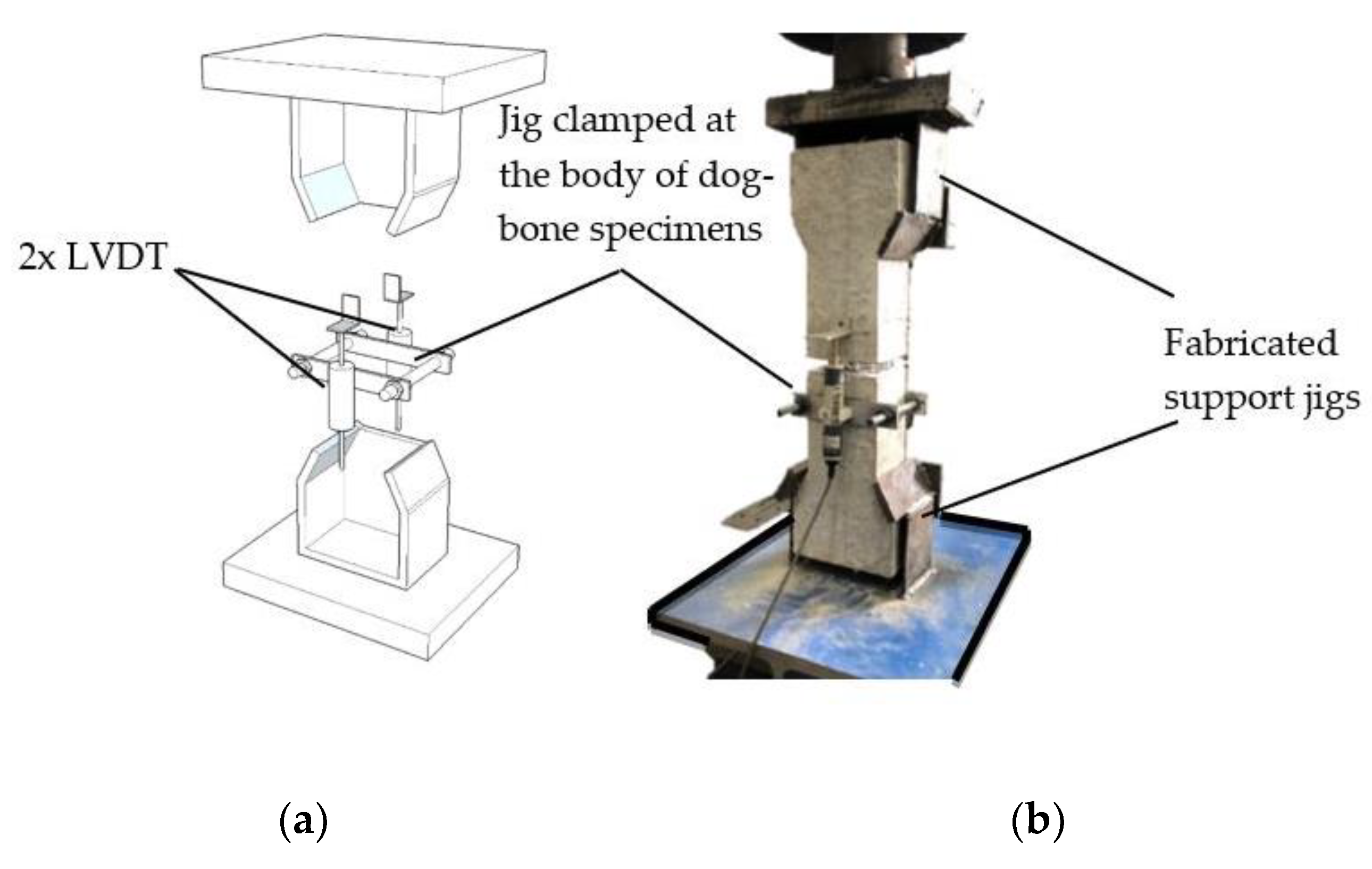
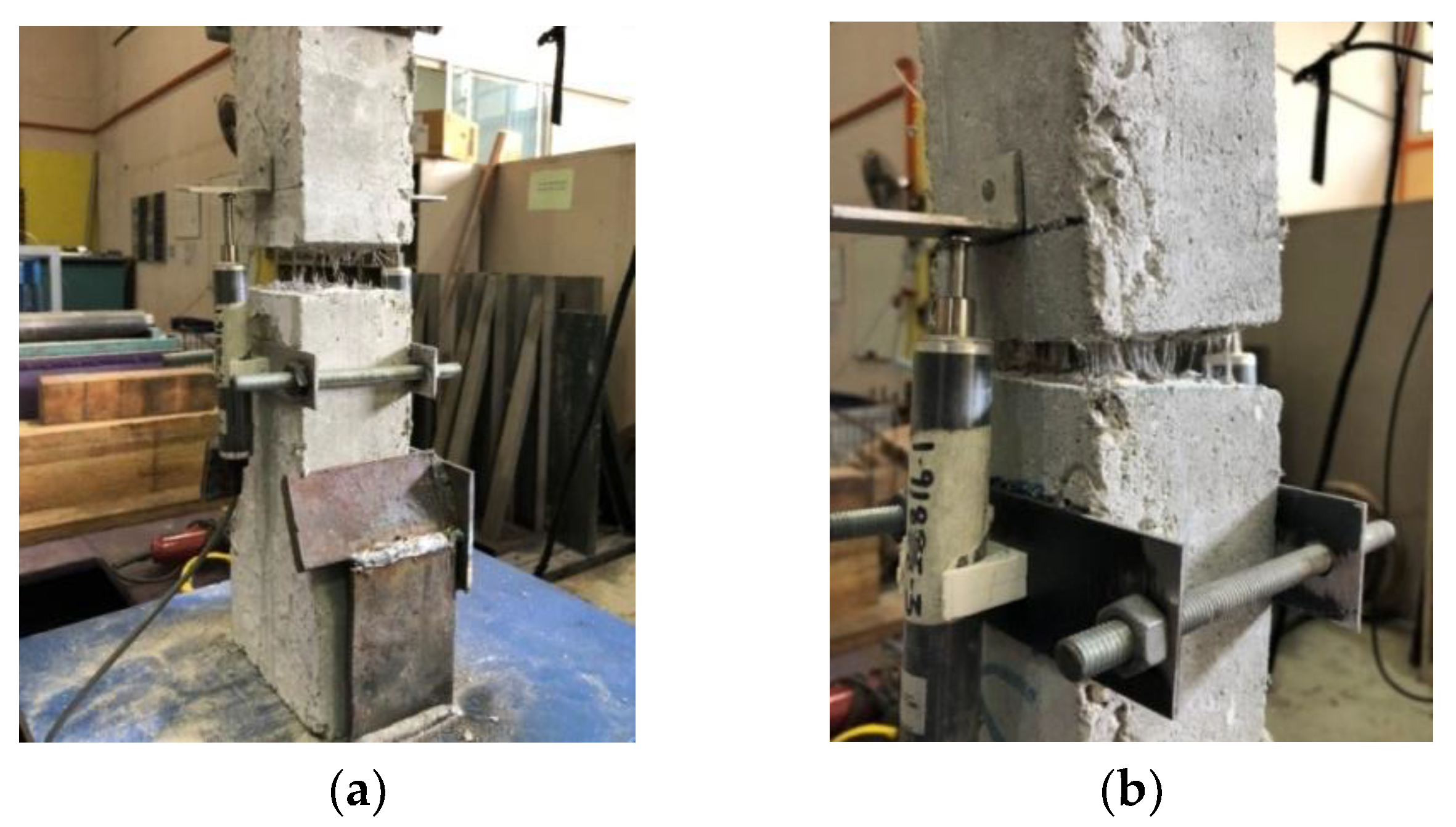
3.3. Uniaxial Direct Tensile Test

The uniaxial tensile tests were conducted using the proposed set up by a previous study [30] using a 250 kN UTM with added support jigs welded to the plates for the dog-bone specimens, as shown in Figure 3. The loading rate was configured at 0.07 mm/s and a total of 12 dog-bone specimens were prepared with a length of 500 mm and a 120 × 80 mm base which changes to a prismatic shape of 80 × 80 mm. A 10 mm-deep notch was sawed across the middle-section of the prism to define the cracking plane and two 25 mm LVDTs were clamped on the specimen, near the notch-area, to record the tensile deflections. The calculations to extract the required tensile data were referred from the Recommendations for Design and Construction of High Performance Fiber Reinforced Cement Composites with Multiple Fine Cracks (HPFRCC) [34].
There are numerous constitutive models developed for concrete in the tension, however, most research deemed it insignificant due to the minimal differences between each model. Concrete in general is brittle in tension and is mostly supported with steel reinforcements. Hence in numerical modelling, the tensile behavior is simplified with more focus directed on the interaction between concrete and the embedded steel reinforcements. Hence, for simplicity, the plasticity hardening strain in tension ε t p l , h was derived from the equations below:
σ t = ( 1 d t ) E 0   ( ε t ε t p l , h )
{ ε c c k , h = ε t σ t E 0 ε c p l , h = ε t σ t E 0 ( 1 1 d t )
ε c p l , h = ε c c k , h d t 1 d t σ t E 0
The models used 7–10% of maximum compressive strength σ c u as tensile strength σ t 0 such that the maximum value can be represented as σ t 0 = 0.1 σ c u . This study applies 1% of the tensile strength during analysis regardless of the actual condition to avoid instability during the numerical analyses. In addition, the corresponding strain value was taken as 10 times the percentage of the strain whereby stress was equal to ultimate tensile strength. From Figure 2c, a direct correlation can be established with the hardening cracking strain and the tensile damage—as the cracking strain increased, so does the tensile damage. This could be expressed as below:
d t = 1 σ t σ t 0

4. Results and Discussion

4.1. Admixture Rheological Impact

The effect of using ADVA Cast 512 polymer-based High Range Water-Reducing Admixture (HRWRA) on the developed HyFRC was studied to improve the workability as well as the corresponding compressive and tensile strengths. Each of the different type of fibers used in this study were selected mainly the FFC, F6U3, F6S3, F6E3, and F6N3 to test and observe the fiber combination efficacy.
As indicated in Table 4, the slump parametric study for the FFC was conducted at 0.2% dosage, however, the results showed poor workability up until the 0.4% dosage rate where the first slump was recorded. Subsequently, both the F6U3 and F6S3 were tested with the 0.4% baseline but recorded zero slump, even at a 0.6% dosage rate. Good workability behavior was only observed at 0.7–1.0% dosage rate—however concrete bleeding effect was observed at this maximum range. Therefore, a 0.8% threshold limit was imposed to avoid this effect, which may influence the corresponding compressive and tensile strengths of the HyFRC. In the case for the F6E3 and F6N3, both the hybrids only indicated slump values when more than 0.6% HRWRA dosage was applied.
The average slump results observed in Figure 4a showed that the FFC and F6E3 design require 0.6% admixture dosage or less to obtain slump while the F6U3, F6S3, and F6N3 require more than 0.6% to achieve a workable state. For the purpose of simplicity, the admixture dosage rates in this study are classified into three levels—low, moderate, and high. Low levels require less than 0.6% dosage (<0.6%), moderate at 0.6% (=0.6%), and high, which demands HRWRA dosage more than 0.6% (>0.6%). These classifications are further discussed as below:
1.
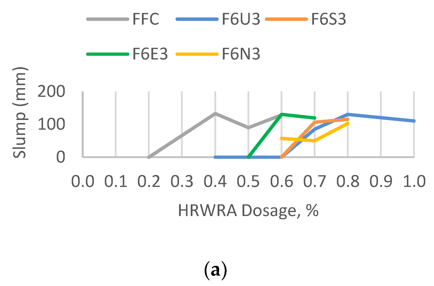
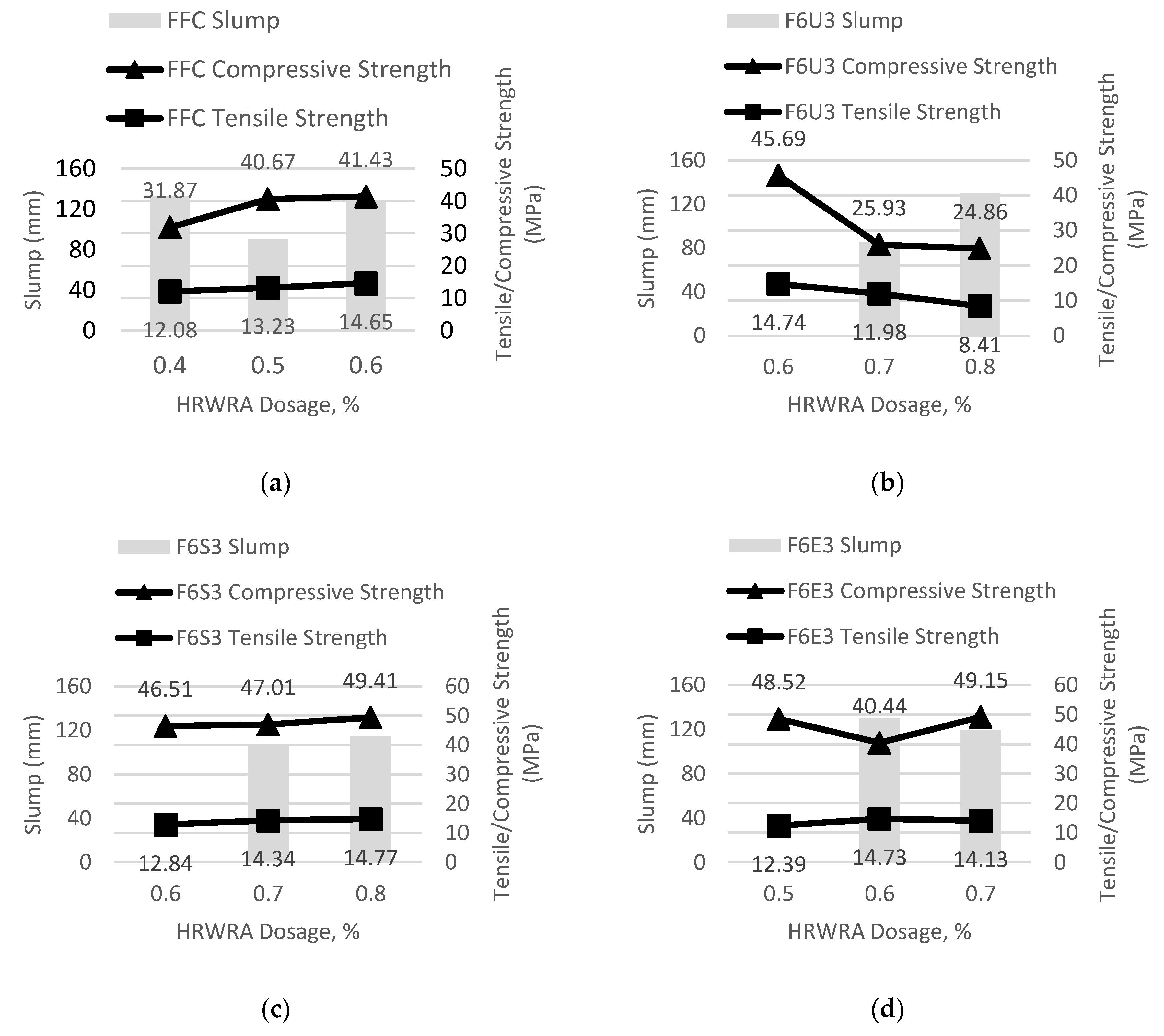
Low HRWRA application—the FFC can be classified into this tier because of the minimum 0.4% dosage to achieve a workable state and obtain a slump value. It is the only fiber combination without the use of microfibers and consists of only macro-sized blend of polypropylene and polyethylene in a fibrillated twisted form.
2.
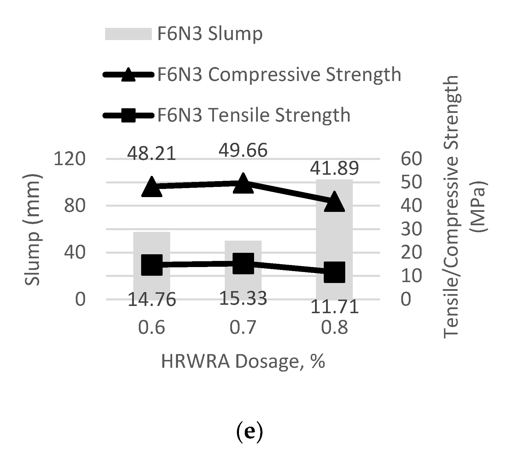
Moderate HRWRA application—this level consists of the F6E3 and F6N3 hybrids, whereby the microfibers are composed of fibrillated polypropylene and monofilament nylon. Both recorded slump values at a minimum 0.6% dosage rate and exhibit a reduction in slump when the HRWRA dosage was increased to 0.7%. The addition of microfibers results in an increase of available surface area of fibers that needs to be coated by mortar. Insufficient amount of mortar in fresh concrete that is available to bind the aggregates may cause the developed wet HyFRC to lose its workability, which explains why more HRWRA dosages were needed for these hybrids to obtain a slump value compared to the FFC. The F6N3 had a lower slump value than the F6E3 because of the nature of nylon microfibers which is hydrophilic, nylon absorbs free water in fresh concrete which in turn reduces the workability and demands a higher dosage in HRWRA.
3.
High HRWRA application—the highest tier comprises the F6U3 and F6S3 hybrids—both have polypropylene microfibers achieving a workable state at a 0.7% HRWRA dosage rate, among the highest in this parametric study. The major differences between the hybrids in this category from the moderate dosage hybrids are the microfiber specifications, which have more robust form for fiber anchorage inside concrete, a higher interfacial fiber-concrete bonding power, and a longer fiber-length. These parameters affect the workability of fresh concrete—the microfibers clump wet concrete firmly together due to the dominant fiber characteristics and result in poor workability performance.
The corresponding 28-day compressive strength of the developed HyFRC were tested and recorded as shown in Table 5. To obtain a good workability behavior is paramount in this study without losing significant loss in compressive strength. However, it was observed that the compressive strength for all the HyFRC deteriorated from the control plain concrete when a High Range Water Reducing Admixture (HRWRA) was introduced. The reduction in compressive strength was significant for the FFC at 0.4% dosage rate by as much as 40.92%, but the disparity was steadily diminishing as indicated in the 0.6% dosage rate where the strength-loss was halved to 23.19%.
Similar behavior was observed for the F6S3 hybrid, the decrease in compressive performance for this type of fiber combination was 13.77% at the starting dosage rate, but as more HRWRA were used, the cutback in performance was reduced to only 8.40%. Contrarily, the compressive strength of the F6U3 did not improve as dosage was increased—a 15.35% strength-loss was recorded at the starting dosage which further continued to a 53.91% reduction from plain concrete.
The compressive behavior of the F6E3 and F6N3 hybrid showed a comparatively irregular pattern compared to the FFC, F6S3, and F6U3. The compressive strength for the F6E3 decreased by 10.05% at the initial dosage and continued to deteriorate by 25.03% as HRWRA dosage were increased. However, the steep strength-loss was dampened when the maximum dosage of 0.7% was used, only exhibiting an 8.89% decrease from control concrete. The opposite was observed for the F6N3, the compressive strength declined by 10.62% at the starting dosage but the loss was improved to 7.93% at 0.6% dosage rate. The hybrid recorded an abrupt fall in compressive strength from plain concrete by 22.34% when the maximum dosage rate of 0.8% was applied. The comparative results in compressive strength and the trend pattern can be observed in Figure 4b.
The reduction in compressive strength can be attributed to the aggregate segregation and possible concrete bleeding during concrete mixing, which resulted in a high amount of entrapped air inside concrete [35]. Consequently, the HyFRC would have a relatively lower unit weight—affecting the compressive strength directly when high amounts of fiber volumes were used.
The tensile strength of the HyFRC was tested at 28-days and the outcome showed reasonable improvement with the addition of the HRWRA as recorded in Table 6. The FFC design indicates a marginal 7.57% decrease in tensile strength at the starting dosage of 0.4% but regained the loss in strengths as the dosage was increased. At the maximum dosage of 0.6% the tensile strength was enhanced by 12.09% relative to plain concrete. A similar pattern was observed for the F6S3 fiber combination with a 1.76% decline in tensile strength at the initial dosage of 0.6% but gradually improved the strength by as much as 13% at the maximum dosage tier of 0.8%.
It can be deduced that the FFC and F6U3 behave similarly in their response towards the inclusion of HRWRA—reducing the tensile strength when used in low dosage and improving it in high dosage. In contrast, the tensile behavior of the F6U3 hybrid is opposite to that of the FFC and F6S3 fiber-combinations. At the initial starting dosage of 0.6% the tensile strength was improved by 12.78%, however, the performance deteriorated with every increase in HRWRA dosage which eventually led to a 35.65% decline in performance at the maximum dosage limit of 0.8%.
For the case of the F6E3 and F6N3 hybrids, the tensile strength pattern is inconsistent as can be observed from Figure 4c. The F6E3 was initially weakened by 5.20% at the starting dosage but with further increase in HRWRA, the tensile strength was gradually improved by 12.70%. In addition, the F6N3 with HRWRA enhanced the tensile capability by 12.93% at 0.6% dosage rate. However, the results declined as the dosage was increased—the final dosage rate of 0.8% indicated a 10.41% decrease of tensile strength from the control specimen.
The enhancement in tensile strength was due to the presence of fibers inside cement matrix. These microfibers are useful in controlling micro-level cracks and prevent the nucleation of cracks which often propagates into single, larger macro-cracks [36]. A multi-crack hardening phenomenon increases the ultimate tensile strength of concrete as can be observed from the results of the developed HyFRC.

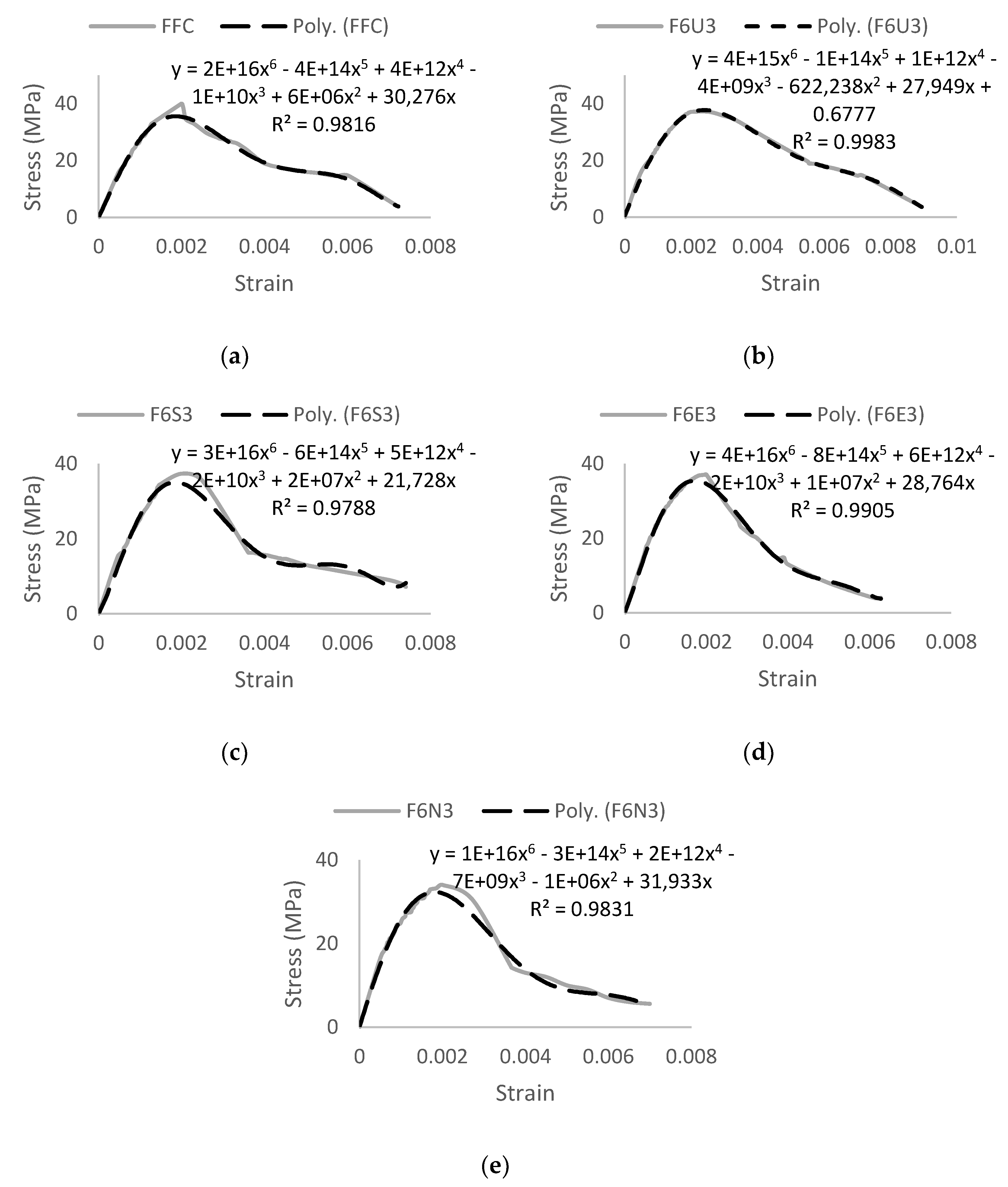
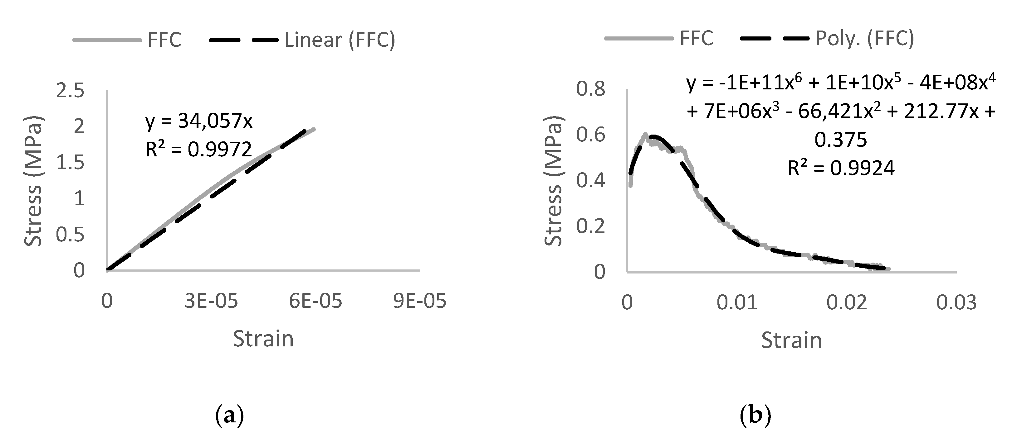
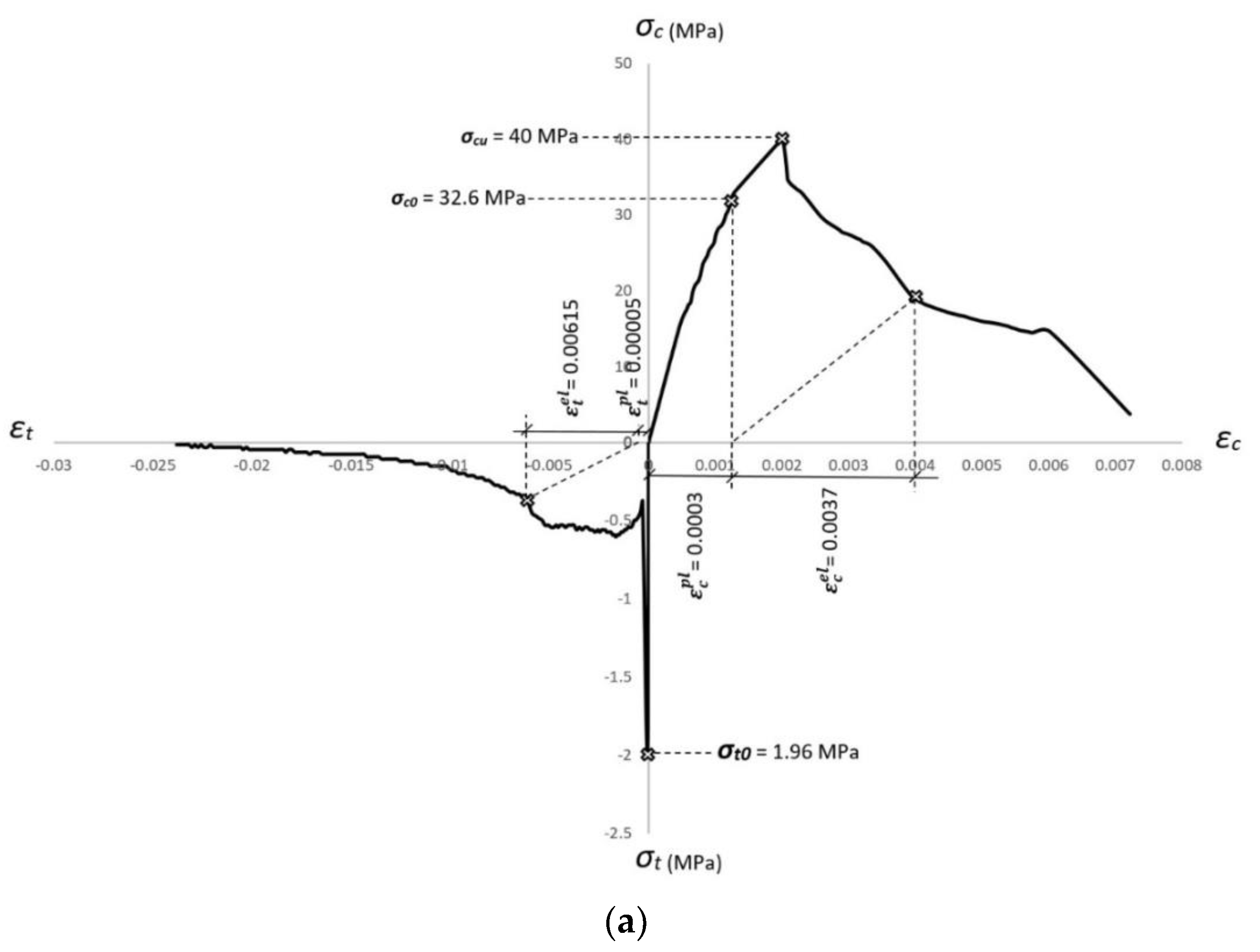
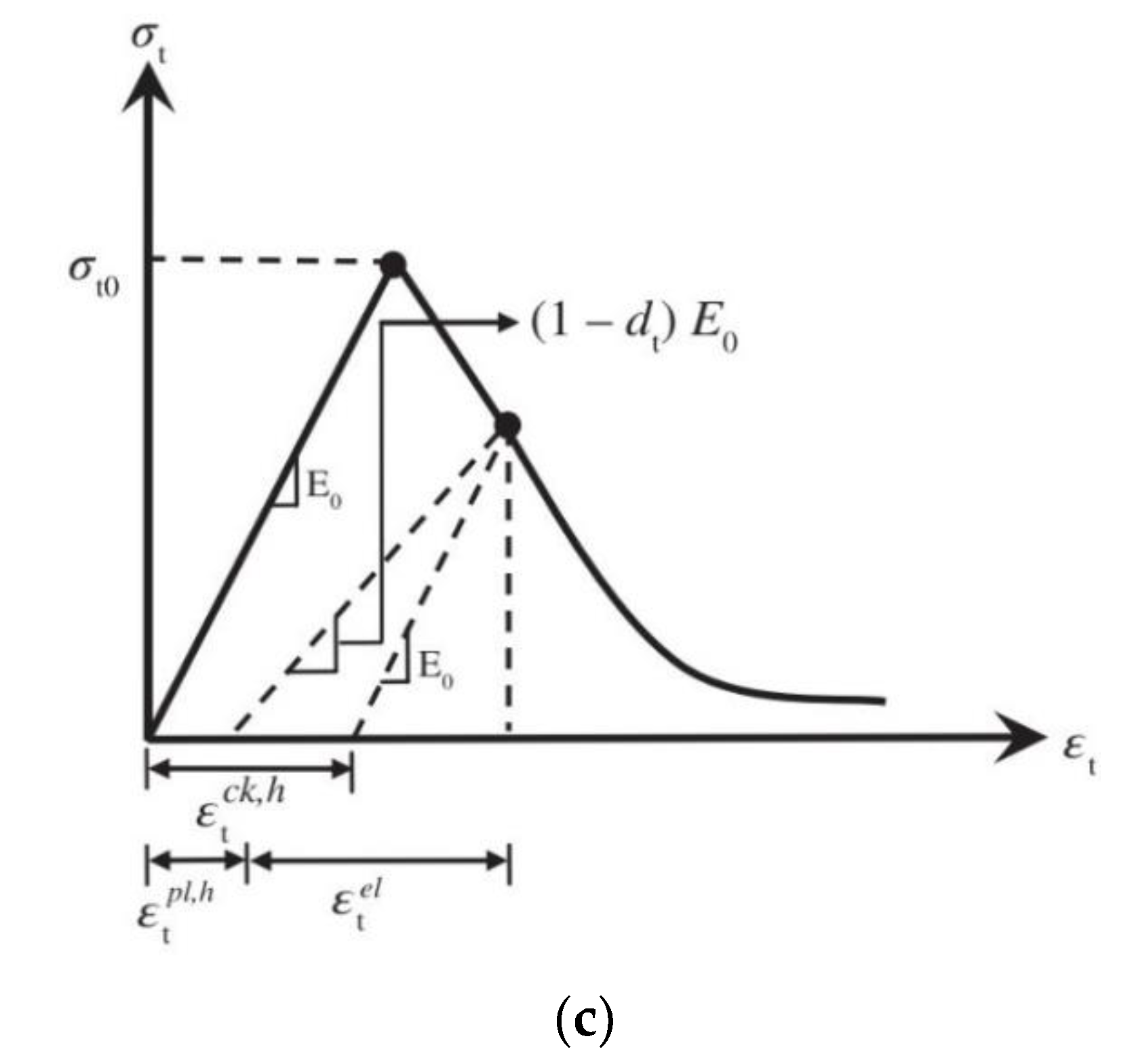
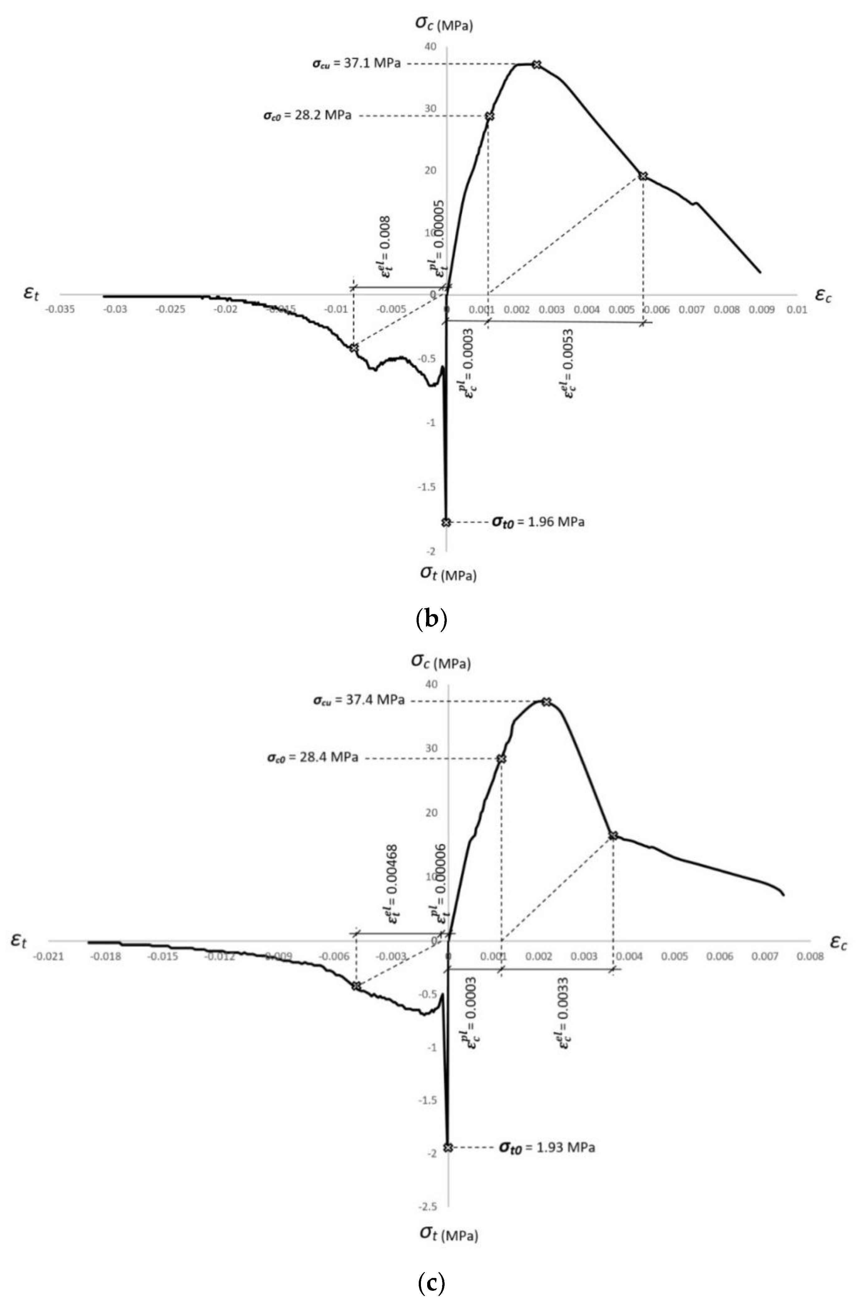
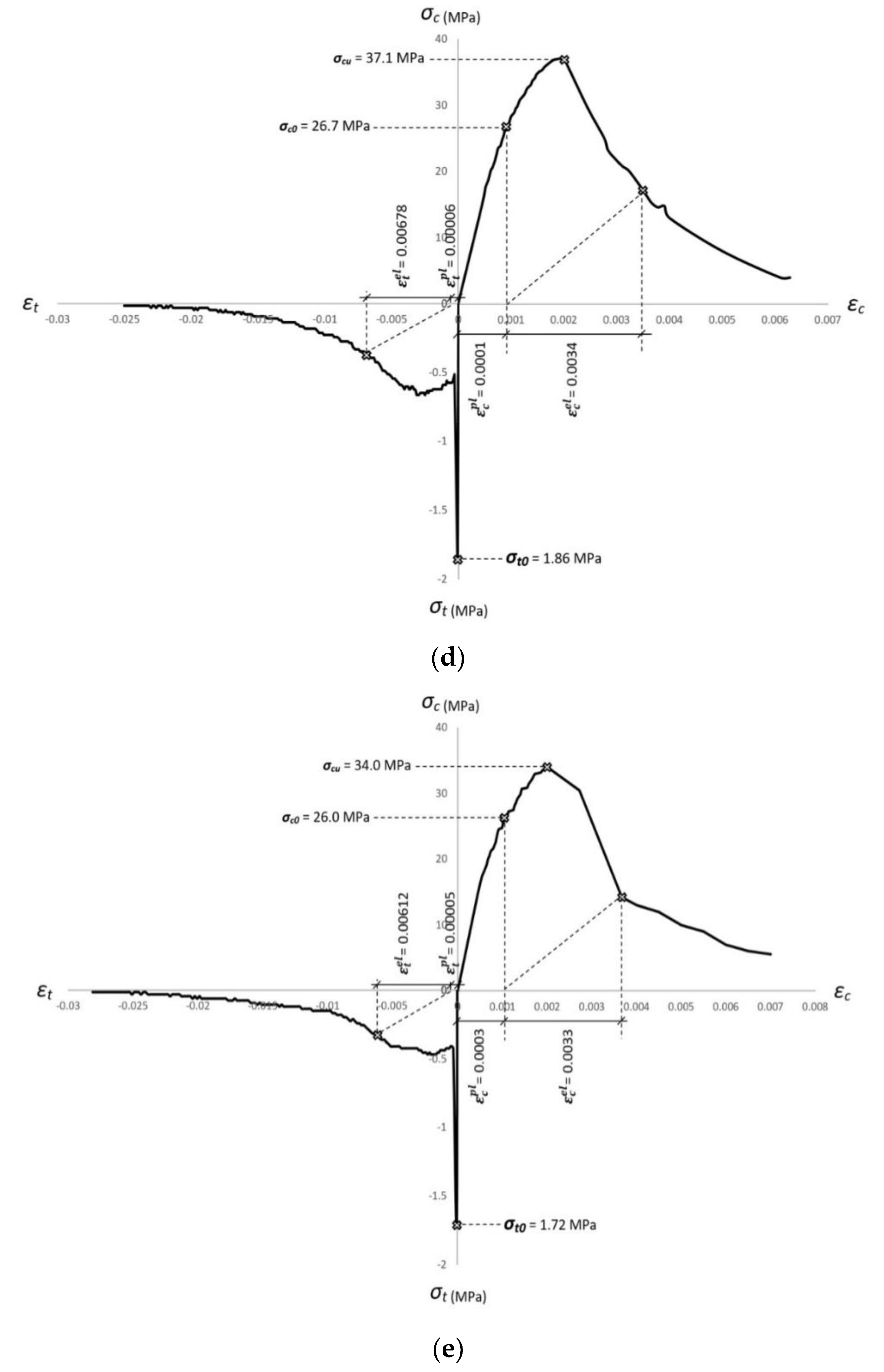
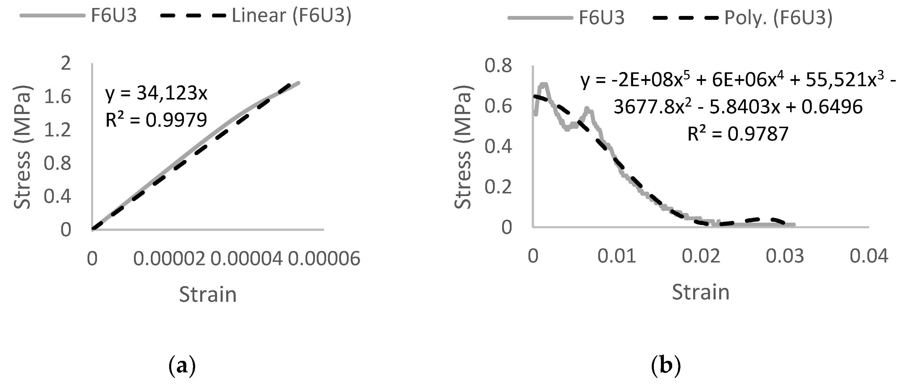
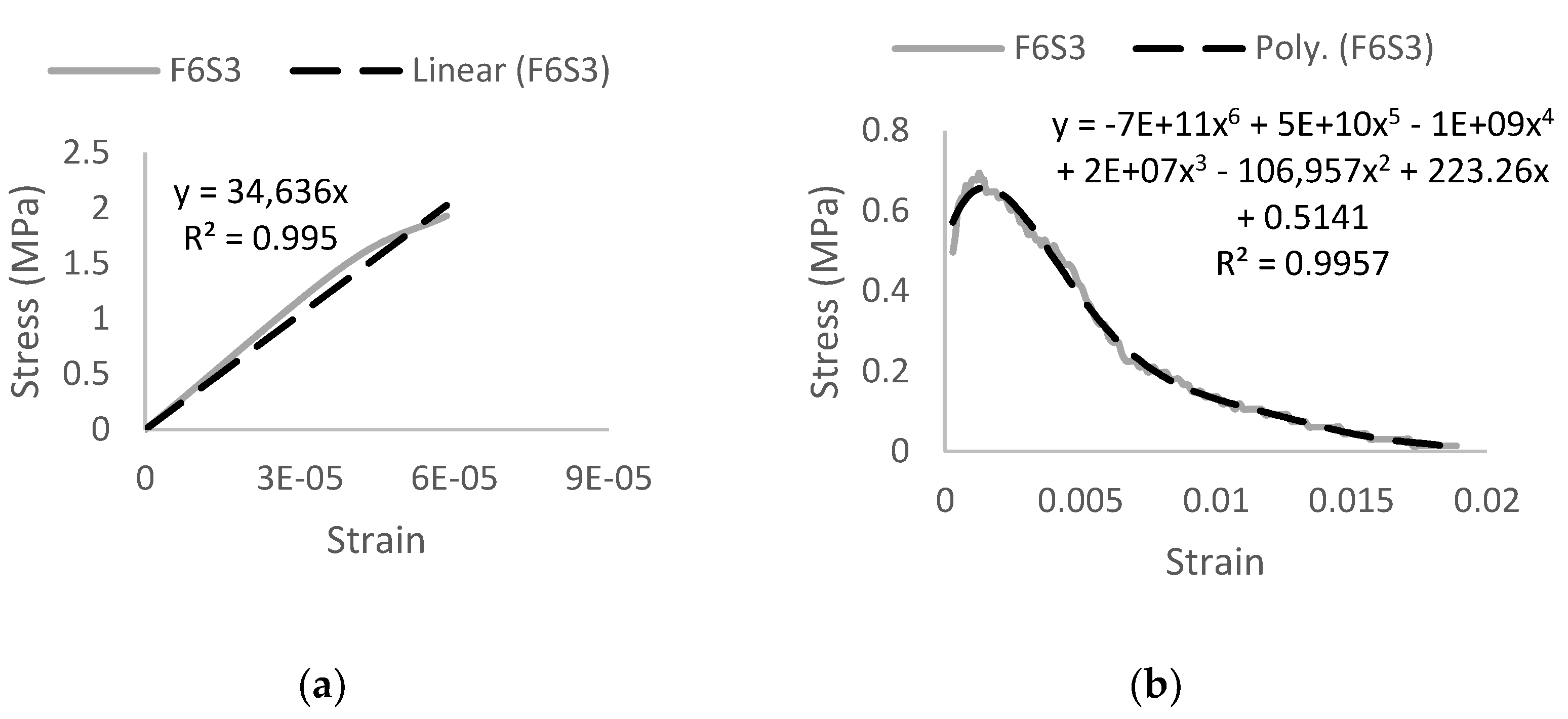
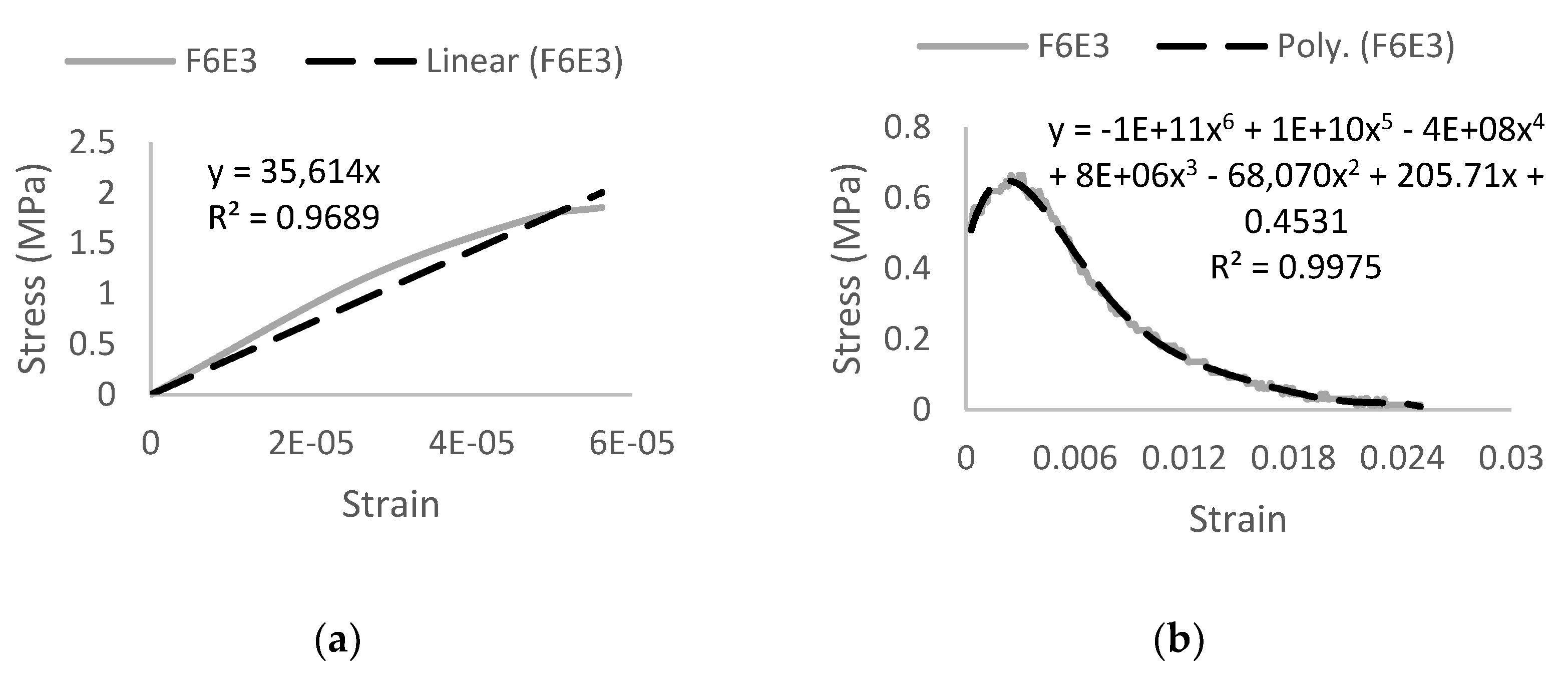
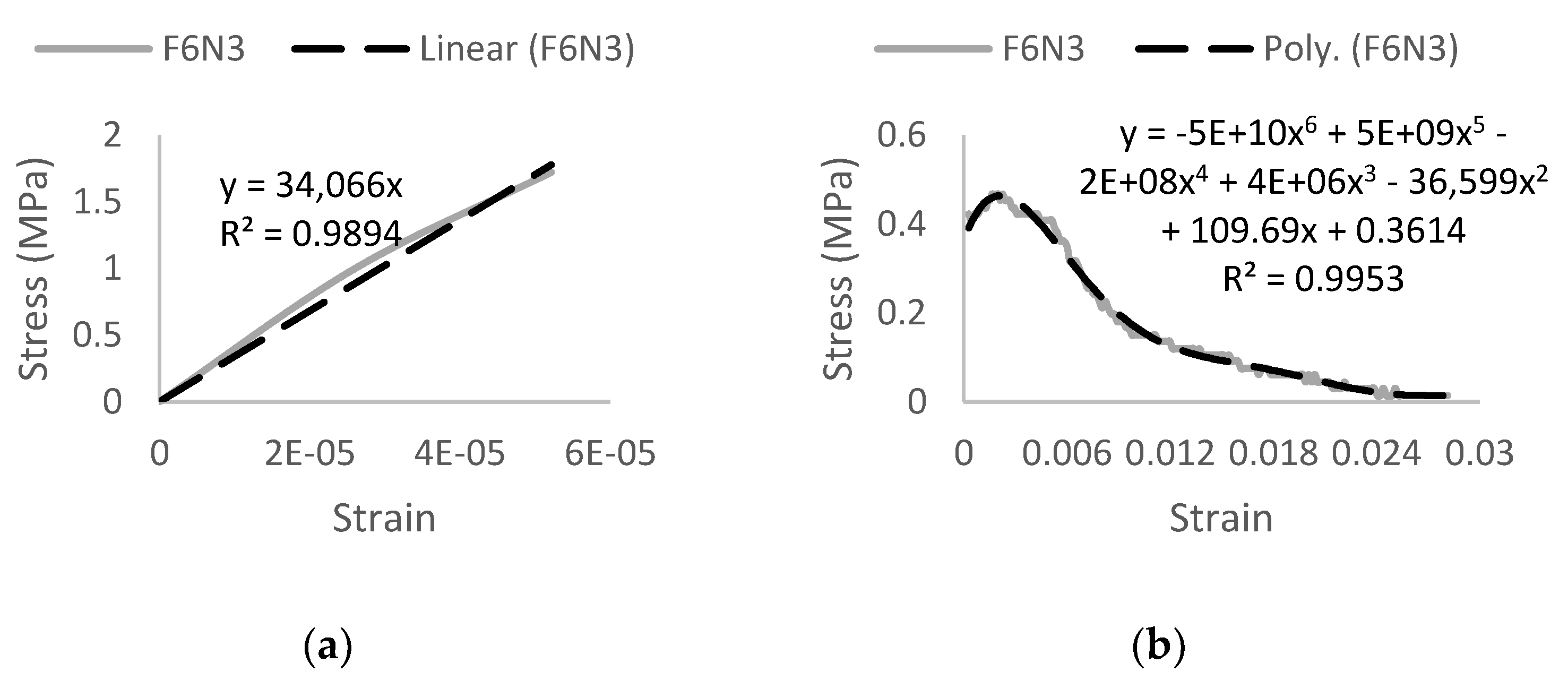
4.2. Constitutive Modeling

The FFC is a combination of the 54 and 38 mm Ferro macro synthetic fiber. The developed HyFRC produced a 40.0 MPa compressive strength at 28-days with a corresponding peak strain of 1992 µε. As indicated in Figure 5a, a sixth order polynomial curve with the equation y = 2E + 13x6 − 1E + 12x5 + 3E + 10x4 − 3E + 08x3 + 253,821x2 + 10,110x was adopted to obtain an optimal trend line from the experimental compressive stress–strain curve. The correlation factor, R2 for the polynomial trend line curve is in the range of 99.60%
The tensile strength of the HyFRC at 28-days was 1.96 MPa with a corresponding peak strain of 59 µε. In the elastic stage, a linear trend line with the equation y = 34,057x and a correlation factor, R2 of 99.23% was used to model the pre post-crack behavior of the HyFRC. In the plastic stage, a sixth order polynomial curve with the equation y = − 1E + 11x6 + 1E + 10x5 − 4E + 08x4 + 7E + 06x3 − 66,421x2 + 212.77x + 0.375 was adopted to obtain the best polynomial curve in modelling the strain-softening mode of failure. The correlation factor, R2 for this polynomial trend line curve is in the range of 99.24% as shown in Figure 6.
The compressive and tensile stress–strain curves of the developed FFC HyFRC were combined to form a constitutive model as shown in Figure 7a. In addition, the Concrete Damaged Plasticity (CDP) data collected from this model were used for verification in numerical analysis as presented in Table 7.
The Ultra-Net and Ferro fibers were combined to form the F6U4 hybrids. The Ultra-Net is a polypropylene fiber in a fibrillated twisted-bundle fashion while the Ferro is a fibrillated twisted bundle made of polypropylene and polyethylene fibers. The hybrid resulted in a 37.1 MPa compressive strength at 28-days with a corresponding peak strain of 2520 µε. From Figure 5b, a sixth order polynomial curve was selected with an optimal trend line equation of y = 4E + 15x6 − 1E + 14x5 + 1E + 12x4 − 4E + 09x3 − 622,238x2 + 27,949x + 0.6777. The correlation factor, R2 for the trend line curve is in the range of 99.83%.
The peak stress of the hybrid in tension is 1.76 MPa at 28-days with a corresponding peak strain of 53 µε. The tensile behavior is divided into elastic and plastic stages to obtain more accurate trend line curves as depicted in Figure 8. A linear trend line with the equation y = 34,123x and a fifth order polynomial curve with the equation y = − 2E + 08x5 + 6E + 06x4 + 55,521x3 − 3677.8x2 − 5.8403x + 0.6496 was adopted for the elastic and plastic stage, respectively. The correlation factor, R2 for both stages are in the range of 99.39% and 97.87%.
Figure 7b shows the combined compressive and tensile constitutive data for the F6U3 hybrids. From these data, the F6U3 CDP material properties were derived, to be used in creating FE analytical models as tabulated in Table 8.
The Super-Net is a 38 mm polypropylene fiber in a fibrillated form. It is hybridized with the Ferro macrofibers to produce the F6S3 hybrid in an attempt to improve the mechanical properties of conventional concrete. The 28-day peak compressive strength produced is 37.4 MPa with a corresponding peak strain of 2000 µε. The equation y = 3E + 16x6 − 6E + 14x5 + 5E + 12x4 − 2E + 10x3 + 2E + 07x2 + 21,728x with a correlation factor, R2 of 97.88% was obtained from the sixth order polynomial curves as shown in Figure 5c.
In tension, the HyFRC results in 1.93 MPa tensile strength at 28-days with a corresponding peak strain of 59 µε. The tensile elastic stage behavior results in a trend line equation of y = 34,636x with a correlation factor, R2 of 98.55% while the plastic stage behavior yields a y = − 7E + 11x6 + 5E + 10x5 − 1E + 09x4 + 2E + 07x3 − 106,957x2 + 223.26x + 0.5141 equation with a correlation factor, R2 in the range of 99.57%. A sixth order polynomial curve in the plastic stage curve was adopted as shown in Figure 9. The obtained compressive and tensile stress–strain curves for the F6S3 hybrid were combined to form a constitutive model as shown in Figure 7c. As tabulated in Table 9, the CDP data were derived from this constitutive curve to create F6S3 FE analytical models.
The F6E3 hybrid is a blend between the Econo-Net microfiber and the Ferro macro synthetic fibers. The Econo-Net is classified as a medium-duty fibrillated polypropylene microfiber at 38 mm length. The combination with the Ferro macro synthetic fiber yields a 28-day compressive strength of 37.1 MPa with a corresponding peak strain of 2002 µε. From Figure 5d, a sixth order polynomial curve with the equation y = 4E + 16x6 − 8E + 14x5 + 6E + 12x4 − 2E + 10x3 + 1E + 07x2 + 28,764x was adopted from the trend line of stress–strain experimental curves. The trend line curve has a correlation factor, R2 in the range of 99.05%.
The 28-days tensile strength of the F6E3 hybrid was at 1.86 MPa with a corresponding peak strain of 56 µε. The behavior in the elastic and plastic stage was divided to obtain a more accurate trend line. From Figure 10, it can be observed that a linear trend line with the equation y = 35,614x and a correlation factor, R2 of 96.89% was adopted to describe HyFRC behavior in the pre-cracking stage while the equation y = − 1E + 11x6 + 1E + 10x5 − 4E + 08x4 + 8E + 06x3 − 68,070x2 + 205.71x + 0.4531 with a correlation factor, R2 of 99.75% was adopted to describe the post-cracking behavior, from a sixth order polynomial curve’s trend line.
As with the previous HyFRC designs, the stress–strain combined data obtained from uniaxial compressive and tensile tests are shown in Figure 7d.The data derived from the stress–strain curve determined the CDP material properties, which was essential in describing the behavior of the HyFRC in the proposed FE analytical models. The properties are tabulated below in Table 10.
The final design is the F6N3 combination—it is a mixture of the Nylo-Mono microfiber with the Ferro macro synthetic fibers. This microfiber is also the only nylon fiber used in this research; level 1 FORTA fibers are classified as a light-duty monofilament fiber that has a length of 19 mm. The combination with the Ferro produced a HyFRC with a compressive strength of 34.0 MPa at 28-days with a corresponding peak strain of 2008 µε. As indicated in Figure 5e, the trend line equation obtained from the sixth order polynomial curve is y = 1E + 16x6 − 3E + 14x5 + 2E + 12x4 − 7E + 09x3 − 1E + 06x2 + 31,933x and has a correlation factor, R2 of 98.31%.
The F6N3 design results in a concrete hybrid that has a 1.72 MPa tensile strength at 28-days with a corresponding peak strain of 52 µε. The elastic behavior of the HyFRC yielded a linear trend line curve of y = 34,066x with a correlation factor, R2 of 98.94%. Additionally, a trend line curve of equation y = − 5E + 10x6 + 5E + 09x5 − 2E + 08x4 + 4E + 06x3 − 36,599x2 + 109.69x + 0.3614 was adopted from a sixth order polynomial curve to describe the best behavior in stress–strain of the HyFRC. The correlation factor, R2 for the curve was is the range of 99.53% as shown in Figure 11.
The compressive and tensile stress–strain data of the F6N3 HyFRC design mix were combined to form a constitutive model as illustrated in Figure 7e. The data were then derived to obtain CDP material properties to be used in creating analytical FE models. The CDP material properties are tabulated in Table 11.

5. Assessment of Results

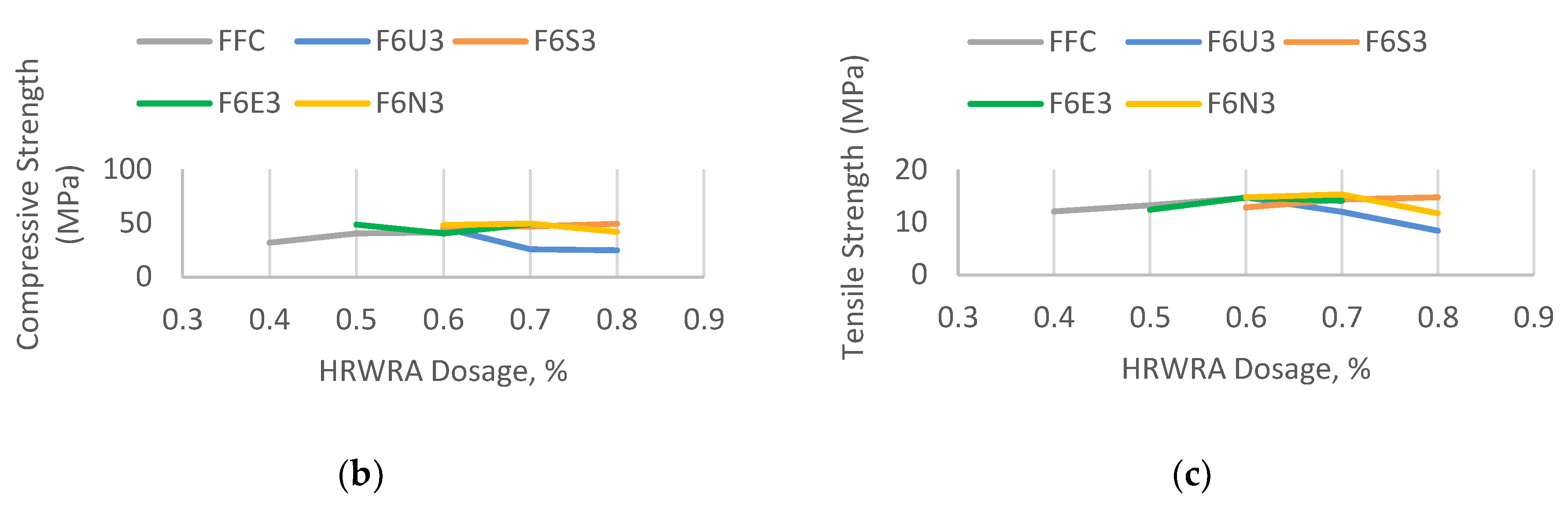
5.1. Evaluation of HRWRA Effect

Each of the hybrids displayed different behavior in workability and also in its corresponding strength in both compression and tension. The main objective is to obtain ample workability behavior measured through the slump value without significant loss in compressive strength, while also procuring the best enhancement in tensile strength. These three criteria are superimposed against one another in a column and line graph to identify the effective applicational dosage.
The FFC mix-design exhibited an incline trend in both compressive and tensile strength with an increase in HRWRA dosage. As can be observed in Figure 12a, the best dosage to be applied for this HyFRC is 0.6%—the percentage difference with the highest slump in the 0.4% tier is only at a minimal 3.45%, providing the best workability with the highest corresponding compressive and tensile behavior.
The F6U3 hybrids showed a decline in strength with the increase in HRWRA dosage as shown in Figure 12b. The most significant deterioration was from the 0.6–0.7% dosage rate by 43.25% for the compressive strength and 18.72% for the tensile strength which continued to decrease at the 0.8% dosage tier. In order to procure adequate workability without substantial loss in strength, the 0.7% HRWRA dosage was chosen.
In Figure 12c, the F6S3 fiber combination displayed an increased workability behavior with every increment in HRWRA dosage. The compressive and tensile strength is directly proportional to the increase in slump, herewith making 0.8% dosage the most suitable HRWRA prescription for this HyFRC mix design.
The irregular pattern in compressive strength and slump workability for the F6E3 hybrids are shown in Figure 12d. The best dosage rate to be applied into this HyFRC mix-design is the 0.7% dosage, which exhibited the best compressive strength along with a reasonable loss in tensile strength and slump. The decrease in tensile strength and slump from the 0.6% tier was only at a minimal 4.07% and 8.46% compared to the 17.72% decline in compressive strength from the 0.7% dosage rate to the 0.6% tier.
The F6N3 fiber-combination exhibited a decreasing compressive and tensile strength with incremental dosage of HRWRA. The most significant decline was from 0.7% to 0.8% dosage rate by 15.65% for compressive strength and 23.61% for tensile strength as indicated in Figure 12e. Therefore, the 0.7% dosage was considered for this mix design due to the best retention-loss of compressive strength while achieving the highest tensile strength. Although the slump is less than the 0.6% tier, the difference was minimal.

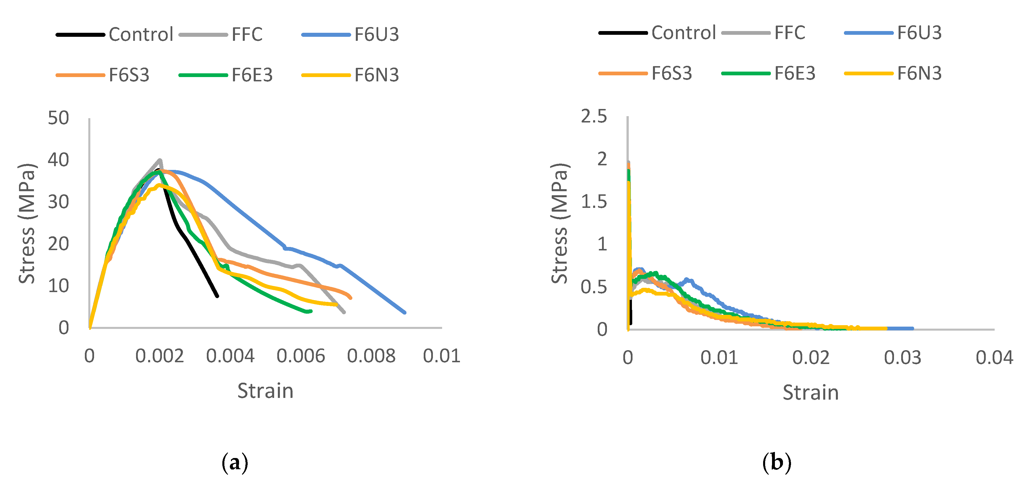
5.2. Uniaxial Behavior Comparative Analysis

The stress–strain behavior of all the developed HyFRC was compiled in Table 12 for comparison. It is indicated in Figure 13a that at 2000 µε, the FFC showed the best compressive behavior in the elastic stage with a 40 MPa peak compressive strength and a corresponding strain of 1992 µε; increasing the performance of plain concrete by 6.67%. The F6U3, F6S3, and F6E3 performed almost similarly to the controlled plain concrete with a slight decrease in performance by 1.07%, 0.27%, and 1.07%, respectively. However, the F6N3 combination weakens conventional concrete in compression by 9.33% with a corresponding strain of 2008 µε. The FFC has no microfibers and only consists of macro-sized fibers. This proved beneficial because the addition of microfibers, as shown in the other designs have made concrete more brittle, due to the fiber-bridging of micro-level cracks [37]. This concrete hardening scenario in the elastic stage prevented a pull-out mode of failure for the Ferro fiber—breaking it during the rapid crack propagation without having sufficient opportunity to bridge the widening macro-sized gaps progressively.
However, for the range greater than 2000 µε, the F6U3 demonstrated the best behavior in the post-cracking region. Its maximum deflection reached to 8944 µε, a 147% increase from plain concrete and a 26.51% increase from FFC. Although the micro-macro fiber relationship results in fiber-breakage in the elastic stage, the combination of the FORTA fibers proved efficient at a much higher deformation. Even though the Ultra-Net is a micro-class fiber, it has been shown in previous residual strength tests that it supplements the Ferro in fiber-bridging cracks even in the macro-level. This dampens the rate of crack propagation in concrete thus allowing sufficient opportunity for the Ferro fiber to achieve a gradual pull-out mode of failure. Henceforth, the added residual strength improved the compressive post-crack behavior—significantly better than just using macrofiber-only FFC design. The F6S3, F6E3, and F6N3 delivered a relatively poor performance in those regions but only at a minimal difference of 0.41%, 0.50%, and 0.8% from the FFC. Nevertheless, all of the developed HyFRC have improved the plastic behavior of plain concrete in compression substantially.
The compressive damage in the HyFRC cylinders is shown in Figure 14. It was observed that the control specimens absorbed the highest damage followed by the FFC. The control cylinder specimens were completely fractured and although the FFC-design was stronger in the elastic stage, it consumed a lot of damage in the post-cracking region, as can be seen with the numerous large crack-sizes on the specimens. The F6U3, F6S3, F6E3, and F6N3 specimens exhibited minimal differences in compressive damage with each other, but all displayed less cracks than the FFC and control specimens. This is because of the more effective crack-bridging effect of the macro-micro fiber combinations as shown in Figure 15.
In the case of tensile behavior, Figure 13b illustrates the different post-cracking performance for the developed HyFRC. It can be observed that plain concrete is brittle in nature, instantly failing to 0.08 MPa with a corresponding strain of 302 µε after achieving peak stress. However, the addition of fibers inside the cementitious composite changed the mode of failure from brittle to strain-softening with a surge of strain hardening in-between. At the range below 60 µε, the FFC displayed the best tensile behavior in the elastic stage with a 1.96 MPa strength and a corresponding strain of 59 µε. The advantage of lacking in microfibers for the FFC proved beneficial in tension as it was in compression—increasing the tensile strength of plain concrete by 37.06%. The subsequent best is the F6S3 with a 34.97% increase in performance followed by the F6E3, F6U3, and F6N3 with a 30.07%, 23.08%, and 20.28% increase, respectively.
However, the performance of the FFC deteriorates when the deformation is greater than 60 µε in the plastic region. The F6U3 produced the best post-cracking tensile behavior with a peak strain hardening at 0.71 MPa with a corresponding strain of 1552 µε. This increased the control specimen plastic strength by an additional 0.63 MPa. The other developed HyFRC also provided additional residual strength to plain concrete by 0.52, 0.61, 0.58, and 0.39 MPa for the FFC, F6S3, F6E3, and F6N3 mix-design accordingly. In addition, the F6U3, F6S3, and F6E3 achieved a higher strain-hardening tensile strength than the FFC macrofiber-only design with a difference of 16.79%, 13.95%, and 9.52% in post-cracking performance.
The F6N3 is weaker than the FFC because the Nylo-Mono microfiber in the hybrid has the shortest fiber length in this study as well as having the least bonding power and anchorage capacity compared to the Ultra-Net, Super-Net, and Econo-Net microfibers. Although the Nylo-Mono has the highest tensile strength, nylons depend more on the fiber/cement interface rather than the elongation limit when in pull-out failure [38]. The monofilament form made the fiber inept to strongly anchor itself inside cementitious composites while the low-duty bonding power between the interfacial fiber surface did not provide adequate friction during pull-out to contribute in tensile strength. Furthermore, the 19 mm length was too short to fiber-bridge the widening crack gaps in the post-cracking region; and without the dampening of crack propagation in the elastic stage, the rapid crack localization would occur rapidly and transforms the mode of failure of the Ferro macrofiber from fiber pull-out to fiber-breakage, thus weakening the HyFRC in tension.

6. Concluding Remarks

In this study, the Hybrid Fiber Reinforced Concrete (HyFRC) materials were developed by hybridizing synthetic fibers from FORTA Corporation with the additional use of ADVA Cast 512 polymer-based High Range Water-Reducing Admixture (HRWRA) from GCP Applied Technologies during the concrete mixing process.
  • The addition of HRWRA in the hybrid-mixes was studied, observed, and assessed to determine the best dosage requirement for improved workability behavior, compressive and tensile strengths. The optimal HRWRA dosage for the Ferro-Ferro hybrids are 0.6%, 0.7% for the Ferro-Ultra, Ferro-Econo, Ferro-Nylo hybrids, and 0.8% for the Ferro-Super hybrids.
  • The developed HyFRC improved the compressive and tensile mechanical properties of cementitious composites reasonably. The Ferro-Ferro hybrids exhibited the best performance in the elastic stage in both compression and tension while in the plastics stage, the Ferro-Super hybrids displayed the best compressive strain-hardening while the Ferro-Super hybrids excelled the most in the tensile post-cracking stage.
  • Constitutive models were developed for all five HyFRC materials for future works. Predictive works for structural application can be conducted from the constitutive laws while FE analyses can be accomplished by modeling RC structures using the Concrete Damaged Plasticity (CDP) data in the materials properties in this study.

Author Contributions

Conceptualization, S.M.I.S.Z. and F.H.; Data creation, S.M.I.S.Z. and F.H.; Formal analysis, S.M.I.S.Z.; Methodology, S.M.I.S.Z. and F.H.; Project administration, F.H.; Resources, F.H.; Software, S.M.I.S.Z. and F.H.; Supervision, F.H.; Writing—original draft, S.M.I.S.Z.; Writing—review and editing, F.H., F.N.A.A.A. and M.S.J. All authors have read and agreed to the published version of the manuscript.

Funding

This research was funded by Universiti Putra Malaysia (UPM) under the Putra Grant Research Project, No. 9531200.

Acknowledgments

The authors would like to thank Innofloor Sdn. Bhd. as the Malaysian FORTA Corporation supplier for providing the fibers to conduct this research. Their support is gratefully acknowledged.

Conflicts of Interest

The authors declare no conflict of interest.

References

  1. ACI Committee 544. State-of-the-Art Report on Fiber Reinforced Concrete. J. Proc. 2002, 70, 729–744. [Google Scholar]
  2. Walton, P.L.; Majumdar, A.J. Cement Based Composites with Mixtures of Different Types of Fibres. Composites 1975, 6, 209–216. [Google Scholar] [CrossRef]
  3. Banthia, N.; Sheng, J. Micro-reinforced Cementitious Materials. MRS Proc. 1991, 211, 25–32. [Google Scholar] [CrossRef]
  4. Mobasher, B.; Li, C. Mechanical Properties of Hybrid Cement Based Composites. ACI Mater. J. 1996, 93, 284–292. [Google Scholar]
  5. Ramanalingam, N.; Paramasivam, P.; Mansur, M.A.; Maalej, M. Flexural Behaviour of Hybrid Fiber-Reinforced Cement Composites Containing High-Volume Fly Ash. Symp. Pap. 2001, 199, 147–162. [Google Scholar]
  6. Sun, W.; Chen, H.; Luo, X.; Qian, H. The effect of hybrid fibers and expansive agent on the shrinkage and permeability of high performance concrete. Cem. Concr. Res. 2001, 31, 595–601. [Google Scholar] [CrossRef]
  7. Banthia, N.; Nandakumar, N. Crack Growth Resistance of Hybrid Fiber Reinforced Cement Composites. Cem. Concr. Compos. 2003, 25, 3–9. [Google Scholar] [CrossRef]
  8. Banthia, N.; Soleimani, S.M. Flexural response of hybrid fiber-reinforced cementitious composites. ACI Mater. J. 2005, 102, 382–389. [Google Scholar]
  9. Banthia, N.; Gupta, R. Hybrid Fiber Reinforced Concrete: Fiber Synergy in High Strength Matrices. RILEM Mater. Struct. 2004, 37, 707–716. [Google Scholar] [CrossRef]
  10. Yu, J.; Yao, J.; Lin, X.; Li, H.; Lam, J.Y.K.; Leung, C.K.Y.; Sham, I.M.L.; Shih, K. Tensile performance of sustainable Strain-Hardening Cementitious Composites with hybrid PVA and recycled PET fibers. Cem. Concr. Res. 2018, 107, 110–123. [Google Scholar] [CrossRef]
  11. Roesler, J.R.; Altoubat, S.A.; Lange, D.A.; Rieder, K.A.; Ulreich, G.R. Effect of synthetic fibers on structural behavior of concrete slabs-on-ground. ACI Mater. J. 2006, 103, 3–10. [Google Scholar]
  12. Greenough, T.; Nehdi, M. Shear Behaviour of Self-Consolidating Fibre-Reinfored Concrete Slender Beams. ACI Mater. J. 2008, 105, 468–477. [Google Scholar]
  13. Altoubat, S.; Yazdanbakhsh, A.; Rieder, K.A. Shear behavior of macro-synthetic fiber-reinforced concrete beams without stirrups. ACI Mater. J. 2009, 106, 381–389. [Google Scholar]
  14. Kawashima, K.; Zafra, R.G.; Sasaki, T.; Kajiwara, K.; Nakayama, M. Effect of Polypropylene Fiber Reinforced Cement Composite and Steel Fiber Reinforced Concrete for Enhancing the Seismic Performance of Bridge Columns. J. Earthq. Eng. 2011, 15, 1194–1211. [Google Scholar] [CrossRef]
  15. Yu, K.; Wang, Y.; Yu, J.; Xu, S. A strain-hardening cementitious composites with the tensile capacity up to 8%. Constr. Build. Mater. 2017, 137, 410–419. [Google Scholar] [CrossRef]
  16. Kawashima, K.; Zafra, R.G.; Sasaki, T.; Kajiwara, K.; Nakayama, M.; Unjoh, S.; Sakai, J.; Kosa, K.; Takahashi, Y.; Yabe, M. Seismic Performance of a Full-Size Polypropylene Fiber-Reinforced Cement Composite Bridge Column Based on E-Defense Shake Table Experiments. J. Earthq. Eng. 2012, 16, 463–495. [Google Scholar] [CrossRef]
  17. Spadea, S.; Farina, I.; Berardi, V.P.; Dentale, F.; Fraternali, F. Energy dissipation capacity of concretes reinforced with recycled PET fibers. Ing. Sismica 2014, 31, 61–70. [Google Scholar]
  18. Ganesan, N.; Indira, P.V.; Sabeena, M.V. Bond stress slip response of bars embedded in hybrid fibre reinforced high performance concrete. Constr. Build. Mater. 2014, 50, 108–115. [Google Scholar] [CrossRef]
  19. Pakravan, H.R.; Ozbakkaloglu, T. Synthetic fibers for cementitious composites: A critical and in-depth review of recent advances. Constr. Build. Mater. 2019, 207, 491–518. [Google Scholar] [CrossRef]
  20. Curosu, I.; Liebscher, M.; Mechtcherine, V.; Bellmann, C.; Michel, S. Tensile behavior of high-strength strain-hardening cement-based composites (HS-SHCC) made with high-performance polyethylene, aramid and PBO fibers. Cem. Concr. Res. 2017, 98, 71–81. [Google Scholar] [CrossRef]
  21. Yin, S.; Tuladhar, R.; Collister, T.; Combe, M.; Sivakugan, N. Mechanical Properties and Post-crack Behaviours of Recycled PP Fibre Reinforced Concrete. In Proceedings of the Concrete 2015, 27th Biennial National Conference of the Concrete Institute of Australia in Conjunction with the 69th RILEM Week “Construction Innovations, Research into Practice, Melbourne, Australia, 30 August–2 September 2015. [Google Scholar]
  22. Shen, L.; Worrell, E.; Patel, M.K. Open-loop recycling: A LCA case study of PET bottle-to-fibre recycling. Resour. Conserv. Recycl. 2010, 55, 34–52. [Google Scholar] [CrossRef]
  23. Kheni, D.; Scott, R.H.; Deb, S.K.; Dutta, A. Ductility enhancement in beam-column connections using hybrid fiber-reinforced concrete. ACI Struct. J. 2015, 112, 167–178. [Google Scholar] [CrossRef]
  24. ASTM C494/C494M-17. Standard Specification for Chemical Admixtures for Concrete; ASTM International: West Conshohocken, PA, USA, 2017. [Google Scholar]
  25. ACI Committee 212. Guide for the Use of High-Range Water-Reducing Admixtures (Superplasticizers) in Concrete; ACI: Farmington Hills, MI, USA, 2017; p. 13. [Google Scholar]
  26. ASTM C143/C143M-15a. Standard Test Method for Slump of Hydraulic-Cement Concrete; ASTM International: West Conshohocken, PA, USA, 2015. [Google Scholar]
  27. BS EN 1992-2:2005. Concrete. Complementary British Standard to BS EN 206. Specification for Constituent Materials and Concrete; British Standards Institution: London, UK, 2019. [Google Scholar]
  28. ASTM C496/C496M-11. Standard Test Method for Splitting Tensile Strength of Cylindrical Concrete Specimens; ASTM International: West Conshohocken, PA, USA, 2011. [Google Scholar]
  29. ASTMC469/C469M-14. Standard Test Method for Static Modulus of Elasticity and Poisson’s Ratio of Concrete; ASTM International: West Conshohocken, PA, USA, 2014. [Google Scholar]
  30. Hassan, A.M.T.; Jones, S.W.; Mahmud, G.H. Experimental test methods to determine the uniaxial tensile and compressive behaviour of Ultra High Performance Fibre Reinforced Concrete (UHPFRC). Constr. Build. Mater. 2012, 37, 874–882. [Google Scholar] [CrossRef]
  31. Kent, D.C.; Park, R. Flexural Members with Confined Concrete. J. Struct. Eng. Div. 1971, 97, 1969–1990. [Google Scholar]
  32. Park, R. Reinforced Concrete Structures; John Wiley & Sons: New York, NY, USA, 1975. [Google Scholar]
  33. Ananiev, S.; Ozbolt, J. A plastic-damage model for concrete. Int. J. Solids Struct. 1989, 25, 299–326. [Google Scholar]
  34. JSCE Concrete Committee. Recommendations for Design and Construction of High Performance Fiber Reinforced Cement Composites with Multiple Fine Cracks (HPFRCC); Japan Society of Civil Engineers, Concrete Committee: Tokyo, Japan, 2008. [Google Scholar]
  35. Ramakrishnan, V.; Wu, G.Y.; Hosalli, G. Flexural Fatigue Strength, Endurance Limit, and Impact Strength of Fiber Reinforced Concretes. In Proceedings of the International Symposium on Recent Developments in Concrete Fiber Composites; Transportation Research Board: Washington, DC, USA, 1989; pp. 17–24. [Google Scholar]
  36. Lawler, J.; Zampini, D.; Shah, S. Microfiber and Macrofiber Hybrid Fiber-Reinforced Concrete. J. Mater. Civ. Eng. 2005, 17, 595–604. [Google Scholar] [CrossRef]
  37. Betterman, L.R.; Ouyang, C.; Shah, S.P. Fiber-matrix interaction in microfiber-reinforced mortar. Adv. Cem. Based Mater. 1995, 2, 53–61. [Google Scholar] [CrossRef]
  38. Pakravan, H.R.; Jamshidi, M.; Latifi, M. Polymeric fibers pull out behavior and microstructure as cementitious composites reinforcement.pdf. J. Text. Inst. 2013, 104, 1056–1065. [Google Scholar] [CrossRef]
Figure 1. The uniaxial compression test: (a) conceptual, (b) actual.
Crystals 10 00885 g001
Figure 2. The (a) model for confined and unconfined concrete [31] as well as the (b) compressive and (c) tensile behavior of concrete in uniaxial conditions [33].
Crystals 10 00885 g002aCrystals 10 00885 g002b
Figure 3. The uniaxial tensile test: (a) conceptual, (b) actual.
Crystals 10 00885 g003
Figure 4. The (a) slump comparison and the (b) compressive and (c) tensile strength at 28-days.
Crystals 10 00885 g004aCrystals 10 00885 g004b
Figure 5. Uniaxial compression stress–strain curve: (a) FFC, (b) F6U3, (c) F6S3, (d) F6E3, (e) F6N3.
Crystals 10 00885 g005
Figure 6. FFC uniaxial tension stress–strain curve: (a) elastic stage and (b) plastic stage.
Crystals 10 00885 g006
Figure 7. Constitutive models for the developed HyFRC in compression and tension: (a) FFC, (b) F6U3, (c) F6S3, (d) F6E3, (e) F6N3.
Crystals 10 00885 g007aCrystals 10 00885 g007bCrystals 10 00885 g007c
Figure 8. F6U3 uniaxial tension stress–strain curve: (a) elastic stage and (b) plastic stage.
Crystals 10 00885 g008
Figure 9. F6S3 uniaxial tension stress–strain curve: (a) elastic stage and (b) plastic stage.
Crystals 10 00885 g009
Figure 10. F6E3 uniaxial tension stress–strain curve: (a) elastic stage and (b) plastic stage.
Crystals 10 00885 g010
Figure 11. F6N3 uniaxial tension stress–strain curve: (a) elastic stage and (b) plastic stage.
Crystals 10 00885 g011
Figure 12. HyFRC dosage requirement (bar chart: slump, line graph: compressive/tensile strength): (a) FFC, (b) F6U3, (c) F6S3, (d) F6E3, (e) F6N3.
Crystals 10 00885 g012aCrystals 10 00885 g012b
Figure 13. HyFRC tensile stress–strain curve comparison: (a) uniaxial compression, (b) uniaxial tension.
Crystals 10 00885 g013
Figure 14. HyFRC damage in compression: (a) control, (b) FFC, (c) F6U3, (d) F6S3, (e) F6E3, (f) F6N3.
Crystals 10 00885 g014aCrystals 10 00885 g014b
Figure 15. The fiber-bridging effect as shown in tension: (a) Uniaxial testing under tension for dog-bone specimens (b) Fiber-bridging effect during uniaxial tensile test.
Crystals 10 00885 g015
Table 1. Specifications for FORTA fibers. (U: Ultra-Net; S: Super-Net, E: Econo-Net; N: Nylo-Mono; FF: Ferro).
TypeLength (mm)FormBonding PowerClassMaterialTensile Strength (MPa)
U54Fibrillated Twisted bundleExtra heavy-dutyMicroPolypropylene and additives570–660
S38FibrillatedHeavy-duty570–660
E38FibrillatedMedium-duty570–660
N19MonofilamentLight-dutyVirgin nylon966
FF138Fibrillated Twisted bundleHeavy-dutyMacroPolyethylene, polypropylene, and additives1100
FF254Heavy-duty570–660
Table 2. Selected Hybrid Fiber Reinforced Concrete (HyFRC) for constitutive modeling. (C: Control; U: Ultra-Net; S: Super-Net; E: Econo-Net; F: Ferro).
SpecimensDesignationType of Fibers (Vol. of Fraction, %)Total Vol. Fraction, (%)
MacroFibersMicroFibers
FF1FF2UNSNENNM
1Control-------
2FFC0.60.6----1.20
3F6U30.60.60.30---1.50
4F6S30.60.6-0.30--1.50
5F6E30.60.6--0.30-1.50
6F6N30.60.6---0.301.50
Table 3. Admixture tests on developed HyFRC (X: Tested).
SpecimenDesignationAdmixture Dosage (%)
0.200.300.400.500.600.700.800.901.00
1C (Plain)
2FFCX XXX
3F6U3 XXX X
4F6S3 XXX
5F6E3 XXX
6F6N3 XXX
Table 4. Average slump for developed HyFRC (σ = standard deviation).
HRWRA
(%)
Average Slump (mm)
FFCF6U3F6S3F6E3F6N3C
0.20----90 *
(σ: 5.48)
0.3-----
0.4132.5
(σ: 8.22)
0
(σ: 0)
---
0.590
(σ: 6.23)
--0
(σ: 0)
-
0.6128
(σ: 1.10)
0
(σ: 0)
0
(σ: 0)
130
(σ: 10.45)
57.50
(σ: 10.98)
0.7-85
(σ: 10.85)
106.5
(σ: 10.07)
119
(σ: 6.57)
50
(σ: 10.84)
0.8-130
(σ: 10.91)
115
(σ: 4.38)
-102.5
(σ: 8.22)
0.9-----
1.0-110
(σ: 10.93)
---
* HRWRAs were not added to plain concrete.
Table 5. Average 28-day compressive strength (σ = standard deviation).
HRWRA
(%)
Average Compressive Strength (MPa)
FFCF6U3F6S3F6E3F6N3C
0.243.97
(σ: 2.18)
----53.94 *
(σ: 0.23)
0.3-----
0.431.87
(σ: 1.42)
----
0.540.67
(σ: 1.44)
--48.52
(σ: 0.57)
-
0.641.43
(σ: 3.37)
45.69
(σ: 2.38)
46.51
(σ: 2.21)
40.44
(σ: 0.18)
48.21
(σ: 1.44)
0.7-25.93
(σ: 5.63)
47.01
(σ: 1.20)
49.15
(σ: 3.07)
49.66
(σ: 0.90)
0.8-24.86
(σ: 0.38)
49.41
(σ: 1.99)
-41.89
(σ: 2.00)
0.9-----
1.0-26.47
(σ: 0.99)
---
* Compressive strength without HRWRAs.
Table 6. Average 28-days tensile strength (σ = standard deviation).
HRWRA
(%)
Average Tensile Strength (MPa)
FFCF6U3F6S3F6E3F6N3C
0.215.29
(σ: 0.69)
----13.07 *
(σ: 0.27)
0.3-----
0.412.08
(σ: 0.56)
----
0.513.23
(σ: 2.26)
--12.39
(σ: 0.31)
-
0.614.65
(σ: 0.20)
14.74
(σ: 1.33)
12.84
(σ: 0.44)
14.73
(σ: 1.18)
14.76
(σ: 1.39)
0.7-11.98
(σ: 0.55)
14.34
(σ: 0.84)
14.13
(σ: 2.70)
15.33
(σ: 0.60)
0.8-8.41
(σ: 0.69)
14.77
(σ: 0.19)
-11.71
(σ: 0.62)
0.9-----
1.0-10.66
(σ: 0.04)
---
* Tensile strength without HRWRAs.
Table 7. Material properties of FFC HyFRC.
Material ParametersFFCPlasticity Parameters
Concrete ElasticityDilation Angle31
E (GPa)33Eccentricity0.1
fb0/fc01.16
N0.2K0.67
Viscosity Parameter0
Compressive BehaviorCompression Damage
Yield Stress (MPa)Inelastic StrainDamage Parameter CInelastic Strain
15.2000
20.70.000069894700.0000698947
26.30.000179100.0001791
30.70.00026744100.000267441
32.60.00027587700.000275877
33.10.00028938800.000289388
40.00.00078107400.000781074
38.00.0008995450.050.000899545
35.40.0010065980.110.001006598
34.70.0010384640.130.001038464
33.80.0011552710.160.001155271
30.00.0016648560.250.001664856
25.30.0026538930.370.002653893
20.10.0032718530.50.003271853
15.20.0049900530.620.004990053
3.70.0071104120.910.007110412
Tensile BehaviorTension Damage
Yield Stress (MPa)Cracking StrainDamage Parameter TCracking Strain
1.9600.000
0.380.0002890320.810.000289032
0.600.0016343740.690.001634374
0.590.0018038150.700.001803815
0.570.001888830.710.00188883
0.540.0049039460.720.004903946
0.360.0061958470.820.006195847
0.120.012541420.940.01254142
0.030.0219622840.980.021962284
Table 8. Material properties of F6U3 HyFRC.
Material ParametersF6U3Plasticity Parameters
Concrete ElasticityDilation Angle31
E (GPa)33Eccentricity0.1
fb0/fc01.16
N0.2K0.67
Viscosity Parameter0
Compressive BehaviorCompression Damage
Yield Stress (MPa)Inelastic StrainDamage Parameter CInelastic Strain
15.2000
22.50.00018243500.000182435
27.80.00031071900.000310719
33.70.00057820200.000578202
34.80.00064047200.000640472
35.70.00070891500.000708915
36.90.00083292100.000832921
37.10.00139529700.001395297
35.90.0018522030.030.001852203
34.20.0023113730.080.002311373
28.20.0033606570.240.003360657
18.00.0054571890.520.005457189
16.90.0058818040.540.005881804
14.90.0064855560.600.006485556
3.70.0088332240.900.008833224
Tensile BehaviorTension Damage
Yield Stress (MPa)Cracking StrainDamage Parameter TCracking Strain
1.7600.000
0.560.0003474010.680.000347401
0.590.0004256750.670.000425675
0.710.0015308550.600.001530855
0.500.0040558130.720.004055813
0.590.0064607150.670.006460715
0.420.0083190450.760.008319045
0.170.0130075090.910.013007509
0.030.0213989140.980.021398914
Table 9. Material properties of F6S3 HyFRC.
Material ParametersF6S3Plasticity Parameters
Concrete ElasticityDilation Angle31
E (GPa)33Eccentricity0.1
fb0/fc01.16
N0.2K0.67
Viscosity Parameter0
Compressive BehaviorCompression Damage
Yield Stress (MPa)Inelastic StrainDamage Parameter CInelastic Strain
15.2000
21.00.00013949300.000139493
28.90.00031767300.000317673
30.70.00034749000.000347490
32.20.00040150200.000401502
33.60.00041181300.000411813
34.40.00042758500.000427585
37.40.00086800000.000868000
35.30.0014421950.050.001442195
16.30.0031120600.560.003112060
16.00.0033467120.570.003346712
15.80.0033722390.580.003372239
15.30.0037849180.590.003784918
14.60.0040806770.610.004080677
13.00.0071891070.810.007189107
Tensile BehaviorTension Damage
Yield Stress (MPa)Cracking StrainDamage Parameter TCracking Strain
1.93000
0.500.0002856330.740.000285633
0.540.0003812860.720.000381286
0.600.0004570340.690.000457034
0.690.0012496560.640.001249656
0.540.0032621860.720.003262186
0.380.0052168520.800.005216852
0.170.0089674490.910.008967449
0.030.0171292740.980.017129274
Table 10. Material properties of F6E3 HyFRC.
Material ParametersF6E3Plasticity Parameters
Concrete ElasticityDilation Angle31
E (GPa)33Eccentricity0.1
fb0/fc01.16
N0.2K0.67
Viscosity Parameter0
Compressive BehaviorCompression Damage
Yield Stress (MPa)Inelastic StrainDamage Parameter CInelastic Strain
15.2000
20.60.00002691000.000026910
30.80.00023649700.000236497
35.00.00047228100.000472281
36.90.00075235500.000752355
37.00.00082754300.000827543
37.10.00087897700.000878977
29.70.0015464110.200.001546411
25.00.0020087890.320.002008789
23.30.0021293710.370.002129371
21.80.0023221700.410.002322170
20.10.0026263710.460.002626371
17.40.0029576420.530.002957642
15.10.0032337650.590.003233765
14.60.0033599270.610.003359927
Tensile BehaviorTension Damage
Yield Stress (MPa)Cracking StrainDamage Parameter TCracking Strain
1.86000
0.510.0002847280.720.000284728
0.560.0003834810.700.000383481
0.660.0031137820.640.003113782
0.630.0031917080.660.003191708
0.620.0032691290.670.003269129
0.360.0068266570.810.006826657
0.180.0107052290.900.010705229
0.030.0187485740.980.018748574
Table 11. Material properties of F6N3 HyFRC.
Material ParametersF6N3Plasticity Parameters
Concrete ElasticityDilation Angle31
E (GPa)33Eccentricity0.1
fb0/fc01.16
N0.2K0.67
Viscosity Parameter0
Compressive BehaviorCompression Damage
Yield Stress (MPa)Inelastic StrainDamage Parameter CInelastic Strain
15.2000
18.80.00005189200.000051892
20.20.00006484800.000064848
26.00.00025558600.000255586
30.80.00061636500.000616365
31.50.00063081100.000630811
32.50.00069944200.000699442
33.00.00071726600.000717266
33.20.00084839500.000848395
33.50.00087382600.000873826
34.00.00097671600.000976716
30.50.0018013820.100.001801382
14.80.0031854800.560.003185480
14.20.0032374920.580.003237492
5.60.0068301730.840.006830173
Tensile BehaviorTension Damage
Yield Stress (MPa)Cracking StrainDamage Parameter TCracking Strain
1.72000
0.420.0002888050.750.000288805
0.410.0004972260.760.000497226
0.470.0022530590.730.002253059
0.410.0051148260.760.005114826
0.320.0061576040.820.006157604
0.200.0087404240.890.008740424
0.110.0150768010.940.015076801
0.030.0238566740.980.023856674
Table 12. Comparison between the developed HyFRC.
Mix DesignCFFCF6U3F6S3F6E3F6N3
Compressive strength, MPa37.540.037.137.437.134.0
Corresponding strain, µε200019922520200020022008
Tensile strength, MPa1.431.961.761.931.861.72
Corresponding strain, µε435953595652
Max. strain deflection in compression, µε362772248944740662796999
Peak tensile strain-hardening, MPa0.080.600.710.690.660.47
Corresponding strain, µε30216531552127131342267

