Abstract
In this work, chemical vapor infiltration (CVI) was combined with reactive melt infiltration (RMI) using Ti–6Al–4V titanium alloy powder to prepare Cf/C–TiC composites. The microstructure and composition of Cf/C–TiC composites were characterized by scanning electron microscopy (SEM) and X-ray diffraction (XRD). The flexural properties of the composites were also analyzed. The results indicated that the Ti–6Al–4V titanium alloy infiltrated the Cf/C preform and reacted with the pyrolytic carbon (PyC) to form a TiC–VC and Al4C3 matrix, and no residual Ti, Al, or V was detected. Moreover, Al4C3 was concentrated and independently distributed, whereas Ti and V reacted with C to form a TiC–VC solid solution. The porosity was 6.75%, and the bulk density of Cf/C–TiC was 1.96 g/cm3. The flexural strength, flexural modulus, and failure strains were 256 ± 18 MPa, 89 ± 9 GPa, and 0.93 ± 0.13%, respectively. The work of fracture of the Cf/C–TiC composite was about 6.8 ± 0.38 KJ/m2. Due to the propagation and deflection of cracks, as well as debonding and fiber pullout, the Cf/C–TiC composite showed ductile fracture behavior.
1. Introduction
Continuous fiber-reinforced ceramic matrix composites (CMCs) have been widely used in aerospace and nuclear industries due to their high-temperature oxidation resistance and good toughness. Reinforcing fibers mainly include carbon fibers and SiC fibers, whereas ceramic matrix materials include SiC, ZrC, and TiC. Carbon fiber-reinforced CMC preparation methods include chemical vapor deposition (CVD) [1], polymer impregnation and pyrolysis (PIP) [2,3], and reactive melt infiltration (RMI) [4]. However, CVD and PIP methods increase the cost of fabrication processes due to preparation times of hundreds of hours. In contrast, the RMI method has been widely studied due to its short preparation time, low cost, and near-net-shape production [5]. Moreover, an unreacted pyrolytic carbon (PyC) layer exists between the ceramic matrix and carbon fibers, which acts as a good interface between the ceramic phase and fibers when the Cf/C–TiC is under load. Due to the load transmission and crack deflection at the interface, composites formed by RMI tend to have higher mechanical properties [6,7,8].
TiC ceramics are widely used due to their high hardness, high melting points, and relatively high thermal and electrical conductivities [9,10], and they also exhibit good oxidation and corrosion resistance [11]. However, as a typical ceramic material, the brittleness of TiC greatly limits its application; therefore, a variety of studies have examined methods to improve the toughness of TiC ceramics. The introduction of carbon fibers in TiC ceramics has been shown to greatly improve their mechanical and thermal shock properties. Short carbon fiber-reinforced TiC composites, 2D Cf/C–TiC, and 3D Cf/C–TiC composites have been prepared using hot pressing (HP), chemical vapor infiltration (CVI), and RMI, respectively [12,13,14,15]. The results showed that the mechanical properties of TiC were greatly improved due to the introduction of carbon fibers.
Many studies have reported the preparation of carbon fiber-reinforced CMCs using RMI [16,17,18,19,20], but there are few reports detailing the preparation of Cf/C–TiC using this method. In this work, Cf/C–TiC composites with good mechanical properties were prepared by combining CVI with RMI.
2. Experimental Procedure
Ti–6Al–4V titanium alloy powder (Shanghai, China) was used. Carbon fiber needled felts (Tianniao, Jiangsu, China), fabricated by the three-dimensional needle-punching method, were used as preforms.
Ti–6Al–4V titanium alloy is an (α + β)-type titanium alloy with good comprehensive mechanical properties. It is a typical as-cast titanium alloy with good fluidity in liquid state, which allowed it to penetrate into the porous preform very well.
The carbon fiber preform was prepared by alternately laminating a non-woven fabric and a net tire, and then piercing the fibers in the net tire vertically into the non-woven fabric using a needle-punching method. The schematic illustration of the preform is shown in Figure 1.
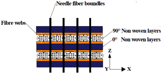
Figure 1.
The schematic of the architecture of the 3D needle-puncture fiber felt.
The preparation process of Cf/C–TiC composites was as follows: first, propylene (C3H6) was used as a carbon source, and N2 was used as a dilution gas to deposit a certain amount of PyC in the carbon fiber preform, thus preparing a Cf/C preform. The Cf/C preform was then embedded in a Ti–6Al–4V titanium alloy powder within a graphite crucible when the density of the preform reached about 1.30 g/cm3. Finally, the graphite crucible was placed in a vacuum furnace and heated to 1800 °C for two hours. At 1800 °C, the titanium alloy melted, infiltrated the C/C preform, and reacted with PyC to form a ceramic matrix, and the Cf/C–TiC composite was obtained.
The method of mass divided by volume was used to measure the apparent density of the composites. The open porosity of the composites was measured by the Archimedes drainage method. Equations (1) and (2) were used to calculated density (ρ) and open porosity (P) of the composites:
where m1 is the mass of the samples after drying, m3 is the mass after the samples were saturated with water, and m2 is the mass of the samples in water. The flexural strength and elastic modulus of the composites were measured at ambient temperature by three-point bending tests [21] on an Instron 5565-5KN system (Boston, MA, USA), with a span of 50 mm and crosshead speed of 0.5 mm/min. The size of each sample was 50 × 4 × 3 mm, and three samples were tested. The formula for bending strength (σ3b) is as follows:
where P is the maximum applied load (N) during the test, S is the span (mm), B is the width of the sample (mm), and H is the height of the sample (mm). The fracture work can also be obtained from the characteristic area (Ac) under the load–displacement curve, divided by the cross-section of the specimen. In order to effectively determine the fracture work, Ac was defined as covering between the initial point and the point at which there is a 10% drop of the maximum load in the load–displacement curve. Fracture work was calculated using the following formula [22]:
where H and B are the thickness and broadness of the sample, respectively.
In this work, a JSM-6360LV SEM (JEOL, Japan) equipped with an energy spectrometer was used to observe the microstructure, fracture morphology, and composition of composites. X-ray diffraction (XRD, Max 2500PC, Rigaku, Japan) was used to determine the phases of composites. The XRD radiation was Ni-filtered Cu Kα. The scanning rate was 5°/min and the 2θ scanning range was 10° to 80°.
3. Results and Discussion
3.1. Density and Microstructure
The porosity and density of the Cf/C preform before infiltration were 22.83% and 1.30 g/cm3, respectively, whereas the porosity and density of the composites after RMI were 6.75% and 1.96 g/cm3, respectively. This shows that the Ti–6Al–4V titanium alloy powder infiltrated the Cf/C preform, which reduced the porosity and increased the density of the material. Figure 2a,b shows that ceramic phases were generated in the preform.
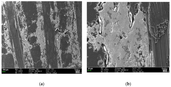
Figure 2.
Typical SEM micrographs of the Cf/ C-TiC composite (a) 21×. (b) 2000×.
The EDS maps in Figure 3a,b and the XRD maps in Figure 4 show that the ceramic phases in the matrix included Al3C4 and TiC–VC. TiC and VC have the same lattice type, both of them are face-centered cubic structures, and their lattice constants are also close. Therefore, TiC and VC easily form composite carbides during solidification [23] and Al3C4 phases. The Al3C4 phase was mainly distributed around the TiC–VC. In Figure 4, the broad carbon peak refers to the carbon fibers and residual PyC. The TiC–VC and Al3C4 phases resulted from the in situ reactions of titanium, vanadium, and aluminum with PyC.
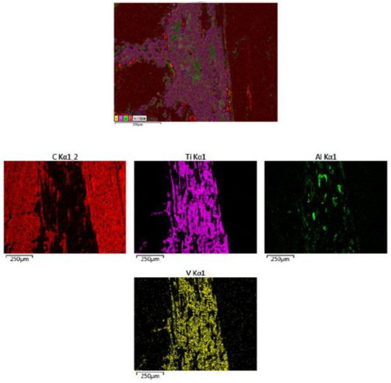
Figure 3.
The EDS maps image of the Cf/C-TiC composite.
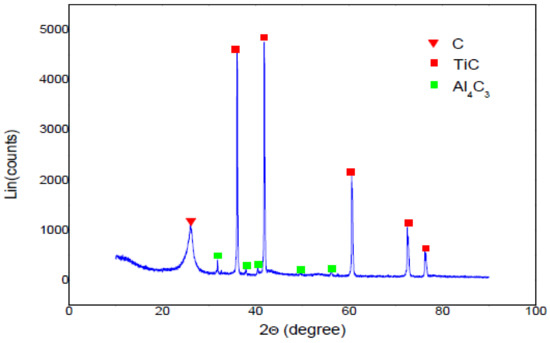
Figure 4.
XRD patterns of the Cf/C-TiC composite.
Due to the low fracture toughness and relatively low melting point of Si [24], residual Si severely reduced the performance of composites during the Cf/C–SiC composite preparation by RMI. In the Cf/C–TiC composites, no residual Ti, Al, or V was detected. Al4C3 was concentrated and independently distributed, whereas TiC and VC fused together to form a TiC–VC solid solution. This happened because the Al (the lowest melting point material) melted first, and reacted with the PyC to form an Al4C3 ceramic, then Ti and V melted and reacted with PyC to form a TiC–VC ceramic. Because of the low content of Al and V, Al reacted with C to form Al4C3, whereas V, Ti, and C reacted to form a TiC–VC solid solution, so there was no detectable residual Al or V. When the PyC reacted with liquid Ti, the thickness of the TiC layer was about 160 μm, whereas the pore radius of the Cf/C preform before infiltration was less than 130 μm. Therefore, when the titanium alloy melted, infiltrated the Cf/C preform, and reacted with PyC, the residual liquid Ti was extruded out of pores by the formed solid titanium. Thus, there was no residual Al, V, or Ti in the composite matrix.
3.2. Mechanical Properties
The flexural strength and flexural modulus of the prepared Cf/C–TiC composites, tested at room temperature, were about 256 ± 18 MPa and 89 ± 9 GPa, respectively. The failure strain of Cf/C–TiC was 0.93% ± 0.13%. The work of fracture of the Cf/C–TiC composite was about 6.8 ± 0.38 KJ/m2. The bending strength–displacement curve is shown in Figure 5, which shows that as the load increases, the displacement first increases linearly, then increases nonlinearly to a maximum load value, and finally slowly decreases until the material breaks. The load–displacement curve of the Cf/C preform decreases rapidly as the load reaches a maximum, demonstrating a high degree of toughness of Cf/C–TiC composites. In the Cf/C body, two kinds of pores exist in the preform. One is bigger, distributed among the carbon fiber bundles, and the other is smaller, distributed inside the carbon fiber bundles. The material section in Figure 6 shows that after reaction infiltration, the two kinds of pores inside the Cf/C body were filled with the ceramic phase, which greatly improved the bending strength of the composite. During the load application, the cracks were effectively transferred from the PyC to the ceramic matrix and then carbon fibers, which effectively consumed the load energy, resulting in an improvement in the mechanical properties [25,26].
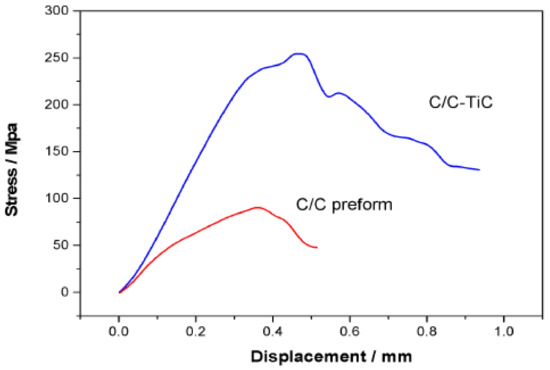
Figure 5.
Typical stress-displacement curves for the Cf/C-TiC and the Cf/C preform.
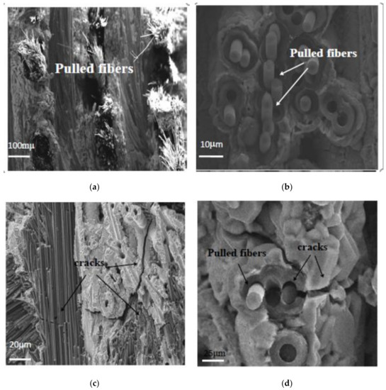
Figure 6.
SEM photographs of the fracture surfaces of the Cf/C-TiC composite. (a,b) Carbon fibers pulling-out, and (c,d) crack propagation and deflection in Cf/C-TiC composite.
As can be seen from Figure 6, during material breakage, a large number of fibers were pulled out. This shows that the fibers were effectively subjected to the load, and absorbed the load energy during loading, which gave the material considerable toughness. The EDS elemental maps of composite cross-sections are shown in Figure 7. At the periphery of the fibers, there is first a layer of PyC, then a layer of Al4C3, and the outermost layer is a TiC–VC matrix. As shown in Figure 6, when Cf/C–TiC composites are under load, cracks were first generated in PyC, and then passed through the ceramic matrix, and finally onto the carbon fibers. When the cracks propagated to the ceramic matrix, they first passed through the interface between PyC and Al4C3, and then through the interface between Al4C3 and TiC–VC. It was more difficult for the crack propagation to proceed, and significant energy was consumed, and the material exhibited a high degree of toughness.
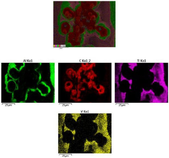
Figure 7.
The EDS maps image of the section of Cf/C-TiC composite.
4. Conclusions
A Cf/C–TiC composite was successfully prepared using a reactive infiltration method with a Ti–6Al–4V titanium alloy. The open porosity, bulk density, flexural strength, and flexural modulus of the prepared composite were 6.75%, 1.96 g/cm3, 256 ± 18 MPa, and 89 ± 9 GPa, respectively. The work of fracture of the Cf/C–TiC composite tested at room temperature was about 6.8 ± 0.38 KJ/m2. XRD analysis showed that the main components of the material were carbon, Al4C3, and TiC–VC, and no residual Al, V, or Ti was found. EDS elemental maps showed that the Al4C3 was mainly concentrated along the periphery of TiC ceramics, while V reacted with C to form a TiC–VC solid solution. When a load was applied to the material, cracks were first generated in the PyC, then passed through the interface of PyC and Al4C3, then through the interface of Al4C3 and TiC–VC. After that, cracks were deflected in the TiC–VC solid solution, and finally propagated to the carbon fibers, pulling the fibers out. During this process, most of the energy was consumed, which improved the mechanical properties of the composite.
Author Contributions
Conceptualization, Y.N.; methodology, Y.N.; software, Y.N.; validation, Y.N.; formal analysis, Y.N.; investigation, Y.N.; resources, Y.N.; data curation, Y.N.; writing—original draft preparation, Y.N.; writing—review and editing, Y.N.; visualization, Y.N.; supervision, Y.N.; project administration, R.L.; funding acquisition, R.L. All authors have read and agreed to the published version of the manuscript.
Funding
This work was supported by the National Natural Science Foundation of China (No. 21071011).
Acknowledgments
First and foremost, I would like to show my deepest gratitude to my tutor, Ruiying Luo, a respectable, responsible and resourceful scholar, who has provided me with valuable guidance in every stage of the writing of this manuscript. Without his enlightening instruction, impressive kindness and patience, I could not have completed my thesis. His keen and vigorous academic observation enlightens me not only in this thesis but also in my future study.
Conflicts of Interest
The authors declare no conflict of interest. The funders had no role in the design of the study; in the collection, analyses, or interpretation of data; in the writing of the manuscript, or in the decision to publish the results.
References
- Naslain, R.; Pailler, R.; Bourrat, X.; Bertarnd, S.; Lamouroux, L. Synthesis of highly tailored ceramic matrix composites by pressure-pulsed CVI. Solid State Ionics 2001, 541, 141–144. [Google Scholar] [CrossRef]
- Sato, K.; Tezuka, A.; Funayama, O.; Isoda, T.; Terada, Y.; Kato, S.; Iwata, M. Fabrication and pressure testing of a gas-turbine component manufactured by a pre ceramic–polymer-impregnation method. Compos. Sci. Technol. 1999, 59, 853–859. [Google Scholar] [CrossRef]
- Kohyama, A.; Kotani, M.; Katoh, Y.; Nakayasu, T.; Sato, M.; Yamamura, T.; Okamura, K. High performance SiC/SiC composites by improved PIP processing with new precursor polymers. J. Nucl. Mater. 2000, 283, 565–569. [Google Scholar] [CrossRef]
- Jiang, S.Z.; Xiong, X.; Chen, Z.K.; Xiao, P.; Huang, B.Y. Influence factors of C/C–SiC dual matrix composites prepared by reactive melt infiltration. Mater. Des. 2009, 30, 3738–3742. [Google Scholar]
- Einset, E.O. Analysis of reactive melt infiltration in the processing of ceramics and ceramic composites. Chem. Eng. Sci. 1998, 53, 1027–1039. [Google Scholar] [CrossRef]
- Storms, E.K. The Refractory Carbides; Academic Press: New York, NY, USA, 1967. [Google Scholar]
- Lengauer, W. Handbook of Ceramic Hard Materials; Riedel, R., Ed.; WileyVCH: New York, NY, USA, 2003; pp. 202–203, 234–235, 238. [Google Scholar]
- Vallauri, D.; Adrian, I.C.A.; Chrysanthou, A. TiC–TiB2 composites: A review of phase relationships, processing and properties. J. Eur. Ceram. Soc. 2008, 28, 1697–1713. [Google Scholar] [CrossRef]
- Song, G.M.; Wu, Y.; Li, Q. Elevated temperature strength and thermal shock behavior of hot-pressed carbon fiber reinforced TiC composites. J. Eur. Ceram. Soc. 2002, 22, 559–566. [Google Scholar] [CrossRef]
- Song, G.M.; Li, Q.; Wen, G.W.; Zhou, Y. Enhanced Microwave Absorption of SiO2-Coated Fe0.65Co0.35 Flakes at a Wide Frequency Band (1–18 GHz). Mater. Sci. Eng. A 2002, 326, 240–246. [Google Scholar] [CrossRef]
- Rossignol, J.Y.; Quenisset, J.M.; Naslain, R. Mechanical behaviour in compression loading of 2D-composite materials made of carbon fabrics and a ceramic matrix. Composites 1987, 18, 135–144. [Google Scholar] [CrossRef]
- Tong, Y.G. A low cost fabrication route for continuous carbon fiber reinforced TiC based ceramic matrix composites. J. Mater. Sci. Eng. A 2012, 556, 980–983. [Google Scholar] [CrossRef]
- Trantina, G.G.; Mehan, R.L. High-temperature time-dependent strength of an Si/SiC composite. J. Am. Ceram. Soc. 1977, 3, 177–178. [Google Scholar] [CrossRef]
- Zou, L.H.; Wali, N.; Yang, J.M. Microstructural Characterization of a Cf/ZrC Composite Manufactured by Reactive Melt Infiltration. Int. J. Appl. Ceram. Technol. 2011, 8, 329–341. [Google Scholar] [CrossRef]
- Kumar, S.; Kumar, A.; Devi, R.; Shukla, A.; Gupta, A. Capillary infiltration studies of liquids into 3D-stitched C-C preforms: Part A: Internal pore characterization by solvent infiltration, mercury porosimetry, and permeability studies. J. Eur. Ceram. Soc. 2009, 29, 2651–2657. [Google Scholar] [CrossRef]
- Einset, E.O. Microstructural Characterization of a Cf/ZrC Composite Manufactured by Reactive Melt Infiltration. Chem. Eng. Sci. 1998, 53, 1027–1039. [Google Scholar] [CrossRef]
- Zhu, Y.Z.; Huang, Z.R.; Dong, S.M.; Yuan, M.; Jiang, D.L. Fabricating 2.5D SiCf/SiC composite using polycarbosilane/SiC/Al mixture for matrix derivation. J. Am. Ceram. Soc. 2007, 90, 969–972. [Google Scholar] [CrossRef]
- Xiao, P.; Lu, Y.H.; Liu, Y.Z.; Li, Z.; Fang, H.C.; Zhou, W.; Almeida, R.S.; Li, Y. Microstructure and properties of Cu-Ti alloy infiltrated chopped Cf reinforced ceramics composites. J. Ceram. Int. 2017, 43, 16628–16637. [Google Scholar] [CrossRef]
- Li, Y.; Xiao, P.; Zhou, W.; Luo, H.; Li, Z. Microstructure and properties of plain-weave carbon fabric reinforced ceramic composites containing Cu-Si alloy. J. Compos. Part B Eng. 2018, 145, 129–135. [Google Scholar] [CrossRef]
- Tong, Y.; Zhu, W.; Bai, S.; Hu, Y.; Xie, X.; Li, Y. Thermal shock resistance of continuous carbon fiber reinforced ZrC based ultra-high temperature ceramic composites prepared via Zr-Si alloyed melt infiltration. J. Ceram. Int. 2018, 44, 16577–16582. [Google Scholar] [CrossRef]
- GB 6569-1986; China Building Materials Academy: Beijing, China, 1986.
- Liu, Y.S.; Chen, L.F.; Zhang, L.T.; Yang, W.B.; Zhou, S.T.; Zhang, W.H. Fracture behavior and mechanism of 2D C/SiC–BCx composite at room temperature. Mater. Sci. Eng. A 2011, 528, 1436–1441. [Google Scholar] [CrossRef]
- Zhao, G.L. In situ synthesis of TiC-VC particles reinforced Fe-based MMC coatings produced by laser cladding. J. Shandong Univ. (Eng. Sci.) 2008, 38, 6–17. [Google Scholar]
- Yang, J.; Ilegbusi, O.J. Kinetics of silicon-metal alloy infiltration into porous carbon. Compos. A 2000, 31, 617–625. [Google Scholar] [CrossRef]
- Jha, N.K.; Reinoso, J.; Dehghani, H.; Merodio, J. A computational model for fiber-reinforced composites: Hyperelastic constitutive formulation including residual stresses and damage. Comput. Mech. 2019, 63, 931–948. [Google Scholar] [CrossRef]
- Merodio, J.; Haughton, D. Bifurcation of thick-walled cylindrical shells and the mechanical response of arterial tissue affected by Marfan’s syndrome. Mech. Res. Commun. 2010, 37, 1–6. [Google Scholar] [CrossRef]
© 2020 by the authors. Licensee MDPI, Basel, Switzerland. This article is an open access article distributed under the terms and conditions of the Creative Commons Attribution (CC BY) license (http://creativecommons.org/licenses/by/4.0/).