Reactor Selection for Effective Continuous Biocatalytic Production of Pharmaceuticals


Abstract
:1. Introduction
2. Reactor Types
3. Batch vs. Continuous
4. Residence Time Distribution
5. Enzyme Kinetics
6. pH Control and Multiphase Systems
7. Reactor Selection
8. Immobilization
9. Outlook
- Regeneration and retention of expensive cofactors in a continuous reactor;
- Cost-effective and benign methods for retaining enzymes to reduce their overall cost contributions;
- The need for metrics to evaluate and compare different continuous biocatalytic systems;
- Effective downstream unit operations for continuous product isolation and purification.
Author Contributions
Funding
Conflicts of Interest
Nomenclature
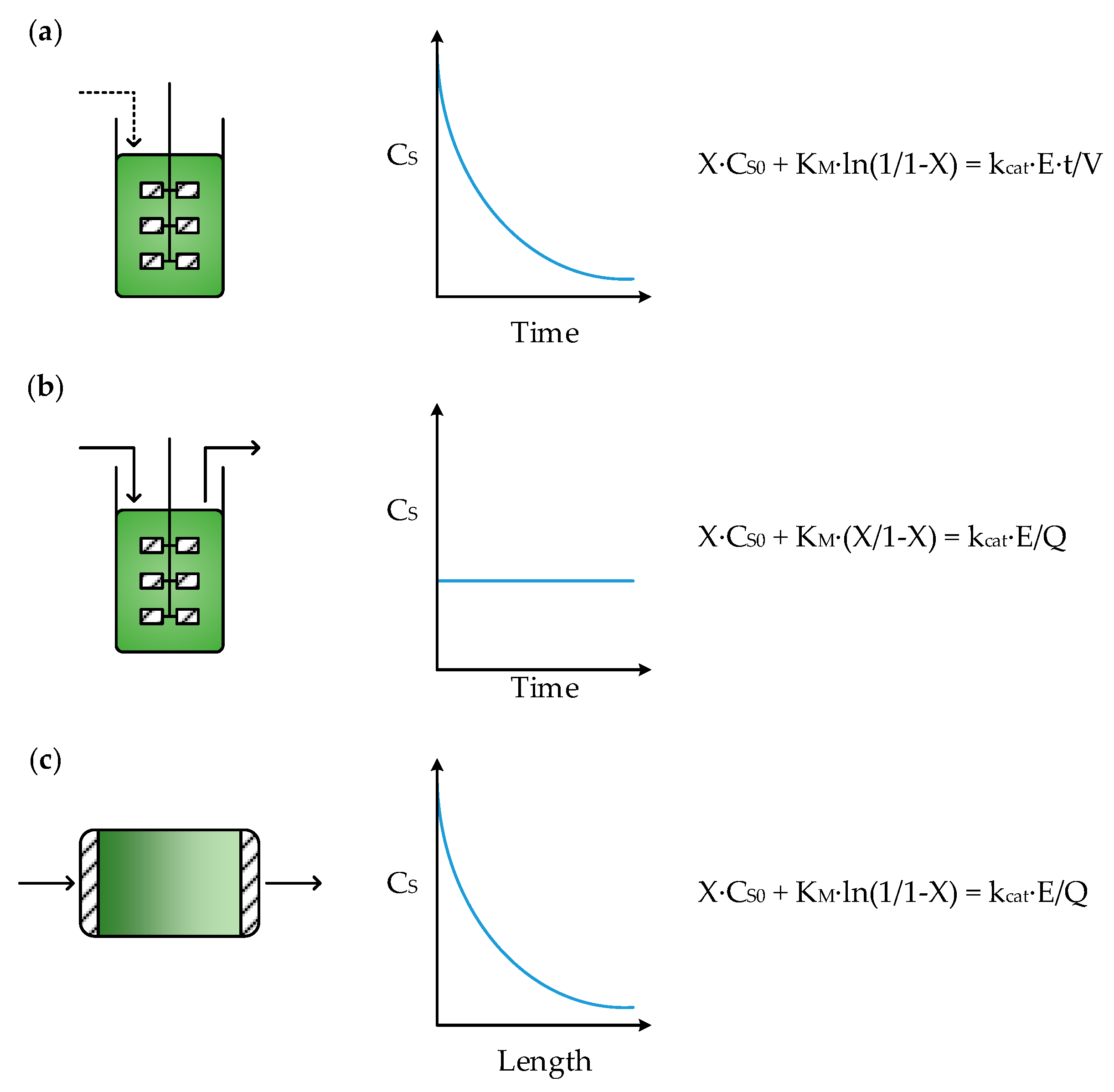
| Symbol | Definition | Unit |
| CS | Substrate concentration | mol L−1 |
| CS0 | Initial or inlet substrate concentration | mol L−1 |
| X | Fractional substrate conversion | - |
| t | Reaction time | s |
| V | Reactor volume | L |
| Q | Volumetric flowrate | L s−1 |
| KM | Substrate affinity constant | mol L−1 |
| kcat | Enzyme turnover number | s−1 |
| τ | Residence time | s |
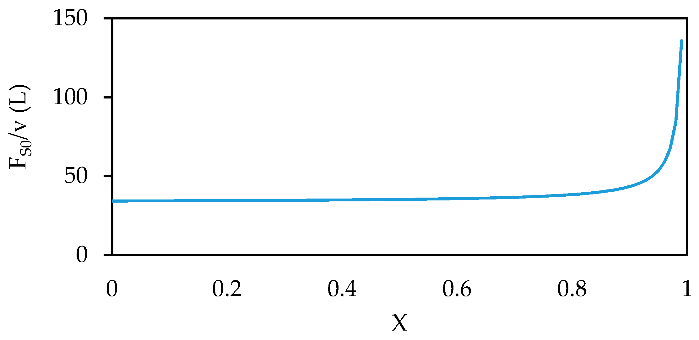
| FS0 | Inlet molar flowrate of substrate | mol s−1 |
References
- Porta, R.; Benaglia, M.; Puglisi, A. Flow Chemistry: Recent Developments in the Synthesis of Pharmaceutical Products. Org. Proc. Res. Dev. 2015, 20, 2–25. [Google Scholar] [CrossRef]
- Bornscheuer, U.T.; Huisman, G.W.; Kazlauskas, R.J.; Lutz, S.; Moore, J.C.; Robins, K. Engineering the third wave of biocatalysis. Nature 2012, 485, 185–194. [Google Scholar] [CrossRef] [PubMed]
- Strohmeier, G.A.; Pichler, H.; May, O.; Gruber-Khadjawi, M. Application of designed enzymes in organic synthesis. Chem. Rev. 2011, 111, 4141–4164. [Google Scholar] [CrossRef] [PubMed]
- Ghislieri, D.; Green, A.P.; Pontini, M.; Willies, S.C.; Rowles, I.; Frank, A.; Grogan, G.; Turner, N.J. Engineering an enantioselective amine oxidase for the synthesis of pharmaceutical building blocks and alkaloid natural products. J. Am. Chem. Soc. 2013, 135, 10863–10869. [Google Scholar] [CrossRef] [PubMed]
- Arnold, F.H. Directed Evolution: Bringing New Chemistry to Life. Angew. Chem. Int. Ed. 2018, 57, 4143–4148. [Google Scholar] [CrossRef] [PubMed]
- Ricca, E.; Brucher, B.; Schrittwieser, J.H. Multi-Enzymatic Cascade Reactions: Overview and Perspectives. Adv. Synth. Catal. 2011, 353, 2239–2262. [Google Scholar] [CrossRef]
- Chuaboon, L.; Wongate, T.; Punthong, P.; Kiattisewee, C.; Lawan, N.; Hsu, C.; Lin, C.; Bornscheuer, U.T.; Chaiyen, P. One-Pot Bioconversion of L-Arabinose to L-Ribulose in an Enzymatic Cascade. Angew. Chem. 2019, 10. [Google Scholar] [CrossRef]
- Aumala, V.; Mollerup, F.; Jurak, E.; Blume, F.; Karppi, J.; Koistinen, A.; Schuiten, E.; Voss, M.; Bornscheuer, U.; Deska, J.; et al. Biocatalytic production of amino-carbohydrates through oxidoreductase and transaminase cascades. ChemSusChem 2018. [Google Scholar] [CrossRef]
- Ma, S.K.; Gruber, J.; Davis, C.; Newman, L.; Gray, D.; Wang, A.; Grate, J.; Huisman, G.W.; Sheldon, R.A. A green-by-design biocatalytic process for atorvastatin intermediate. Green Chem. 2010, 12, 81–86. [Google Scholar] [CrossRef]
- Tamborini, L.; Fernandes, P.; Paradisi, F.; Molinari, F. Flow Bioreactors as Complementary Tools for Biocatalytic Process Intensification. Trends Biotechnol. 2018, 36, 73–88. [Google Scholar] [CrossRef] [PubMed]
- Jones, E.; McClean, K.; Housden, S.; Gasparini, G.; Archer, I. Biocatalytic oxidase: Batch to continuous. Chem. Eng. Res. Des. 2012, 90, 726–731. [Google Scholar] [CrossRef]
- Rudroff, F.; Mihovilovic, M.D.; Gröger, H.; Snajdrova, R.; Iding, H.; Bornscheuer, U.T. Opportunities and challenges for combining chemo- and biocatalysis. Nat. Catal. 2018, 1, 12–22. [Google Scholar] [CrossRef]
- Dawood, A.W.H.; Bassut, J.; de Souza, R.; Bornscheuer, U.T. Combination of the Suzuki-Miyaura Cross-Coupling Reaction with Engineered Transaminases. Chem. Eur. J. 2018, 24, 16009–16013. [Google Scholar] [CrossRef] [PubMed]
- Ringborg, R.H.; Pedersen, A.T.; Woodley, J.M. Automated Determination of Oxygen-Dependent Enzyme Kinetics in a Tube-in-Tube Flow Reactor. ChemCatChem 2017, 9, 3285–3288. [Google Scholar] [CrossRef] [PubMed]
- Bolivar, J.M.; Eisl, I.; Nidetzky, B. Advanced characterization of immobilized enzymes as heterogeneous biocatalysts. Catal. Today 2015, 259, 66–80. [Google Scholar] [CrossRef]
- Andrade, L.H.; Kroutil, W.; Jamison, T.F. Continuous flow synthesis of chiral amines in organic solvents: Immobilization of E. coli cells containing both omega-transaminase and PLP. Org. Lett. 2014, 16, 6092–6095. [Google Scholar] [CrossRef] [PubMed]
- Gasparini, G.; Archer, I.; Jones, E.; Ashe, R. Scaling Up Biocatalysis Reactions in Flow Reactors. Org. Process Res. Dev. 2012, 16, 1013–1016. [Google Scholar] [CrossRef]
- Woodley, J.M. Scale-Up and Development of Enzyme-Based Processes for Large-Scale Synthesis Applications. In Science of Synthesis: Biocatalysis in Organic Synthesis; Faber, K., Fessner, W.D., Turner, N.J., Eds.; Thieme: Stuttgart, Germany, 2015; Volume 3, pp. 515–546. [Google Scholar]
- Zhou, X.; Lü, S.; Xu, Y.; Mo, Y.; Yu, S. Improving the performance of cell biocatalysis and the productivity of xylonic acid using a compressed oxygen supply. Biochem. Eng. J. 2015, 93, 196–199. [Google Scholar] [CrossRef]
- Dennewald, D.; Hortsch, R.; Weuster-Botz, D. Evaluation of parallel milliliter-scale stirred-tank bioreactors for the study of biphasic whole-cell biocatalysis with ionic liquids. J. Biotechnol. 2012, 157, 253–257. [Google Scholar] [CrossRef] [PubMed]
- Zhang, J.; Fang, X.; Zhu, X.-L.; Li, Y.; Xu, H.-P.; Zhao, B.-F.; Chen, L.; Zhang, X.-D. Microbial lipid production by the oleaginous yeast Cryptococcus curvatus O3 grown in fed-batch culture. Biomass Bioenergy 2011, 35, 1906–1911. [Google Scholar] [CrossRef]
- Gomes, N.; Teixeira, J.A.; Belo, I. Fed-batch versus batch cultures of Yarrowia lipolytica for gamma-decalactone production from methyl ricinoleate. Biotechnol. Lett. 2012, 34, 649–654. [Google Scholar] [CrossRef] [PubMed]
- Lima-Ramos, J.; Neto, W.; Woodley, J.M. Engineering of Biocatalysts and Biocatalytic Processes. Top. Catal. 2014, 57, 301–320. [Google Scholar] [CrossRef]
- Tran, D.-T.; Chen, C.-L.; Chang, J.-S. Continuous biodiesel conversion via enzymatic transesterification catalyzed by immobilized Burkholderia lipase in a packed-bed bioreactor. Appl. Energ. 2016, 168, 340–350. [Google Scholar] [CrossRef]
- Xu, Y.; Nordblad, M.; Woodley, J.M. A two-stage enzymatic ethanol-based biodiesel production in a packed bed reactor. J. Biotechnol. 2012, 162, 407–414. [Google Scholar] [CrossRef] [PubMed]
- Mohr, S.; Fisher, K.; Scrutton, N.S.; Goddard, N.J.; Fielden, P.R. Continuous two-phase flow miniaturised bioreactor for monitoring anaerobic biocatalysis by pentaerythritol tetranitrate reductase. Lab A Chip 2010, 10, 1929–1936. [Google Scholar] [CrossRef] [PubMed]
- Britton, J.; Raston, C.L.; Weiss, G.A. Rapid protein immobilization for thin film continuous flow biocatalysis. Chem. Commun. 2016, 52, 10159–10162. [Google Scholar] [CrossRef]
- Pedersen, A.T.; de Carvalho, T.M.; Sutherland, E.; Rehn, G.; Ashe, R.; Woodley, J.M. Characterization of a Continuous Agitated Cell Reactor for Oxygen Dependent Biocatalysis. Biotechnol. Bioeng. 2017, 114, 1222–1230. [Google Scholar] [CrossRef]
- Valera, F.E.; Quaranta, M.; Moran, A.; Blacker, J.; Armstrong, A.; Cabral, J.T.; Blackmond, D.G. The flow’s the thing... or is it? Assessing the merits of homogeneous reactions in flask and flow. Angew. Chem. 2010, 49, 2478–2485. [Google Scholar] [CrossRef]
- Wegner, J.; Ceylan, S.; Kirschning, A. Ten key issues in modern flow chemistry. Chem. Commun. 2011, 47, 4583–4592. [Google Scholar] [CrossRef]
- Yuryev, R.; Strompen, S.; Liese, A. Coupled chemo(enzymatic) reactions in continuous flow. Beilstein J. Org. Chem. 2011, 7, 1449–1467. [Google Scholar] [CrossRef]
- Morales, M.; Dapsens, P.Y.; Giovinazzo, I.; Witte, J.; Mondelli, C.; Papadokonstantakis, S.; Hungerbühler, K.; Pérez-Ramírez, J. Environmental and economic assessment of lactic acid production from glycerol using cascade bio- and chemocatalysis. Energy Environ. Sci. 2015, 8, 558–567. [Google Scholar] [CrossRef]
- Groger, H.; Hummel, W. Combining the ‘two worlds’ of chemocatalysis and biocatalysis towards multi-step one-pot processes in aqueous media. Curr. Opin. Chem. Biol. 2014, 19, 171–179. [Google Scholar] [CrossRef] [PubMed]
- Adamo, A.; Beingessner, R.L.; Behnam, M.; Chen, J.; Jamison, T.F.; Jensen, K.F.; Monbaliu, J.M.; Myerson, A.S.; Revalor, E.M.; Snead, D.R.; et al. On-demand continuous-flow production of pharmaceuticals in a compact, reconfigurable system. Science 2016, 352, 61–67. [Google Scholar] [CrossRef]
- Wohlgemuth, R. Biocatalysis-key to sustainable industrial chemistry. Curr. Opin. Biotechnol. 2010, 21, 713–724. [Google Scholar] [CrossRef]
- Bordeaux, M.; Galarneau, A.; Fajula, F.; Drone, J. A regioselective biocatalyst for alkane activation under mild conditions. Angew. Chem. 2011, 123, 2123–2127. [Google Scholar] [CrossRef]
- Woodley, J.M. Protein engineering of enzymes for process applications. Curr. Opin. Chem. Biol. 2013, 17, 310–316. [Google Scholar] [CrossRef] [PubMed]
- Woodley, J.M. Integrating protein engineering with process design for biocatalysis. Phil. Trans. R. Soc. A 2017, 376. [Google Scholar] [CrossRef] [PubMed]
- Abu, R.; Woodley, J.M. Application of Enzyme Coupling Reactions to Shift Thermodynamically Limited Biocatalytic Reactions. ChemCatChem 2015, 7, 3094–3105. [Google Scholar] [CrossRef]
- Savile, C.K.; Janey, J.M.; Mundorff, E.C.; Moore, J.C.; Tam, S.; Jarvis, W.R.; Colbeck, J.C.; Krebber, A.; Fleitz, F.J.; Brands, J.; et al. Biocatalytic Asymmetric Synthesis of Chiral Amines from Ketones Applied to Sitagliptin Manufacture. Science 2010, 329, 305–309. [Google Scholar] [CrossRef]
- Planchestainer, M.; Contente, M.L.; Cassidy, J.; Molinari, F.; Tamborini, L.; Paradisi, F. Continuous flow biocatalysis: Production and in-line purification of amines by immobilised transaminase from Halomonas elongata. Green Chem. 2017, 19, 372–375. [Google Scholar] [CrossRef]
- Cerioli, L.; Planchestainer, M.; Cassidy, J.; Tessaro, D.; Paradisi, F. Characterization of a novel amine transaminase from Halomonas elongata. J. Molec. Catal. B Enzym. 2015, 120, 141–150. [Google Scholar] [CrossRef]
- Rakmai, J.; Cheirsilp, B. Continuous production of β-cyclodextrin by cyclodextrin glycosyltransferase immobilized in mixed gel beads: Comparative study in continuous stirred tank reactor and packed bed reactor. Biochem. Eng. J. 2016, 105, 107–113. [Google Scholar] [CrossRef]
- Tufvesson, P.; Fu, W.; Jensen, J.S.; Woodley, J.M. Process considerations for the scale-up and implementation of biocatalysis. Food Bioprod. Process. 2010, 88, 3–11. [Google Scholar] [CrossRef]
- Xue, R.; Woodley, J.M. Process technology for multi-enzymatic reaction systems. Bioresour. Technol. 2012, 115, 183–195. [Google Scholar] [CrossRef]
- Schmolzer, K.; Madje, K.; Nidetzky, B.; Kratzer, R. Bioprocess design guided by in situ substrate supply and product removal: Process intensification for synthesis of (S)-1-(2-chlorophenyl)ethanol. Bioresour. Technol. 2012, 108, 216–223. [Google Scholar] [CrossRef]
- Gruber, P.; Marques, M.P.C.; O’Sullivan, B.; Baganz, F.; Wohlgemuth, R.; Szita, N. Conscious coupling: The challenges and opportunities of cascading enzymatic microreactors. Biotechnol. J. 2017, 12. [Google Scholar] [CrossRef] [PubMed]
- Karande, R.; Schmid, A.; Buehler, K. Miniaturizing Biocatalysis: Enzyme-Catalyzed Reactions in an Aqueous/Organic Segmented Flow Capillary Microreactor. Adv. Synth. Catal. 2011, 353, 2511–2521. [Google Scholar] [CrossRef]
- Nordblad, M.; Gomes, M.D.; Meissner, M.P.; Ramesh, H.; Woodley, J.M. Scoping Biocatalyst Performance Using Reaction Trajectory Analysis. Org. Proc. Res. Dev. 2018, 22, 1101–1114. [Google Scholar] [CrossRef]
- Lima-Ramos, J.; Tufvesson, P.; Woodley, J.M. Application of environmental and economic metrics to guide the development of biocatalytic processes. Green Process Synth 2014, 3. [Google Scholar] [CrossRef]
- Doukyu, N.; Ogino, H. Organic solvent-tolerant enzymes. Biochem. Eng. J. 2010, 48, 270–282. [Google Scholar] [CrossRef]
- Lee, A.; Chaibakhsh, N.; Rahman, M.B.A.; Basri, M.; Tejo, B.A. Optimized enzymatic synthesis of levulinate ester in solvent-free system. Ind. Crop. Prod. 2010, 32, 246–251. [Google Scholar] [CrossRef]
- Luo, J.; Morthensen, S.T.; Meyer, A.S.; Pinelo, M. Filtration behavior of casein glycomacropeptide (CGMP) in an enzymatic membrane reactor: Fouling control by membrane selection and threshold flux operation. J. Membr. Sci. 2014, 469, 127–139. [Google Scholar] [CrossRef]
- Bezerra, R.M.; Neto, D.M.A.; Galvão, W.S.; Rios, N.S.; Carvalho, A.C.L.d.M.; Correa, M.A.; Bohn, F.; Fernandez-Lafuente, R.; Fechine, P.B.A.; de Mattos, M.C.; et al. Design of a lipase-nano particle biocatalysts and its use in the kinetic resolution of medicament precursors. Biochem. Eng. J. 2017, 125, 104–115. [Google Scholar] [CrossRef]
- Sheldon, R.A.; van Pelt, S. Enzyme immobilisation in biocatalysis: Why, what and how. Chem. Soc. Rev. 2013, 42, 6223–6235. [Google Scholar] [CrossRef] [PubMed]
- Popat, A.; Hartono, S.B.; Stahr, F.; Liu, J.; Qiao, S.Z.; Qing Max Lu, G. Mesoporous silica nanoparticles for bioadsorption, enzyme immobilisation, and delivery carriers. Nanoscale 2011, 3, 2801–2818. [Google Scholar] [CrossRef] [PubMed]
- Palomo, J.M.; Munoz, G.; Fernandez-Lorente, G.; Mateo, C.; Fernandez-Lafuente, R.; Guisan, J.M. Interfacial adsorption of lipases on very hydrophobic support (octadecyl–Sepabeads): Immobilization, hyperactivation and stabilization of the open form of lipases. J. Mol. Catal. B Enzym. 2002, 19–20, 279–286. [Google Scholar] [CrossRef]
- Rios, N.S.; Pinheiro, M.P.; dos Santos, J.C.; Fonseca, T.D.; Lima, L.D.; de Mattos, M.C.; Freire, D.M.; da Silva Júnior, I.J.; Rodríguez-Aguado, E.; Goncalves, L.R. Strategies of covalent immobilization of a recombinant Candida antarctica lipase B on pore-expanded SBA-15 and its application in the kinetic resolution of (R,S)-Phenylethyl acetate. J. Mol. Catal. B Enzym. 2016, 133, 246–258. [Google Scholar] [CrossRef]
- Magner, E. Immobilisation of enzymes on mesoporous silicate materials. Chem. Soc. Rev. 2013, 42, 6213–6222. [Google Scholar] [CrossRef]
- Manoel, E.A.; Dos Santos, J.C.; Freire, D.M.; Rueda, N.; Fernandez-Lafuente, R. Immobilization of lipases on hydrophobic supports involves the open form of the enzyme. Enzym. Microb. Technol. 2015, 71, 53–57. [Google Scholar] [CrossRef] [PubMed]
- Jesionowski, T.; Zdarta, J.; Krajewska, B. Enzyme immobilization by adsorption: A review. Adsorption 2014, 20, 801–821. [Google Scholar] [CrossRef]
- Matosevic, S.; Lye, G.J.; Baganz, F. Immobilised enzyme microreactor for screening of multi-step bioconversions: Characterisation of a de novo transketolase-omega-transaminase pathway to synthesise chiral amino alcohols. J. Biotechnol. 2011, 155, 320–329. [Google Scholar] [CrossRef] [PubMed]
- Nunes, M.A.; Rosa, M.E.; Fernandes, P.C.; Ribeiro, M.H. Operational stability of naringinase PVA lens-shaped microparticles in batch stirred reactors and mini packed bed reactors-one step closer to industry. Bioresour. Technol. 2014, 164, 362–370. [Google Scholar] [CrossRef] [PubMed]
- Sheldon, R.A. Cross-Linked Enzyme Aggregates as Industrial Biocatalysts. Org. Proc. Res. Dev. 2011, 15, 213–223. [Google Scholar] [CrossRef]
- Xu, D.Y.; Yang, Z. Cross-linked tyrosinase aggregates for elimination of phenolic compounds from wastewater. Chemosphere 2013, 92, 391–398. [Google Scholar] [CrossRef] [PubMed]
- Xu, D.-Y.; Chen, J.-Y.; Yang, Z. Use of cross-linked tyrosinase aggregates as catalyst for synthesis of l-DOPA. Biochem. Eng. J. 2012, 63, 88–94. [Google Scholar] [CrossRef]
- Lage, F.A.; Bassi, J.J.; Corradini, M.C.; Todero, L.M.; Luiz, J.H.; Mendes, A.A. Preparation of a biocatalyst via physical adsorption of lipase from Thermomyces lanuginosus on hydrophobic support to catalyze biolubricant synthesis by esterification reaction in a solvent-free system. Enzym. Microb. Technol. 2016, 84, 56–67. [Google Scholar] [CrossRef]
- Manoel, E.A.; Ribeiro, M.F.P.; dos Santos, J.C.S.; Coelho, M.A.Z.; Simas, A.B.C.; Fernandez-Lafuente, R.; Freire, D.M.G. Accurel MP 1000 as a support for the immobilization of lipase from Burkholderia cepacia: Application to the kinetic resolution of myo -inositol derivatives. Process Biochem. 2015, 50, 1557–1564. [Google Scholar] [CrossRef]
- Kazi, F.K.; Fortman, J.A.; Anex, R.P.; Hsu, D.D.; Aden, A.; Dutta, A.; Kothandaraman, G. Techno-economic comparison of process technologies for biochemical ethanol production from corn stover. Fuel 2010, 89, S20–S28. [Google Scholar] [CrossRef]
- Li, S.; Yang, X.; Yang, S.; Zhu, M.; Wang, X. Technology prospecting on enzymes: Application, marketing and engineering. Comput. Struct. Biotechnol. J. 2012, 2, e201209017. [Google Scholar] [CrossRef]
- Chapman, J.; Ismail, A.; Dinu, C. Industrial Applications of Enzymes: Recent Advances, Techniques, and Outlooks. Catalysts 2018, 8, 238. [Google Scholar] [CrossRef]


© 2019 by the authors. Licensee MDPI, Basel, Switzerland. This article is an open access article distributed under the terms and conditions of the Creative Commons Attribution (CC BY) license (http://creativecommons.org/licenses/by/4.0/).
Share and Cite
Lindeque, R.M.; Woodley, J.M. Reactor Selection for Effective Continuous Biocatalytic Production of Pharmaceuticals. Catalysts 2019, 9, 262. https://doi.org/10.3390/catal9030262
Lindeque RM, Woodley JM. Reactor Selection for Effective Continuous Biocatalytic Production of Pharmaceuticals. Catalysts. 2019; 9(3):262. https://doi.org/10.3390/catal9030262
Chicago/Turabian StyleLindeque, Rowan M., and John M. Woodley. 2019. "Reactor Selection for Effective Continuous Biocatalytic Production of Pharmaceuticals" Catalysts 9, no. 3: 262. https://doi.org/10.3390/catal9030262
APA StyleLindeque, R. M., & Woodley, J. M. (2019). Reactor Selection for Effective Continuous Biocatalytic Production of Pharmaceuticals. Catalysts, 9(3), 262. https://doi.org/10.3390/catal9030262