Article

Insight into the Microstructure and Deactivation Effects on Commercial NiMo/γ-Al2O3 Catalyst through Aberration-Corrected Scanning Transmission Electron Microscopy

Research Institute of Petroleum Processing, SINOPEC, Beijing 100083, China
*
Authors to whom correspondence should be addressed.
Catalysts 2019, 9(10), 810; https://doi.org/10.3390/catal9100810
Submission received: 8 September 2019 / Revised: 19 September 2019 / Accepted: 22 September 2019 / Published: 27 September 2019
(This article belongs to the Section Catalytic Materials)

Abstract

:
Atom-resolved microstructure variations and deactivation effects on the commercial NiMo/γ-Al2O3 catalysts were revealed by aberration-corrected scanning transmission electron microscope (Cs-STEM) equipped with enhanced energy dispersive X-ray spectroscopy (EDS). Structural information parallel to and vertical to the electron beam provides definitive insight toward an understanding of structure–activity relations. Under the mild to harsher reaction conditions, “fragment” structures (like metal single atoms, metal clusters, and nanoparticles) of commercial NiMo/γ-Al2O3 catalysts, gradually reduces, while MoS2 nanoslabs get longer and thinner. Such a result about active slabs leads to the reduction in the number of active sites, resulting in a significant decrease in activity. Likewise, the average atomic ratio of promoter Ni and Ni/(Mo + S) ratio of slabs decrease from 2.53% to 0.45% and from 0.0788 to 0.0326, respectively, by means of EDS under the same conditions stated above, reflecting the weakening of the promotional effect. XPS result confirms the existence of NixSy species in deactivated catalysts. This could be ascribed to the Ni segregation from active phase. Furthermore, statistical data give realistic coke behaviors associated with the active metals. With catalytic activity decreasing, the coke on the active metals regions tends to increase faster than that on the support regions. This highlights that the commercial NiMo/γ-Al2O3 catalyst during catalysis is prone to produce more coke on the active metal areas.

Graphical Abstract

1. Introduction

Recently, the aberration-corrected scanning transmission electron microscope (Cs-STEM) has attracted continuing interest due to its atomic-scale features [1,2,3,4,5]. The detection mode of the Cs-STEM high-angle annular dark-field (Cs-STEM-HAADF) has been proven to be extremely valuable for characterizing supported catalysts since catalytic reactions are extremely sensitive to structures. The Cs-STEM-HAADF mode, in which it could chemically discriminate between elements by a scattering angle that scales with atomic number (~Z1.7) [6], is favorable for observing the metal element deposited on the support with lower Z. For example, individual single atoms and metal clusters/nanoparticles are directly imaged, and the crystal structures of the support are also clearly revealed simultaneously in Pt/γ-Al2O3, Pt/carbon, and Pd/ZnO catalysts [7]. More recently, Helveg et al. [8] investigated the MoS2 active phase on graphite in supported hydrotreating catalysts and successfully observed the lateral single-layer image of MoS2 slab, giving a basis for further study on the structure-dependent catalytic activity for hydrotreating catalysts.
For many earlier studies, the atomic scale structure of active phase on supported hydrotreating catalysts was investigated by scanning tunneling microscopy (STM) [2,9,10,11,12]; in this case, gold or graphite is often used as a support of the sulfide active phase structures since a weakly interaction exists between them. However, in industrial applications, γ-Al2O3 with a large specific surface area and abundant porosity is often used as the support to provide reaction channels and improve the dispersion of active components. The difficulty for many years is to understand in detail the structure-dependent catalytic activity of Al2O3-supported catalysts since direct atom-resolved insight was not previously available. However, the Cs-STEM-HAADF mode has opened up the possibility of studying commercial γ-Al2O3 supported catalysts with atomic-level resolution and sensitivity. Importantly, the smaller probe of Cs-STEM makes it possible to roundly delve the relationship of active phase with respect to their surface structures. Previous studies have shown that the size of the MoS2/WS2 slabs and stacks in hydroprocessing catalysts would be changed under the reaction conditions by the TEM technique [13,14,15,16], and small size MoS2 may have a better catalytic activity [17]. It is, therefore, still a striking work to exactly track the microstructure variations of NiMo/Al2O3 catalyst during catalysis by the Cs-STEM-HAADF mode.
On the other hand, catalyst deactivation is a serious problem during catalytic reaction. It is generally accepted that the variation of active phase structure and the coke deposition are the main reasons leading to catalyst deactivation. Eijsbouts et al. [13] pointed that the formation of Ni3S2 takes place in deactivated NiMo/Al2O3 by high resolution TEM, which lowers the catalytic activity. However, a similar phenomenon is not as well understood for direct detection variation in Ni content of the active slabs during catalysis. Beyond that, taking into account the coke deposition, numerous studies have been devoted to elucidating the coking location and coking mechanism in hydrotreating catalysts [18,19,20,21,22,23]. The two points of coke deposition have been the subject of much controversy so far. Thus, it is necessary to investigate the deactivation effects on commercial NiMo/γ-Al2O3 catalysts in order to get a clean result to optimize the preparation condition as well to prolong on-stream efficiency which improves the overall process economics. Then, it is not surprising given the designed commercial NiMo/γ-Al2O3 catalysts under different treatment to elucidate the deactivation effects in this work.
The designed strategy used here is to reproduce catalyst deactivation of industrial application in laboratory as much as possible through controlling the unit operating temperature and the quality of feedstock due to typical commercial hydrotreating catalysts having a lifetime of 2–4 years in industrial applications. It has been previously shown that catalysts in laboratory could accelerate deactivation during relatively short periods at a higher unit operating temperature and by using more inferior feedstock [24,25,26,27]. Herein, the scope of the current work involves the following three aspects: (i) characterizing the atomic-resolution structure of the commercial NiMo/γ-Al2O3 catalyst by the Cs-STEM-HAADF mode; (ii) investigating the structural variations with the decreasing of catalytic activity; and (iii) investigating the deactivation effects from the aspects of the Ni promotional effect and coke deposition.

2. Results and Discussion

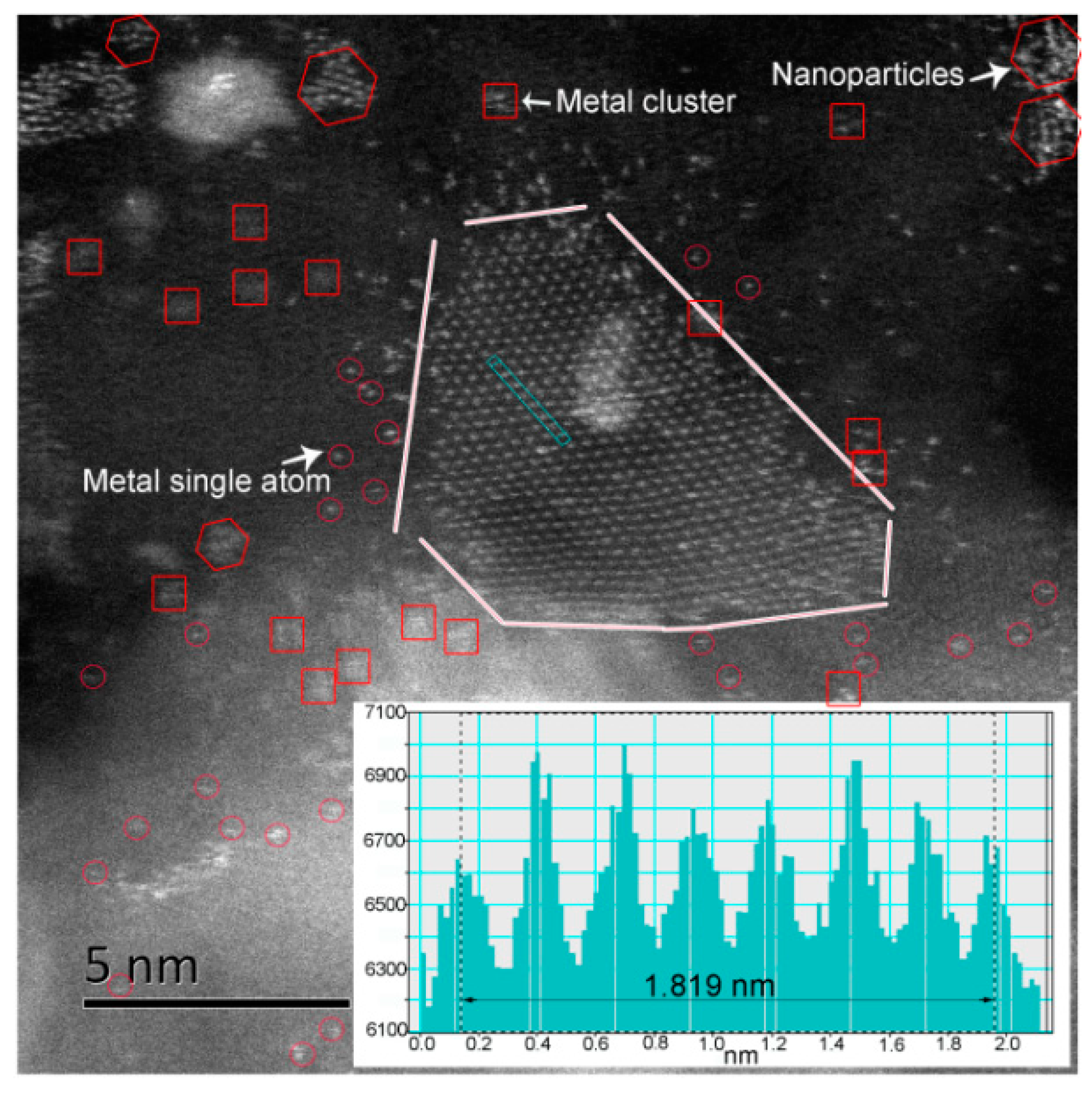
2.1. Atomic-Resolution Microstructure

The Cs-STEM-HAADF mode was used to analyze the 2D microstructures of commercial NiMo/γ-Al2O3 catalyst. Figure 1 shows the atomic-scale structure of the fresh sulfide catalyst (Cat A). It is clearly seen that the active phase slabs are perpendicular to the electron beam. Such a distinctive microstructure is rarely visualized by the conventional TEM mode, though it has been predicted in hydrotreating catalysts [3,9,28]. The interatomic spacing of Mo–Mo as revealed by the line profile (see the inset of Figure 1) is 2.60 Å, which is slightly smaller than the Mo–Mo interatomic distance (2.70 Å) of unsupported MoS2 catalysts [29]. This can be attributed to the unevenness of γ-Al2O3. Furthermore, the observed slab shape is a roughly truncated triangle shape, highlighting the effect of the addition of Ni promoter. Precisely, most active slabs are irregular due to the curl and a lot of defects are not the ones observed previously by STM for MoS2 supported on a thin graphite sheet or Au(111) [9,30]. The shape heterogeneity of slabs is intrinsically linked to the complexity of γ-Al2O3 in the commercial catalysts and catalyst preparation method used here.
A more detailed analysis of the image shows some “fragment” structures, which also could not be detected by the conventional TEM mode. Here, the “fragment” structures are divided into three genres. We define the nanoparticles with a diameter between 0.5 and 2.0 nm that are relatively stable but have not yet formed a relatively regular active phase structures, shown as hexagons in Figure 1. Atoms in the rectangle of Figure 1 with a size less than 0.5 nm are called metal clusters. Metal single atoms are pointed by the red circle in Figure 1. Compared to the Ni(Co)–Mo–S mode proposed by Topsøe [3,9,28], the observed striking atomic-scale structures in commercial NiMo/γ-Al2O3 catalysts may provide an insight into the correlation between catalytic activity and microstructure.

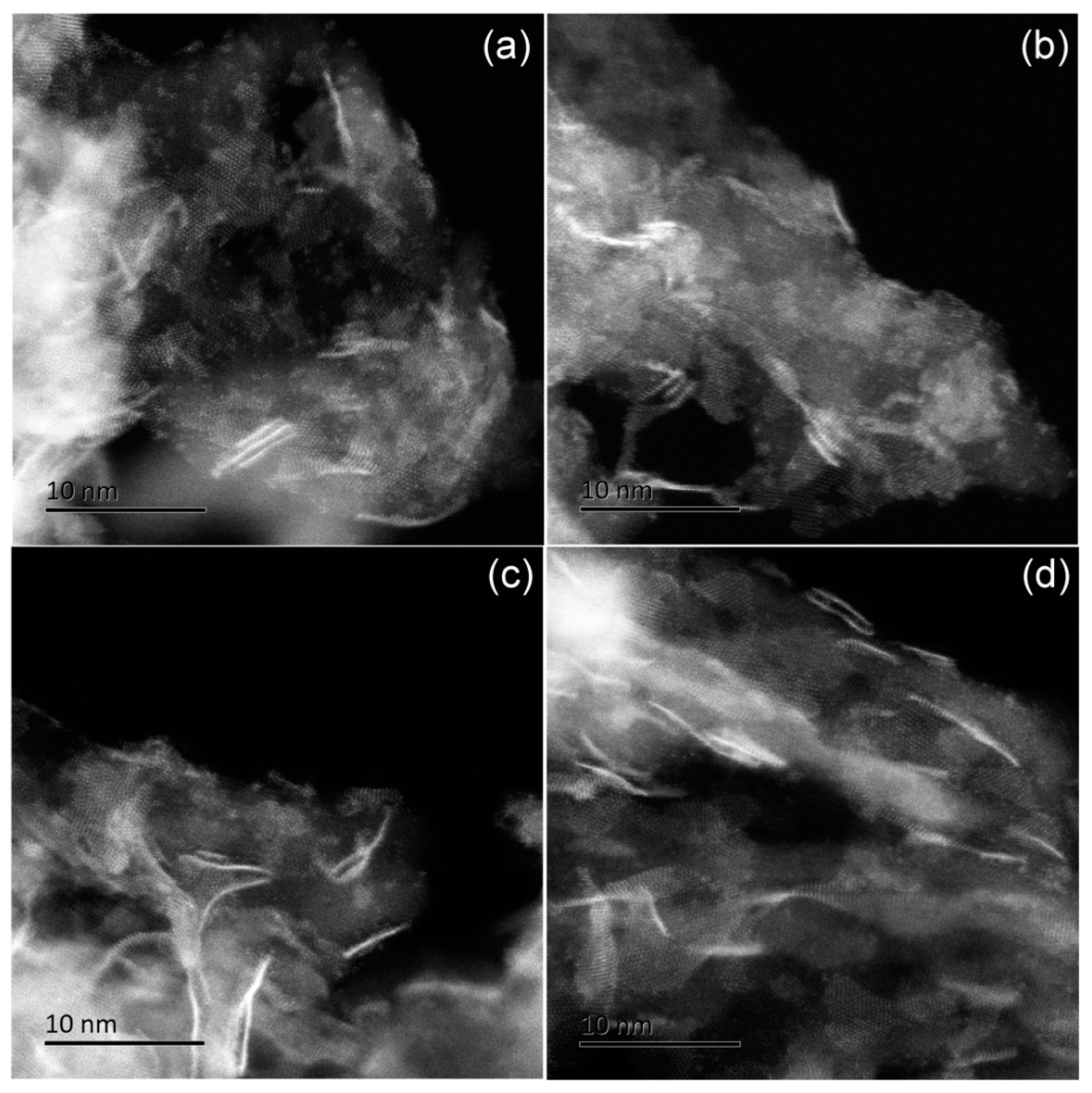
2.2. Structural Variations with the Decreasing of Catalytic Activity

Given that the catalytic activity is sensitive to microstructures, thus, the atomic-scale structures of the four commercial NiMo/γ-Al2O3 catalysts were characterized using the Cs-STEM-HAADF mode, which is shown in Figure 2. More precisely, before the characterization, the catalytic activity was evaluated. The expected activity information was acquired in Table 1. In Figure 2a, Cat A presents the typical multilayered slabs active phase structure and the “fragment” structures. The average size of slabs ( L ¯ ) of Cat A has been measured to be 3.91 nm by an average of 206 slabs (see Table S1 in the Supplementary material) from several HAADF images. A similar inspection of Cat B was performed, as illustrated in Figure 2b. The observed structures are in analogy with Cat A, and the length L ¯ (4.19 nm) of Cat B also approximates to the one of Cat A, inferring a mild reaction condition that has no significant impact on catalytic microstructures. However, in the case of Cat C (see Figure 2c), differences in morphologies were mapped. Looking more broadly across Figure 2c, it is evident that fewer “fragment” structures and larger multilayered ( L ¯ = 5.20 nm) or monolayer active phase structures have been detected on the alumina support. The variations are linked to the growth of slabs under harsh conditions. Of particular interest is more and more monolayer slabs with a strong increase in the size ( L ¯ = 6.03 nm) that exist on the alumina support under harsher conditions, as shown in Figure 2d and Table S1, highlighting that the monolayer structures are unfavorable to raise the activity of the NiMo/γ-Al2O3 catalyst. This is inconsistent with the opinion reported by Topsøe et al. [31], who used multiple spectral studies to illustrate the strong interactions between the monolayer and high-surface area alumina via Mo–O–Al linkages located at the edges, thus leading to low catalytic activity. From the above, the change trends of the size of MoS2 slabs and stacks for commercial NiMo/γ-Al2O3 catalyst using the Cs-STEM-HAADF mode are in analogy with previous works by TEM [13,14,15,16], while the observed difference is the variation of “fragment” structures once the catalyst was exposed to harsher reaction conditions from the mild one in this work, which may be partial resource for the larger slabs in Cat C and Cat D. In general, the distinction in overall microstructure variations for the four catalysts is presumably a reflection of the differences in catalytic activity of the NiMo/γ-Al2O3 catalyst.

2.3. Deactivation Effects

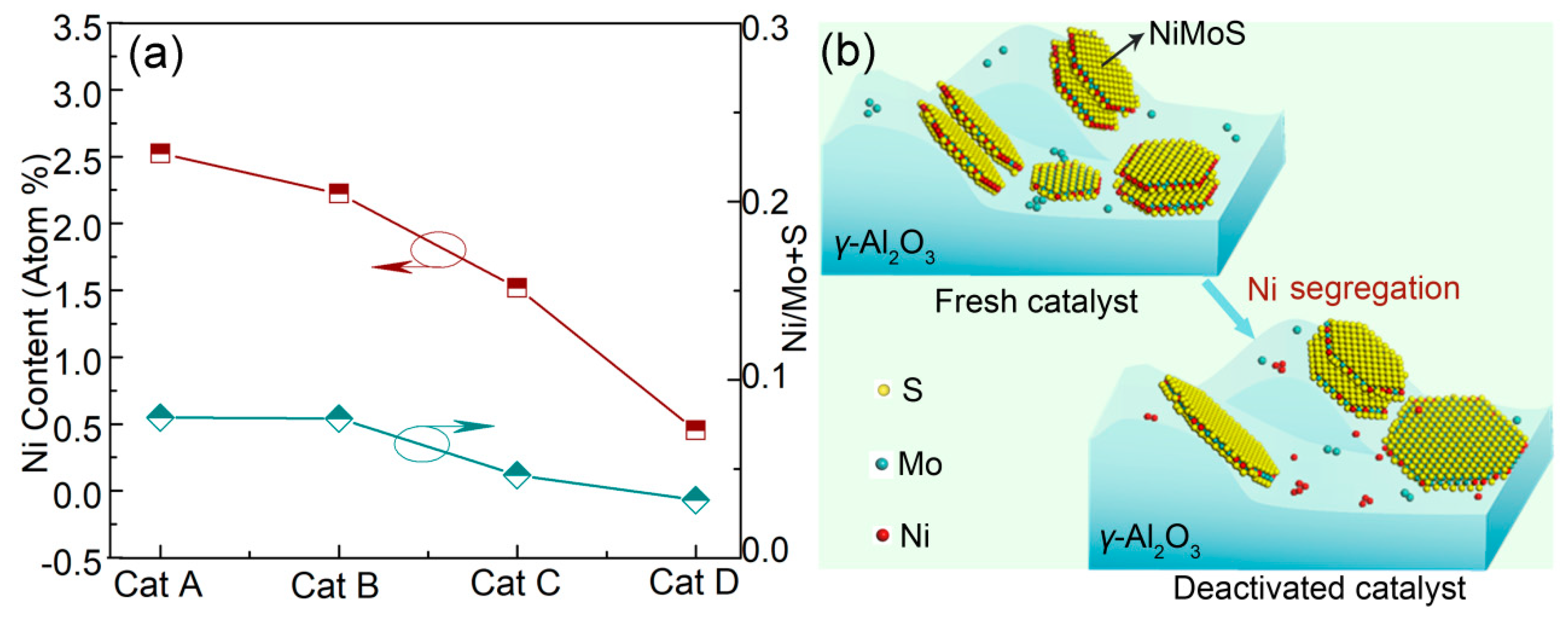
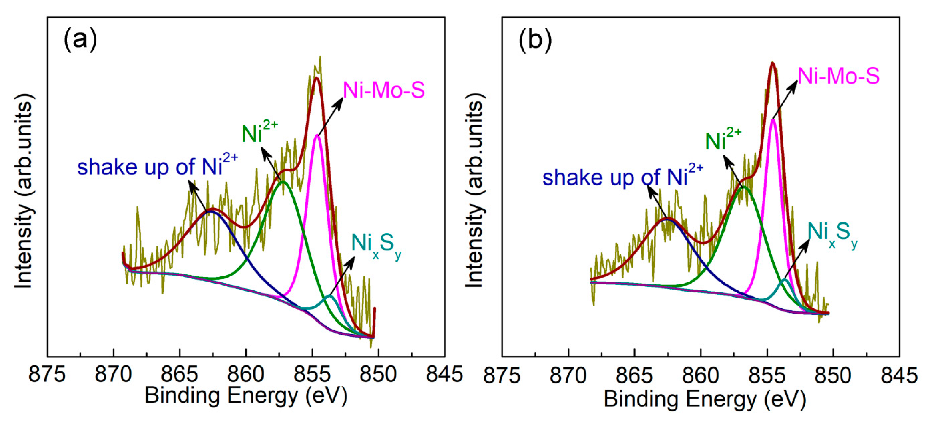
2.3.1. Ni Segregation from the Active Phase

Note that a precise analysis of the identification of Ni by imaging in the active slabs is not possible in our case owing to complexity of γ-Al2O3. In order to explore the variations of promoter Ni under the mild to harsher reaction conditions, the enhanced energy dispersive X-ray spectroscopy (EDS) was performed on the target specific areas of interest, which could provide the precise and reliable chemical information for the NiMo/γ-Al2O3 catalyst. Figure 3 shows an STEM-HAADF image and corresponding selected area for Cat A to evaluate the stoichiometric changes of promoter Ni as a function of different catalysts. Boxed regions in Figure 3a have been classified into two types, including regions of active metals (Type I) and regions of support (Type II). The corresponding typical EDS spectra of the two district types are shown in Figure 3b,c, respectively. Similar investigation approaches are also carried out for other three catalysts, which are presented in Figures S1–S3. Based on the EDS results, the mean atomic ratio of Ni on Type I regions in Cat A was calculated to be 2.53%, as shown in Table 2. After mild reaction there appears to be only a slightly decrease in the mean Ni atomic ratio, which further drops down with the deactivation of the catalyst. The line profile (Figure 4a) intuitively shows the variation of Ni atomic ratio. Accordingly, one can also note the same variation in the ratio of Ni/Mo+S during the catalyst use. This illustrates the weakness of promotional effect from the fresh NiMo/γ-Al2O3 catalyst to the deactivated ones, as schematically shown in Figure 4b. The above results provide a visualized and reliable understanding about the deactivation behavior by means of STEM-HAADF and EDS.
Of particular interest is that in Cat C and Cat D, the Ni element was detected in some nanoparticles by EDS. We speculate that the promoter Ni exists as NixSy crystals after segregation from the active phase. For hydrotreating catalysts, the X-ray photoelectron spectroscopy (XPS) technique has been among the tools most often used to obtain chemical states information on the promoter atoms in hydrotreating catalysts [32,33,34,35]. Therefore, XPS was performed for the catalysts in order to verify our speculation. From the detailed analysis of Ni 2p XPS spectra, different Ni species could be distinguished. For Cat A and Cat B, there is no signal of nickel sulfide (see Figure S4). However, from Figure 5, NixSy exhibits a distinct peak at 853.6 eV in deactivated catalysts (Cat C and Cat D), which is about 1.0 eV lower than that of Ni–Mo–S. Such a result has given a definite evidence for the presence of NixSy in deactivated catalysts.

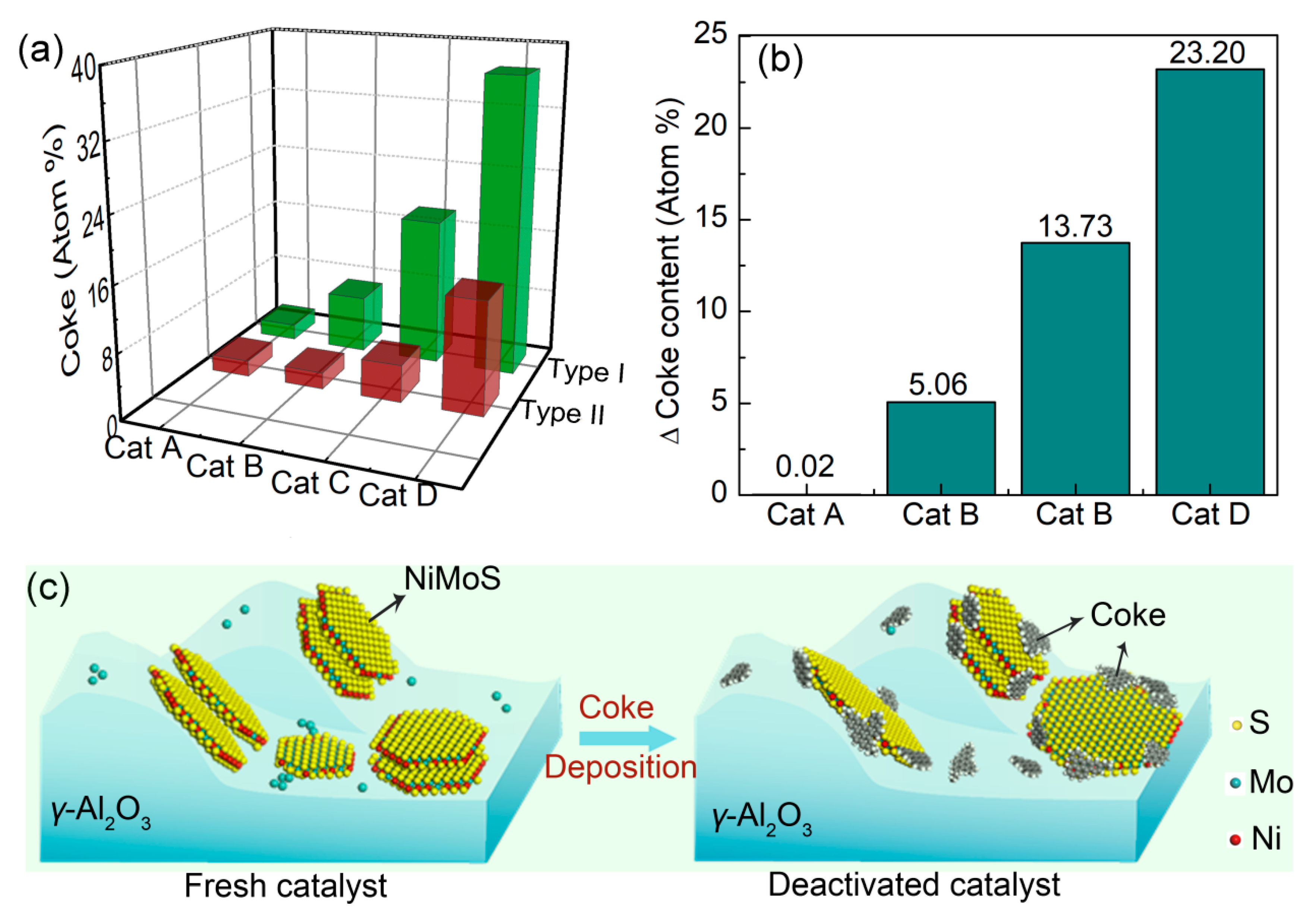
2.3.2. Coke Deposition

Coke deposition on hydrotreating catalysts is also one of the main reasons of deactivation. To understand the variation behaviors of coke on the NiMo/γ-Al2O3 catalyst in the process of using, EDS spectra were collected for multiple individual boxed regions in terms of two types, as shown in Figure 3a. Active metals’ dependence on coke and support dependence of coke were investigated, as depicted in Figure 6a,b. It can be seen that the coke deposition was closely correlated to the regional difference. On the Type I regions, the average atomic ratio of carbon on these four catalysts was 1.99%, 7.10%, 18.35%, and 37.13%, respectively, which illustrates that the lower the catalytic activity is, the more coke (carbon) is formed. Further, the values of carbon atomic ratio on the deactivated catalysts (Cat C and Cat D) are much higher than that on the fresh one (Cat A). In addition, we can also notice that the trend of coke deposition on Type II regions is consistent with the one on Type I regions. Their average contents of coke for Cat A, Cat B, Cat C, and Cat D were 1.98%, 2.04%, 4.61%, and 13.92%, respectively (see Figure 6b). The above result also directly corroborates the fact that coke is an important factor leading to the reduction of catalyst activity.
Moreover, comparison of the coke contents on Type I and Type II regions elicits two interesting features: (1) no difference of coke deposition between Type I and Type II regions for Cat A; and (2) a higher coke deposition on the Type I regions for nonfresh catalysts (Cat B, Cat C, Cat D). Such features propose that the active metal regions accumulate coke more rapidly than the alumina support; thus, the catalytic activity is limited by the restricted access to active phase structures, which leads to a drop in catalytic activity, as schematically displayed in Figure 6c. However, as reported earlier [20], γ-Al2O3 support serves as a preferential coke deposition site for the NiMo/γ-Al2O3 catalyst due to the self-cleaning process by the active hydrogen phase. Ongoing work in our laboratory has not produced results corroborating their opinion. This is an important finding that the coke preferentially deposits on active metals in commercial NiMo/γ-Al2O3 catalyst during catalysis.

3. Materials and Methods

3.1. Catalyst Preparations

The catalyst used was a commercial NiMo/γ-Al2O3, with 4.0 wt.% of NiO and 22.0 wt.% of MoO3. Prior to being used, the catalyst was sulfided in kerosene containing 2.0 wt.% of dimethyldisulfide (DMDS) at 6.4 MPa, 593 K for 48 h, and the resulting fresh sulfide sample was denoted as Cat A. Then, Cat A was treated in a straight-run gas oil (SRGO, S: 1.13%, N: 102 ppm) at 6.4 MPa, 613 K for 48 h to obtain the second sample denoted as Cat B. Afterwards, Cat B was treated by two accelerated deactivation treatments successively, that is, first using SRGO blending with 50.0 wt.% fluid catalytic cracker light cycle oil (LCO) as the feedstock at 3.2 MPa, 643 K for 144 h, and then using 100% LCO (S: 1.13%, N: 703 ppm) as the feedstock at 3.2 MPa, 668 K for 144 h. The corresponding prepared samples were denoted as Cat C and Cat D. From Cat B to Cat D, by increasing the unit operating temperature and using more inferior feedstock, the activity and the microstructure of the catalyst would undergo an obvious change, thus facilitating rational study of the microstructure and deactivation effects on commercial NiMo/γ-Al2O3 catalyst through Cs-STEM.

3.2. Catalytic Activity Evaluation

The catalytic activity tests of the above four catalysts were carried out in a continuous flow fixed-bed reactor under a pressure of 6.4 MPa with a temperature of 613 K. The specific reaction conditions were the catalyst loading of 20 mL, SRGO (S: 1.13%, N: 102 ppm) as the feed, the feed flow rate of 40 mL/h, and the hydrogen flow rate of 12 L/h. The sulfur content and nitrogen content of liquid effluents were analyzed until a target research steady-state was achieved. Finally, the hydrodesulfurization (HDS) activity and hydrodenitrogenation (HDN) activity of the catalysts were calculated as follows:
HDS conversion (XS), % = [(SfeedSproduct)/Sfeed] × 100
where Sfeed and Sproduct denote the sulfur content in the feed and products, respectively.
HDN conversion (XN), % = [(NfeedNproduct)/Nfeed] × 100
where Nfeed and Nproduct denote the nitrogen content in the feed and products, respectively.

3.3. Catalyst Characterizations

The Cs-STEM-HAADF technique provides unparalleled structure information at an atomic scale for γ-Al2O3 supported catalyst. The catalytic specimens were prepared by depositing drops of cyclohexane suspensions on 200 mesh holey carbon Nylon grids for images and chemical analysis. Deposited grids were then inserted into the sample chamber of electron microscope equipped with a probe-corrector (JEOL, Tokyo, Japan, ARM200F). For the Cs-STEM characterization, the specimens were analyzed at 200 kV. The probe size used for acquiring the HAADF image was 8C. The condenser lens (CL) aperture sizes were 150 μm (CL1) and 40 μm (CL2). The camera length used in the HAADF mode was 8 cm. EDS analysis of the selected area was performed by a windowless silicon drift detector (SDD), which can boost the collection efficiency of light element (i.e., C, N, O, etc.) detection. On this occasion, the probe size was 5C. In order to select areas precisely, spectra were collected at 6M magnification. The collection times were sustained below 20 s to avoid electron beam damage. XPS spectra (Thermo Fischer, Waltham, MA, USA, -VG ESCALAB 250) were acquired using a 150 W monochromatic Al Ka source to characterize Ni species. The Al 2p peak at 74.7 eV from the support Al2O3 was used as the reference. To precisely provide the information about Ni species, a narrow scan was performed with a pass energy of 30 eV to obtain high-resolution spectra. The obtained XPS spectra were fitted using Avantage 5.952 software provided by Thermo Fisher-VG Corporation.

4. Conclusions

In summary, the aberration-corrected STEM-HAADF technique was successfully employed to explore the structure variations with corresponding catalytic activity. The “fragment” structures, such as metal single atoms, metal clusters and nanoparticles, in sulfuring Cat A could be clearly observed, which cannot be obtained using conventional TEM. These “fragment” structures are gradually reduced during catalytic reaction. Meanwhile, the active slabs get larger and thinner. Such a result leads to a reduction in the number of active sites, thereby leading to a significant reduction in activity. From the aspect of the promotional effect, the extents of the average atomic ratio of Ni and Ni/(Mo + S) ratio of slabs decrease from fresh sulfide to a deactivated state, denoting weakening of the promotional effect in catalytic reaction. The stripped Ni has been confirmed to exist in terms of NixSy species in the deactivated catalyst by the XPS technique. On the other hand, the extent of coke deposition on the active phase regions and support regions has been found to increase with the decrease in catalytic activity through the EDS statistical data. However, the coke on the active metals regions tends to increase faster than that in the support regions. This highlights that the commercial NiMo/γ-Al2O3 catalyst during catalysis is prone to produce more cokes on the active metal areas. Our investigation in commercial hydrotreating catalysts reveals that the microstructure effect and promotional effect, as well as the coke deposition are all dependent on the catalytic states, which will be greatly helpful for the optimal use of the catalysts and exploration of catalytic mechanism.

Supplementary Materials

The following are available online at https://www.mdpi.com/2073-4344/9/10/810/s1, Table S1: The average slabs length ( L ¯ ) and average stacking degree ( N ¯ ) of four NiMo/γ-Al2O3 catalysts. Figures S1–S3: District types on STEM-HAADF images of Cat B, Cat C, and Cat D, and corresponding EDS spectra, respectively. Figure S4: Peak-fitting of Ni 2p XPS spectra of Cat A.

Author Contributions

W.H. (Wenhui He), A.Z., and A.H. conceived, designed and performed the experiments; W.H. (Wei Han) and L.Z. analyzed the data and assisted in manuscript editing; G.X., L.Q., W.W., and Y.X. provided suggestions; W.H. (Wenhui He) wrote the paper.

Funding

This research was funded by National Key Research and Development Program of China (Grant No. 2017YFB0306603). And The APC was funded by Research Institute of Petroleum Processing, SINOPEC.

Conflicts of Interest

The authors declare no conflict of interest.

References

  1. Girleanu, M.; Alphazan, T.; Boudene, Z.; Bonduelle-Skrzypczak, A.; Legens, C.; Gay, A.S.; Copret, C.; Ersen, O.; Raybaud, P. Magnifying the morphology change induced by a nickel promoter in tungsten (IV) sulfide industrial hydrocracking catalyst: A HAADF-STEM and DFT Study. ChemCatChem 2014, 6, 1594–1598. [Google Scholar] [CrossRef]
  2. Allard, L.F.; Borisevich, A.; Deng, W.; Si, R.; Flytzani-Stephanopoulos, M.; Overbury, S.H. Evolution of gold structure during thermal treatment of Au/FeOx catalysts revealed by aberration-corrected electron microscopy. J. Electron Microsc. 2009, 58, 199–212. [Google Scholar] [CrossRef] [PubMed]
  3. Besenbacher, F.; Brorson, M.; Clausen, B.S.; Helveg, S.; Hinnemann, B.; Kibsgaard, J.; Lauritsen, J.V.; Moses, P.G.; Nørskov, J.K.; Topsøe, H. Recent STM, DFT and HAADF-STEM studies of sulfide-based hydrotreating catalysts: Insight into mechanistic, structural and particle size effects. Catal. Today 2008, 130, 86–96. [Google Scholar] [CrossRef]
  4. Castro-Guerrero, C.F.; Deepak, F.L.; Ponce, A.; Cruz-Reyes, J.; Valle Granados, M.D.; Fuentes-Moyado, S.; Galva’n, D.H.; Jose’-Yacama’n, M. Structure and catalytic properties of hexagonal molybdenum disulfide nanoplates. Catal. Sci. Technol. 2011, 1, 1024–1031. [Google Scholar] [CrossRef]
  5. Baubet, B.; Girleanu, M.; Gay, A.S.; Taleb, A.L.; Moreaud, M.; Wahl, F.; Delattre, V.; Devers, E.; Hugon, A.; Ersen, O.; et al. Quantitative Two-Dimensional (2D) Morphology—Selectivity relationship of CoMoS nanolayers: A combined high-resolution high-angle annular dark field scanning transmission electron microscopy (HR HAADF- STEM) and Density Functional Theory (DFT) Study. ACS Catal. 2016, 6, 1081–1092. [Google Scholar] [CrossRef]
  6. Nellist, P.D.; Pennycook, S.J. Direct imaging of the atomic configuration of ultradispersed catalysts. Science 1996, 274, 413–415. [Google Scholar] [CrossRef]
  7. Liu, J. Aberration-corrected scanning transmission electron microscopy in single-atom catalysis: Probing the catalytically active centers. Chin. J. Catal. 2017, 38, 1460–1472. [Google Scholar] [CrossRef]
  8. Zhu, Y.Y.; Ramasse, Q.M.; Brorson, M.; Moses, P.G.; Hansen, L.P.; Kisielowski, C.F.; Helveg, S. Visualizing the stoichiometry of industrial-style Co-Mo-S catalysts with single-atom sensitivity. Angew. Chem. Int. Ed. 2014, 53, 10723–10727. [Google Scholar] [CrossRef] [PubMed]
  9. Lauritsen, J.V.; Kibsgaard, J.; Olesen, G.H.; Moses, P.G.; Hinnemann, B.; Helveg, S.; Nørskov, J.K.; Clausen, B.S. Topsøe, H.; Lægsgaard, E.; et al. Location and coordination of promoter atoms in Co- and Ni-promoted MoS2-based hydrotreating catalysts. J. Catal. 2007, 249, 220–233. [Google Scholar] [CrossRef]
  10. Topsøe, H. The role of Co-Mo-S type structures in hydrotreating catalysts. Appl. Catal. A Gen. 2007, 322, 3–8. [Google Scholar] [CrossRef]
  11. Helveg, S.; Lauritsen, J.V.; Lægsgaard, E.; Stensgaard, I.; Nørskov, J.K.; Clausen, B.S.; Topsøe, H.; Besenbacher, F. Atomic-scale structure of single-layer MoS2 nanoclusters. Phys. Rev. Lett. 2000, 84, 951–954. [Google Scholar] [CrossRef] [PubMed]
  12. Lauritsen, J.V.; Helveg, S.; Lægsgaard, E.; Stensgaard, I.; Clausen, B.S.; Topsøe, H.; Besenbacher, F. Atomic-scale structure of Co-Mo-S nanoclusters in hydrotreating catalysts. J. Catal. 2001, 197, 1–5. [Google Scholar] [CrossRef]
  13. Eijsbouts, S.; Battiston, A.A.; Van Leerdam, G.C. Life cycle of hydro-processing catalysts and total catalyst management. Catal. Today 2008, 130, 361–373. [Google Scholar] [CrossRef]
  14. Kim, K.D.; Lee, Y.K. Active phase of dispersed MoS2 catalysts for slurry phase hydrocracking of vacuum residue. J. Catal. 2019, 369, 111–121. [Google Scholar] [CrossRef]
  15. Chen, S.-Y.; Nishi, M.; Mochizuki, T.; Takagi, H.; Takatsuki, A.; Roschat, W.; Toba, M.; Yoshimura, Y. Co-processing of Jatropha-derived bio-oil with petroleum distillates over mesoporous CoMo and NiMo sulfide catalysts. Catalysts 2018, 8, 59. [Google Scholar] [CrossRef]
  16. Kim, S.H.; Kim, K.D.; Lee, Y.K. Effects of dispersed MoS2 catalysts and reaction conditions on slurry phase hydrocracking of vacuum residue. J. Catal. 2017, 347, 127–137. [Google Scholar] [CrossRef]
  17. Grønborg, S.S.; Salazar, N.; Bruix, A.; Rodríguez-Fernández, J.; Thomsen, S.D.; Hammer, B.; Lauritsen, J.V. Visualizing hydrogen-induced reshaping and edge activation in MoS2 and Co-promoted MoS2 catalyst clusters. Nat. Commun. 2018, 9, 2211. [Google Scholar] [CrossRef]
  18. Abdus Salam, M.; Creaser, D.; Arora, P.; Tamm, S.; Lind Grennfelt, E.; Olsson, L. Influence of bio-oil phospholipid on the hydrodeoxygenation activity of NiMoS/Al2O3 catalyst. Catalysts 2018, 8, 418. [Google Scholar] [CrossRef]
  19. Guichard, B.; Roy-Auberger, M.; Devers, E.; Legens, C.; Raybaud, P. Aging of Co(Ni)MoP/Al2O3 catalysts in working state. Catal. Today 2008, 130, 97–108. [Google Scholar] [CrossRef]
  20. Van Doorn, J.; Moulijn, J.A.; Djéga-Mariadassou, G. High-resolution electron microscopy of spent Ni-Mo/Al2O3 hydrotreating catalysts. Appl. Catal. 1990, 63, 77–90. [Google Scholar] [CrossRef]
  21. Marafi, M.; Stanislaus, A. Effect of initial coking on hydrotreating catalyst functionalities and properties. Appl. Catal. A Gen. 1997, 159, 259–267. [Google Scholar] [CrossRef]
  22. Shi, X.G.; Liu, Q.Y.; Liu, Z.Y.; Shi, L.; Han, W.; Li, M.F.; Zhang, L.; Nie, H. Coke removal from a deactivated industrial diesel hydrogenation catalyst by Tetralin at 300–400 °C. Energy Fuels 2019, 33, 2437–2444. [Google Scholar] [CrossRef]
  23. Marafi, M.; Furimsky, E. Hydroprocessing Catalysts containing noble metals: Deactivation, regeneration, metals reclamation, and environment and Safety. Energy Fuels 2017, 31, 5711–5750. [Google Scholar] [CrossRef]
  24. Tanaka, Y.; Shimada, H.; Matsubayashi, N.; Nishijima, A.; Nomura, M. Accelerated deactivation of hydrotreating catalysts: Comparison to long term deactivation in a commercial plant. Catal. Today 1998, 45, 319–325. [Google Scholar] [CrossRef]
  25. Song, S.-K.; Ihm, S.-K. Deactivation control through accelerated precoking for the CoMo/γ-Al2O3 catalysts in thiophene hydrodesulfurization. Korean J. Chem. Eng. 2003, 20, 284–287. [Google Scholar] [CrossRef]
  26. Koh, J.H.; Lee, J.J.; Kim, H.; Cho, A.; Moon, S.H. Correlation of the deactivation of CoMo/Al2O3 in hydrodesulfurization with surface carbon species. Appl. Catal. B Environ. 2009, 86, 176–181. [Google Scholar] [CrossRef]
  27. Pacheco, M.E.; Martins Salim, V.M.; Pinto, J.C. Accelerated deactivation of hydrotreating catalysts by coke deposition. Ind. Eng. Chem. Res. 2011, 50, 5975–5981. [Google Scholar] [CrossRef]
  28. Faye, P.; Payen, E.; Bougeard, D. Density functional approach of a γ-Alumina supported MoS2 hydrotreating catalyst. J. Catal. 1998, 179, 560–564. [Google Scholar] [CrossRef]
  29. Deepak, F.L.; Esparza, R.; Borges, B.; Lopez-Lozano, X.; Jose-Yacaman, M. Direct imaging and identification of individual dopant atoms in MoS2 and WS2 catalysts by aberration corrected scanning transmission electron microscopy. ACS Catal. 2011, 1, 537–543. [Google Scholar] [CrossRef]
  30. Kibsgaard, J.; Lauritsen, J.V.; Lægsgaard, E.; Clausen, B.S.; Topsøe, H.; Besenbacher, F. Cluster-support interactions and morphology of MoS2 nanoclusters in a graphite-supported hydrotreating model catalyst. J. Am. Chem. Soc. 2006, 128, 13950–13958. [Google Scholar] [CrossRef]
  31. Topsøe, H.; Clausen, B.S.; Massoth, F.E. Hydrotreating Catalysis; Springer: Berlin/Heidelberg, Germany, 1996. [Google Scholar]
  32. Tavizón-Pozos, J.A.; Santolalla-Vargas, C.E.; Valdés-Martínez, O.U.; de los Reyes Heredia, J.A. Effect of metal loading in unpromoted and promoted CoMo/Al2O3-TiO2 catalysts for the hydrodeoxygenation of phenol. Catalysts 2019, 9, 550. [Google Scholar] [CrossRef]
  33. Qiu, L.M.; Xu, G.T. Peak overlaps and corresponding solutions in the X-ray photoelectron spectroscopic study of hydrodesulfurization catalysts. Appl. Surf. Sci. 2010, 256, 3413–3417. [Google Scholar] [CrossRef]
  34. Guichard, B.; Roy-Auberger, M.; Devers, E.; Pichon, C.; Legens, C. Characterization of aged hydrotreating catalysts. Part II: The evolution of the mixed phase. Effects of deactivation, activation and/or regeneration. Appl. Catal. A Gen. 2009, 367, 9–22. [Google Scholar] [CrossRef]
  35. Yao, S.D.; Zheng, Y.; Ding, L.H.; Ng, S.; Yang, H. Co-promotion of fluorine and boron on NiMo/Al2O3 for hydrotreating light cycle oil. Catal. Sci. Technol. 2012, 2, 1925–1932. [Google Scholar] [CrossRef]
Figure 1. Aberration-corrected scanning transmission electron microscope high-angle annular dark-field (STEM-HAADF) image of Cat A at atomic-resolution and inset corresponds to the line profiles. The interatomic spacing of active phase as revealed by the line profile is 2.60 Å (1.819 nm/7).
Catalysts 09 00810 g001
Figure 2. Aberration-corrected (Cs)-STEM-HAADF images of commercial NiMo/γ-Al2O3 catalysts, (a) Cat A, (b) Cat B, (c) Cat C, and (d) Cat D.
Catalysts 09 00810 g002
Figure 3. (a) Two district types on Cs-STEM-HAADF image of fresh NiMo/γ-Al2O3 catalyst (Cat A), and (b,c) corresponding energy dispersive X-ray spectroscopy (EDS) spectra.
Catalysts 09 00810 g003
Figure 4. (a) Variations in average Ni atomic ratio and Ni/Mo+S on Type I regions as a function of different catalysts, (b) Schematic illustration of Ni segregation during catalysis.
Catalysts 09 00810 g004
Figure 5. Peak-fittings of Ni 2p XPS spectra from (a) Cat C and (b) Cat D.
Catalysts 09 00810 g005
Figure 6. (a) Coke amounts on Type I regions and Type II regions for the four catalysts, (b) the difference in coke amount between Type I and Type II regions, and (c) schematic drawing of coke deposition on NiMo/γ-Al2O3 catalyst during catalytic reaction.
Catalysts 09 00810 g006
Table 1. Comparisons of the hydrodesulfurization (HDS) activity and hydrodenitrogenation (HDN) activity of the four NiMo/γ-Al2O3 catalysts.
CatalystHDS (%)HDN (%)
Cat A--
Cat B98.8199.76
Cat C88.5085.43
Cat D85.8484.30
Table 2. Statistical data from the EDS results on Type I regions.
SampleMean Atomic Ratio of Ni (%)Ratio of Ni/Mo+S (%)Number of Examined Regions
Cat A2.530.078850
Cat B2.230.078250
Cat C1.520.046650
Cat D0.450.032650

