Article

Multi-Strategy Catalysis of Mn-TiO2/TiO2 Composite Photoanode with Built-In Electric Field to Enhance the Charging Performance of Solar Flow Batteries

1
School of Machinery and Communications, Changzhou Vocational Institute of Industry Technology, Changzhou 213164, China
2
Dalian National Laboratory for Clean Energy, Dalian Institute of Chemical Physics, Chinese Academy of Sciences, Dalian 116023, China
3
Institute for Energy Research, Jiangsu University, Zhenjiang 212013, China
*
Author to whom correspondence should be addressed.
Catalysts 2026, 16(2), 112; https://doi.org/10.3390/catal16020112
Submission received: 10 December 2025 / Revised: 17 January 2026 / Accepted: 20 January 2026 / Published: 23 January 2026

Abstract

The synthesis of Mn-TiO2/TiO2, together with its application as a photoanode for solar flow batteries (SFBs), is reported herein. Both the pure TiO2 electrode and the Mn-TiO2/TiO2 based composite electrode were prepared using the sol–gel spin-coating technique. The incorporation of a Mn-TiO2 layer led to the enhancement of the built-in electric field within the composite photoanode. This enhancement not only improved the light-harvesting capability of the photoanode but also suppressed the recombination of charge carriers, consequently enhancing the photocatalytic efficiency. Furthermore, the optimal annealing temperature and the optimum TiO2 loading were systematically controlled and optimized to maximize the photoelectric conversion efficiency of the composite photoanode. Ultimately, the optimized Mn-TiO2 composite photoanode was integrated into a monolithic solar flow battery. The results demonstrate that the battery’s photocharging current density reaches 300 μA·cm−2. The photocharging current density was relatively increased by 150%.

Graphical Abstract

1. Introduction

In the process of transforming the global energy structure to low carbonization, large-scale energy storage technologies have emerged as a pivotal component in balancing the intermittent output of renewable energy sources and the stability requirements of power grids. Redox flow batteries (RFBs), boasting inherent advantages such as decoupled power and capacity design, long cycle life, and high safety profiles, occupy a prominent position in the large-scale energy storage sector [1,2,3]. To further reduce the reliance of energy storage systems on external energy inputs, light-harvesting, photoelectric conversion, and electrochemical energy storage are integrated into a single solar flow battery (SFB) to enable the direct storage and on-demand release of solar energy while significantly improving system energy efficiency and economic feasibility [4,5,6]. However, the photoelectric conversion efficiency of current SFBs is generally constrained by core bottlenecks, including the low separation efficiency of photogenerated charge carriers in photoelectrode materials, a narrow optical response range, and sluggish interfacial reaction kinetics. Consequently, the development of high-efficiency, stable photoelectrodes is crucial for advancing the practical deployment of SFBs.
Based on the energy band structure properties of photoelectrodes, SFBs are categorized into two types: photoelectrochemical flow batteries and integrated photovoltaic-flow batteries [7]. Among them, n-type semiconductor-based photoanodes (e.g., TiO2 [8,9], WO3 [10], Si [11,12]) that drive redox reactions have attracted considerable attention owing to their high stability and low cost. In particular, TiO2 as the photoanode has a wide band gap (~3.2 eV) that can provide strong oxidizing capability. However, the light absorption of TiO2 is confined to the ultraviolet region (<387 nm), resulting in a solar spectral utilization efficiency of less than 5% [13,14]. Furthermore, the high charge carrier recombination rate imposes a significant constraint on the improvement of photocurrent density. Despite extensive research efforts devoted to enhancing the performance of TiO2 photoelectrodes, the synergistic optimization of material design and interface engineering remains underexplored, creating a critical research gap in the development of high-efficiency SFBs. Therefore, the synergistic optimization of TiO2 photoelectrode performance through material design and interface engineering has emerged as a central focus of current research.
As shown in Table 1, research into modifying the electrode with noble metals (Mo, Ge) and tailoring its morphology (e.g., nanotube arrays [5,15,16], hierarchical architectures) for enhanced light absorption and carrier separation has gained significant traction in recent years.
However, morphological engineering alone is insufficient to overcome the intrinsic limitation of a narrow photoresponse range. In the present work, Mn-TiO2 was hybridized with TiO2 to fabricate composite electrodes, based on the following scientific rationales tailored specifically to SFB applications: i. Band alignment compatibility; ii. Charge carrier dynamics advantage; and iii. Chemical stability.
Among them, organic redox pairs in electrolytes have been widely developed in the past few years because of their design flexibility [22,23]. Common organic active substances are as follows: PTZ (phenothiazine), BQDS (1,2-benzoquinone-3,5-disulfonic acid) [24], FC (ferrocene), TEMPO (tetramethylpiperidine nitroxide radical) [25,26], BTMAP (bistrimethylsilyl aminopropyl), and AQDS (anthraquinone-2,7-disulfonate) [27,28]. The latter three typical types were selected in this work. Active materials that can match the energy band of the optimized composite electrode are screened out. The matching of the electrolyte and photoanode interface and the built-in electric field synergistically contribute to the energy conversion efficiency of solar flow batteries.
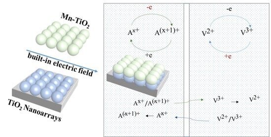
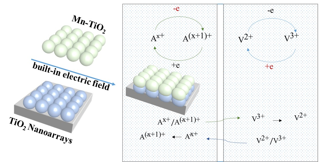
A high-performance photoanode system was developed via the concerted modulation of its structure, composition, and interfaces. A Mn-TiO2 composite phase is introduced onto the TiO2 substrate prepared by the gel spin-coating method, and directional regulation of band engineering is realized via the precise construction of a built-in electric field—significantly broadening the spectral response range (with the absorption edge red-shifted) while greatly enhancing the separation efficiency of photogenerated charge carriers.
  • Addressing the critical impact of Mn-TiO2 loading, the composite interface design is innovatively optimized to avoid the core issues of discontinuous interfaces at low loading, active site shielding, and a surge in charge transfer impedance at high loading.
  • This study focuses on the synergistic regulatory effect of annealing temperature on multiple factors. Through precise control, it achieves the controllable transformation of TiO2 crystal phases (anatase to rutile), the enhancement of Mn-TiO2 thermal stability, and the improvement of chemical bonding strength at the composite interface, thereby constructing efficient charge carrier transport channels.
  • The charge transfer barrier at the interface was mitigated by screening electrolytes with different redox potentials, thereby enhancing the compatibility between the photoanode and the electrolyte.

2. Results and Discussion

2.1. Characterization and Analysis of Photoanodes

2.1.1. Morphology and Particle Size Analysis of Photoanodes

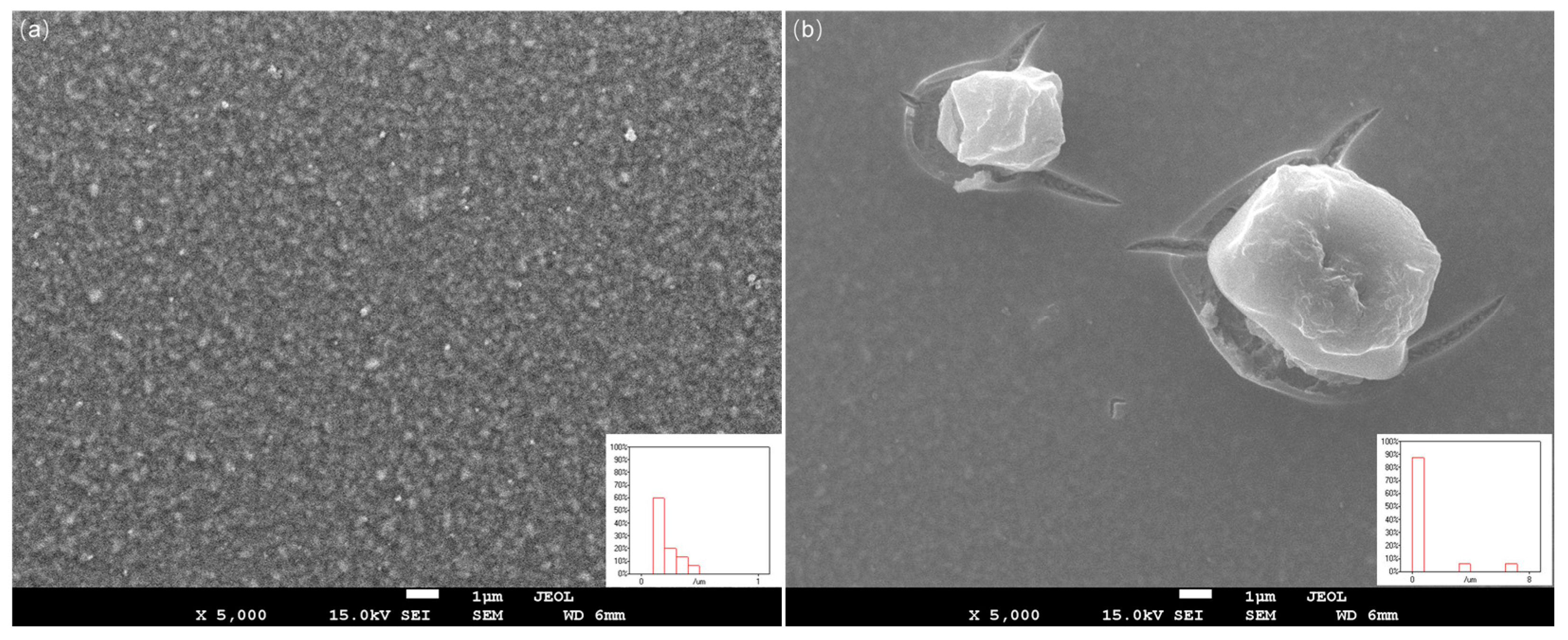
In this study, morphological analysis and elemental mapping were conducted using a JEOL JSM-IT800 field-emission SEM (JEOL Ltd., Akishima, Japan). The photoanode samples were gold-sputtered before being examined, and their elemental composition was analyzed via an integrated energy-dispersive X-ray spectroscopy (EDS) system. The comparative analysis of scanning electron microscopy (SEM) was undertaken for pure TiO2 photoanodes and Mn-TiO2/TiO2 composite photoanodes, both of which were fabricated via the spin-coating method. As illustrated in Figure 1a, a continuous and flat thin film was formed by the pristine TiO2 photoelectrode on the FTO, with no significant protrusions or pore structures detected (the average particle size is 0.21 µm). The morphological trait indicated that the precursor gel had been converted into a dense and homogeneous TiO2 layer subsequent to annealing. Such a morphology facilitates a reduction in charge transfer resistance at the electrode/electrolyte interface. However, the dense structure constrains light scattering, which give rise to inadequate light-harvesting capacity.
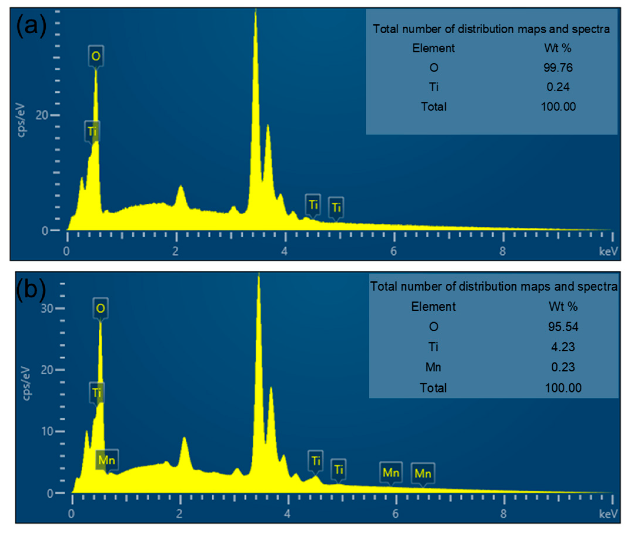
As shown by the comparative elemental analysis in Figure 2, the proportion of Mn element in Mn-TiO2/ TiO2 is 0.23%, whereas it is absent in TiO2. Subtle discrepancies are observed between the laboratory-synthesized materials and the macroscopic experimental data, which necessitate further in-depth investigation and tailored experimental procedures to reconcile these variations.

2.1.2. X-Ray Diffraction Analysis

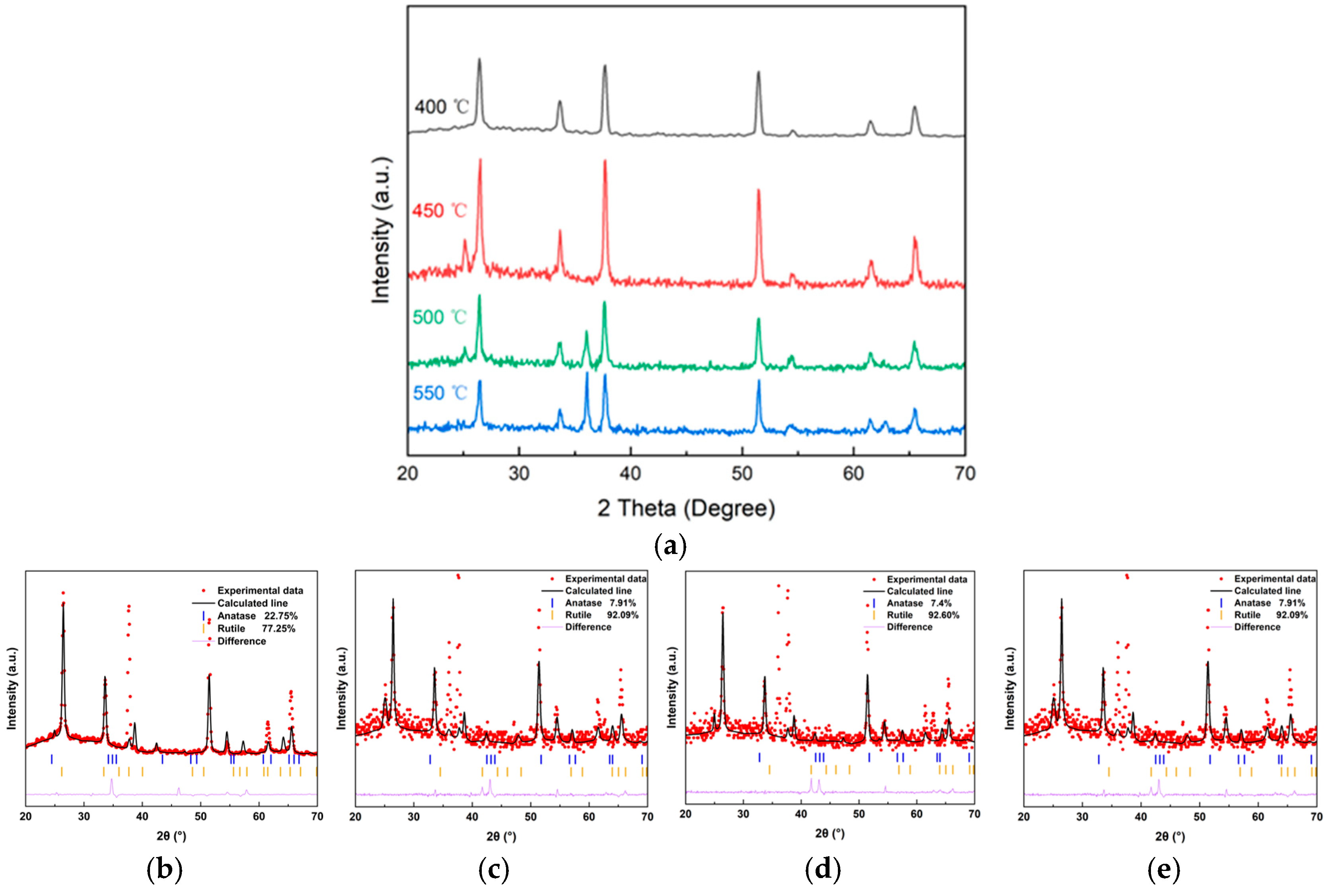
The XRD measurements were performed using Cu Kα radiation (λ = 1.5418 Å). The photoanodes with a structure of FTO/photoanode were analyzed at a scanning rate of 7°·min−1 over a 2θ range from 20° to 80°. A Bruker D8 ADVANCE diffractometer (Bruker AXS, Karlsruhe, Germany) was used for this analysis. As illustrated in Figure 3, the decisive influence of annealing temperature on the crystalline phase evolution of TiO2 is demonstrated in the X-ray diffraction (XRD) curves. For the photoanode annealed at 400 °C, only the characteristic peaks of SnO2 (e.g., 26.5° and 33.8°) originating from the FTO substrate are observed, with no diffraction peaks corresponding to TiO2 detected. The photoelectrode indicates that the insufficient temperature prevents complete crystallization of the TiO2 precursor, which remains in an amorphous or randomly aggregated state.
A distinct diffraction peak emerges at 25.2° for the photoanode annealed at 450 °C, matching the (101) crystal plane (25.355°) of anatase TiO2, as specified in the standard PDF card (PDF# 89-4921). The above confirms the successful formation of the anatase phase.
The photoanode annealed at 500 °C exhibits a phase transformation from anatase to rutile. Gradual attenuation of the anatase (101) peak at 25.2° is observed. The characteristic peaks of the rutile phase (101) (standard value 36.079°) and (002) crystal plane (standard value 62.757°) appear at 36.1° and 62.9°, respectively (PDF#75-1748). The result indicates that the rutile phase has become the main crystal phase [29]. For the photoanode annealed at 550 °C, the intensities of the peaks at 36.1° and 62.9° are significantly enhanced, with peak profiles becoming sharper. This demonstrates that the crystallinity of the rutile phase is improved and the lattice integrity is optimized. It complies with the thermodynamic principle that elevated temperatures facilitate grain growth.
A quantitative phase analysis was performed via the Rietveld refinement method using HighScore. The refinement procedure was carried out in a stepwise manner, starting with the scale factors and background, followed by the lattice parameters and profile functions, and finally the atomic coordinates when applicable [30]. The refinement converged with satisfactory goodness-of-fit indicators (e.g., Rwpb = 7.56%, Rwpc = 8.55%, Rwpd = 6.19%, Rwp1 = 4.48%). The comparative ratios of the anatase and rutile phases, derived from the Rietveld refinement of samples subjected to different temperature treatments, are presented in Figure 3b–e. With the annealing temperature sequentially increased from 400 °C, the corresponding crystallite sizes were determined to be 79 nm, 117 nm, 298 nm, and 563 nm, respectively.
Based on the XRD findings, the photoanode annealed at 500 °C is predicted to exhibit optimal photoelectrochemical performance, because the formed rutile/anatase heterophase structure enables the composite electrode to achieve a balance between light absorption and charge carrier transport. Subsequent experiments have further validated that the annealing temperature yields the best performance among the investigated conditions. Thus, 500 °C is selected as the annealing temperature for TiO2, and subsequent experiments on composite electrode fabrication are proceeded with accordingly.
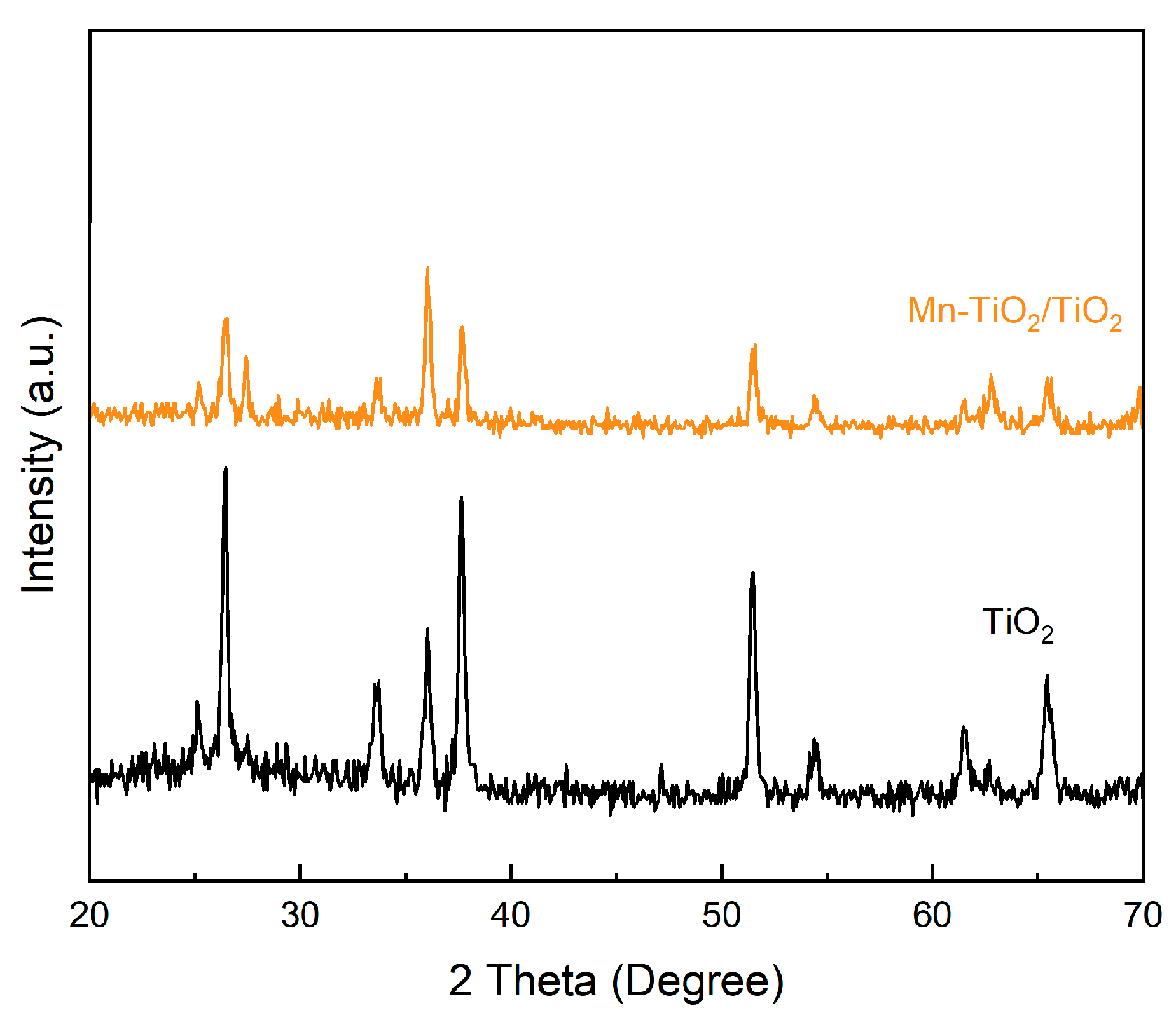
Subsequently, the comparative analysis was conducted on the XRD of pure TiO2 photoanodes and Mn-TiO2/TiO2 composite photoanodes annealed at 500 °C. As depicted in Figure 4, compared with pure TiO2 photoanodes, the Mn-TiO2/TiO2 composite photoelectrode prepared by the gel spin-coating method has a certain diffraction intensity around 27.5°. Upon composite formation with Mn-TiO2, some positions inside the lattice are occupied by Mn-TiO2 and lattice defects are introduced. As a result, the diffraction peak near 27.5° appears to be slightly broadened, alongside a concomitant reduction in peak intensity.

2.1.3. UV–Visible Testing and Analysis

The photoanodes were fabricated by spin-coating the precursor solution onto fluorine-doped tin oxide (FTO) substrates, followed by annealing. The UV–Vis absorption spectra of the resulting films were recorded using a Shimadzu UV–2600 spectrophotometer (Shimadzu Corporation, Kyoto, Japan). The optical band gap (Eg) was derived from the Tauc plot method. Briefly, the absorption data were converted to Tauc plots of (αhν)2 versus photon energy (). The band gap was obtained by extrapolating the linear region of the plot to (αhν)2 to 0.
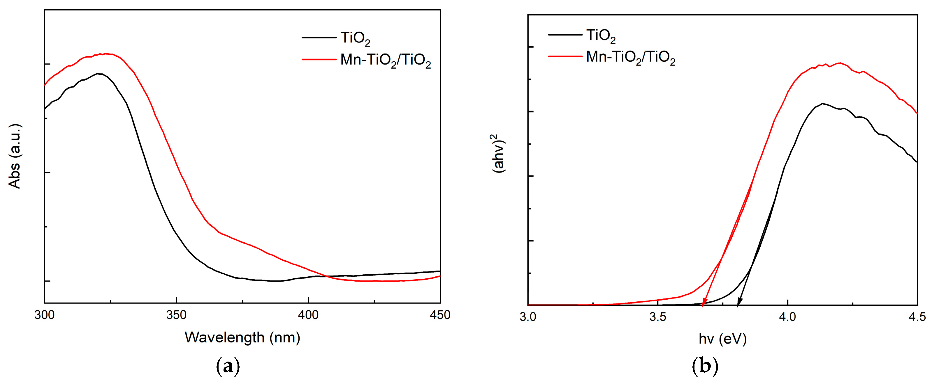
UV–visible spectroscopy was employed to investigate the optical absorption properties of TiO2 photoanode and Mn-TiO2/TiO2 composite photoanodes. As clearly illustrated in the absorption spectra (Figure 5a), compared with pure TiO2, the absorption characteristics of Mn-TiO2/TiO2 composite photoelectrode are enhanced and red-shifted. The absorption edge of pure TiO2 photoanode is situated at 385 nm (corresponding photon energy is 3.22 eV). The absorption edge of Mn-TiO2/TiO2 composite photoanode is extended to around 420 nm (2.95 eV), representing a red-shift of 35 nm.
The phenomenon originates from the narrow band gap characteristics of Mn-TiO2/TiO2 composite photoanode. The top of its valence band is higher than the valence band of TiO2, and the bottom of the conduction band is lower than the conduction band of TiO2. In Figure 5b, the energy bands are formed into a “step-like” alignment, compressing the effective band gap of the composite interface from 3.81 eV of the single component to 3.67 eV. While the optical band gap was extracted from the intercept of the linear fit in the Tauc plot ((αhν) 2 vs. ), the experimental values consistently surpassed the theoretical DFT calculations. This deviation aligns with the pervasive band gap underestimation problem in DFT, known to produce gaps that are 30–50% lower than experimental measurements [31].
The tunable bandgap of Mn-TiO2 enables spectral complementarity with TiO2 in the Mn-TiO2/TiO2 composite, thereby extending the light absorption of the electrode into the visible region. Meanwhile, the interface of Mn-TiO2 and TiO2 facilitates the formation of a built-in electric field, which enhances charge separation. Both effects are crucial for improving the solar-to-electrochemical energy conversion efficiency in SFBs.

2.1.4. Mott–Schottky Testing and Analysis

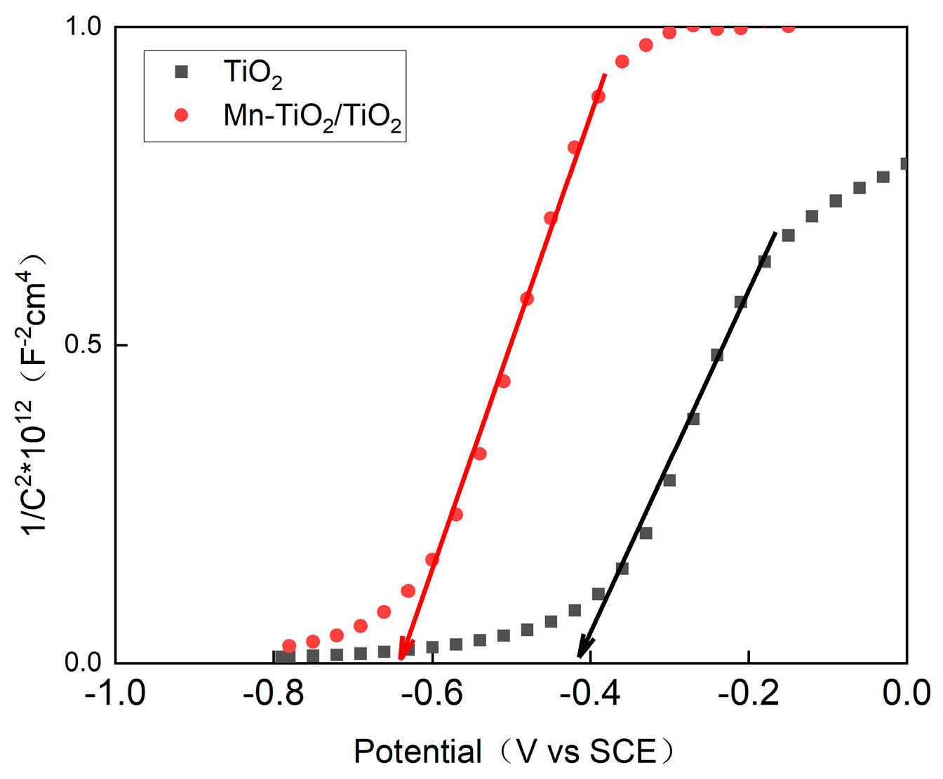
For TiO2, a built-in potential of −0.41 V was determined from Mott–Schottky measurements. The linear region of the curve was fitted, yielding a slope of 28.68, as shown in Figure 6. Based on the Mott–Schottky equation [32], the charge carrier concentration was calculated to be 5.22 × 1018 cm−3. In contrast, the built-in potential of Mn-TiO2/TiO2 is −0.64 V, the slope is 33.8, and the corresponding carrier concentration is also 5.87 × 1019 cm−3.
The composite heterostructure was constructed using a Mn-TiO2 and TiO2 configuration. An increased charge carrier concentration was achieved compared to the individual components, which is beneficial to the transmission of photogenerated carriers and the increase in reaction rate. Additionally, a negative shift in the photoanode’s built-in potential is often associated with a higher concentration of oxygen vacancy defects or other electron-accepting species. These defects or acceptors are capable of absorbing photons and facilitating electron excitation.

2.2. Half-Cell Test

2.2.1. Effect of Different Annealing Temperatures on Photoelectric Properties of TiO2 Photoelectrode

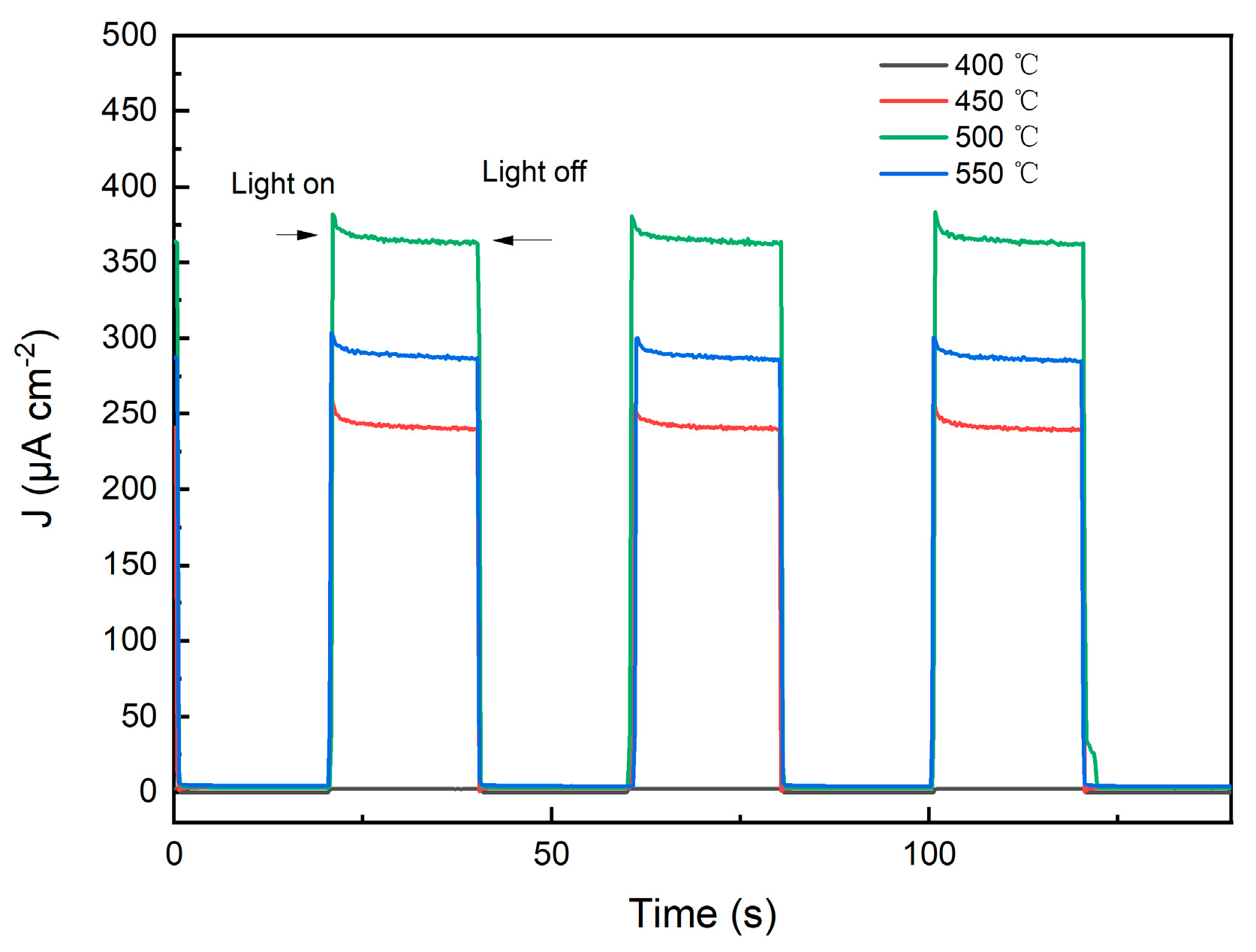
Transient photocurrent response (It) curves of TiO2 photoanode half-cells were systematically measured across different annealing temperatures to assess the photoelectrochemical performance and photoresponse characteristics of the photoanodes. As depicted in Figure 7, for the photoelectrode with an annealing temperature of 400 °C, the photocurrent density approaches zero with no discernible photoresponse plateau. This is attributed to the lack of long-range ordered lattices in the amorphous TiO2, which results in an extremely short carrier diffusion length, resulting in rapid recombination of photogenerated electron–hole pairs within the bulk.
For the photoanode annealed at 450 °C, the photocurrent density increased significantly (~0.24 mA·cm−2~0.56 V vs. SCE) with the formation of anatase crystal phase. Upon increasing the annealing temperature to 500 °C, the photocurrent density reaches a peak value of 0.36 mA·cm−2. Compared with the photoelectrode at 450 °C, the increase is 50%. The photoelectric response speed at this time is extremely rapid. It is attributed to the rutile/anatase mixed-phase junction effect, which allows the built-in electric field at the phase interface to suppress carrier recombination and increase the carrier concentration.
As the annealing temperature further increases, the photocurrent density drops back to 0.28 mA·cm−2 (22% reduction compared to the photoelectrode at 500 °C). At this time, the rutile phase is completely dominant and the advantage of the mixed-phase junction is lost. Based on the above results, the optimal annealing temperature for the TiO2 photoanodes is identified as 500 °C, which is therefore adopted as the substrate condition for subsequent experiments.

2.2.2. Performance of Mn-TiO2/TiO2 Composite Electrode

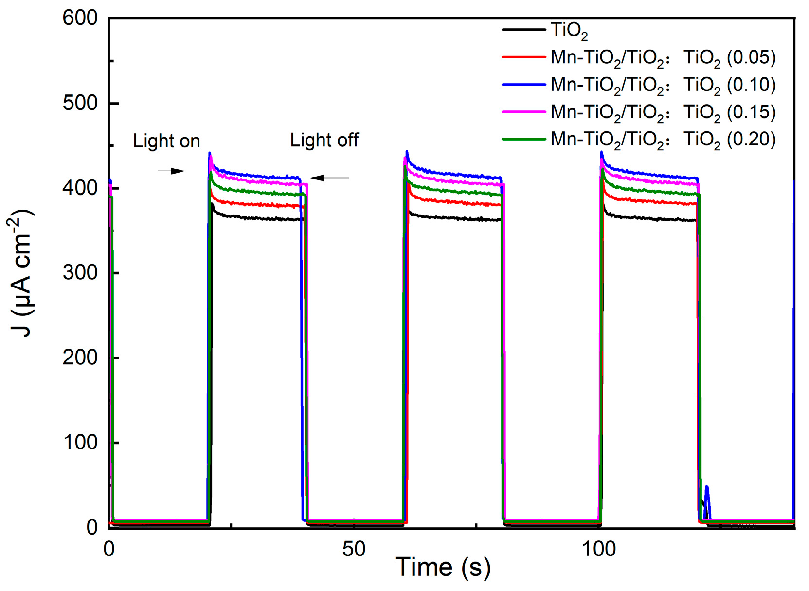
The transient photocurrent response It curve of the Mn-TiO2/TiO2 composite photoanode half-cell at varying molar ratios was systematically tested. It was used to evaluate the photoelectric properties and photoresponses of different photoelectrodes. As illustrated in Figure 8, the incorporation of Mn-TiO2 to form composite electrodes with TiO2 yielded a significant enhancement in photocurrent density. Specifically, the photocurrent densities of pure TiO2 and composite photoelectrodes (the molar ratio of Mn-TiO2 to TiO2 is 0.05, 0.10, 0.15, and 0.20) were measured as 0.36, 0.38, 0.42, 0.41, and 0.39 mA·cm−2, respectively. The improvement stems from two synergistic effects. The light absorption characteristics of the electrode are expanded through the band gap characteristics of Mn-TiO2. In addition, Mn-TiO2 and TiO2 form a mixed-phase junction to accelerate charge separation. The built-in electric field across the composite interface drives the directional transfer of photogenerated electron–hole pairs (with electrons injected from the conduction band of Mn-TiO2 to that of TiO2), suppressing recombination and enhancing charge transfer kinetics at the electrode–electrolyte interface in SFBs.
Notably, the current density of the composite photoanode reaches maximum when the molar ratio is 0.1, which is about 0.42 mA·cm−2 (~0.56 V vs. SCE). Compared with pure TiO2, the photocurrent density increased by 16.7%. For subsequent testing, the composite photoanode with a molar ratio of 0.1 was selected as the default for analysis. When the loading capacity increases to 0.15, the photocurrent density decreases as the loading capacity increases. It is attributed to excessive Mn-TiO2 causing excessive particle agglomeration or covering existing active sites on the electrode surface.
Additionally, the photocurrent density exhibits a sharp rise and fall with the on/off switching of light irradiation. It was demonstrated that the current is derived from photogenerated carriers within the photoanode. Photoanode has fast light response capability. Mn-TiO2 exhibits exceptional photochemical corrosion resistance and compatibility with electrolytes commonly employed in SFBs, thereby ensuring long-term electrode stability during charge–discharge operations.

2.3. Combination and Performance Testing of Full Battery

2.3.1. Combination of Electrolytes in the Full Battery

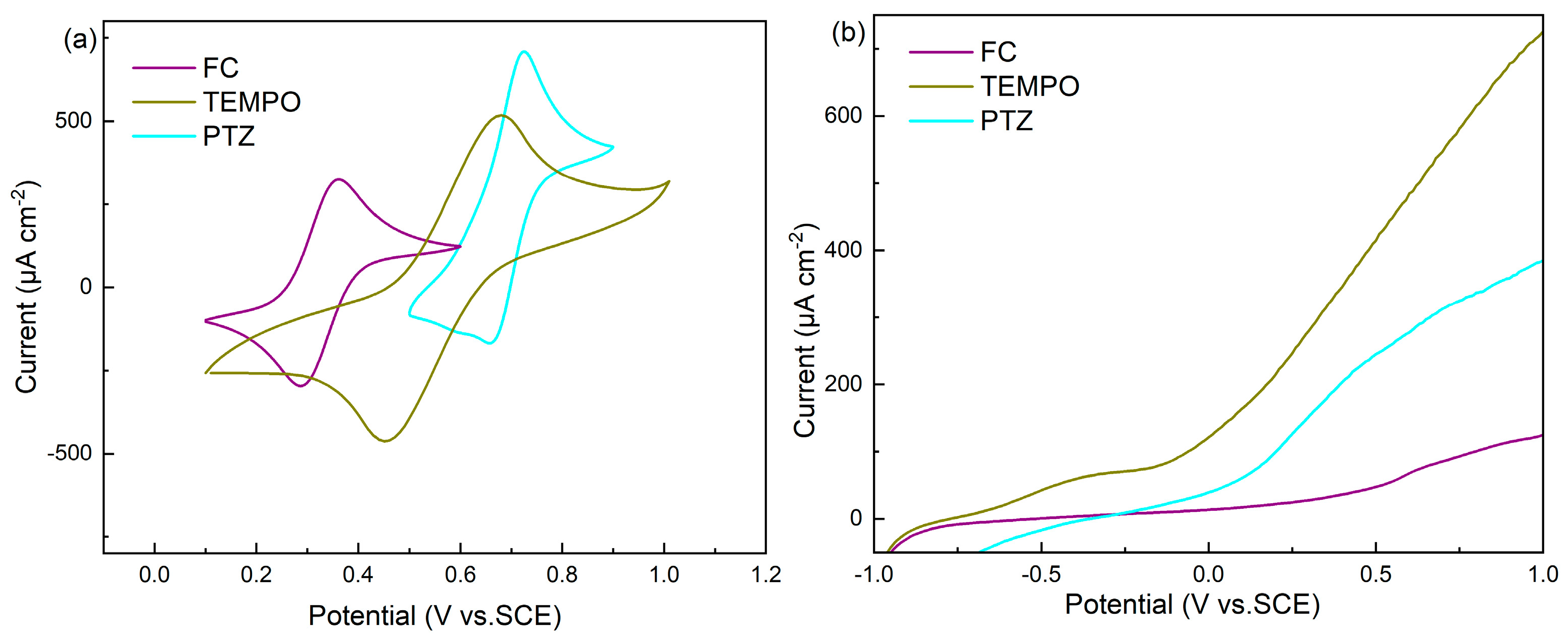
The Mn-TiO2/TiO2 composite photoanodes were paired with various electrolytes to evaluate the compatibility between photoelectrodes and electrolyte systems. Cyclic voltammetry (CV) curves and linear sweep voltammetry (LSV) curves of the different electrolytes are presented in Figure 9. As shown in Figure 9a, the redox potentials of electrolytes [ferrocene (FC), 2,2,6,6-tetramethylpiperidin-1-oxyl (TEMPO) and phenothiazine (PTZ)] were measured as 0.32 V, 0.56 V, and 0.69 V (vs. SCE), respectively. The photocurrents of the three electrolytes are illustrated in Figure 9b. The electrolyte TEMPO exhibits a significantly higher photocurrent than the other two.
There are two factors that influence the potential of the photocurrent density: thermodynamic driving force and kinetic driving force. For n-type semiconductors, the oxidizing ability of photogenerated holes is determined by the difference between the valence band maximum (EVB) of the semiconductor and the redox potential of the electrolyte (Eredox). When the Eredox is lower than the EVB, the oxidation driving force of holes at this moment is dominated by thermodynamics. The greater the difference, the stronger the driving force [33]. Theoretically, the photocurrent should increase as Eredox decreases (more negative). However, the electron energy level of the redox pair must be higher than the flat band potential to form a space charge region. The decrease in potential leads to a reduction in the depletion layer thickness, resulting in a sharp decline in charge separation efficiency [34]. The photocurrent decreases or even disappears. Consequently, TEMPO, which exhibits an intermediate redox potential, achieves the highest photoelectric conversion efficiency. It is based on TEMPO, which has both thermodynamic driving force and dynamic driving force. Moreover, the high electrochemical activity of TEMPO is also crucial.

2.3.2. Performance Test of Full Battery

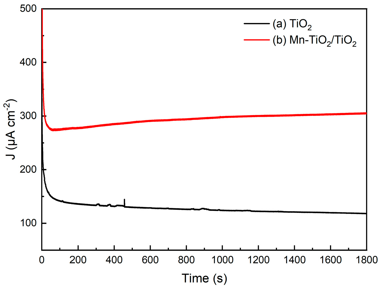
Unbiased photocharging current tests were conducted on solar flow batteries equipped with TiO2 photoanode and Mn-TiO2/TiO2 composite photoanode. As shown in Figure 10, compared with TiO2 photoanode, the photocharging current density of the Mn-TiO2/TiO2 composite photoanode has increased significantly from 120 μA·cm−2 to about 300 μA·cm−2. The photocharging current density was relatively increased by 150%. Solar-chemical energy output efficiency (ηSTC):
η STC   % = Q photoscharging / Q illumination
According to Equation (1), the calculated ηSTC is 0.12% for TiO2 and 0.31% for Mn-TiO2/TiO2. The superior photoelectrocatalytic activity of the composite photoanode facilitates the conversion of solar energy to electrical energy in the integrated solar flow battery. The photocharging performance of the battery remains stable in the short term (0.5 h). Although the photocharging current (460 μA) and STC (0.35%) in a recent report are slightly higher than this work [35], the difference can be attributed to our use of a deep eutectic solvent (DES) as the electrolyte. The deep eutectic solvent was employed in this work. Its higher viscosity (compared to water) does limit mass transfer and photocurrent, but it offers a critically wider electrochemical potential window, creating a better platform for testing diverse electrolyte/photoanode combinations. Moreover, we have adopted a simpler photoanode fabrication method, avoiding the need for the complex, precision-dependent Fe2O3/CuxO heterojunction structure used in the reference work, which necessitates an ultrathin CuxO coating to compensate for the short hole diffusion length of Fe2O3.

3. Materials and Methods

3.1. Preparation of TiO2 Gel Photoelectrode

With tetrabutyl titanate (99.0%, Aladdin, Shanghai, China) serving as the precursor, the sol–gel preparation of TiO2 gel was carried out via the following procedure. Initially, 5 mL of tetrabutyl titanate was dispersed in 1 mL of anhydrous ethanol (AR grade, Sinopharm, Shanghai, China), to which 1.5 mL of acetylacetone (AR, Aladdin, Shanghai, China) was then added as a stabilizer, and the resultant mixture was subjected to stirring for 30 min. A mixed solution comprising 10 mL of anhydrous ethanol and 2 mL of deionized water was subsequently introduced into the system, and after 5 min of agitation, concentrated hydrochloric acid (36~38%, Sinopharm, Shanghai, China) was added dropwise to adjust the pH of the mixture to 3. Following a further 10 min stirring period, 0.69 g of polyethylene glycol (Aladdin, Shanghai, China), acting as a surface modifier, was incorporated into the solution, which was then stirred for an additional minute. The mixture was finally allowed to stand for aging over 24 h, yielding the target TiO2 gel in Figure 11.
The fabrication of TiO2 gel photoelectrodes was implemented in accordance with the following procedure. First, fluorine-doped tin oxide (FTO) glass substrates were subjected to thorough cleaning and subsequent drying. A 30 μL aliquot of the as-synthesized TiO2 sol was then deposited onto 1 cm × 1 cm FTO substrates, which were first spin-coated at a low rotational speed of 1000 rpm for 5 s and then at a high rotational speed of 3000 rpm for a further 20 s. The coated substrates were placed on a hotplate and dried at 80 °C for 5 min to form a thin film, and this spin-coating and drying cycle was repeated to fabricate a monolayer of TiO2 film. Repeating the spin-coating step, a total of five layers of TiO2 thin film were thereby prepared. Finally, the prepared samples were transferred into a muffle furnace (KSL-1100X, Hefei Kejing, Hefei, China) and annealed for 2 h. To elucidate the influence of annealing temperature on electrode properties, the annealing process was conducted at three distinct temperatures, namely, 450 °C, 500 °C, and 550 °C.

3.2. Preparation of Mn-TiO2/TiO2 Composite Photoelectrode

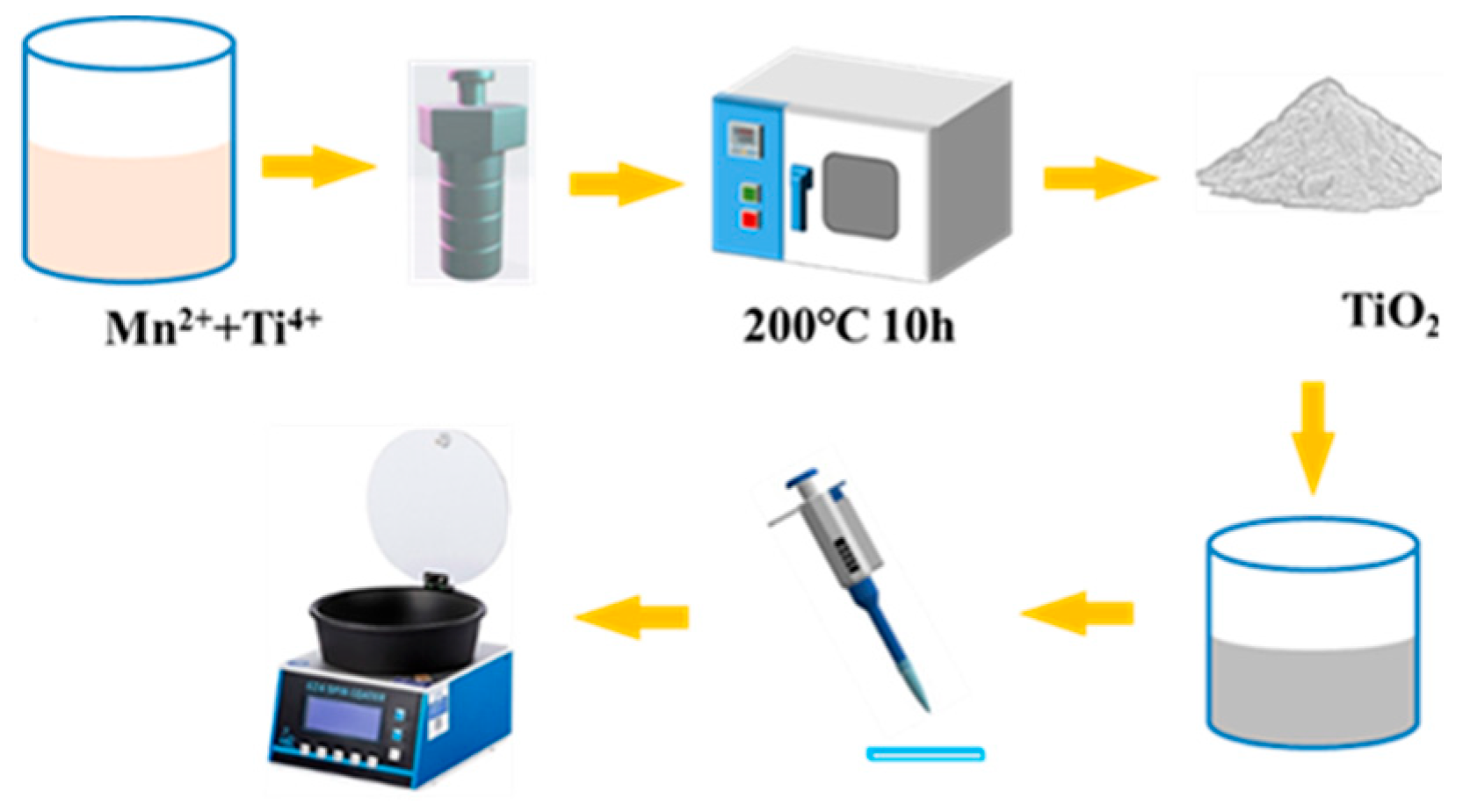
20 mL of glacial acetic acid (99.5%, Sinopharm, China) and 30 mL of N, N-dimethylformamide (99.8%, Aladdin, China) were first mixed thoroughly with manganese acetate (99.0%, Aladdin, China) under magnetic agitation for 30 min. A total of 2.5 mL of tetrabutyl titanate (99.0%, Aladdin, Shanghai, China) (with a molar ratio of Ti to Mn atoms fixed at 1:3) was added dropwise to the mixture, followed by another 30 min of magnetic agitation [36]. The resulting yellow transparent solution was transferred to high pressure reactor, which was then placed in a blast drying oven and heated isothermally at 200 °C for 10 h. After complete cooling, the white precipitate was collected and subjected to centrifugation twice with deionized water. The centrifuged precipitate was dried isothermally at 60 °C for 24 h and ground to obtain the precursor sample in Figure 12. The as-prepared sample was dissolved in anhydrous ethanol, and Mn-TiO2 was spin-coated onto the substrate prepared in Section 3.1. A series of Mn-TiO2/TiO2 composite photocatalytic electrodes were fabricated with molar ratios (Mn-TiO2:TiO2 = 0:1, 0.05:1, 0.1:1, 0.15:1, and 0.2:1). All the electrode samples were annealed in a muffle furnace at 500 °C for 2 h to finalize the synthetic procedure.

3.3. Preparation of Electrolyte

Deep eutectic solvent (DES) composed of choline chloride (AR, Aladdin, Shanghai, China) and ethylene glycol (AR, Sinopharm, Shanghai, China) at a molar ratio of 1:2 was utilized as the electrolyte solvent. Ferrocene (FC) (96.0%, Aladdin, Shanghai, China), 2,2,6,6-tetramethylpiperidine-1-oxyl (TEMPO) (95.0%, Aladdin, Shanghai, China), and phenothiazine (PTZ) (98.0%, Aladdin, Shanghai, China) were designated as the active species for the positive electrolyte. Vanadium (III) chloride (VCl3) was selected as the negative electrolyte with a concentration of 0.01 mol·L−1. Linear sweep voltammetry (LSV) tests were then performed to characterize the electrochemical performance of the assembled electrolyte system.

3.4. Battery Test

The photoelectrochemical performance of the photoanodes was assessed using an Ivium electrochemical workstationVERTEX.C, Netherlands (Ivium Technologies B.V., Eindhoven, The Netherlands). Photoelectrode performance was derived from half-cell test results, which were carried out in a standard three-electrode configuration. The photoanode was deployed as the working electrode and immersed in the 0.1 mol·L−1 electrolyte. Platinum electrode was designated as the counter electrode, and a saturated calomel electrode (SCE) was utilized as the reference electrode. (a) The electrochemical workstation was configured for Mott–Schottky analysis using the following parameters: a DC potential sweep is applied from 0 V to −1.0 V (vs. SCE), while superimposing a 1000 Hz AC signal with a 10 mV amplitude. (b) The solar simulator was equipped with an AM 1.5G filter for testing. The incident light power density was calibrated to 100 mW·cm−2 using an optical power meter referenced to a silicon photodetector. The photocurrent transient was measured in potentiostatic mode with a sampling interval of 0.2 s under periodic illumination. It curves were recorded under alternating dark and illuminated conditions during on–off illumination cycles at zero applied bias. Transient current scanning and other analytical methods were applied to characterize the physicochemical and electrochemical properties of the as-fabricated electrodes under specific electrolyte conditions.
Furthermore, the electrolyte was subjected to testing to quantify its electrochemical activity and redox potential using an electrochemical workstation (CHI 604, CH Instruments, Shanghai, China). Cyclic voltammetry and linear sweep voltammetry were performed at a scan rate of 10 mV·s−1. The scan ranges, determined by the respective redox potentials, were 0.1 to 0.6 V for the FC electrolyte, 0.1 to 1.0 V for the TEMPO electrolyte, and 0.5 to 0.9 V for the PTZ electrolyte. Linear sweep voltammetry was performed over a range of −1.0 to 1.0 V.
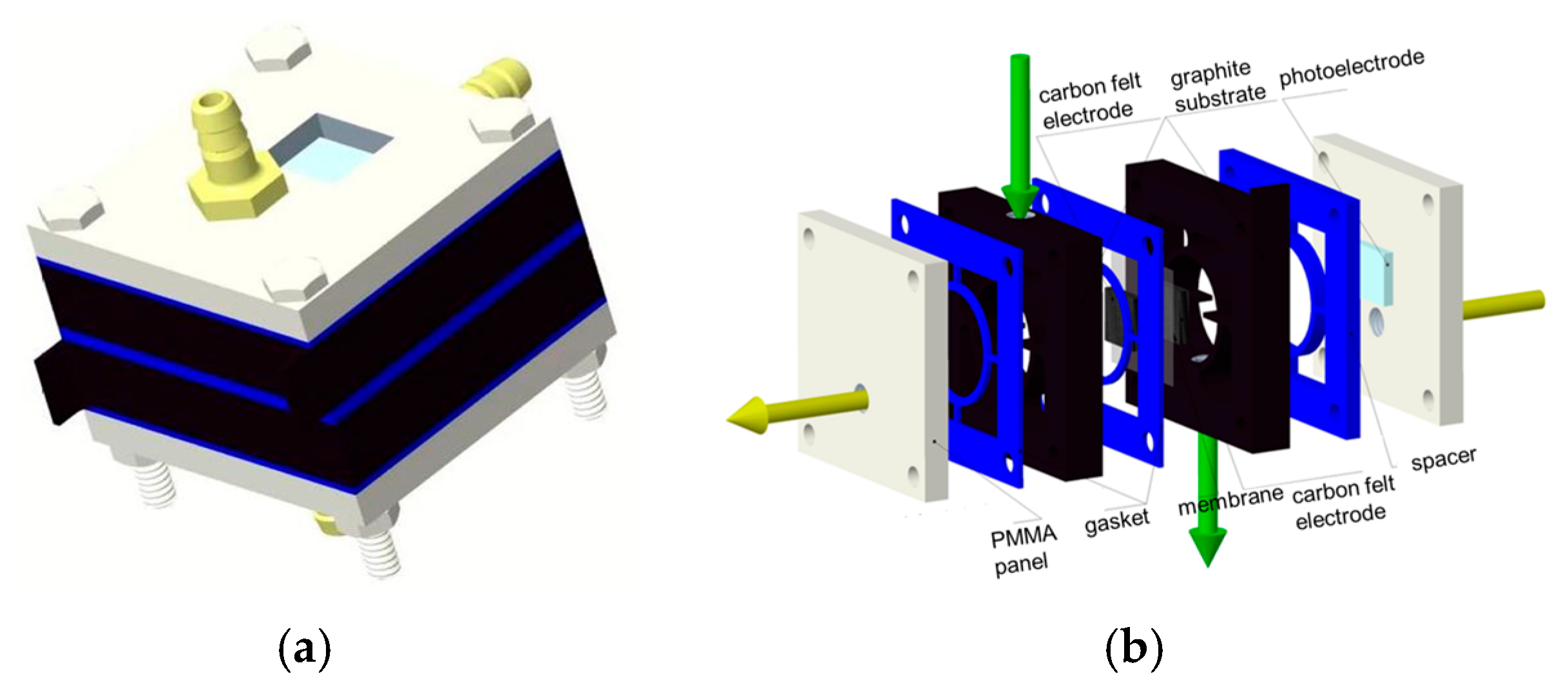
The Mn-TiO2/TiO2 composite photoanode and TiO2 photoanode were paired with a 0.01 mol·L−1 TEMPO/VCl3 electrolyte. The photoanode was sandwiched between current collectors, with graphite felt positioned atop the anode-side collector. The photoanode and the anode graphite felt were arranged in a staggered configuration. A Nafion 212 membrane (Chemours, Wilmington, DE, USA) was then placed, followed by the cathode graphite felt, the cathode current collector, and finally an organic glass plate. All components were carefully aligned in parallel and firmly assembled into an integrated solar flow battery using four securing studs, as illustrated in Figure 13. The solar irradiance was set at 100 mW/cm2. The solar redox flow battery systems were subjected to photocharging performance tests under zero external bias.

4. Conclusions

In conclusion, a high-performance solar flow battery was established through the multi-dimensional regulation of “structure–composition–interface”.
  • The Mn-TiO2 composite phase was introduced into the TiO2 substrate via the gel spin-coating method. The precise construction of the built-in electric field significantly broadens the spectral response range (evidenced by 35 nm red-shift in the light absorption edge), while substantially enhancing the separation efficiency of photocharge carriers.
  • Addressing the critical impact of TiO2 loading, the composite interface between Mn-TiO2 and TiO2 is optimized. The interface discontinuity at low load and the surge of charge transfer impedance at high load are avoided.
  • The annealing temperature has synergistic regulatory effects on multiple factors. The controllable transformation of the TiO2 crystal phase was achieved, alongside enhanced thermal stability of TiO2. In addition, the chemical bond strength of the composite interface between Mn-TiO2 and TiO2 has also been improved, thereby constructing an efficient carrier transport pathway.
  • Based on the charge transfer mechanism at the photoelectrode/electrolyte interface, the charge transfer barrier at this interface is directionally adjusted by screening catholytes with distinct redox potentials. The photocharging current density was relatively increased by 150%.
Moving forward, key objectives are to elevate the photocharging current density to the mA·cm−2 level and the efficiency beyond 1%. Subsequently, demonstrating long-term stability will be the crucial next step toward practical application.

Author Contributions

Conceptualization, P.L. and Q.X.; methodology, P.L. and Y.X.; validation, P.L.; formal analysis, P.L. and Q.X.; data curation, P.L.; writing—original draft preparation, P.L.; writing—review and editing, Y.X., X.Z., W.L. and Q.X. All authors have read and agreed to the published version of the manuscript.

Funding

This research was funded by start-up funding for scientific research for high-level talents.

Data Availability Statement

Data are contained within this article.

Conflicts of Interest

The authors declare no conflicts of interest.

References

  1. Alotto, P.; Guarnieri, M.; Moro, F. Redox flow batteries for the storage of renewable energy: A review. Renew. Sustain. Energy Rev. 2014, 29, 325–335. [Google Scholar] [CrossRef] [Scilit]
  2. Ye, J.; Xia, L.; Li, H.; de Arquer, F.P.G.; Wang, H. The Critical Analysis of Membranes toward Sustainable and Efficient Vanadium Redox Flow Batteries. Adv. Mater. 2024, 36, 2402090. [Google Scholar] [CrossRef] [Scilit]
  3. Wang, W.; Luo, Q.; Li, B.; Wei, X.; Li, L.; Yang, Z. Recent Progress in Redox Flow Battery Research and Development. Adv. Funct. Mater. 2013, 23, 970–986. [Google Scholar] [CrossRef] [Scilit]
  4. Li, W.; Jin, S. Design Principles and Developments of Integrated Solar Flow Batteries. Acc. Chem. Res. 2020, 53, 2611–2621. [Google Scholar] [CrossRef] [Scilit] [PubMed]
  5. Yu, M.; McCulloch, W.D.; Beauchamp, D.R.; Huang, Z.; Ren, X.; Wu, Y. Aqueous Lithium–Iodine Solar Flow Battery for the Simultaneous Conversion and Storage of Solar Energy. J. Am. Chem. Soc. 2015, 137, 8332–8335. [Google Scholar] [CrossRef] [Scilit]
  6. Li, W.; Zheng, J.; Hu, B.; Fu, H.-C.; Hu, M.; Veyssal, A.; Zhao, Y.; He, J.-H.; Liu, T.L.; Ho-Baillie, A.; et al. High-performance solar flow battery powered by a perovskite/silicon tandem solar cell. Nat. Mater. 2020, 19, 1326–1331. [Google Scholar] [CrossRef] [Scilit] [PubMed]
  7. Nielander, A.C.; Shaner, M.R.; Papadantonakis, K.M.; Francis, S.A.; Lewis, N.S. A taxonomy for solar fuels generators. Energy Environ. Sci. 2015, 8, 16–25. [Google Scholar] [CrossRef] [Scilit]
  8. Li, J.; Lin, Y.; Chen, R.; Zhu, X.; Ye, D.; Yang, Y.; Yu, Y.; Wang, D.; Liao, Q. Solar energy storage by a microfluidic all-vanadium photoelectrochemical flow cell with self-doped TiO2 photoanode. J. Energy Storage 2021, 43, 103228. [Google Scholar] [CrossRef] [Scilit]
  9. Yan, N.F.; Li, G.R.; Gao, X.P. Electroactive Organic Compounds as Anode-Active Materials for Solar Rechargeable Redox Flow Battery in Dual-Phase Electrolytes. J. Electrochem. Soc. 2014, 161, A736. [Google Scholar] [CrossRef] [Scilit]
  10. Zhao, W.; Wang, X.-F.; Zheng, E.; Wei, Y.; Sanehira, Y.; Chen, G. High capacity WO3 film as efficient charge collection electrode for solar rechargeable batteries. J. Power Sources 2017, 350, 28–34. [Google Scholar] [CrossRef] [Scilit]
  11. Urbain, F.; Murcia-López, S.; Nembhard, N.; Vázquez-Galván, J.; Flox, C.; Smirnov, V.; Welter, K.; Andreu, T.; Finger, F.; Morante, J.R. Solar vanadium redox-flow battery powered by thin-film silicon photovoltaics for efficient photoelectrochemical energy storage. J. Phys. D Appl. Phys. 2018, 52, 044001. [Google Scholar] [CrossRef] [Scilit]
  12. Li, W.; Kerr, E.; Goulet, M.-A.; Fu, H.-C.; Zhao, Y.; Yang, Y.; Veyssal, A.; He, J.-H.; Gordon, R.G.; Aziz, M.J.; et al. A Long Lifetime Aqueous Organic Solar Flow Battery. Adv. Energy Mater. 2019, 9, 1900918. [Google Scholar] [CrossRef] [Scilit]
  13. Ribao, P.; Corredor, J.; Rivero, M.J.; Ortiz, I. Role of reactive oxygen species on the activity of noble metal-doped TiO2 photocatalysts. J. Hazard. Mater. 2019, 372, 45–51. [Google Scholar] [CrossRef] [Scilit]
  14. Rivero, M.J.; Ribao, P.; Gomez-Ruiz, B.; Urtiaga, A.; Ortiz, I. Comparative performance of TiO2-rGO photocatalyst in the degradation of dichloroacetic and perfluorooctanoic acids. Sep. Purif. Technol. 2020, 240, 116637. [Google Scholar] [CrossRef] [Scilit]
  15. Feng, H.; Jiao, X.; Chen, R.; Zhu, X.; Liao, Q.; Ye, D.; Zhang, B.; Zhang, W. A microfluidic all-vanadium photoelectrochemical cell with the N-doped TiO2 photoanode for enhancing the solar energy storage. J. Power Sources 2019, 419, 162–170. [Google Scholar] [CrossRef] [Scilit]
  16. Wei, Z.; Shen, Y.; Liu, D.; Hsu, C.; Sajjad, S.D.; Rajeshwar, K.; Liu, F. Geometry-enhanced ultra-long TiO2 nanobelts in an all-vanadium photoelectrochemical cell for efficient storage of solar energy. Nano Energy 2016, 26, 200–207. [Google Scholar] [CrossRef] [Scilit]
  17. Tian, G.; Jervis, R.; Briscoe, J.; Titirici, M.; Jorge Sobrido, A. Efficient harvesting and storage of solar energy of an all-vanadium solar redox flow battery with a MoS2@TiO2 photoelectrode. J. Mater. Chem. A 2022, 10, 10484–10492. [Google Scholar] [CrossRef] [Scilit]
  18. Ma, J.; Pan, Z.; Tagliabue, G. High-Performance Hematite Photoanodes for Unassisted Recharging of Solar Redox Flow Battery. Sol. RRL 2024, 8, 2400477. [Google Scholar] [CrossRef] [Scilit]
  19. Tichter, T.; Naumann, K.; Vesborg, P.C.K. Photoelectrochemical, all-soluble iron redox-flow battery for the direct conversion of solar energy. Electrochim. Acta 2024, 487, 144140. [Google Scholar] [CrossRef] [Scilit]
  20. Gu, Z.; Lu, P.; Zhang, Z.; Ma, Q.; Bu, Y.; Su, H.; Wei, L.; Yang, W.; Xu, Q. Effectively enhancing the performance of solar flow battery via constructing TiO2-g-C3N4 heterojunction photoanode. J. Power Sources 2025, 640, 236696. [Google Scholar] [CrossRef] [Scilit]
  21. Zhou, W.; Liu, M.; Cao, Y.; Sun, Y.; Chang, Q.; Zhao, X.; Wang, H.; Liu, S.; Shi, J.; Li, C. Breaking the photoelectrochemical activity-battery voltage trade-off for efficient photocharging of TEMPO/quinone redox flow battery. Chem. Eng. J. 2025, 507, 160162. [Google Scholar] [CrossRef] [Scilit]
  22. Geysens, P.; Evers, J.; Dehaen, W.; Fransaer, J.; Binnemans, K. Enhancing the solubility of 1,4-diaminoanthraquinones in electrolytes for organic redox flow batteries through molecular modification. RSC Adv. 2020, 10, 39601–39610. [Google Scholar] [CrossRef] [Scilit]
  23. Lee, W.; Kwon, B.W.; Kwon, Y. Effect of Carboxylic Acid-Doped Carbon Nanotube Catalyst on the Performance of Aqueous Organic Redox Flow Battery Using the Modified Alloxazine and Ferrocyanide Redox Couple. ACS Appl. Mater. Interfaces 2018, 10, 36882–36891. [Google Scholar] [CrossRef] [Scilit] [PubMed]
  24. Li, W.; Fu, H.-C.; Zhao, Y.; He, J.-H.; Jin, S. 14.1% Efficient Monolithically Integrated Solar Flow Battery. Chem 2018, 4, 2644–2657. [Google Scholar] [CrossRef] [Scilit]
  25. Wei, Z.; Almakrami, H.; Lin, G.; Agar, E.; Liu, F. An organic-inorganic hybrid photoelectrochemical storage cell for improved solar energy storage. Electrochim. Acta 2018, 263, 570–575. [Google Scholar] [CrossRef] [Scilit]
  26. Lu, P.; Gu, Z.; Zhang, Z.; Lu, M.; Ma, Q.; Su, H.; Xu, Q. Study on performance enhancement of electro-fueled solar flow battery system by nickel-doped titanium dioxide photoanode. Energy Convers. Manag. 2024, 301, 117997. [Google Scholar] [CrossRef] [Scilit]
  27. Liao, S.; Zong, X.; Seger, B.; Pedersen, T.; Yao, T.; Ding, C.; Shi, J.; Chen, J.; Li, C. Integrating a dual-silicon photoelectrochemical cell into a redox flow battery for unassisted photocharging. Nat. Commun. 2016, 7, 11474. [Google Scholar] [CrossRef] [Scilit]
  28. Wedege, K.; Azevedo, J.; Khataee, A.; Bentien, A.; Mendes, A. Direct Solar Charging of an Organic–Inorganic, Stable, and Aqueous Alkaline Redox Flow Battery with a Hematite Photoanode. Angew. Chem. Int. Ed. 2016, 55, 7142–7147. [Google Scholar] [CrossRef] [Scilit]
  29. Lazzeri, M.; Vittadini, A.; Selloni, A. Structure and energetics of stoichiometric TiO2 anatase surfaces. Phys. Rev. B 2001, 63, 155409. [Google Scholar] [CrossRef] [Scilit]
  30. Fauzi, A.; Lalasari, L.H.; Sofyan, N.; Ferdiansyah, A.; Dhaneswara, D.; Yuwono, A.H. Study of TiO2 nanotube crystal structure by rietveld analysis. AIP Conf. Proc. 2023, 2538, 020007. [Google Scholar] [CrossRef] [Scilit]
  31. Li, X.; Kang, B.; Dong, F.; Zhang, Z.; Luo, X.; Han, L.; Huang, J.; Feng, Z.; Chen, Z.; Xu, J.; et al. Enhanced photocatalytic degradation and H2/H2O2 production performance of S-pCN/WO2.72 S-scheme heterojunction with appropriate surface oxygen vacancies. Nano Energy 2021, 81, 105671. [Google Scholar] [CrossRef] [Scilit]
  32. Li, L.; Nan, B.; Xu, N.N.; Bai, G.; He, R.; Liu, Y.; Qiao, J. Sunlight-promoted CO2 electroreduction with staggered p-n heterojunction by indium-doped bismuth 3D nanoflower structure on oxidized copper foam as self-standing photoelectric cathode over a wide potential window. Appl. Catal. B Environ. Energy 2025, 360, 124489. [Google Scholar] [CrossRef] [Scilit]
  33. Jing, J.; Yang, J.; Li, W.; Wu, Z.; Zhu, Y. Construction of Interfacial Electric Field via Dual-Porphyrin Heterostructure Boosting Photocatalytic Hydrogen Evolution. Adv. Mater. 2022, 34, 2106807. [Google Scholar] [CrossRef] [Scilit] [PubMed]
  34. Chen, R.; Zhang, D.; Wang, Z.; Li, D.; Zhang, L.; Wang, X.; Fan, F.; Li, C. Linking the Photoinduced Surface Potential Difference to Interfacial Charge Transfer in Photoelectrocatalytic Water Oxidation. J. Am. Chem. Soc. 2023, 145, 4667–4674. [Google Scholar] [CrossRef] [Scilit] [PubMed]
  35. Ma, J.; Sabzehparvar, M.; Pan, Z.; Tagliabue, G. Nanostructured Fe2O3/CuxO heterojunction for enhanced solar redox flow battery performance. J. Mater. Chem. A 2025, 13, 1320–1329. [Google Scholar] [CrossRef] [Scilit]
  36. Lu, P.; Gu, Z.; Zhang, Z.; Su, H.; Ma, Q.; Li, C.; Wei, L.; Xu, Q. Outside-to-inside: Efficacy comparation of Mn bulk and surface-doped TiO2{201} in E-fueled solar flow battery system. Surf. Interfaces 2024, 46, 104174. [Google Scholar] [CrossRef] [Scilit]
Figure 1. SEM and size distribution of photoelectrodes (a) TiO2 and (b) Mn-TiO2/TiO2.
Catalysts 16 00112 g001
Figure 2. Total number of distribution maps and spectra of photoelectrodes (a) TiO2 and (b) Mn-TiO2/TiO2.
Catalysts 16 00112 g002
Figure 3. (a) XRD of TiO2 photoelectrode at different annealing temperatures; Rietveld analysis for (b) 400 °C, (c) 450 °C, (d) 500 °C, and (e) 550 °C.
Catalysts 16 00112 g003
Figure 4. XRD of TiO2 and Mn-TiO2/TiO2 photoelectrode at 500 °C.
Catalysts 16 00112 g004
Figure 5. (a) UV–visible absorption spectra and (b) Tauc plot of TiO2 and Mn-TiO2/TiO2 photoelectrode.
Catalysts 16 00112 g005
Figure 6. Mott–Schottky curve of photoelectrodes TiO2 and Mn-TiO2/TiO2.
Catalysts 16 00112 g006
Figure 7. It curves of TiO2 photoanode half-cells.
Catalysts 16 00112 g007
Figure 8. It curve of Mn-TiO2/TiO2 composite photoanode half-cell at varying molar ratios.
Catalysts 16 00112 g008
Figure 9. (a) CV and (b) LSV curves of electrolytes.
Catalysts 16 00112 g009
Figure 10. Photocharging current density of solar flow batteries with (a) TiO2 and (b) Mn-TiO2/TiO2 photoanode.
Catalysts 16 00112 g010
Figure 11. Preparation method of TiO2 gel photoanode.
Catalysts 16 00112 g011
Figure 12. Preparation process of Mn-TiO2.
Catalysts 16 00112 g012
Figure 13. Integrated solar flow battery (a) assembly drawing; (b) exploded view.
Catalysts 16 00112 g013
Table 1. Photoelectrode and electrolyte of solar redox flow batteries in recent years.
PhotoelectrodeElectrolyteSolar-to-Output
Electricity Efficiency
Year
MoS2@TiO2V3+/VO2+0.52%2022 [17]
nanoporous
α-Fe2O3
Na4Fe(CN)6-AQDS 0.23%2023 [18]
Ge/GaAs/GaInP triple-junctionferro/ferricyanide
iron–triethanolamine
/
cycle life (120 h)
2024 [19]
TiO2-g-C3N4TEMPO/VCl30.59%2025 [20]
carbon-modified a-SiTEMPO/quinone5.4%2025 [21]
Disclaimer/Publisher’s Note: The statements, opinions and data contained in all publications are solely those of the individual author(s) and contributor(s) and not of MDPI and/or the editor(s). MDPI and/or the editor(s) disclaim responsibility for any injury to people or property resulting from any ideas, methods, instructions or products referred to in the content.