Abstract
Constructing heterojunction photocatalysts with efficient interfacial charge transfer is critical for solar-driven hydrogen evolution. In this study, a highly dispersed MoS2/g-C3N4 composite was successfully synthesized via a stirring-assisted hydrothermal in situ growth strategy. The introduction of stirring during synthesis significantly enhanced the uniform dispersion of MoS2 nanosheets and exposed abundant edge sites, leading to well-integrated heterojunctions with enhanced interfacial contact. Comprehensive structural and photoelectronic characterizations (XRD, SEM, TEM, EDS mapping, UV–Vis, TRPL, EIS, EPR) confirmed that the composite exhibited improved visible-light absorption, accelerated charge separation, and suppressed recombination. Under simulated solar irradiation with triethanolamine (TEOA) as a sacrificial agent, the optimized 24% MoS2/g-C3N4-S catalyst achieved a high hydrogen evolution rate of 14.33 mmol·g−1·h−1 at a catalyst loading of 3.2 mg, significantly outperforming the unstirred and pristine components, and demonstrating excellent cycling stability. Mechanistic studies revealed that the performance enhancement is attributed to the synergistic effects of Type-II heterojunction formation and edge-site-rich MoS2 co-catalysis. This work provides a scalable approach for non-noble metal interface engineering and offers insight into the design of efficient and durable photocatalysts for solar hydrogen production.
1. Introduction
The escalating global energy crisis and environmental degradation have intensified the pursuit of clean and sustainable energy solutions. Hydrogen energy, characterized by its high energy density, zero carbon emissions, and renewability, stands out as a promising alternative. Among various hydrogen production methods, photocatalytic water splitting using semiconductor materials offers a green and efficient pathway, directly harnessing solar energy to convert water into hydrogen [1]. However, the practical application of this technology is hindered by challenges such as limited visible light absorption, low quantum efficiency, and poor stability of existing photocatalysts [2].
Graphitic carbon nitride (g-C3N4), a metal-free semiconductor, has garnered significant attention due to its suitable bandgap (~2.7 eV), excellent chemical stability, abundant raw materials, and facile synthesis [3]. These attributes make it a compelling candidate for applications in photocatalytic water splitting, CO2 reduction, and pollutant degradation. The conduction band position of g-C3N4 (~−1.1 eV) endows it with strong reducing power, sufficient for driving the hydrogen evolution reaction (HER). Nevertheless, its photocatalytic performance is limited by rapid recombination of photogenerated electron-hole pairs, low specific surface area, and inadequate visible light absorption. To overcome these limitations, strategies such as heterojunction construction, heteroatom doping, and cocatalyst loading have been explored to enhance its photocatalytic efficiency.
Transition metal dichalcogenides (TMDs), particularly molybdenum disulfide (MoS2), have emerged as effective cocatalysts in photocatalytic systems due to their unique electronic properties and layered structures. MoS2 exhibits a sandwich-like S–Mo–S layered configuration, where the basal planes are catalytically inert, but the edge sites demonstrate remarkable HER activity. Density functional theory (DFT) calculations reveal that the Gibbs free energy for hydrogen adsorption at MoS2 edge sites is close to zero, indicating high catalytic activity comparable to that of platinum [4,5,6]. Additionally, the conduction band position of MoS2 (~−0.1 eV) facilitates the acceptance of electrons from photoexcited semiconductors like g-C3N4, promoting efficient charge separation and transfer.
Integrating MoS2 with g-C3N4 to form heterojunctions not only provides additional active sites but also enhances the separation of photogenerated charge carriers. Studies have demonstrated that MoS2/g-C3N4 composites exhibit superior photocatalytic performance compared to their individual components [7,8,9,10,11], attributed to the effective spatial separation of electrons and holes. In these systems, electrons generated in g-C3N4 under light irradiation can transfer to MoS2, where they participate in the HER, while holes remain in g-C3N4 to drive oxidation reactions. Moreover, the incorporation of MoS2 can improve the light absorption properties of g-C3N4 and create internal electric fields at the interface, further facilitating charge separation.
Despite the potential of MoS2/g-C3N4 heterojunctions, their photocatalytic efficiency is highly dependent on the quality of the interface and the dispersion of MoS2. Conventional synthesis methods, such as physical mixing in solutions(DI water or N,N-dimethylformamide (DMF)), deposition and calcination [7,8,11,12,13,14,15,16,17,18,19,20], often result in poor interfacial contact and aggregation of MoS2, leading to suboptimal performance. These issues underscore the need for advanced synthesis strategies that ensure uniform dispersion of MoS2 and strong interfacial bonding with g-C3N4.
In situ synthesis approaches, particularly hydrothermal methods [10,21,22,23,24,25], photo-deposition [26,27,28], and annealing [9,29,30,31,32,33,34,35], have shown promise in achieving well-dispersed MoS2 on g-C3N4 surfaces. By controlling reaction parameters such as temperature, time, and precursor concentration, it is possible to tailor the morphology and crystalline structure of MoS2, enhancing its integration with g-C3N4 [9,21]. However, traditional hydrothermal synthesis without agitation can lead to issues like precursor sedimentation and uneven nucleation, resulting in non-uniform MoS2 distribution and reduced exposure of active edge sites.
To address these challenges, this study proposes a stirring-assisted in situ hydrothermal synthesis strategy for fabricating MoS2/g-C3N4 composites. Unlike traditional static hydrothermal methods, the introduction of stirring during the synthesis process enhances mass and heat transfer, ensuring a more homogeneous distribution of precursors and facilitating uniform nucleation and growth of MoS2 on g-C3N4. This novel approach leads to the formation of highly dispersed MoS2 nanosheets with abundant edge sites, significantly improving the interface interactions between MoS2 and g-C3N4. As a result, the composite exhibits enhanced charge separation efficiency, which is crucial for improving the photocatalytic hydrogen production performance. This research systematically investigates the impact of the stirring-assisted synthesis method on the structural uniformity and optical properties of MoS2/g-C3N4 composites, providing valuable insights into the design of efficient, noble-metal-free photocatalysts. The findings highlight the unique advantage of this approach in achieving superior photocatalytic performance through the synergistic effects of MoS2 and g-C3N4, with the potential to drive sustainable hydrogen generation.
2. Results and Discussion
2.1. Analysis of Synthesis, Phase, Morphology, and Element Distribution
2.1.1. Structure and Phase Characterization
The phase structures of the synthesized samples were examined by X-ray diffraction, and the results are shown in Figure 1. Pure g-C3N4 exhibits two characteristic diffraction peaks located at 13.1° and 27.4°, corresponding to the (100) and (002) planes, respectively, which reflect the in-plane structural packing of tri-s-triazine units and interlayer stacking of conjugated aromatic systems (JCPDS No. 87-1526). The pure MoS2 sample shows broad reflections around 14°, 33°, and 58°, consistent with the (002), (100), and (110) planes of hexagonal MoS2, albeit with low intensity, suggesting its poor crystallinity under the current synthesis conditions. Distinct structural differences are observed between the stirred and unstirred composite samples. In the 24% MoS2/g-C3N4-U sample (unstirred), the characteristic peak at 27.4° becomes very weak, and the (100) peak at 13.1° almost disappears, indicating partial structural degradation or disordering of g-C3N4 during hydrothermal treatment without stirring. Meanwhile, the MoS2-related features are clearly retained, and the pattern closely resembles that of the pristine MoS2, suggesting that MoS2 nucleates and grows independently without strong interaction with the g-C3N4 matrix. In contrast, the 24% MoS2/g-C3N4-S sample (stirred) shows a well-resolved (002) peak at 27.4°, with only slightly reduced intensity compared to pure g-C3N4, and a weak but visible (100) peak at 13.1°. This suggests that the g-C3N4 framework remains largely intact during the stirring-assisted hydrothermal process. The diffraction features associated with MoS2 in this sample are significantly weaker and broader than those in both the unstirred sample and pure MoS2, implying a high dispersion of MoS2 and possible formation of ultrathin or poorly crystalline nanosheets intimately anchored on the g-C3N4 surface. These results suggest that magnetic stirring during hydrothermal synthesis plays a critical role in preserving the crystallinity of g-C3N4 and ensuring a more homogeneous integration of MoS2 onto the host matrix, which is expected to enhance interfacial contact and improve photocatalytic performance.

Figure 1.
XRD patterns of pure g-C3N4 (black curve), isolated MoS2 (magenta curve) and 24% MoS2/g-C3N4 composites prepared with stirring (red curve) and unstirring (blue curve) methods.
2.1.2. Morphology Analysis
The surface morphologies of pure g-C3N4, MoS2, and their composites were investigated by scanning electron microscopy (SEM), as shown in Figure 2. The pristine g-C3N4 sample (Figure 2a) displays a typical layered and crumpled sheet-like morphology with thin, stacked nanosheets loosely aggregated into a porous structure. This morphology is consistent with the thermally exfoliated character of graphitic carbon nitride. In the case of the 24% MoS2/g-C3N4-S composite synthesized under stirring conditions (Figure 2b), the sheet-like structure of g-C3N4 is largely preserved, with small MoS2 nanoparticles appearing to be homogeneously anchored on the surface of the g-C3N4 layers. The good dispersion of MoS2 is attributed to the uniform mixing and nucleation environment facilitated by continuous stirring during the hydrothermal process, which promotes better interfacial contact between the two components. By contrast, the morphology of the 24% MoS2/g-C3N4-U sample prepared without stirring (Figure 2c) reveals obvious structural disruption. The g-C3N4 nanosheets appear more fragmented and partially collapsed, and MoS2 aggregates are irregularly deposited, often forming visible clusters with less uniformity. This suggests that the absence of stirring leads to localized supersaturation and non-uniform growth of MoS2, resulting in poorer dispersion and reduced interaction with the g-C3N4 substrate. The isolated MoS2 sample (Figure 2d) consists of irregularly stacked, petal-like nanosheets forming dense spherical aggregates, a morphology commonly observed in MoS2 synthesized by hydrothermal methods. Compared to the composites, the morphology here is more compact and lacks the layered architecture provided by the g-C3N4 scaffold. Overall, these observations indicate that magnetic stirring during synthesis plays a crucial role in preserving the lamellar structure of g-C3N4 and achieving uniform MoS2 distribution, which is expected to contribute positively to charge separation and photocatalytic activity.
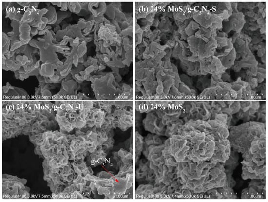
Figure 2.
SEM images of (a) pure g-C3N4, (b) 24% MoS2/g-C3N4-S, (c) 24% MoS2/g-C3N4-U and (d) isolated MoS2.
The microstructures of pure g-C3N4, MoS2, and MoS2/g-C3N4 composites were investigated by transmission electron microscopy (TEM) and high-resolution TEM (HRTEM), as shown in Figure 3. The pristine g-C3N4 sample (Figure 3a,e) exhibits a typical stacked nanosheet morphology with curled and transparent edges, reflecting its characteristic layered structure and low electron density.
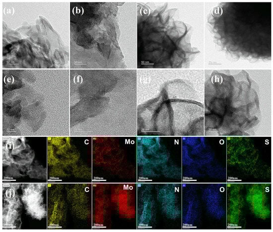
Figure 3.
TEM and HRTEM images of (a,e) pure g-C3N4, (b,f) 24% MoS2/g-C3N4-S, (c,g) 24% MoS2/g-C3N4-U and (d,h) isolated MoS2; EDS elemental mapping images of (i) 24% MoS2/g-C3N4-S and (j) 24% MoS2/g-C3N4-U.
For the 24% MoS2/g-C3N4-S composite synthesized under stirring conditions (Figure 3b,f), the lamellar morphology of g-C3N4 is largely preserved, as evidenced by the sharp and planar edges visible in the TEM image. However, no well-defined lattice fringes corresponding to MoS2 are observed in the HRTEM image (Figure 3f), suggesting that MoS2 is highly dispersed and possibly amorphous or extremely thin, which renders its crystallinity difficult to resolve. Such high dispersion is favorable for increasing the active surface area and enhancing interfacial electron transfer.
In contrast, the 24% MoS2/g-C3N4-U sample (Figure 3c,g) prepared without stirring displays a distinctly different morphology. The nanosheets appear more clustered and curled into flower-like stacks, closely resembling the morphology of pure MoS2 (Figure 3d,h). Furthermore, the HRTEM image (Figure 3g) reveals clear lattice fringes, indicating locally aggregated and well-crystallized MoS2 domains. These observations suggest that without stirring, MoS2 preferentially nucleates and grows independently, leading to phase segregation and insufficient integration with the g-C3N4 matrix.
Elemental distributions in the composites were further examined via energy-dispersive X-ray spectroscopy (EDS) mapping (Figure 3i,j). In the stirred sample (Figure 3i), Mo, S, C, and N elements are evenly dispersed throughout the field of view, confirming the uniform incorporation of MoS2 into the g-C3N4 framework. By contrast, the unstirred composite (Figure 3j) exhibits pronounced aggregation of Mo and S elements, consistent with localized MoS2 clustering. These results reaffirm the essential role of stirring in promoting homogeneous precursor distribution and enabling uniform MoS2 nucleation during hydrothermal synthesis.
2.1.3. Elemental Composition
Table 1 summarizes the atomic and weight percentages of key elements (C, N, O, S, Mo) in 24% MoS2/g-C3N4 composites prepared under stirring (S) and unstirring (U) conditions, as obtained by EDS mapping and ICP-MS analysis. These quantitative findings provide important insights into the structural and photocatalytic differences revealed in XRD, SEM, and TEM results.

Table 1.
The atomic and mass ration of composite elements in 24% MoS2/g-C3N4-S and 24% MoS2/g-C3N4-U samples obtained from EDS Mapping and ICP-MS.
In the stirred sample (24% MoS2/g-C3N4-S), EDS analysis shows that nitrogen and carbon dominate the atomic composition (56.27% and 38.59%, respectively), while Mo and S account for only 0.77% and 2.67%, respectively. The corresponding weight ratios of Mo (5.11%) and S (5.95%) confirm that MoS2 is present in a small but uniformly distributed amount across the g-C3N4 surface. The Mo content measured by ICP-MS (6.25%) is in excellent agreement with the EDS result. These values are consistent with the XRD pattern showing strong g-C3N4 peaks and nearly invisible MoS2 signals, as well as the TEM images where lattice fringes of MoS2 are difficult to resolve—supporting the conclusion that MoS2 is highly dispersed, possibly amorphous, and forms a strong interface with the g-C3N4 substrate.
In contrast, the unstirred sample (24% MoS2/g-C3N4-U) shows a drastically different profile. The atomic percentages of Mo (11.4%) and S (46.28%) are significantly higher, while those of C (16.28%) and N (14.72%) are much lower. In terms of weight ratio, Mo and S reach 34.6% and 46.95%, respectively, indicating a strong enrichment of MoS2 within the detected region. This aligns with the intense MoS2 diffraction peaks in XRD, clearly visible MoS2 lattice fringes in HRTEM, and dense, flower-like morphology in SEM and TEM images—suggesting severe aggregation and poor integration with g-C3N4.
These structural and compositional differences directly correlate with photocatalytic performance. The sample synthesized with stirring exhibits superior hydrogen evolution activity, owing to the highly dispersed MoS2 nanostructures that form extensive heterojunction interfaces with g-C3N4, enhancing charge separation and surface reactivity. On the other hand, in the absence of stirring, MoS2 tends to aggregate and dominates the surface, reducing the number of effective interfacial contact sites and thus compromising the charge-transfer efficiency and catalytic activity.
2.1.4. Specific Surface Area Analysis and Correlation with Structural Properties
Table 2 summarizes the Brunauer–Emmett–Teller (BET) surface areas of the prepared samples. The pure g-C3N4 sample exhibits the highest specific surface area of 62.60 m2/g, reflecting its intrinsic lamellar structure with loosely stacked nanosheets and high porosity. After incorporation of 24 wt% MoS2, the BET surface area decreases slightly to 48.90 m2/g for the stirred composite (24% MoS2/g-C3N4-S), while a more drastic reduction to 27.68 m2/g is observed for the unstirred composite (24% MoS2/g-C3N4-U). The pure MoS2 sample exhibits the lowest BET surface area of 17.69 m2/g, which is attributed to its characteristic flower-like microsphere morphology. This structure consists of tightly stacked multilayered MoS2 nanosheets forming dense spherical aggregates, as observed in the SEM and TEM images. Such a morphology limits the accessible surface area and reduces the number of exposed active sites for photocatalytic reactions.
Table 2.
BET surface areas of prepared samples.
These surface area differences closely align with the previously discussed morphological features. The stirred sample maintains a relatively high surface area due to the uniform deposition of highly dispersed MoS2 nanostructures onto the g-C3N4 matrix, as evidenced by EDS mapping and the absence of significant MoS2 diffraction peaks in XRD. The preservation of the lamellar g-C3N4 morphology in SEM and TEM further supports this structural integrity. In contrast, the unstirred sample exhibits severe MoS2 agglomeration, leading to the collapse or blockage of g-C3N4’s porous network, thereby reducing the accessible surface area. This aggregation is also reflected in the high Mo and S elemental content detected in localized regions by EDS.
From a photocatalytic perspective, a larger specific surface area generally provides more active sites and improves light harvesting and reactant adsorption. Thus, the relatively higher BET surface area of the stirred composite is an important contributing factor to its superior hydrogen evolution performance. The combination of structural uniformity, better interfacial contact, and higher accessible surface reinforces the advantages of stirring-assisted hydrothermal synthesis in optimizing both material structure and catalytic activity.
2.2. Characterization of Photoelectrochemical Test Results
2.2.1. UV–Vis, PL, and TRPL Analysis
As shown in Figure 4a, pure g-C3N4 exhibits a clear absorption edge at ~460 nm, indicating limited visible-light utilization. MoS2 shows broad absorption across the UV–Vis range. The 24% MoS2/g-C3N4-S composite demonstrates enhanced absorption intensity, especially in the visible region, compared to pure g-C3N4. The enhancement is less significant in the unstirred composite, suggesting weaker light-harvesting efficiency.
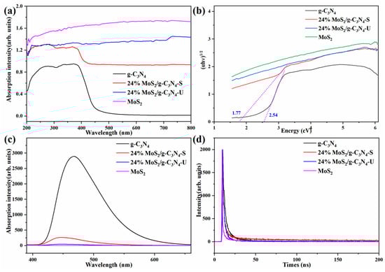
Figure 4.
(a) UV–Vis absorption spectra of g-C3N4, 24% MoS2/g-C3N4 composites (stirred and unstirred), and MoS2. (b) Tauc plots for bandgap estimation with n = 1/2: g-C3N4 (Eg ≈ 2.54 eV), stirred composite (Eg ≈ 1.77 eV). (c) Steady-state photoluminescence (PL) spectra to assess carrier recombination. (d) Time-resolved photoluminescence (TRPL) decay curves of all samples.
Figure 4b shows the Tauc plots (n = 1/2) of the prepared samples for estimating their indirect optical bandgaps (Eg). The pure g-C3N4 sample exhibits an Eg of approximately 2.54 eV, consistent with reported values for this metal-free photocatalyst. For the stirred composite (24% MoS2/g-C3N4-S), the bandgap is reduced to 1.77 eV, accompanied by a significant enhancement in optical absorption, indicating stronger interfacial interaction between g-C3N4 and MoS2. In contrast, the unstirred composite (24% MoS2/g-C3N4-U) shows no well-defined MoS2-related indirect transition in the n = 1/2 plot, suggesting that MoS2 in this sample does not exhibit a clear indirect band edge due to aggregation effects. Since MoS2 in the composites is ultrathin and highly dispersed, its optical transition characteristics are better captured in the n = 2 Tauc plots (Figure S1), corresponding to direct-like transitions. In this case, the extracted Eg values are 1.47 eV for pure MoS2, 1.75 eV for the unstirred composite, and 1.87 eV for the stirred composite. The blue-shift in the stirred sample compared with pure MoS2 reflects enhanced dispersion and thickness reduction, leading to a more pronounced direct-like transition onset.
PL spectra (Figure 4c) provide insight into carrier recombination behavior. Pure g-C3N4 displays the strongest emission, indicating rapid charge recombination. The PL intensity of the stirred composite is significantly quenched, suggesting enhanced separation of photogenerated carriers. The unstirred composite shows less PL suppression, confirming that insufficient mixing limits interface formation and charge extraction.
TRPL results (Figure 4d, Table 3) reveal more details of carrier dynamics. The average carrier lifetime (τave) of g-C3N4 is 4.89 ns, which increases to 10.89 ns in the stirred sample. However, average lifetime alone does not fully represent separation efficiency. Notably, in the stirred composite, the slow-decay component τ2 reaches 42.7 ns and accounts for 48.43% (α2), indicating a large portion of electrons are effectively extracted before recombination. In contrast, the unstirred sample has a much shorter τ2 (11.35 ns) and lower α2 (33.13%), implying faster recombination and inefficient charge utilization—likely caused by MoS2 aggregation and interfacial discontinuity, as supported by EDS and TEM data.
Table 3.
PL lifetimes of g-C3N4, 24% MoS2/g-C3N4-S, 24% MoS2/g-C3N4-U and MoS2.
These findings are consistent with XRD, SEM, and TEM analyses. The stirred sample exhibits homogeneous MoS2 distribution, better crystallinity of g-C3N4, and intimate MoS2/g-C3N4 contact—creating effective heterojunctions that facilitate bandgap tuning, broaden absorption, and prolong carrier lifetimes. In contrast, the unstirred composite exhibits flower-like MoS2 aggregation and limited heterointerface formation, which lead to stronger recombination and inferior optical and catalytic performance.
2.2.2. EPR, EIS, Photocurrent, Mott–Schottky
Figure 5a shows the electron paramagnetic resonance (EPR) spectra of g-C3N4 and 24% MoS2/g-C3N4-S samples, measured under dark conditions. The observed signal at g ≈ 2.0027 typically corresponds to unpaired electrons associated with structural defects, such as nitrogen vacancies, or electrons trapped in localized π-conjugated defect states within the g-C3N4 matrix. Compared to pure g-C3N4, the stirred composite exhibits a significantly enhanced EPR signal intensity, indicating a higher density of defect-related paramagnetic centers. This suggests that the introduction of MoS2 and the formation of a heterojunction facilitate charge redistribution and generate more surface traps or localized electron states. These trapped or defect-bound electrons are beneficial for suppressing rapid electron–hole recombination, thereby contributing to the prolonged lifetime and enhanced reduction ability of photogenerated electrons. Electrochemical impedance spectroscopy (EIS) results are presented in Figure 5b. The Nyquist plots show that the stirred composite exhibits the smallest arc radius, indicating the lowest interfacial charge transfer resistance. In contrast, both pristine g-C3N4 and the unstirred composite exhibit larger arcs, implying poorer charge transfer kinetics across the interface.
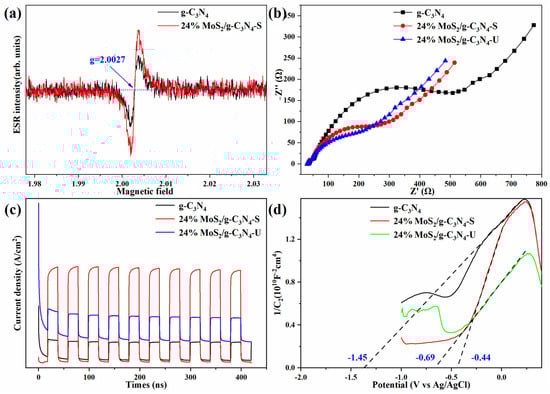
Figure 5.
(a) Electron paramagnetic resonance (EPR) spectra. (b) Electrochemical impedance spectroscopy (EIS) Nyquist plots. (c) Transient photocurrent response under chopped light irradiation. (d) Mott–Schottky plots for determining flat-band potential and semiconductor type.
Figure 5c displays photocurrent response curves under chopped light illumination. The stirred composite shows the highest and most stable current density over repeated light on–off cycles, reflecting superior photo response, charge carrier separation, and surface reaction kinetics. The unstirred composite shows moderate enhancement but still lower photocurrent than the stirred sample.
Band edge analysis based on Mott–Schottky plots (Figure 5d) shows that the conduction band (CB) of g-C3N4 remains stable at −1.45 eV, which is consistent with previous studies [8,21,24,32], while the CB positions for the stirred and unstirred composites are −0.44 eV and −0.69 eV, respectively. The upward CB shift in the stirred sample is consistent with more efficient electron transport and improved heterojunction formation.
Collectively, these results confirm that the 24% MoS2/g-C3N4-S composite synthesized under stirring possesses superior charge transfer efficiency, enhanced photogenerated electron density, and improved redox potential—all contributing to its outstanding photocatalytic hydrogen evolution performance.
2.3. Photocatalytic H2 Evolution Performance
Figure 6a shows the time-dependent H2 production curves over 5 h. Both pristine g-C3N4 and MoS2 exhibit poor hydrogen evolution activity, confirming their limited standalone photocatalytic performance. In contrast, MoS2/g-C3N4 composites with different loadings show enhanced H2 production, with the 24% MoS2/g-C3N4-S sample achieving the highest H2 yield. The unstirred 24% sample performs significantly worse, indicating that stirring facilitates homogeneous MoS2 dispersion and effective heterojunction formation, which promotes carrier mobility and exposure of active sites.
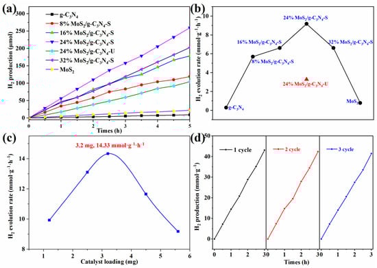
Figure 6.
(a) Time-dependent H2 production over various MoS2/g-C3N4 composites (with and without stirring). (b) Hydrogen evolution rates of all samples. (c) Effect of catalyst loading (1–5.6 mg) on the H2 evolution rate using the optimal 24% MoS2/g-C3N4-S catalyst. (d) Reusability test of the 24% MoS2/g-C3N4-S over three consecutive cycles. Each cycle test was conducted by subjecting the catalyst to a 3-h reaction period followed by vacuum treatment before starting the next cycle to assess the stability and reusability of the catalyst.
Figure 6b summarizes the corresponding hydrogen evolution rates. The rate increases from 8% to 24% MoS2 loading, peaking at over 10 mmol·g−1·h−1, then slightly decreases at 32%, likely due to excessive MoS2 coverage causing light-shielding or blocking catalytic sites. Notably, the unstirred 24% sample exhibits a much lower rate than its stirred counterpart, reaffirming the critical role of stirring in structural optimization.
Figure 6c explores the effect of catalyst dosage using the optimal 24% MoS2/g-C3N4-S sample. The H2 evolution rate reaches a maximum of 14.33 mmol·g−1·h−1 at a loading of 3.2 mg. Higher amounts result in reduced performance, possibly due to light scattering, mass transfer limitations, or reduced photon penetration. Compared to the HER rate values provided in Table S1, this performance is notably higher than many other reported composites, including those synthesized through conventional methods like hydrothermal calcination or ultrasonic dispersion. For example, the HER rate for similar composites such as MoS2/g-C3N4 (no stirring) and MoS2/g-C3N4 with calcination falls in the range of 0.2 to 12 mmol·g−1·h−1, while your composite demonstrates a significant enhancement in photocatalytic efficiency, clearly surpassing these values. This highlights the effectiveness of the stirring-assisted in situ synthesis method in optimizing MoS2 dispersion and enhancing charge separation, leading to superior hydrogen evolution performance.
While compared with previous studies, the performance lies within a moderate range compared to other advanced photocatalysts. Several factors could be limiting the enhancement of HER activity in our system: (1) MoS2 dispersion and edge exposure, (2) charge recombination, (3) electronic conductivity and the MoS2-g-C3N4 interface, and (4) catalyst stability. Future work will focus on optimizing MoS2 loading, enhancing charge separation efficiency, improving electron transport, and enhancing long-term stability.
2.4. Mechanism Explanation
Figure 7 depicts the mechanism of photocatalytic hydrogen evolution over MoS2/g-C3N4 composites synthesized under stirred and unstirred hydrothermal conditions, focusing on band alignment, charge dynamics, and interface interactions. Mott–Schottky measurements show that pristine g-C3N4 has a flat-band potential of −1.45 V (vs. Ag/AgCl), indicating a highly negative conduction band edge suitable for efficient proton reduction. MoS2, on the other hand, exhibits a conduction band (CB) edge at −0.44 V for the stirred sample and −0.69 V for the unstirred composite, with bandgaps of 1.47 eV (MoS2), 1.75 eV (unstirred composite), and 1.87 eV (stirred composite), respectively. These findings suggest that MoS2 in the stirred sample adopts a more direct-like transition due to its ultrathin, highly dispersed structure. Band position comparisons reveal that both samples exhibit characteristics consistent with a Type-II heterojunction structure [36,37,38], where g-C3N4 valence band (VB) and CB are positioned entirely above those of MoS2, facilitating efficient charge separation. The stirred composite (24% MoS2/g-C3N4-S) demonstrates a positively shifted flat-band potential (−0.44 V) compared to the unstirred sample, which shows a more negative −0.69 V, suggesting improved interfacial band alignment in the stirred sample.
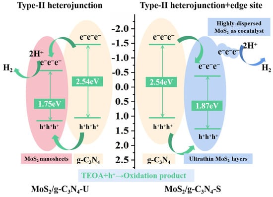
Figure 7.
Schematic illustration of the photogenerated charge separation and transfer in MoS2/g-C3N4 heterostructures.
In addition, photocatalytic tests show a significant performance gap: the stirred sample exhibits a much higher H2 evolution rate (up to 14.33 mmol·g−1·h−1), far surpassing the unstirred counterpart. This discrepancy is primarily attributed to the enhanced MoS2 dispersion and the presence of active co-catalytic edge sites in the stirred sample, rather than differences in band structure alone.
XRD, SEM, TEM, and EDS mapping confirm that the stirred sample retains the crystallinity of g-C3N4, with highly dispersed MoS2 nanosheets and abundant edge exposure on the g-C3N4 surface. BET measurements further show an increased surface area, providing more catalytic sites for the hydrogen evolution reaction.
Electrochemical analyses reinforce these findings: EIS reveals reduced charge transfer resistance, and transient photocurrent responses indicate enhanced carrier separation. The Mott–Schottky plot suggests beneficial interfacial band bending in the stirred sample, facilitating electron transfer. EPR and TRPL data further support the improved charge carrier density and lifetime in the stirred composite.
While both systems are classified as Type-II heterojunctions, the stirred composite introduces a synergistic enhancement mechanism: highly dispersed MoS2 nanosheets act as co-catalytic edge sites, enabling fast photogenerated electron transfer and providing efficient active sites for H2 evolution. These edge sites overcome the recombination limitations typically associated with Type-I heterojunctions and further enhance the catalytic activity.
Therefore, the significantly improved photocatalytic performance of the MoS2/g-C3N4-S composite can be attributed to the synergistic effects of multiple structural and electronic factors. First, the formation of a structurally favorable Type-II heterojunction facilitates efficient charge migration, with photogenerated electrons transferring smoothly from the g-C3N4 conduction band into MoS2. Second, the highly dispersed MoS2 nanosheets expose abundant edge sites that act as active co-catalytic centers for the H2 evolution reaction, enhancing the overall catalytic performance. Third, the optimized morphology and improved interfacial contact between g-C3N4 and MoS2 significantly promote charge carrier separation and mobility. These combined effects suppress electron–hole recombination and optimize electron transfer, leading to a remarkable improvement in photocatalytic hydrogen evolution efficiency.
3. Materials and Methods
3.1. Materials
Thiourea (CH4N2S, analytical reagent grade), ammonium molybdate tetrahydrate ((NH4)6Mo7O24·4H2O, analytical reagent grade), triethanolamine (C6H15NO3, analytical reagent grade), and absolute ethanol (C2H6O, analytical reagent grade) were all purchased from Sinopharm Chemical Reagent Co., Ltd., Shanghai, China. N,N-Dimethylformamide (C3H7NO, analytical reagent grade) was obtained from Aladdin Industrial Corporation, City, China. All chemicals were used as received without further purification.
3.2. Synthesis of the Photocatalyst
All chemicals used in this study were of analytical reagent grade and used without further purification.
Figure 8 illustrates the synthesis procedure used in this study. We employed a stirred hydrothermal method to improve uniformity during the growth of MoS2/g-C3N4 composites. We hypothesize that stirring inhibits MoS2 crystallization in solution, allowing nucleation mainly on the g-C3N4 substrate, thus forming highly dispersed and strongly interacting MoS2/g-C3N4 composites. In contrast, traditional hydrothermal synthesis permits MoS2 nucleation both on g-C3N4 and in solution, leading to flower-like MoS2 structures attached to g-C3N4. The detailed information are as follow.
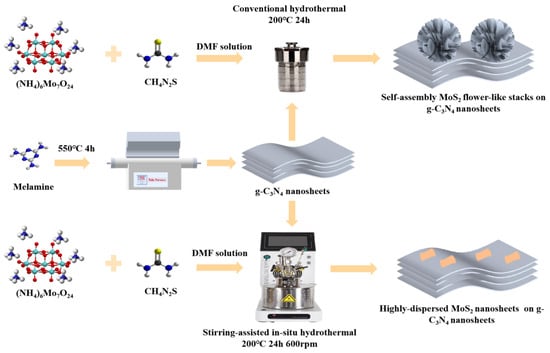
Figure 8.
Proposed schematic illustration of the stirring-assisted in situ hydrothermal synthesis of MoS2/g-C3N4 composite.
3.2.1. Synthesis of g-C3N4
As shown in Figure 8, the bulk g-C3N4 was synthesized via direct thermal condensation of melamine. Specifically, 0.6 g of melamine powder was placed in a covered alumina crucible and heated in a tubular furnace under continuous air flow. The sample was heated to 550 °C at a rate of 5 °C min−1 and held at this temperature for 4 h. After natural cooling to room temperature, the resulting light-yellow solid was collected and ground into fine powder for subsequent use.
3.2.2. Synthesis of MoS2@g-C3N4 Composite Catalysts
In a typical synthesis as show in Figure 8, 0.6 g of as-prepared g-C3N4 powder was dispersed in 90 mL of DMF under magnetic stirring and then ultrasonicated for 30 min. Subsequently, 120 mg of ammonium molybdate tetrahydrate ((NH4)6Mo7O24·4H2O) was added to the suspension and ultrasonicated for another 30 min. Then, 240 mg of thiourea was introduced and the suspension was again ultrasonicated for 30 min to ensure thorough mixing.
After the final sonication, the suspension was gently shaken and immediately transferred to a Teflon-lined stainless steel autoclave equipped with a magnetic stirrer. The mixture was first stirred at room temperature at 600 rpm for 4 h, followed by hydrothermal treatment at 200 °C for 24 h under continuous stirring (600 rpm). After natural cooling to room temperature (~2 h), the product was collected by vacuum filtration through moistened filter paper. The solid was sequentially washed with DMF, absolute ethanol, and deionized water to remove unreacted precursors and residues. Finally, the sample was dried in a vacuum oven at 60 °C for 12 h and ground into fine powder for storage and further characterization.
3.2.3. Sample Variation and Control Design
To investigate the effect of MoS2 loading and stirring conditions on photocatalytic performance, a series of MoS2@g-C3N4 composites were prepared by varying the precursor amounts to achieve different MoS2 loadings: 8%, 16%, 24%, and 32% by weight. All samples were prepared under the same conditions except for the amount of precursors. Samples synthesized with magnetic stirring during the hydrothermal process were labeled as “-S” (e.g., 24% MoS2/g-C3N4-S), while those synthesized without stirring were denoted as “-U” (e.g., 24% MoS2/g-C3N4-U), serving as the unstirred control. Pure g-C3N4 and pure MoS2 were also synthesized and included as reference samples.
3.3. Characterization
The phase structures of the as-prepared samples were identified by X-ray diffraction (XRD) using a Bruker D8 Advance diffractometer (Bruker AXS GmbH, Karlsruhe, Germany) equipped with Cu Kα radiation (λ = 1.5406 Å), operated at 40 kV and 40 mA. Surface morphology and microstructural features were examined through field-emission scanning electron microscopy (FESEM, Hitachi S-4800, Hitachi High-Technologies Corporation, Tokyo, Japan) and high-resolution transmission electron microscopy (HRTEM, JEOL JEM-2100F, JEOL Ltd., Tokyo, Japan). Elemental mapping and local composition were further characterized by energy-dispersive X-ray spectroscopy (EDS) integrated into the TEM system.
The specific surface area and porosity were evaluated via nitrogen adsorption–desorption isotherms collected at 77 K using a Micromeritics ASAP 2020 system (Micromeritics Instrument Corporation, Norcross, GA, USA). Molybdenum content in the composite materials was quantitatively determined by inductively coupled plasma optical emission spectrometry (ICP-OES, Agilent 5110, Agilent Technologies Inc., Santa Clara, CA, USA).
3.4. Photoelectrochemical Test
To investigate optical and photoelectrochemical behaviors, UV–Vis diffuse reflectance spectra (DRS) were recorded on a Shimadzu UV-2600 instrument (Shimadzu Corporation, Kyoto, Japan), and the bandgap energy was calculated based on the corresponding Tauc plots. Steady-state photoluminescence (PL) spectra were measured with a Hitachi F-7000 spectrofluorometer (excitation wavelength: 325 nm, Hitachi, Tokyo, Japan) to study carrier recombination. Carrier lifetimes were estimated through time-resolved PL (TRPL) spectroscopy using an Edinburgh FLS980 fluorescence spectrometer (Edinburgh Instruments, Edinburgh, UK).
Electron paramagnetic resonance (EPR) was employed using a Bruker EMXplus (Bruker Corporation, Billerica, United States) to detect paramagnetic surface species and defect signals. Electrochemical impedance spectroscopy (EIS), transient photocurrent measurements, and Mott–Schottky (M–S) analyses were conducted on a CHI660E electrochemical workstation (CH Instruments, Shanghai, China) in a standard three-electrode configuration, where a Pt wire served as the counter electrode, Ag/AgCl as the reference electrode, and the sample-coated glassy carbon electrode as the working electrode. All electrochemical tests were carried out in 0.2 M Na2SO4 solution under dark or illuminated conditions, with illumination provided by a 300 W xenon lamp equipped with an AM 1.5G filter.
3.5. Photocatalytic Activity Evaluation
Photocatalytic hydrogen evolution experiments were carried out using a Labsolar-6A automated photocatalytic analysis workstation (Perfectlight, Beijing, China). In a typical run, the catalyst was dispersed in 50 mL of aqueous solution containing 20 vol% triethanolamine (TEOA), which served as a sacrificial electron donor. Prior to illumination, the suspension was sonicated for 10 min and purged with high-purity nitrogen gas for 30 min to remove residual oxygen.
A 300 W xenon arc lamp (PLS-SXE300D, Perfectlight, Beijing, China) was used as the irradiation source without any optical filter, thus providing full-spectrum light. The reaction suspension was continuously stirred using a magnetic stirrer to maintain homogeneity and prevent catalyst sedimentation. To examine the influence of photocatalyst dosage on hydrogen production, a series of tests were conducted using catalyst masses ranging from 2.0 to 5.6 mg under otherwise identical conditions.
The evolved hydrogen was collected and quantified using the gas analysis interface of the Labsolar-6A system, which is equipped with a built-in gas chromatograph (Fuli GC-9790Plus, Fuli, Hangzhou, China). The GC system utilized a 5A molecular sieve column and a thermal conductivity detector (TCD), with nitrogen as the carrier gas. The amount of hydrogen generated was calculated by comparing the GC peak areas with standard calibration curves.
The rate of hydrogen evolution (RH2) was calculated using the following equation:
where nH2 is the amount of hydrogen (in mmol), m is the mass of the photocatalyst (in grams), and t is the irradiation time (in hours).
For catalyst stability evaluation, the optimized sample was subjected to four consecutive 5-h photocatalytic cycles under identical experimental conditions. After each cycle, the photocatalyst was recovered by centrifugation, washed thoroughly with deionized water and ethanol, dried at 60 °C, and reused in the subsequent run. The durability of the catalyst was assessed by comparing the hydrogen production rates across the repeated cycles.
4. Conclusions
This study proposes a stirring-assisted hydrothermal in situ synthesis strategy to construct a MoS2/g-C3N4 heterojunction photocatalyst with highly dispersed MoS2 nanosheets. Unlike conventional static hydrothermal methods, the introduction of agitation during synthesis significantly improves precursor mixing, facilitates the uniform nucleation and growth of MoS2, and ensures the exposure of abundant catalytic edge sites on the g-C3N4 surface. Structural characterizations confirm that the stirred samples exhibit superior interfacial contact, reduced aggregation, and well-defined lattice continuity, while the unstirred samples suffer from MoS2 clustering and poor interface formation. Multidimensional characterizations, including XRD, SEM/TEM, EDS mapping, BET, and ICP analyses, together with optoelectronic measurements (UV–Vis, TRPL, EIS, EPR, Mott–Schottky), collectively demonstrate that the high dispersion of MoS2 facilitates charge separation, improves electron mobility, and provides abundant active sites at the MoS2 edges for hydrogen evolution. As a result, the optimized 24% MoS2/g-C3N4-S catalyst achieves a maximum hydrogen production rate of 14.33 mmol·g−1·h−1 at a catalyst dosage of 3.2 mg, accompanied by excellent cycling stability. The superior performance is attributed to three critical factors: (i) the stirring-assisted in situ method enables controlled interface construction and heterojunction formation; (ii) the highly exposed edge-rich MoS2 structure functions as an effective co-catalyst and electron extraction channel; and (iii) the engineered morphology enhances visible-light absorption and charge migration pathways. Overall, this work offers a novel and scalable approach to co-catalyst dispersion and interface engineering, providing mechanistic insights into heterojunction design for efficient solar-to-hydrogen energy conversion using non-noble metal materials.
Supplementary Materials
The following supporting information can be downloaded at https://www.mdpi.com/article/10.3390/catal15090808/s1, Figure S1: Tauc plots for bandgap estimation with n = 2; Table S1: Comparison of photocatalytic H2 evolution performance of reported MoS2/g-C3N4 composites.
Author Contributions
Conceptualization, investigation, methodology, and writing—original draft preparation, S.L. and Y.M.; methodology and investigation, Y.C. and H.Z.; writing—review and editing and supervision, T.W. and G.Y. All authors have read and agreed to the published version of the manuscript.
Funding
This research was supported by the project, No. LZ21E060002, of Zhejiang Provincial Natural Science Foundation of China, the project, No. 52203300, of Youth Foundation of the National Natural Science China, the project, No. 2023H005, of Ningbo International Science & Technology Cooperation Program, and the project, No. 2023J366 Ningbo Natural Science Foundation.
Data Availability Statement
Data are contained within the article/Supplementary Materials.
Conflicts of Interest
The authors declare no conflicts of interest.
References
- Gunawan, D.; Zhang, J.; Li, Q.; Toe, C.Y.; Scott, J.; Antonietti, M.; Guo, J.; Amal, R. Materials Advances in Photocatalytic Solar Hydrogen Production: Integrating Systems and Economics for a Sustainable Future. Adv. Mater. 2024, 36, 2404618. [Google Scholar] [CrossRef]
- Abhishek, B.; Jayarama, A.; Rao, A.S.; Nagarkar, S.S.; Dutta, A.; Duttagupta, S.P.; Prabhu, S.S.; Pinto, R. Challenges in Photocatalytic Hydrogen Evolution: Importance of Photocatalysts and Photocatalytic Reactors. Int. J. Hydrogen Energy 2024, 81, 1442–1466. [Google Scholar] [CrossRef]
- Yuan, Y.; Zhang, L.; Xing, J.; Utama, M.I.B.; Lu, X.; Du, K.; Li, Y.; Hu, X.; Wang, S.; Genç, A.; et al. High-Yield Synthesis and Optical Properties of g-C3N4. Nanoscale 2015, 7, 12343–12350. [Google Scholar] [CrossRef]
- Aggarwal, P.; Sarkar, D.; Menezes, P.W.; Awasthi, K. Boosting Electrochemical Hydrogen Evolution Activity of MoS2 Nanosheets via Facile Decoration of Au Overlayer. Int. J. Hydrogen Energy 2022, 47, 41795–41805. [Google Scholar] [CrossRef]
- Zhu, J.; Wang, Z.-C.; Dai, H.; Wang, Q.; Yang, R.; Yu, H.; Liao, M.; Zhang, J.; Chen, W.; Wei, Z.; et al. Boundary Activated Hydrogen Evolution Reaction on Monolayer MoS2. Nat. Commun. 2019, 10, 1348. [Google Scholar] [CrossRef]
- Mamiyev, Z.; Balayeva, N.O. Metal Sulfide Photocatalysts for Hydrogen Generation: A Review of Recent Advances. Catalyst 2022, 12, 1316. [Google Scholar] [CrossRef]
- Wei, X.; Wang, M.; Ali, S.; Wang, J.; Zhou, Y.; Zuo, R.; Zhong, Q.; Zhan, C. Enhanced Photocatalytic H2 Evolution on G-C3N4 Nanosheets Loaded with Nitrogen-Doped MoS2 as Cocatalysts. Int. J. Hydrogen Energy 2024, 89, 691–702. [Google Scholar] [CrossRef]
- Li, X.; Zhang, Y.; Wei, T.; Wang, C.; Wan, J.; Tang, Y.; Guo, M.; Ma, Y.; Yang, Y. Boosting the Photocatalytic Performance of G-C3N4 through MoS2 Nanotubes with the Cavity Enhancement Effect. Langmuir 2024, 40, 11160–11172. [Google Scholar] [CrossRef]
- Xing, F.; Wang, C.; Liu, S.; Jin, S.; Jin, H.; Li, J. Interfacial Chemical Bond Engineering in a Direct Z-Scheme g-C3N4/MoS2 Heterojunction. ACS Appl. Mater. Interfaces 2023, 15, 11731–11740. [Google Scholar] [CrossRef]
- Liu, X.; Wang, B.; Liu, M.; Liu, S.; Chen, W.; Gao, L.; Li, X. In Situ Growth of Vertically Aligned Ultrathin MoS2 on Porous G-C3N4 for Efficient Photocatalytic Hydrogen Production. Appl. Surf. Sci. 2021, 554, 149617. [Google Scholar] [CrossRef]
- Wei, Z.; Shen, X.; Ji, Y.; Yang, Z.; Wang, T.; Li, S.; Zhu, M.; Tian, Y. Synthesis of Novel MoS2/g-C3N4 Nanocomposites for Enhanced Photocatalytic Activity. J. Mater. Sci. Mater. Electron. 2020, 31, 15885–15895. [Google Scholar] [CrossRef]
- Zhou, B.; Yang, B.; Waqas, M.; Xiao, K.; Zhu, C.; Wu, L. Design of a p–n Heterojunction in 0D/3D MoS2/g-C3N4 Composite for Boosting the Efficient Separation of Photogenerated Carriers with Enhanced Visible-Light-Driven H2 Evolution. RSC Adv. 2020, 10, 19169–19177. [Google Scholar] [CrossRef]
- Liu, Y.; Zhang, H.; Ke, J.; Zhang, J.; Tian, W.; Xu, X.; Duan, X.; Sun, H.; Tade, M.O.; Wang, S. 0D (MoS2)/2D (g-C3N4) Heterojunctions in Z-Scheme for Enhanced Photocatalytic and Electrochemical Hydrogen Evolution. Appl. Catal. B Environ. 2018, 228, 64–74. [Google Scholar] [CrossRef]
- Jia, T.; Deng, Z.; Yu, D.; Fu, F.; Zhang, Q.; Wang, Y.; Hu, J.; Li, J.; Lee, J.H. Anchoring MoS2 Microflowers on Oxygen-Doped g-C3N4 Nanosheets to Construct Z-Scheme Hybrid Composites for Photocatalytic Hydrogen Production. Ionics 2024, 30, 3417–3429. [Google Scholar] [CrossRef]
- Tian, J.; Chen, Z.; Jing, J.; Feng, C.; Sun, M.; Li, W. Enhanced Photocatalytic Performance of the MoS2/g-C3N4 Heterojunction Composite Prepared by Vacuum Freeze Drying Method. J. Photochem. Photobiol. A Chem. 2020, 390, 112260. [Google Scholar] [CrossRef]
- Kadi, M.W.; Mohamed, R.M.; Ismail, A.A. Thin-Layer g-C3N4 Nanosheet Decoration with MoS2 Nanoparticles as a Highly Efficient Photocatalyst in the H2 Production Reaction. J. Nanoparticle Res. 2020, 22, 156. [Google Scholar] [CrossRef]
- Li, W.; Wang, L.; Zhang, Q.; Chen, Z.; Deng, X.; Feng, C.; Xu, L.; Sun, M. Fabrication of an Ultrathin 2D/2D C3N4/MoS2 Heterojunction Photocatalyst with Enhanced Photocatalytic Performance. J. Alloys Compd. 2019, 808, 151681. [Google Scholar] [CrossRef]
- Zhang, M.; Yang, G.; Liu, S.; Yu, J.; Li, H.; Zhang, L.; Chen, Y.; Guo, R.; Wu, T. MoS2 Quantum Dots Based MoS2/HKUST-1 Composites for the Highly Efficient Catalytic Oxidation of Elementary Mercury. J. Environ. Sci. 2022, 116, 163–174. [Google Scholar] [CrossRef] [PubMed]
- Tian, Y.; Ge, L.; Wang, K.; Chai, Y. Synthesis of Novel MoS2/g-C3N4 Heterojunction Photocatalysts with Enhanced Hydrogen Evolution Activity. Mater. Charact. 2014, 87, 70–73. [Google Scholar] [CrossRef]
- Ge, L.; Han, C.; Xiao, X.; Guo, L. Synthesis and Characterization of Composite Visible Light Active Photocatalysts MoS2–g-C3N4 with Enhanced Hydrogen Evolution Activity. Int. J. Hydrogen Energy 2013, 38, 6960–6969. [Google Scholar] [CrossRef]
- Yuan, Y.-J.; Shen, Z.; Wu, S.; Su, Y.; Pei, L.; Ji, Z.; Ding, M.; Bai, W.; Chen, Y.; Yu, Z.-T.; et al. Liquid Exfoliation of G-C3N4 Nanosheets to Construct 2D-2D MoS2/g-C3N4 Photocatalyst for Enhanced Photocatalytic H2 Production Activity. Appl. Catal. B Environ. 2019, 246, 120–128. [Google Scholar] [CrossRef]
- Wang, M.; Ju, P.; Zhao, Y.; Li, J.; Han, X.; Hao, Z. In Situ Ion Exchange Synthesis of MoS2/g-C3N4 Heterojunctions for Highly Efficient Hydrogen Production. New J. Chem. 2018, 42, 910–917. [Google Scholar] [CrossRef]
- Ding, J.; Song, L.; Li, X.; Chen, L.; Li, X.; Sun, J.; Zhang, X.; Wang, Y.; Tian, X. Interfacial Engineering of the Platinum/Molybdenum Disulfide/Graphitic Carbon Nitride Composite for Enhanced Photocatalytic Hydrogen Production. ACS Appl. Energy Mater. 2022, 5, 8800–8811. [Google Scholar] [CrossRef]
- Ding, J.; Wang, Y.; Guo, S.; Zhang, Y.; Xin, X.; Tang, S.; Liu, S.; Li, X. Designing Efficient MoS2/G-C3N4 Hybrid Photocatalysts by Regulating the Interlayer Spacing of MoS2. Eur. J. Inorg. Chem. 2021, 2021, 3719–3726. [Google Scholar] [CrossRef]
- Wu, S.; Shi, X.; Zhu, M. N,N-Dimethylformamide Assisted Hydrothermal Introduction of MoS2 on Ultrathin g-C3N4 Layers with Enhanced Visible Light Photocatalytic Hydrogen Evolution Activity. Sustain. Energy Fuels 2019, 3, 1461–1467. [Google Scholar] [CrossRef]
- Zhou, X.; Wang, P.; Li, M.; Wu, M.; Jin, B.; Luo, J.; Chen, M.; Zhou, X.; Zhang, Y.; Zhou, X. Synergistic Effect of Phosphorus Doping and MoS2 Co-Catalysts on g-C3N4 Photocatalysts for Enhanced Solar Water Splitting. J. Mater. Sci. Technol. 2023, 158, 171–179. [Google Scholar] [CrossRef]
- Zhao, H.; Dong, Y.; Jiang, P.; Miao, H.; Wang, G.; Zhang, J. In Situ Light-Assisted Preparation of MoS2 on Graphitic C3N4 Nanosheets for Enhanced Photocatalytic H2 Production from Water. J. Mater. Chem. A 2015, 3, 7375–7381. [Google Scholar] [CrossRef]
- Shi, X.; Fujitsuka, M.; Kim, S.; Majima, T. Faster Electron Injection and More Active Sites for Efficient Photocatalytic H2 Evolution in G-C3N4/MoS2 Hybrid. Small 2018, 14, 1703277. [Google Scholar] [CrossRef]
- Yuan, H.; Fang, F.; Dong, J.; Xia, W.; Zeng, X.; Shangguan, W. Enhanced Photocatalytic Hydrogen Production Based on Laminated MoS2/g-C3N4 Photocatalysts. Colloids Surf. A Physicochem. Eng. Asp. 2022, 641, 128575. [Google Scholar] [CrossRef]
- Ryaboshapka, D.; Bargiela, P.; Piccolo, L.; Afanasiev, P. On the Electronic Properties and Catalytic Activity of MoS2–C3N4 Materials Prepared by One-Pot Reaction. Int. J. Hydrogen Energy 2022, 47, 34012–34024. [Google Scholar] [CrossRef]
- Liu, Y.; Xu, X.; Li, H.; Si, Z.; Wu, X.; Ran, R.; Weng, D. A Facile One Step Synthesis of MoS2/g-C3N4 Photocatalyst with Enhanced Visible Light Photocatalytic Hydrogen Production. Catal. Lett. 2021, 152, 972–979. [Google Scholar] [CrossRef]
- Li, J.; Wu, W.; Li, Y.; Zhang, H.; Xu, X.; Jiang, Y.; Lin, K. In Situ Synthesized Rodlike MoS2 as a Cocatalyst for Enhanced Photocatalytic Hydrogen Evolution by Graphitic Carbon Nitride without a Noble Metal. ACS Appl. Energy Mater. 2021, 4, 11836–11843. [Google Scholar] [CrossRef]
- Sivasankaran, R.P.; Rockstroh, N.; Kreyenschulte, C.R.; Bartling, S.; Lund, H.; Acharjya, A.; Junge, H.; Thomas, A.; Brückner, A. Influence of MoS2 on Activity and Stability of Carbon Nitride in Photocatalytic Hydrogen Production. Catalysts 2019, 9, 695. [Google Scholar] [CrossRef]
- Li, N.; Zhou, J.; Sheng, Z.; Xiao, W. Molten Salt-Mediated Formation of g-C3N4-MoS2 for Visible-Light-Driven Photocatalytic Hydrogen Evolution. Appl. Surf. Sci. 2018, 430, 218–224. [Google Scholar] [CrossRef]
- Zheng, D.; Zhang, G.; Hou, Y.; Wang, X. Layering MoS2 on Soft Hollow G-C3N4 Nanostructures for Photocatalytic Hydrogen Evolution. Appl. Catal. A Gen. 2016, 521, 2–8. [Google Scholar] [CrossRef]
- Wang, M.; Langer, M.; Altieri, R.; Crisci, M.; Osella, S.; Gatti, T. Two-Dimensional Layered Heterojunctions for Photoelectrocatalysis. ACS Nano 2024, 18, 9245–9284. [Google Scholar] [CrossRef]
- Wang, L.; Liu, S.; Man, Z.; Dai, X.; Yu, G.; Zhang, H.; Xiao, H.; Meng, Y. Deep CO2 Photoreduction by Synergy of K+ Doping and Defective Modulation over TiO2@K2Ti6O13 Nanoribbon Heterojunctions. J. Environ. Chem. Eng. 2025, 13, 117221. [Google Scholar] [CrossRef]
- Xiao, Q.; Liu, T.; Zhou, Q.; Li, L.; Chang, C.; Gao, D.; Li, D.; You, F. Nanostructured ZnO/ZnS with Type-II Hetero-Junction for Efficient CO2 Photoreduction. Chem. Res. Chin. Univ. 2024, 40, 484–489. [Google Scholar] [CrossRef]
Disclaimer/Publisher’s Note: The statements, opinions and data contained in all publications are solely those of the individual author(s) and contributor(s) and not of MDPI and/or the editor(s). MDPI and/or the editor(s) disclaim responsibility for any injury to people or property resulting from any ideas, methods, instructions or products referred to in the content. |
© 2025 by the authors. Licensee MDPI, Basel, Switzerland. This article is an open access article distributed under the terms and conditions of the Creative Commons Attribution (CC BY) license (https://creativecommons.org/licenses/by/4.0/).