Article

Design of Bimetallic Active Sites via Transition Metal Doping JANUS In2S2X for Highly Selective Photocatalytic CO2 Reduction

Shandong Key Laboratory of Intelligent Energy Materials, School of Materials Science and Engineering, China University of Petroleum (East China), Qingdao 266580, China
*
Authors to whom correspondence should be addressed.
Catalysts 2025, 15(6), 567; https://doi.org/10.3390/catal15060567
Submission received: 21 April 2025 / Revised: 30 May 2025 / Accepted: 3 June 2025 / Published: 8 June 2025

Abstract

A rational design strategy for active sites on the catalyst surface can effectively enhance CO2 reduction reaction (CO2RR) selectivity. Transition metal atoms from the fourth (Sc–Ni) and fifth (Y–Mo, Ru–Pd) periods were doped onto the In2S2X (X = Se, Te) surface to control bimetallic active sites. The study showed that the d-band center’s position of the dopant atom significantly influences CO2RR selectivity. Cations with positive d-band centers further from the Fermi level are more inclined towards CH2O, while those with negative d-band centers closer to the Fermi level favor HCOOH; cations with d-band centers near the Fermi level exhibit a strong preference for CH3OH. This study systematically elucidates the intrinsic mechanisms and offers a significant theoretical foundation for developing highly selective photocatalysts.

Graphical Abstract

1. Introduction

Inspired by natural photosynthesis, artificial photocatalytic CO2 reduction is considered as a promising green technology that converts CO2 into valuable chemical products (HCOOH, HCHO) or fuels (CH4, CH3OH, CO) [1,2,3,4], thereby alleviating two world problems simultaneously: the greenhouse effect and energy shortages [5,6]. However, the adsorption and activation of CO2 molecules requires a lot of energy because it involves strong C=O bonds (bond energy ~750 KJ/mol) [7], resulting in the unsatisfactory CO2 photoreduction efficiency. Fortunately, photocatalytic CO2 reduction is a proton-coupled electron transfer process [8,9], which could reduce the energy required for CO2 activation. But this is also accompanied by a new problem, i.e., multiple reduction products. Weak product selectivity may consume valuable photogenerated electrons and reduce the output of target products, increasing the economic cost for the multiple products separation. Therefore, it is of importance to explore CO2 reduction photocatalysts with both high conversion efficiency and single-product selectivity.
One of the key factors that determines the selectivity of reduction products is the surface state of photocatalysts, which could influence some intrinsic properties of photocatalysts, such as energy band structure, electron-hole separation efficiency, light absorption efficiency, etc. [10]. So far, various strategies have been developed to improve the performance of photocatalytic CO2 reduction reaction, including developing atomically thin photocatalysts, fabricating heterostructures, constructing surface defects, etc. [11,12,13,14]. More importantly, the interaction mode between CO2 and photocatalysts has an important relationship with the active sites. Therefore, the key to improving the selectivity of reduction products is to adjust the active sites so that they can selectively bind CO2 to obtain adsorbates with different configurations and suitable adsorption strengths. Di et al. [15] gained the highly selective reduction of CO2 to CO by doping Co atoms onto the surface of Bi3O4Br, which lowered the reaction energy barrier. Xiong et al. [16] tuned the CO2 conversion activity and selectivity of photocatalysts by doping different metal atoms (Ti4+, Fe3+, Co3+, Ga3+ or Al3+) into ZnM-LDHs, which adjusted and optimized the d-band center of the active center metal atoms. Zhou et al. [17] doped Ru atoms in TiO2 with rich O vacancies to selectively reduce CO2 to CH4 through the synergistic effect of Ru and O vacancies. Prajapati et al. [18] incorporated Ni and Fe into CeO2 nanorods to form a NiO/CeO2/Fe3O4 heterojunction, which can selectively reduce CO2 to CH3OH. In these photocatalysts, metal sites are generally regarded as the active centers controlling the selectivity of CO2 reduction. By varying the type of metal atoms at the active site, product selectivity can be tailored favoring for the specific product we wanted. Although metal atom doping has been extensively studied to regulate CO2 reduction product selectivity, the intrinsic link between the nature of the introduced metal atoms and the CO2 reduction selectivity has not been deeply understood. Therefore, it is necessary to classify the metal atoms at the active sites according to the selectivity of the reduction products, systematically explore the effect of introducing specific metals on the CO2 reduction performance, and screen out photocatalysts with high catalytic efficiency.
In previous studies [19], a class of Janus In2S2X (X = Se, Te) monolayer photocatalysts was designed based on two-dimensional In2S3, in which the built-in electric field is further enhanced by the intrinsic polarization. The enhanced built-in electric field can effectively promote the carrier migration and inhibit the recombination of photogenerated electrons and holes and has great application potential in the field of photocatalysis. In particular, introducing double-vacancy defects in In2S2X could result in a more suitable band-edge potential and a broadened light absorption range extended to the near-infrared region, thus effectively improving the photocatalytic performance. Other documents show that doped metal atoms have an important effect on the light absorption and catalytic properties of In2S3. Doping Ca atoms in In2S3 could result in a suitable band gap (2.16 eV) favoring light response and also moves the edge potential of the conduction band bottom (CBM) upwards, improving the separation efficiency of carriers and enhancing the stability and catalytic activity of In2S3 [20,21]. Feng et al. [22] doped Sn atoms in In2S3 and realized more excellent photocatalytic activity under the irradiation of visible light. Studies by Tapia et al. [23] have shown that V doping In2S3 can result in a large number of gap bands. Wang et al. [24] doped Zr atoms in In2S3, which extended the light absorption range to the near-infrared region, enhancing the utilization of visible light and improving the photocatalytic performance. Lin et al. [25] found that Ag doping reduces the band gap, while Sn doping increases the band gap, but Ag and Sn codoping can increase the carrier concentration. Constructing Janus structures and implementing doping modifications can enhance both the catalytic performance and product selectivity of the catalyst, thereby addressing the limitations of In2S3 in photocatalysis [19,20]. The photocatalytic performance of In2S3 can be effectively improved by metal atom doping, but the current research is not systematic enough and lacks a completer and more in-depth reveal of the structure–activity relationship, which makes us unclear about the intrinsic link between active sites and product selectivity. Therefore, it is difficult to accurately realize the single selectivity of photocatalysts in practical applications.
This research is based on the study of double-vacancy In2S2X (Vd-X; X = Se, Te), doping the fourth period (Sc–Ni) and fifth period (Y–Mo, Ru–Pd) transition metals on its surface to regulate the active sites, and it explores the influence of active sites on the selectivity and catalytic activity of CO2 reduction products, as shown in Scheme 1. According to the number of metal cation d orbital electrons, the research mainly studies the doping structures of d0- (Sc3+, Ti4+, V5+, Y3+, Zr4+, Nb5+), d0–5- (Cr3+, Mn3+, Fe3+, Mo4+, Ru4+), and d5–10- (Co2+, Ni2+, Rh2+, Pd2+) doped Vd-X. Then we analyze the mechanism of doping atoms on the electronic structure, charge transfer, light absorption capacity, and band edge potential of Vd-X. Finally, we calculated the reaction pathways and free energy changes during the reduction of CO2 on different surfaces. The study adjusted the active sites by doping different metal atoms, revealed the action mechanisms of different bimetallic active sites on the CO2 reduction pathway and product selectivity, and screened out a class of highly selective and efficient photocatalysts.

2. Results and Discussion

2.1. Electronic Structures and Optical Properties of M@ In2S2X (X = Se, Te)

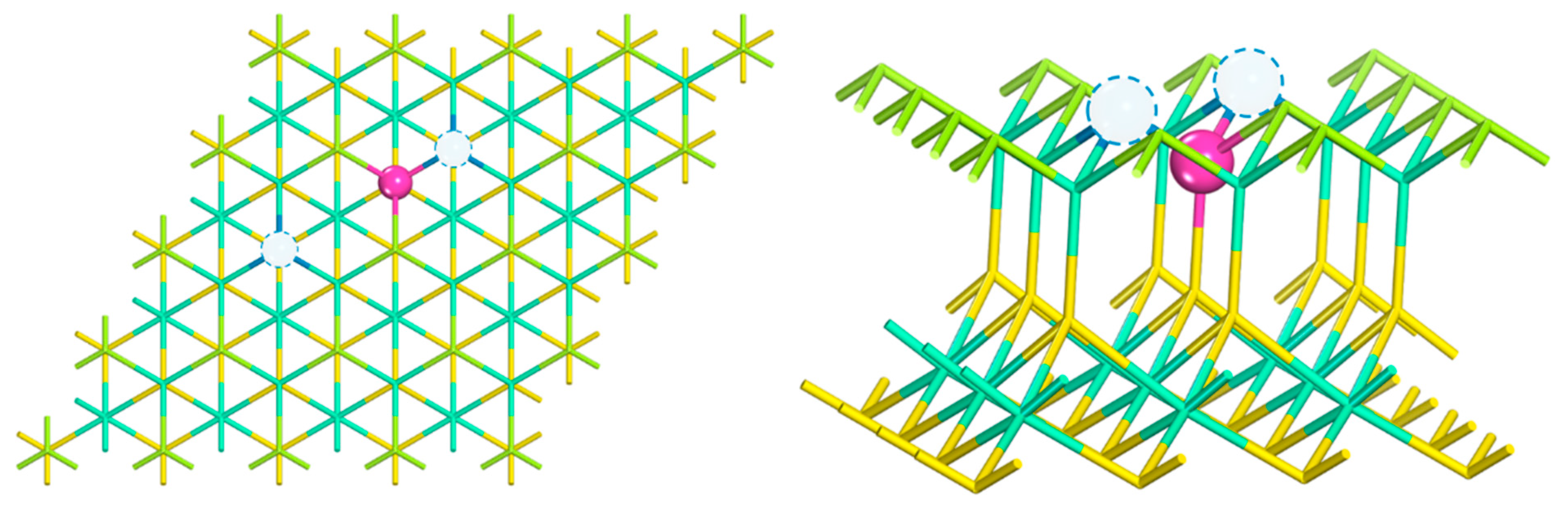
2.1.1. Crystal Structure

In the previous study [19], the double-vacancy In2S2X (Vd-X, X = Se, Te) model shown in Figure 1 is stable by the defect formation energy ( E f ). Vd-X has excellent photocatalytic properties, e.g., high light absorption coefficiency, suitable band edge position, and high CO2 reduction to HCHO selectivity. Vd-X exhibits good thermodynamic stability due to small total energy and temperature fluctuations in molecular dynamics simulations at 300 K, as shown in Figure S1. On this base, we further doped the fourth-period (Sc–Ni) and fifth-period (Y–Mo, Ru–Pd) transition metals at the positions of In atoms exposed by the central vacancy, as shown in the positions marked by pink atoms in Figure 1. The defect formation energies of dopant atoms are shown in Figure S2. The negative defect formation energies of all doped atoms indicate that they are stable.

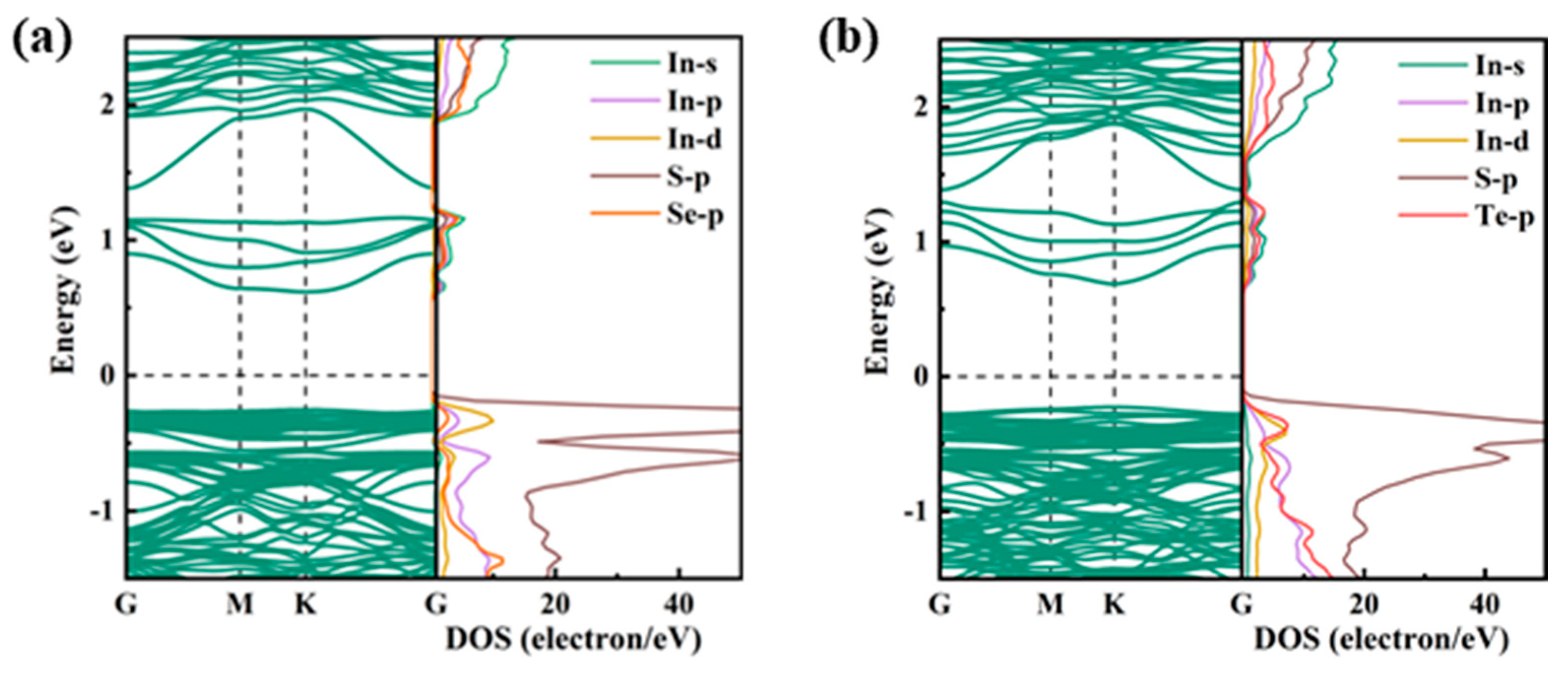
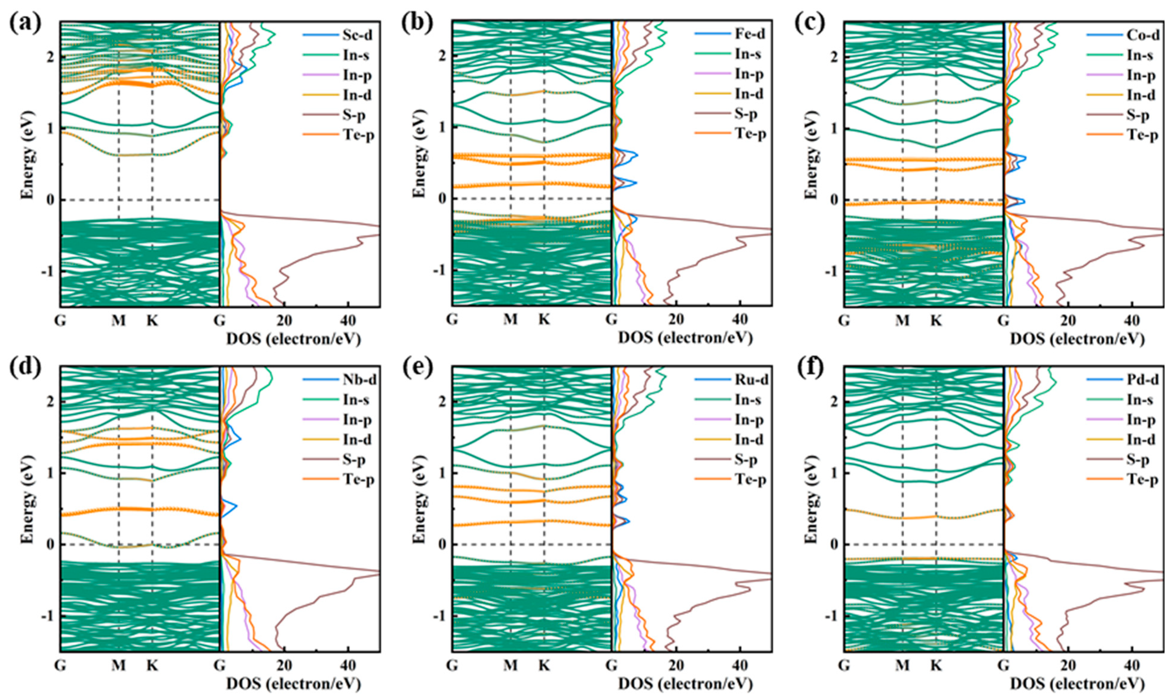
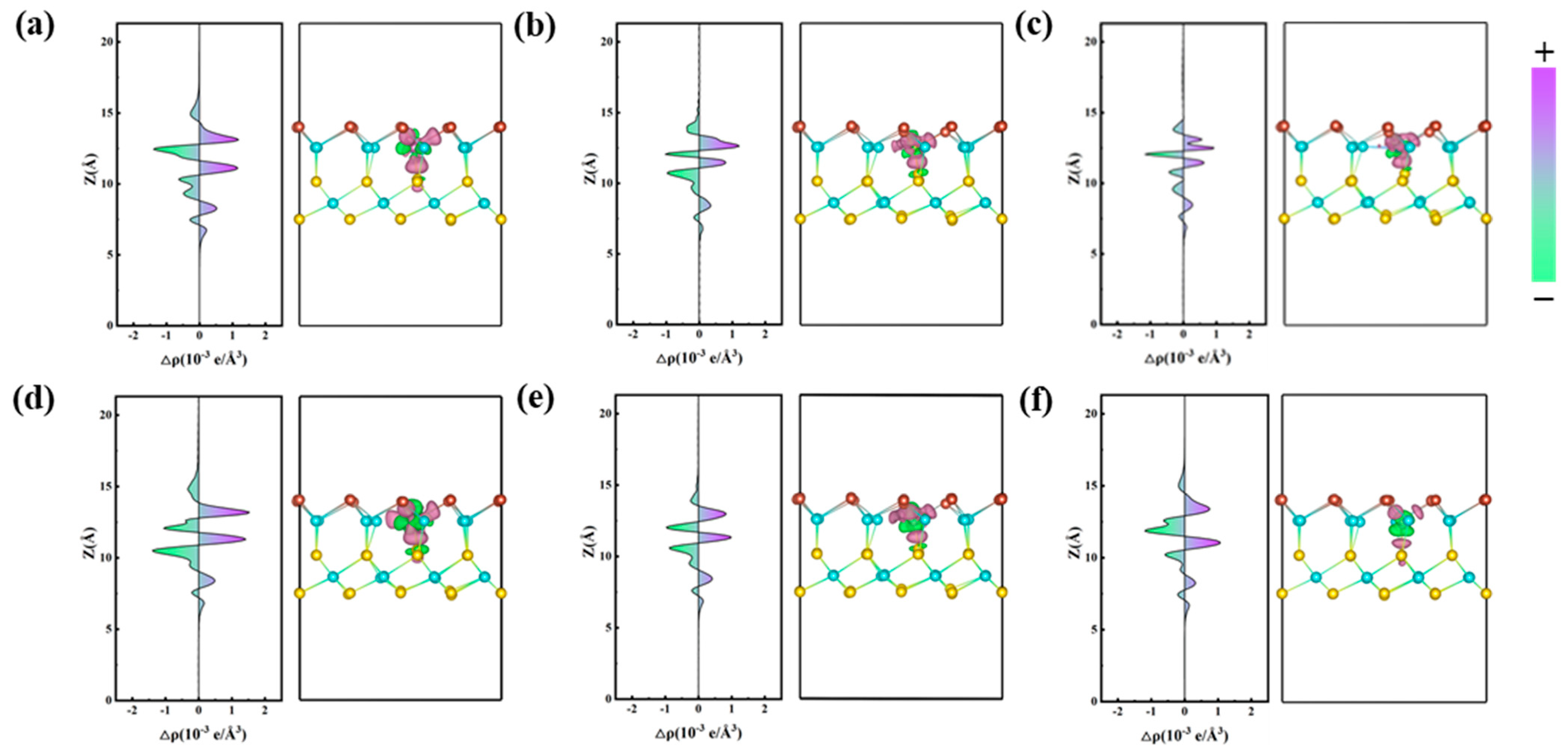
2.1.2. Electronic Properties

The band structure and PDOS of Vd-X are shown in Figure 2. The double-vacancy defect induces four gap bands between the conduction and valence bands. It can be found from PDOS that the gap bands are mainly contributed by the s orbital of In atom and the p orbital of X atom. The gap bands largely reduce the intrinsic bandgap of In2S2X, thereby enhancing the light absorption of visible and near-infrared light, which has been demonstrated in previous studies [19].
Figure 3 shows the band structure and PDOS of M@Se (M = Sc, Mn, Ni, Nb, Mo, Pd), those for others are shown in Figure S3 in the Supporting Information. The contribution of dopant atoms in the energy band mainly comes from their d orbitals, indicated by orange bubbles. The area with dense bubbles indicates that the d-orbital contribution of dopant atoms is greater, while the sparse means small contribution. Importantly, the position of the energy bands contributed by the M-d orbitals can be classified according to the different type of the dopant atom, i.e., the contribution of d0 atoms is mainly between the conduction band and gap band caused by vacancy defects; d0–5 atoms fall into mainly the gap band region; while d5–10 is mainly between the gap band and valence band.
For M@Te, the band structure and PDOS for M = Sc, Fe, Co, Nb, Ru, Pd are shown in Figure 4a–f, those for others are given in the Supporting Information Figure S4. We can find the d-orbital contribution of dopant atoms show similar “type”-dependence as that of M@Se. The same metal atom doping has similar electronic properties in M@Se and M@Te, e.g., there are rich gap bands, but it can be found from PDOS that their effects would be different due to their different position. Therefore, different surfaces with the similar bimetallic active sites would have different light absorption capacities and redox properties.
In order to observe the interaction between dopant atoms and Vd-Se, the average charge density difference and three-dimensional differential charge in the x-y plane between dopant atoms and Vd-Se were calculated, as shown in Figure 5, where positive values (purple area) indicate electron accumulation and negative values (green area) indicate electron consumption. Those for others are shown in Figure S5. Electrons are transferred in the region of the doped atoms. The dopant atoms mainly lose electrons, the Se atoms on the surface, and the S atoms in the middle of the system gain electrons. By comparing the average charge density difference, it can be seen that the peak values of the average charge density difference corresponding to the dopant atoms are Sc@Se and Nb@Se, Mn@Se and Mo@Se, and Ni@Se and Pd@Se in descending order, which indicates a gradual decrease in electron loss at the dopant atomic sites. The calculation of the bader charge further proves the electronic gains and losses, as shown in Table S1. Among them, Ni atoms (−0.34) and Pd atoms (−0.10) lost the least electrons, while Sc atoms (−1.44) and Nb atoms (−1.29) lost the most electrons. This is mainly due to the electronegativity between dopant atoms and S or Se atoms, as shown in Table S8, the greater the electronegativity difference, the easier it is for metal atoms to lose electrons. The average charge density difference and three-dimensional differential charge in the x-y plane between dopant atoms and Vd-Te are shown in Figure 6, where positive values (purple area) and negative values (green area) represent electron accumulation and consumption, respectively. Those for others doping structures are shown in Figure S6. Like the dopant atoms in Vd-Se, the center of the dopant atoms still loses electrons. However, due to the reduced electronegativity of Te atoms compared with Se atoms, the number of electrons lost by doping atoms is reduced, which may enhance the catalytic activity of active sites. The calculated Bader charge also shows that the doped atoms in Vd-Te can retain more electrons, as shown in Table S1. Co atoms (−0.10) lose the least electrons, but Pd atoms (0.14) gain electrons. Same as the M@Se system, Sc atoms (−1.39) and Nb atoms (−1.17) still lose the most electrons. Among them, the Bader charges of Pd atom (0.14) and Ru atom (0.05) are positive, indicating that the dopant atom is the accumulation area of electrons, so Ru@Te and Pd@Te have better catalytic activity.

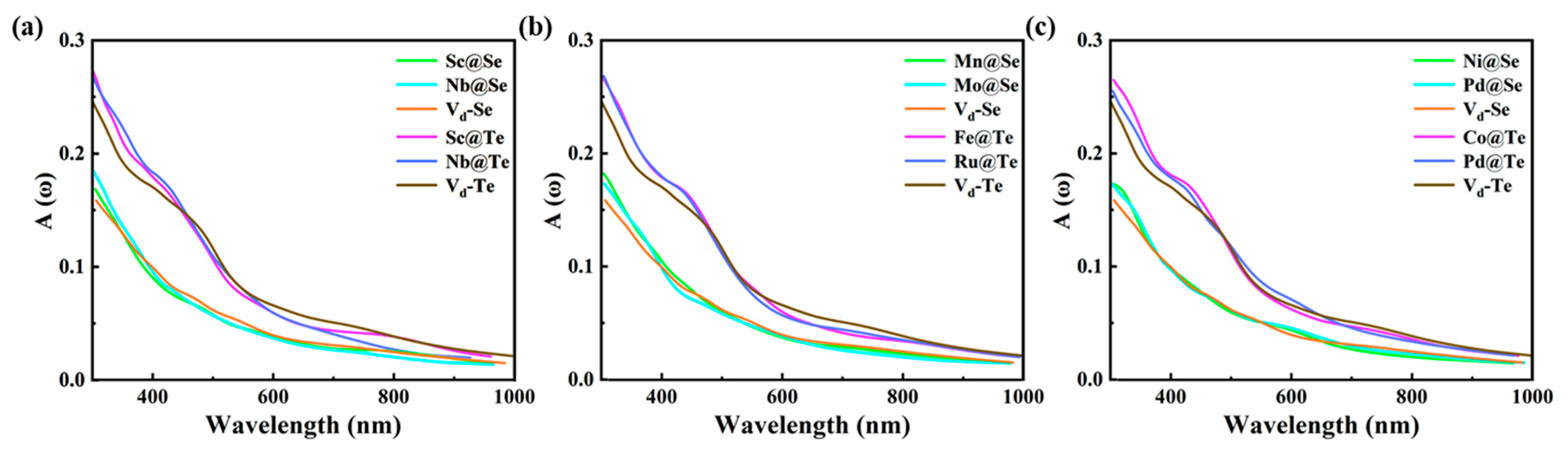
2.1.3. Optical Properties

The absorption spectrums based on PBE and GW + BSE of In2S2Se and In2S2Te unit cell are shown in Figure S7. Compared with the absorption spectrums based on PBE, the absorption spectrums based on GW + BSE are blue-shifted. According to the blue-shift distances, we corrected the absorption spectra calculated by PBE [26], as shown in Figure 7. Compared with Vd-Se, M@Se (M = Sc, Mn, Ni, Nb, Mo, Pd) mainly enhances the absorption of near-ultraviolet light. Compared with Vd-Te, M@Te (M = Sc, Fe, Co, Nb, Ru, Pd) mainly enhances the absorption of near-ultraviolet and visible light in the range of 300~500 nm.

2.2. Photocatalytic Performance of M@X

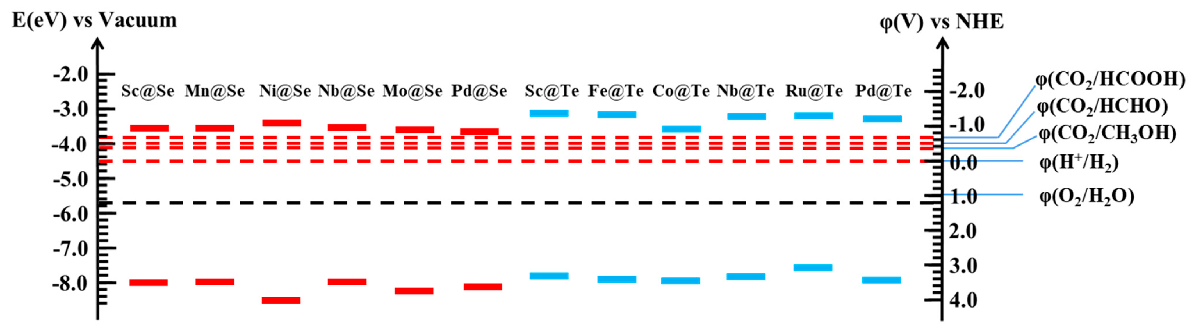
2.2.1. Edge Potential

Appropriate band edge potential is also one of the necessary characteristics of photocatalysts. The band edge potential of Sc@Se, Mn@Se, Ni@Se, Nb@Se, Mo@Se, Pd@Se and Sc@Te, Fe@Te, Co@Te, Nb@Te, Ru@Te, Pd@Te is shown in Figure 8. The band-edge potentials of the others are shown in Figure S8 and Figure S9, respectively. Since Janus In2S2X has intrinsic polarization, the electrostatic potential difference is considered when calculating the band edge potential. It can be found that all photocatalysts satisfy the basic potential requirements for CO2 reduction. On the whole, the CBM of Vd-Te has a higher potential, and it has a stronger reducing ability from a thermodynamic point of view.

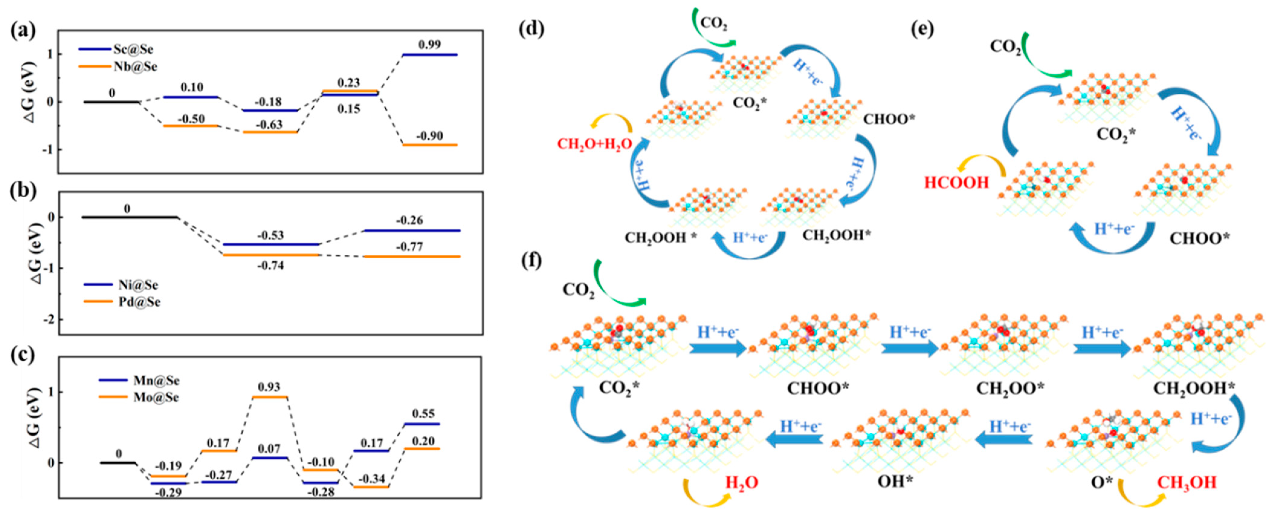
2.2.2. Photocatalytic Performance of M@X for CO2 Reduction

In order to deeply explore the influence of dopant atoms on the photocatalytic performance, the reaction pathway and free energy change of CO2 reduction are calculated. The essential reason for the effect of dopant atoms on catalytic performance is revealed according to the control steps, as shown in Table 1 and Table 2. The electronic interactions between metal sites and reactants are closely related to the interactions and d-band centers of metal atoms, so the d-band centers of dopant atoms in M@X (M = Sc–Ni, Y–Mo, Ru–Pd) are shown in Figure 9.
I
Photocatalytic performance of M@Se
Different doping atoms make the Vd-Se have different active sites, so the adsorption and activation effects of CO2 are different, which directly leads to different effects of photocatalyst on the reaction path, product selectivity, and reaction ability of CO2 reduction. Their free energy changes are further analyzed and compared. (1) M@Se (M = Sc, Ti, V, Y, Zr, Nb) with dopant atoms (d0), whose d-band center is far from the Fermi level and is positive, can reduce CO2 to CH2O (shown in Figure 9). Among them, the free energy changes and reaction pathways on Sc@Se and Nb@Se surfaces are shown in Figure 10a,d, respectively. The free energy change of others is shown in Figure S10a. (2) M@Se (M = Co, Ni, Rh, Pd) with dopant atoms (d5–10), whose d-band center is negative, can reduce CO2 to HCOOH (shown in Figure 9). The free energy changes and reaction pathways on Ni@Se and Pd@Se surfaces are shown in Figure 10b,e, respectively. The free energy change of others is shown in Figure S10b. (3) M@Se (M = Cr, Mn, Fe, Mo, Ru) with dopant atoms (d0–5), whose d-band center is close to the Fermi level, can reduce CO2 to CH3OH (shown in Figure 9). The free energy changes and reaction pathways on Mn@Se and Mo@Se surfaces are shown in Figure 10c,f, respectively. The free energy change of others is shown in Figure S10c.
CO2→CH2O: The CO2 is selectively reduced to CH2O on the Sc@Se and Nb@Se surfaces, which is consistent with that on the Vd-Se surface, and the reaction pathway is also the same, as shown in Figure 10d. But the catalytic performance of different active sites is different (shown in Figure 10a). The fourth hydrogenation reaction is the rate-determining step obviously, due to the largest difference in free energy change in this step (Figure 10a and Figure S10a). In the fourth hydrogenation reaction, the CH2OOH* intermediate adsorbed a hydrogen atom and desorbed one CH2O molecule and one H2O molecule. The structure of the intermediate after the third hydrogenation reaction is shown in Figure S11, where O-In, O-M (M = Sc, Ti, V, Y, Zr, Nb), and O-C bond lengths are shown in Table S2. Furthermore, we analyzed interactions between intermediates and photocatalysts. It can be found that in Sc@Se, Ti@Se, and V@Se, the O1-In1 (2.30 Å) and O-In2 (2.45 Å) bonds on the surface of Sc@Se are longer than that on Ti@Se and V@Se surface. While on Y@Se, Zr@Se, and Nb@Se surface, the O1-In1 (2.50 Å) and O-Nb (2.49 Å) bonds on Nb@Se are longer than those of Y@Se and Zr@Se. As the bond length is longer, the interaction between atoms is weaker, so the smaller the energy required for chemical bond breaking, the easier the hydrogenation reaction occurs. Therefore, in M@Se (M = Sc, Ti, V, Y, Zr, Nb), the Sc@Se and Nb@Se surfaces have higher catalytic performance for this reaction. The fourth hydrogenation reaction is an endothermic reaction on the surface of Sc@Se (0.84 eV), while it is an exothermic reaction on the surface of Nb@Se (−1.13 eV), and the free energy decreases. Therefore, the reduction of CO2 to CH2O tends to proceed on the Nb@Se surface.
CO2→HCOOH: CO2 molecules are selectively reduced to HCOOH on the surface of Ni@Se and Pd@Se, and the reaction step of selective change is the second hydrogenation reaction, as shown in Figure 10b. In the second hydrogenation reaction, H is adsorbed on the O atoms to generate HCOOH molecules on the Ni@Se and Pd@Se surfaces, while CO2 is reduced to CH2OO* intermediates on the Vd-Se surface. The structure of the intermediate after the first hydrogenation reaction is shown in Figure S12. Compared with Co@Se and Rh@Se, Ni@Se and Pd@Se have a smaller free energy rise in the second hydrogenation reaction, which is beneficial to the reaction. This is mainly because the d-band centers of Ni atoms and Pd atoms in Ni@Se and Pd@Se are negative and farther away from the Fermi level and, thus, more inclined to generate and desorb HCOOH. On the other hand, due to the small atomic radii of Co, Ni, Rh, and Pd, they do not act on the CHOO* intermediate after doping into Vd-Se, so the electron transfer is reduced, and CO2 can only be reduced to HCOOH through a two-electron process. The second hydrogenation reaction is an endothermic reaction on the Ni@Se surface (0.27 eV), while it is an exothermic reaction on the Pd@Se surface (−0.03 eV), and the free energy decreases. Therefore, the reduction of CO2 to HCOOH is more favorable on the Pd@Se surface.
CO2→CH3OH: CO2 molecules are selectively reduced to CH3OH on the surface of Mn@Se and Mo@Se. The reduction selectivity is different from the Vd-Se surface, which is mainly reflected in the fourth hydrogenation reaction. In this step, H is adsorbed on C on the surface of Mn@Se and Mo@Se to react to generate CH3OH molecule and O* intermediate, while CO2 is reduced to a HCHO and H2O molecule on the surface of Vd-Se surface. The second hydrogenation reaction is the controlling step due to the free energy change. The structures of the intermediates after the first hydrogenation reaction on the Mo@Se and Mn@Se surfaces are shown in Figure S13b,d, where the distances between the reaction intermediates and the surface are shown in Table S3. The C-Mn bond (2.58 Å) is longer than the C-Mo bond (2.12 Å), and the interaction between C atoms and Mn atoms is weaker than that between C and Mo atoms, so it is easier to add hydrogen on the C atoms of Mn@Se surface. Thus, the reduction of CO2 to CH3OH tends to proceed on the surface of Mn@Se. While in Mo@Se and Ru@Se, the C-Mo bond (2.12 Å) on the Mo@Se surface is longer than the O2-Mo bond (2.05 Å), while the C-Ru bond (2.11 Å) on the Ru@Se surface is shorter than the O2-Ru bond (2.16 Å). Therefore, the interaction between C and Mo atoms on the Mo@Se surface is weaker than that between O and Mo atoms, which is more favorable for the adsorption of H on C atoms. The free energy change in the second hydrogenation reaction on the Mo@Se surface is less than that on the Ru@Se surface. Therefore, the free energy change of the Mn@Se (0.02 eV) surface is smaller than that of Mo@Se (0.36 eV), as shown in Figure 10c.
II
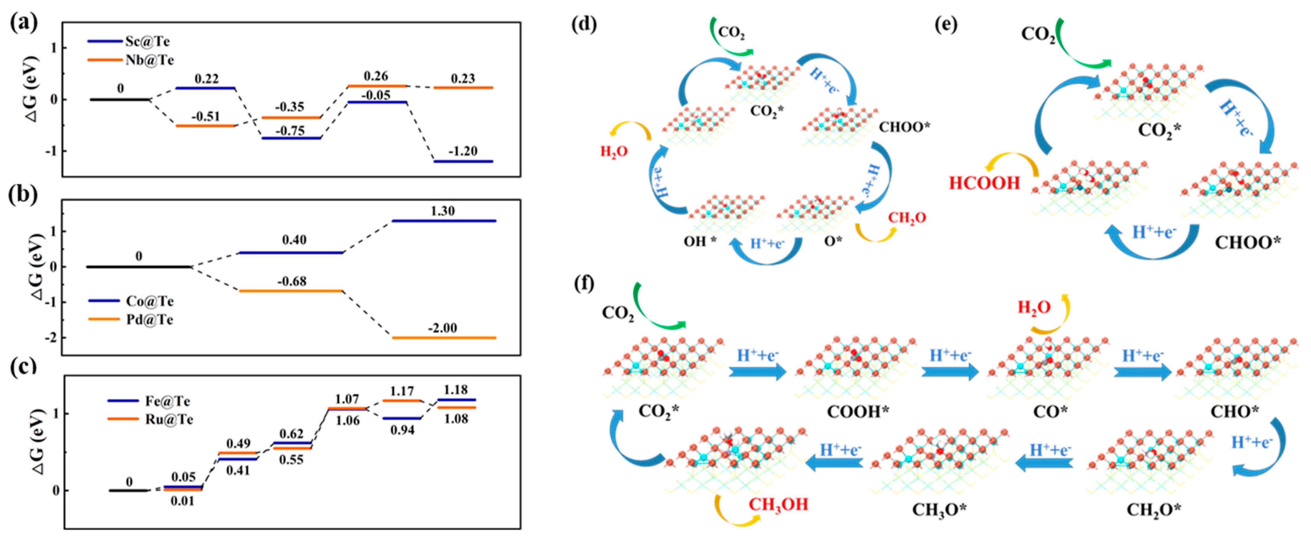
Photocatalytic performance of M@Te
The M@Te systems have the same product selectivity with M@Se systems due to the similarity metal sites in structures and can also reduce CO2 to CH2O, CH3OH, and HCOOH, respectively. (1) M@Te (M = Sc, Ti, V, Y, Zr, Nb) with dopant atoms (d0) whose d-band center is far from the Fermi level and is positive and can reduce CO2 to CH2O (shown in Figure 9). The free energy changes and reduction pathways on Sc@Te and Nb@Te surfaces are shown in Figure 11a,d. The free energy change of others is shown in Figure S14a. (2) M@Te (M = Co, Ni, Rh, Pd) with dopant atoms (d5–10) whose d-band center is far from the Fermi level and is negative and can reduce CO2 to HCOOH (shown in Figure 9). The free energy changes and reaction pathways on Co@Te and Pd@Te surfaces are shown in Figure 11b,e, respectively. The free energy change of others is shown in Figure S14b. (3) M@Te (M = Cr, Mn, Fe, Mo, Ru) with dopant atoms (d0–5) whose d-band center is close to the Fermi level can reduce CO2 to CH3OH (shown in Figure 9). The free energy changes and reaction pathways on Fe@Te and Ru@Te surfaces are shown in Figure 11c,f, respectively. The free energy change of others is shown in Figure S14c. However, M@Te has different effects on the reaction pathway and catalytic activity of CO2 reduction. Their free energy changes are further analyzed and compared.
CO2→CH2O: CO2 molecules are selectively reduced to CH2O on Sc@Te and Nb@Te surfaces, but the reaction pathways are different. The reaction path of CO2 on the surface of Nb@Te is the same as that of Vd-Te (as shown in Figure 11d), but the reaction path of CO2 on the surface of Sc@Te is the same as that of Sc@Se (as shown in Figure 10d). The second hydrogenation reaction has very important influence on the whole reaction path (as shown in Figure 11d). The structure of the intermediate after the first hydrogenation reaction is shown in Figure S15. It can be found that different active sites interact differently with reaction intermediates. The CHOO* reaction intermediate forms two O-In bonds and one Sc-O bond on the Sc@Te surface, but only one Nb-O bond on the Nb@Te surface. Therefore, during the second hydrogenation step, CHOO* reacts on the surface of Sc@Te to generate CH2OO* intermediate but desorbs on the surface of Nb@Te to form a CH2O molecule and O* intermediate. The fourth hydrogenation reaction is the controlling step for the reduction of CO2 to CH2O due to the free energy change. The structure of the intermediate after the third hydrogenation reaction is shown in Figure S16, where O-In, O-M (M = Sc, Ti, V, Y, Zr, Nb), and O-C bond lengths are shown in Table S4. We further analyzed the interactions between intermediates and photocatalysts. It can be found that in Sc@Te, Ti@Te, and V@Te, the O1-In1 (2.38 Å) and O-In2 (2.27 Å) bonds on the surface of Sc@Te are longer compared with Ti@Te and V@Te, so it is more conducive to desorb CH2O and H2O molecules in the fourth hydrogenation reaction. In Y@Te, Zr@Te, and Nb@Te, there is only one Nb-O bond (1.93 Å) on the surface of Nb@Te, which is more reactive in the fourth hydrogenation reaction. As shown in Figure 11a, Sc@Te is more advantageous in the process of selective reduction of CO2 to CH2O, because the free energy change of Sc@Te (−1.15 eV) in the fourth hydrogenation reaction is larger than that of Nb@Te (−0.03 eV).
CO2→HCOOH: CO2 molecules are also selectively reduced to HCOOH on the Co@Te and Pd@Te surfaces, and the CO2 reduction pathway is the same as that of M@Se. The free energy change is shown in Figure 11b.The second hydrogenation reaction is the rate-determining step. The structures of the intermediate after the first hydrogenation reaction are shown in Figure S17; here, O-In, O-M (M = Co, Ni, Rh, Pd) and O-C bond lengths are shown in Table S5. Among them, Pd and Co do not act on the CHOO* intermediate, which also makes it easier for H atoms to adsorb on the O atom in the second hydrogenation reaction to form HCOOH. The other main reason might be that the d-band centers of Co atoms and Pd atoms in Co@Te and Pd@Te are negative and farther away from the Fermi level, so they are more inclined to generate and adsorb HCOOH. In the second step, the hydrogenation reaction is an endothermic reaction on the Co@Te surface (0.90 eV), while it is an exothermic reaction on the Pd@Te surface (−1.32 eV). Therefore, the reduction reaction of CO2 to HCOOH tends to take place on the Pd@Te surface.
CO2→CH3OH: CO2 molecules are selectively reduced to CH3OH on the surface of Fe@Te and Ru@Te, but the reaction pathway is different from that of M@Se. As shown in Figure 11f, on the Fe@Te and Ru@Te surfaces, H atoms are preferentially adsorbed on C atoms rather than O atoms, thus desorbing a H2O molecule first and then a CH3OH molecule. The different activation of CO2 due to the influence of surface atoms have a very important effect on the reaction pathway. Therefore, the structure and the bonds length after CO2 adsorption is analyzed, as shown in Figure S18 and Table S6. The bonds length of C-Fe bonds and C-Ru bonds are shorter than C-In3 bonds, so the interaction between C atoms and Fe or Ru is stronger than that between In3 atoms, so H atoms are more inclined to adsorb on O1 atoms (in the O1-C bond) firstly. The third hydrogenation reaction is the controlling step for the reduction of CO2 to CH3OH due to the interaction between intermediates CO* and photocatalyst surfaces. The Bader charges of the doped atoms after the second hydrogenation reaction is studied, as shown in Table S7. Fe@Te has more Bader charges than Cr@Te and Mn@Te. Similarly, Ru@Te also has more Bader charges than Mo@Te. Therefore, the interaction between intermediate CO* and Fe/Ru atoms are stronger, and electrons on the Fe and Ru atoms are more likely to transition to the reaction intermediates, reducing the reaction free energy and improving the photocatalytic performance. In the third hydrogenation reaction, the free energy change of Ru@Te (0.06 eV) is smaller than that of the Fe@Te (0.21 eV) surface (as shown in Figure 11c). Therefore, the reduction of CO2 to CH3OH tends to proceed on the Ru@Te surface.

3. Computational Details

All density functional theory (DFT) calculations were performed using Vienna ab initio simulation package (VASP6.2.1) [27,28]. The Perdew–Burke–Ernzerh (PBE) function in the generalized gradient approximation (GGA) is applied to describe electron interactions and related energies [29,30]. Electron–ion interactions in periodic systems are addressed using the frozen-core projector augmented wave (PAW) method [31]. Plane wave cut-off energy is selected as 450 eV. The convergence criteria for the energy and force of each atom were set to 10−5 eV and 0.01 eV/Å, respectively. A vacuum layer of 15 Å was set to avoid the interaction between the periodic systems. Van der Waals correction was performed using the DFT-D3 method [32]. The unit cell and supercell systems use 15 × 15 × 1 and 3 × 3 × 1 k-mesh for structure optimization and total energy calculation, respectively [33]. Using water as the solvent, Gibbs free energy calculations were performed in the VASP6.2.1sol package to take solvent effects into account [34,35]. In order to predict more accurate optical properties, we use the GW [36,37] + BSE [38,39,40] method to obtain the absorption spectrum of the unit cells.
To evaluate the light absorption properties, we calculated the optical absorbance A(ω) as follows [41]:
A ω = ε 2 L ω / c
ε2 are the imaginary parts of the complex dielectric function ε(ω). L is the thickness of the vacuum layer, 15 Å, and c is the speed of light in vacuum. ω is the angular frequency of light, and the conversion relationship with the wavelength (λ) is ω = 2π/λ.
The defect vacancy formation energy (Ef) represents the energy required for metal atoms to be doped into the system, and the calculation formula is as follows [42]:
E f = E ( d o p e d ) E p e r f e c t + μ I n μ A t o m
E(doped) is the energy of the doped system, E(perfect) is the energy of the undoped system, μIn is the chemical potential of the In atom, μatom is the chemical potential of the doped atom, which can be replaced by the energy of isolated atoms in this system.
The band edge potential is calculated as follows [43,44]:
E C B M = Φ + 0.5 E g
E V B M = Φ 0.5 E g
Here, ECBM and EVBM are the band edge potentials at the bottom of the conduction band and top of the valence band compared to the standard hydrogen electrode, respectively. Φ is the work function. Eg is the band gap.
The free energy change ( G ) of hydrogen adsorption during the CO2 reduction process is calculated as follows [45,46]:
G = E + E Z P E T S + e U + G p H
where E is the energy difference in the reaction before and after H adsorption. E Z P E and S are the zero-point energy difference and entropy difference in the reaction intermediates, respectively. T is the room temperature (298.15 K). e is the elementary charge. U is the applied overpotential [47], U = 0 versus reversible hydrogen electrode in this work. G p H is the free energy correction value caused by the change in pH value, G p H = k T m ln 10 × p H [48,49]. Here p H = 7 , T m = 298.15   K , k is the Boltzmann constant.

4. Conclusions

In summary, based on the number of d orbital electrons of the doped metal cations, the dopant atoms are classified into three categories: d0, d0–5, and d5–10. We analyze the impact of various doping atoms on the electronic structure, charge transfer, light absorption, and photocatalytic activity of Vd-X. We elucidate the mechanism of bimetallic active sites on the selectivity of CO2 reduction products through photocatalysis and establish criteria for identifying high-selectivity photocatalysts. The findings demonstrate that dopant atoms with d0, d0–5, and d5–10 contribute to different areas of the band structures: between the conduction and defect-induced gap bands, within the bandgap, and between defect-induced gap bands and valence bands. M@Se primarily boosts the near-ultraviolet light absorption, while M@Te enhances absorption of near-ultraviolet and visible light. Notably, the position of dopant atoms’ d-band centers significantly influences the selectivity of CO2 reduction products. Dopant atoms with positive d-band centers that are farther from the Fermi level exhibit higher selectivity towards HCHO, whereas those with negative d-band centers (d5–10) favor HCOOH. Dopant atoms with d0–5, located closer to the Fermi level, show enhanced selectivity for CH3OH.
Subsequently, we calculate the reaction pathway and the change in free energy for the photocatalytic reduction of CO2 on the M@X (M = Sc–Ni, Y–Mo, Ru–Pd) surface. Consistent selectivity for CO2 products is observed with identical dopant atoms in both M@Se and M@Te. Nb@Se, Mn@Se, and Pd@Se exhibit outstanding photocatalytic activity in converting CO2 to CH2O, CH3OH, and HCOOH, respectively. Within the M@Se system, the fourth hydrogenation reaction acts as the decisive step in the conversion of CO2 to CH2O. Evaluation of the photocatalyst’s catalytic efficiency involves assessing the interaction with the CH2OOH* reaction intermediate. The crucial steps in reducing CO2 to CH3OH and CHOOH occur during the second hydrogenation reaction. A comparison of the interaction between photocatalysts and CHOO* reaction intermediates, as well as the position of the d-band center, forms the foundation for screening photocatalysts. Sc@Te, Ru@Te, and Pd@Te demonstrate outstanding photocatalytic efficacy in converting CO2 to HCHO, CH3OH, and HCOOH, correspondingly. Bader charges of dopant atoms can identify exceptional photocatalysts. This study systematically explored the inherent connection between reactive sites and the selectivity of reduced products, offering valuable theoretical insights for the methodical advancement of highly selective catalysts.

Supplementary Materials

The following supporting information can be downloaded at: https://www.mdpi.com/article/10.3390/catal15060567/s1, File S1: Defect formation energies, band structures and PDOS, the planar-averaged electron density difference Δρ(z) and three-dimensional charge density difference and Bader charges of doping atoms; Absorption spectrum of In2S2Se and In2S2Te unit cell; CO2 adsorption energy and band edge positions; the free energy change of CO2 reduction on the M@X surface, and the structure of the reaction intermediate and some of the bond lengths.

Author Contributions

The manuscript was written through contributions of all authors. Z.C. contributed to investigation, methodology, and writing—original draft. Y.C. contributed to conceptualization and writing—review and editing. W.C. and M.J. contributed to investigation and methodology. H.R., W.Z. and W.G. contributed to conceptualization and investigation. All authors have read and agreed to the published version of the manuscript.

Funding

This work was supported by the National Key Research and Development Program of China (2019YFA0708703), the National Natural Science Foundation of China (U23B2087), the Shandong Provincial Natural Science Foundation of China (ZR2017MB053, ZR2023MB034), the National Key Research and Development Program of China (2019YFA0708703), the Fundamental Research Funds for the Central Universities (20CX06002A), and Taishan Scholars Program of Shandong Province (tsqn201909071).

Data Availability Statement

The original contributions presented in this study are included in the article/Supplementary Materials. Further inquiries can be directed to the corresponding author(s).

Conflicts of Interest

The authors declare that they have no known competing financial interests or personal relationships that could have appeared to influence the work reported in this paper.

References

  1. Li, J.; Huang, H.; Xue, W.; Sun, K.; Song, X.; Wu, C.; Nie, L.; Li, Y.; Liu, C.; Pan, Y.; et al. Author Correction: Self-adaptive dual-metal-site pairs in metal-organic frameworks for selective CO2 photoreduction to CH4. Nat. Catal. 2022, 5, 463. [Google Scholar] [CrossRef]
  2. Wang, J.W.; Ma, F.; Jin, T.; He, P.; Luo, Z.M.; Kupfer, S.; Karnahl, M.; Zhao, F.; Xue, Z.; Jin, T. Homoleptic Al (III) Photosensitizers for Durable CO2 Photoreduction. J. Am. Chem. Soc. 2023, 145, 676–688. [Google Scholar] [CrossRef] [PubMed]
  3. Gong, E.; Ali, S.; Hiragond, C.B.; Kim, H.S.; Powar, N.S.; Kim, D.; Kim, H.; In, S. Solar fuels: Research and development strategies to accelerate photocatalytic CO2 conversion into hydrocarbon fuels. Energy Environ. Sci. 2022, 15, 880–937. [Google Scholar] [CrossRef]
  4. Tian, Y.; Zhang, B.Y.; Chen, J.Y.; Ji, M.X.; Ren, H.; Chi, Y.H. Research on Adjusting Electronic Transport with MoSi2N4/ZrS2(HfS2) II-Type Heterojunction for Photocatalytic Hydrogen Production. Acta Chim. Sinica 2025, 83, 498–509. [Google Scholar] [CrossRef]
  5. Wei, M.J.; Xu, X.Y.; Song, J.Q.; Pan, M.; Su, C.Y.A. 2D layered cobalt-based metal–organic framework for photoreduction of CO2 to syngas with a controllable wide ratio range. J. Mater. Chem. A 2023, 11, 691–699. [Google Scholar] [CrossRef]
  6. Wu, Y.H.; Zhang, D.D.; Yin, H.Y.; Chen, Z.N.; Zhao, W.; Chi, Y.H. Density Functional Theory Study of Janus In2S3X Photocatalytic Reduction of CO2 under “Double Carbon” Target. Acta Chim. Sinica 2023, 81, 1148–1156. [Google Scholar] [CrossRef]
  7. Jiang, D.; Song, Q.; Xu, Y.; Li, D. Photo-and Electro-Catalytic Processes: Water Splitting, N2 Fixing, CO2 Reduction; John Wiley & Sons: Hoboken, NJ, USA, 2022; ISBN 978-3-527-83007-7. [Google Scholar]
  8. Jiang, W.; Liu, W.; Wang, Y.; Zhao, Z.; Li, Q.; Wu, Y.; Liu, T.; Xie, H. Electrochemically Regenerated Amine for CO2 Capture Driven by a Proton-Coupled Electron Transfer Reaction. Ind. Eng. Chem. Res. 2022, 61, 13578–13588. [Google Scholar] [CrossRef]
  9. Zhou, Y.; Ye, Q.; Shi, X.; Zhang, Q.; Xie, Z.; Li, D.; Jiang, D. Regulating photocatalytic CO2 reduction selectivity via steering cascade multi-step charge transfer pathways in 1T/2H-WS2/TiO2 heterojuncitons. Chem. Eng. J. 2022, 447, 137485. [Google Scholar] [CrossRef]
  10. Wang, Z.; Shi, Y.; Liu, C.; Kang, Y.; Wu, L. Cu+–Ti3+ interface interaction mediated CO2 coordination model for controlling the selectivity of photocatalytic reduction CO2. Appl. Catal. B Environ. 2022, 301, 120803. [Google Scholar] [CrossRef]
  11. Li, J.; Huang, B.; Guo, Q.; Guo, S.; Peng, Z.; Liu, J.; Tian, Q.; Yang, Y.; Xu, Q.; Liu, Z. Van der Waals heterojunction for selective visible-light-driven photocatalytic CO2 reduction. Appl. Catal. B Environ. 2021, 284, 119733. [Google Scholar] [CrossRef]
  12. Ong, W.J.; Putri, L.K.; Mohamed, A.R. Rational design of carbon-based 2D nanostructures for enhanced photocatalytic CO2 reduction: A dimensionality perspective. Chem.-A Eur. J. 2020, 26, 9710–9748. [Google Scholar] [CrossRef] [PubMed]
  13. Khdary, N.H.; Alayyar, A.S.; Alsarhan, L.M.; Alshihri, S.; Mokhtar, M. Metal oxides as catalyst/supporter for CO2 capture and conversion, review. Catalysts 2022, 12, 300. [Google Scholar] [CrossRef]
  14. Mostafa, M.M.M.; Li, Y.; Halawani, W.; Narasimharao, K.; Salam, M.A.; Alshehri, A.A.; Khdary, N.H.; Al-Faifi, S.; Gu, L.; Chowdhury, A.D. Evaluating the efficacy of nanosized CuZnAl and CuZnZr mixed oxides for electrocatalytic CO2 reduction. Dalton Trans. 2023, 52, 5155–5168. [Google Scholar] [CrossRef] [PubMed]
  15. Di, J.; Chen, C.; Yang, S.Z.; Chen, S.; Duan, M.; Xiong, J.; Zhu, C.; Long, R.; Hao, W.; Chi, Z. Isolated single atom cobalt in Bi3O4Br atomic layers to trigger efficient CO2 photoreduction. Nat. Commun. 2019, 10, 2840. [Google Scholar] [CrossRef]
  16. Xiong, X.; Zhao, Y.; Shi, R.; Yin, W.; Zhao, Y.; Waterhouse, G.I.N.; Zhang, T. Selective photocatalytic CO2 reduction over Zn-based layered double hydroxides containing tri or tetravalent metals. Sci. Bull. 2020, 65, 987–994. [Google Scholar] [CrossRef]
  17. Zhou, Y.; Zhang, Q.; Shi, X.; Song, Q.; Zhou, C.; Jiang, D. Photocatalytic reduction of CO2 into CH4 over Ru-doped TiO2: Synergy of Ru and oxygen vacancies. J. Colloid Interface Sci. 2022, 608, 2809–2819. [Google Scholar] [CrossRef]
  18. Prajapati, P.K.; Malik, A.; Nandal, N.; Pandita, S.; Singh, R.; Bhandari, S.; Saran, S.; Jain, S.L. Morphology controlled Fe and Ni-doped CeO2 nanorods as an excellent heterojunction photocatalyst for CO2 reduction. Appl. Surf. Sci. 2022, 588, 152912. [Google Scholar] [CrossRef]
  19. Chen, Z.N.; Chi, Y.H.; Ma, H.; Yuan, S.; Hao, C.; Ren, H.; Zhao, W.; Zhu, H.Y.; Guo, W. Effect of vacancy concentration on the production selectivity of Janus In2S2X (X = Se, Te) monolayer heterojunction photocatalytic reduction of CO2. Phys. E Low-Dimens. Syst. Nanostruct. 2023, 146, 115549. [Google Scholar] [CrossRef]
  20. Yao, W.; Chen, Y.; Li, J.; Yang, J.; Ren, S.; Liu, W.; Liu, Q. Photocatalytic degradation of methyl orange by Ca doped β-In2S3 with varying Ca concentration. Res. Chem. Intermed. 2022, 48, 1813–1829. [Google Scholar] [CrossRef]
  21. Yang, S.; Xu, C.Y.; Zhang, B.Y.; Yang, L.; Hu, S.P.; Zhen, L. Ca (II) doped β-In2S3 hierarchical structures for photocatalytic hydrogen generation and organic dye degradation under visible light irradiation. J. Colloid Interface Sci. 2017, 491, 230–237. [Google Scholar] [CrossRef]
  22. Feng, J.; Yang, Z.; He, S.; Niu, X.; Zhang, T.; Ding, A.; Liang, H.; Feng, X. Photocatalytic reduction of Uranium (VI) under visible light with Sn-doped In2S3 microspheres. Chemosphere 2018, 212, 114–123. [Google Scholar] [CrossRef] [PubMed]
  23. Tapia, C.; Berglund, S.P.; Friedrich, D.; Dittrich, T.; Bogdanoff, P.; Liu, Y.; Levcenko, S.; Unold, T.; Conesa, J.C.; Lacey, A.L.D. Synthesis and characterization of V-doped β-In2S3 thin films on FTO substrates. J. Phys. Chem. C 2016, 120, 28753–28761. [Google Scholar] [CrossRef]
  24. Wang, L.; Xia, L.; Wu, Y.; Tian, Y. Zr-doped β-In2S3 ultrathin nanoflakes as photoanodes: Enhanced visible-light-driven photoelectrochemical water splitting. ACS Sustain. Chem. Eng. 2016, 4, 2606–2614. [Google Scholar] [CrossRef]
  25. Lin, L.Y.; Yu, J.L.; Cheng, S.Y.; Lu, P.M. Influence of Ag and Sn incorporation in In2S3 thin films. Chin. Phys. B 2015, 24, 078103. [Google Scholar] [CrossRef]
  26. Zhuang, H.L.; Hennig, R.G. Single-layer group-III monochalcogenide photocatalysts for water splitting. Chem. Mater. 2013, 25, 3232–3238. [Google Scholar] [CrossRef]
  27. Kresse, G.; Furthmüller, J. Efficiency of ab-initio total energy calculations for metals and semiconductors using a plane-wave basis set. Comput. Mater. Sci. 1996, 6, 15–50. [Google Scholar] [CrossRef]
  28. Kresse, G.; Hafner, J. Ab initio Molecular Dynamics for Liquid Metals. Phys. Rev. B Condens. Matter Mater. Phys. 1993, 47, 558–561. [Google Scholar] [CrossRef]
  29. White, J.A.; Bird, D.M. Implementation of gradient-corrected exchange-correlation potentials in Car-Parrinello total-energy calculations. Phys. Rev. B 1994, 50, 4954–4957. [Google Scholar] [CrossRef]
  30. Ernzerhof, M.; Scuseria, G.E. Assessment of the Perdew-Burke-Ernzerhof exchange-correlation functional. J. Chem. Phys. 1999, 110, 5029–5036. [Google Scholar] [CrossRef]
  31. Kresse, G.; Joubert, D. From ultrasoft pseudopotentials to the projector augmented-wave method. Phys. Rev. B 1999, 59, 1758–1775. [Google Scholar] [CrossRef]
  32. Grimme, S.; Antony, J.; Ehrlich, S.; Krieg, H. A consistent and accurate ab initio parametrization of density functional dispersion correction (DFT-D) for the 94 elements H-Pu. J. Chem. Phys. 2010, 132, 154104. [Google Scholar] [CrossRef] [PubMed]
  33. Monkhorst, H.J.; Pack, J.D. Special points for Brillouin-zone integrations. Phys. Rev. B 1976, 13, 5188. [Google Scholar] [CrossRef]
  34. Mathew, K.; Sundararaman, R.; Letchworth-Weaver, K.; Arias, T.A.; Hennig, R.G. Implicit solvation model for density-functional study of nanocrystal surfaces and reaction pathways. J. Chem. Phys. 2014, 140, 084106. [Google Scholar] [CrossRef]
  35. Mathew, K.; Kolluru, V.S.C.; Mula, S.; Steinmann, S.N.; Hennig, R.G. Implicit self-consistent electrolyte model in plane-wave density-functional theory. J. Chem. Phys. 2019, 151, 234101. [Google Scholar] [CrossRef]
  36. Bruneval, F.; Vast, N.; Reining, L.; Izquierdo, M.; Sirotti, F.; Barrett, N. Exchange and correlation effects in electronic excitations of Cu2O. Phys. Rev. Lett. 2006, 97, 267601. [Google Scholar] [CrossRef]
  37. Trani, F.; Vidal, J.; Botti, S.; Marques, M.A.L. Band structures of delafossite transparent conductive oxides from a self-consistent GW approach. Phys. Rev. B 2010, 82, 085115. [Google Scholar] [CrossRef]
  38. Albrecht, S.; Reining, L.; Del Sole, R.; Onida, G. Ab initio calculation of excitonic effects in the optical spectra of semiconductors. Phys. Rev. Lett. 1998, 80, 4510–4513. [Google Scholar] [CrossRef]
  39. Onida, G.; Reining, L.; Rubio, A. Electronic excitations: Density-functional versus many-body Green’s-function approaches. Rev. Mod. Phys. 2002, 74, 601–659. [Google Scholar] [CrossRef]
  40. Gruning, M.; Marini, A.; Gonze, X. Exciton-plasmon states in nanoscale materials: Breakdown of the Tamm−Dancoff approximation. Nano Lett. 2009, 9, 2820–2824. [Google Scholar] [CrossRef]
  41. Gajdoš, M.; Hummer, K.; Kresse, G.; Furthmüller, J.; Bechstedt, F. Linear optical properties in the projector-augmented wave methodology. Phys. Rev. B 2006, 73, 045112. [Google Scholar] [CrossRef]
  42. Zhou, W.; Zou, X.; Najmaei, S.; Liu, Z.; Shi, Y.; Kong, J.; Lou, J.; Ajayan, P.M.; Yakobson, B.I.; Idrobo, J.C. Intrinsic structural defects in monolayer molybdenum disulfide. Nano Lett. 2013, 13, 2615–2622. [Google Scholar] [CrossRef] [PubMed]
  43. Sahoo, S.K.; Teixeira, I.F.; Naik, A.; Heske, J.; Cruz, D.; Antonietti, M.; Savateev, A.; Kuhne, T.D. Photocatalytic water splitting reaction catalyzed by ion-exchanged salts of potassium poly (heptazine imide) 2D materials. J. Phys. Chem. C 2021, 125, 13749–13758. [Google Scholar] [CrossRef] [PubMed]
  44. Toroker, M.C.; Kanan, D.K.; Alidoust, N.; Isseroff, L.Y.; Liao, P.; Carter, E.A. First principles scheme to evaluate band edge positions in potential transition metal oxide photocatalysts and photoelectrodes. Phys. Chem. Chem. Phys. 2011, 13, 16644–16654. [Google Scholar] [CrossRef] [PubMed]
  45. Wirth, J.; Neumann, R.; Antonietti, M.; Saalfrank, P. Adsorption and Photocatalytic Splitting of Water on Graphitic Carbon Nitride: A Combined First Principles and Semiempirical Study. Phys. Chem. Chem. Phys. 2014, 16, 15917–15926. [Google Scholar] [CrossRef]
  46. Nørskov, J.K.; Rossmeisl, J.; Logadottir, A.; Lindqvist, L.; Kitchin, J.R.; Bligaard, T.; Jonsson, H. Origin of the overpotential for oxygen reduction at a fuel-cell cathode. J. Phys. Chem. B 2004, 108, 17886–17892. [Google Scholar] [CrossRef]
  47. Li, X.; Sun, Y.; Xu, J.; Shao, Y.; Wu, J.; Xu, X.; Pan, Y.; Ju, H.; Zhu, J.; Xie, Y. Selective visible-light-driven photocatalytic CO2 reduction to CH4 mediated by atomically thin CuIn5S8 layers. Nat. Energy 2019, 4, 690–699. [Google Scholar] [CrossRef]
  48. Rossmeisl, J.; Chan, K.; Skulason, E.; Bjorketun, M.E.; Tripkovic, V. On the pH dependence of electrochemical proton transfer barriers. Catal. Today 2016, 262, 36–40. [Google Scholar] [CrossRef]
  49. Chowdhury, C.; Karmakar, S.; Datta, A. Monolayer group IV–VImonochalcogenides: Low-dimensional materials for photocatalytic water splitting. J. Phys. Chem. C 2017, 121, 7615–7624. [Google Scholar] [CrossRef]
Scheme 1. Photocatalytic CO2 reduction on different M@ In2S2X (X = Se, Te) photocatalysts (carbon: dark gray; oxygen: red; hydrogen: white; indium: turquoise; sulfur: yellow; selenium or tellurium: light green; doped metal: pink).
Catalysts 15 00567 sch001
Figure 1. Top and side views of the Vd-X (X = Se, Te)-doped structure. White dotted spheres indicate the vacancy defects position. The pink spheres indicate transition metal atom doped. Green represent X atoms. Cyan indicates in atoms. Yellow indicates sulfur atoms.
Catalysts 15 00567 g001
Figure 2. Band structure and projected density of states (PDOS) of (a) divacancy In2S2Se (Vd-Se) and (b) divacancy In2S2Te (Vd-Te).
Catalysts 15 00567 g002
Figure 3. The band structures and projected density of states (PDOS) of Sc, Mn, Ni, Nb, Mo, Pd doped Vd-Se are denoted as (a) Sc@Se; (b) Mn@Se; (c) Ni@Se; (d) Nb@Se; (e) Mo@Se; (f) Pd@Se. The contribution of dopant atoms in the band structure is indicated by orange bubbles.
Catalysts 15 00567 g003
Figure 4. The band structures and projected density of states (PDOS) of Sc-, Fe-, Co-, Nb-, Ru-, and Pd-doped Vd-Te are denoted as (a) Sc@Te; (b) Fe@Te; (c) Ni@Te; (d) Nb@Te; (e) Ru@Te; (f) Pd@Te. The contribution of dopant atoms in the band structure is indicated by orange bubbles.
Catalysts 15 00567 g004
Figure 5. The planar-averaged electron density difference Δρ(z) and three-dimensional charge density difference at doping atom positions of (a) Sc@Se; (b) Mn@Se; (c) Ni@Se; (d) Nb@Se; (e) Mo@Se; (f) Pd@Se. The purple and green regions represent positive and negative charges, respectively, with an isovalue of 0.008 e−3.
Catalysts 15 00567 g005
Figure 6. The planar-averaged electron density difference Δρ(z) and three-dimensional charge density difference at doping atom positions of (a) Sc@Te; (b) Fe@Te; (c) Co@Te; (d) Nb@Te; (e) Ru@Te; (f) Pd@Te. The purple and green regions represent positive and negative charges, respectively, with an isovalue of 0.008 e−3.
Catalysts 15 00567 g006
Figure 7. Light absorbance A(ω) of Vd-X and (a) Sc@Se, Nb@Se, Sc@Te and Nb@Te; (b) Mn@Se, Mo@Se, Fe@Te and Ru@Te; (c) Ni@Se, Pd@Se, Co@Te and Pd@Te.
Catalysts 15 00567 g007
Figure 8. Band edge positions of Sc@Se, Mn@Se, Ni@Se, Nb@Se, Mo@Se, Pd@Se and Sc@Te, Fe@Te, Co@Te, Nb@Te, Ru@Te, Pd@Te relative to the vacuum level (left) and the standard hydrogen electrode (right). The black dashed line is the oxygen electrode potential. The red dotted lines from top to bottom are the reduction potential of CO2 reduction to HCOOH, HCHO, and CH3OH, and hydrogen electrode potential, respectively.
Catalysts 15 00567 g008
Figure 9. The d-band centers of dopant atoms in M@X (M = Sc–Ni, Y–Mo, Ru–Pd), the two-color and one-color columns belong to the M@Se and M@Te systems, respectively.
Catalysts 15 00567 g009
Figure 10. Left: (a) Free energy change of CO2 reduction to CH2O on Sc@Se and Nb@Se surfaces; (b) Free energy change of CO2 reduction to HCOOH on Ni@Se and Pd@Se surfaces; (c) Free energy change of CO2 reduction to CH3OH on Mn@Se and Mo@Se surfaces. Right: The reaction pathways for (d) CO2 reduction to CH2O; (e) CO2 reduction to HCOOH; (f) CO2 reduction to CH3OH on doped Vd-Se surface.
Catalysts 15 00567 g010
Figure 11. Left: (a) Free energy change of CO2 reduction to CH2O on Sc@Te and Nb@Te surfaces; (b) Free energy change of CO2 reduction to HCOOH on Co@Te and Pd@Te surfaces; (c) Free energy change of CO2 reduction to CH3OH on Fe@Te and Ru@Te surfaces. Right: The reaction pathways for (d) CO2 reduction to CH2O; (e) CO2 reduction to HCOOH; (f) CO2 reduction to CH3OH on doped Vd-Te surface.
Catalysts 15 00567 g011
Table 1. The control steps and criterion of CO2 reduction on the surface of Vd-Se system.
SlabReduction ProductsControl StepCatalyst Screening
Sc@Se, Ti@Se, V@Se,
Y@Se, Zr@Se, Nb@Se
CH2OThe fourth hydrogenation reactionInteractions between intermediates and photocatalyst surfaces
Cr@Se, Mn@Se, Fe@Se, Mo@Se, Ru@SeCH3OHThe second hydrogenation reactionInteractions between intermediates and photocatalyst surfaces
Co@Se, Ni@Se,
Rh@Se, Pd@Se
HCOOHThe second hydrogenation reactionD-band centers of dopant atoms
Table 2. The control steps and criterion of CO2 reduction on the surface of Vd-Te system.
SlabReduction ProductsControl StepCatalyst Screening
Sc@Te, Ti@Te, V@Te,
Y@Te, Zr@Te, Nb@Te
CH2OThe fourth hydrogenation reactionInteractions between intermediates and photocatalyst surfaces
Cr@Te, Mn@Te, Fe@Te, Mo@Te, Ru@TeCH3OHThe third hydrogenation reactionInteractions between intermediates and photocatalyst surfaces
Co@Te, Ni@Te,
Rh@Te, Pd@Te
HCOOHThe second hydrogenation reactionD-band centers of dopant atoms
Disclaimer/Publisher’s Note: The statements, opinions and data contained in all publications are solely those of the individual author(s) and contributor(s) and not of MDPI and/or the editor(s). MDPI and/or the editor(s) disclaim responsibility for any injury to people or property resulting from any ideas, methods, instructions or products referred to in the content.

