Review

A Review of Coal and Biomass Hydrogasification: Process Layouts, Hydrogasifiers, and Catalysts

Department of Industrial Engineering, University of Salerno, Via Giovanni Paolo II 132, 84084 Fisciano, SA, Italy
*
Author to whom correspondence should be addressed.
Catalysts 2023, 13(2), 417; https://doi.org/10.3390/catal13020417
Submission received: 30 January 2023 / Revised: 13 February 2023 / Accepted: 14 February 2023 / Published: 15 February 2023

Abstract

:
Despite the increasing need for chemicals and energy, the scenario in which fossil feedstocks can be completely replaced by renewables is currently unrealistic. Thus, the combination of biomass and non-renewable matrix-based (i.e., coal) technologies could provide a greener way toward the partial substitution of traditional fuels. The hydrogasification of carbonaceous feedstocks (coal and biomass) for the main production of CH4 offers a promising alternative to this end. However, hydrogasification has received very little attention, and the present review seeks to shed light on the process, reactor, and catalytic advances in the field. Independent of the selected matrices, various efforts have been devoted to the identification of efficient methods for the production of hydrogen feed to the gasifier and energy as well as the reduction in pollutant emissions from the plants. Moreover, the reactor configurations proposed are focused on the intensification of gas-solid contact to reduce by-product formation. The co-hydrogasification of both renewable and non-renewable feedstock is also reviewed, paying attention to the synergistic effect between the two matrices. In addition, due to the slow rates of hydrogasification reaction, the key role of catalysts and feedstock impurities on the reaction kinetics is discussed.

1. Introduction

The transition toward the supplementation or replacement of fossil fuels by means of renewable energy sources passes through the conversion of waste streams [1,2,3] and biomass feedstocks (including sawmill wood wastes, agricultural wastes, and forestry residuals) [4,5,6]. Compared to coal and gasoline refined from oil, methane is able to produce more heat and energy by mass than other hydrocarbons, yielding, at the same time, less carbon dioxide and other pollutants. Thus, the need for natural gas is heightened [7], especially in countries rich in coal sources (such as China [8]). For the above reasons, methane has also replaced coal for power generation in the U.S. [9]. In this scenario, the production of SNG (Substitute Natural Gas) from renewables is a key approach in order to alleviate the intensive demand for methane in many countries [10,11], wherein the produced SNG can be devoted to energy production by combustion or to syngas generation via reforming.
The traditional methods [12] of producing high-calorie gas, mainly containing CH4, from coal involve three steps: gasification and partial oxidation with O2 or steam, Water Gas Shift to reach the desired H2/CO of three, and, finally, methanation [13]. Thus, hydrogasification provides a new viable route for direct CH4 generation from coal. In fact, one of the most promising processes for SNG generation is represented by the hydrogasification of carbonaceous matrices, preferably coming from biomass residuals. However, biomass resources are season-dependent and characterized by a low calorific value, and a scenario in which coal is completely substituted by renewables for power generation is quite unrealistic [14]. Therefore, the identification of processes able to convert biomass and/or coal to fuels is highly desired. In this regard, hydrogasification offers an interesting alternative for the exploitation of coal reserves (widespread and cheap) which, however, requires innovative and clean technologies to reduce the harmful effects of the above fossil fuel.
Generally speaking, hydrogasification occurs in hydrogen-rich environments, starting from coal or other gasifying feedstocks. Figure 1 reports a schematic representation of the typical hydrogasification plant: hydrogen and/or pre-treated biomass are firstly fed to the hydrogasifier reactor, the produced stream is fed to a clean-up unit working at high temperatures for contaminant removal, and, finally, to a methanation reactor for the conversion of the residual carbon monoxide. In the last unit, water removal occurs and the final product (SNG) can be recovered. In particular, the core of the process is represented by the biomass pre-treatment (i.e., hydrolysis, in the case of coal) and hydrogasification (i.e., char hydrogasification, in the case of coal, characterized by a considerably lower reaction rate in comparison to the first step) [15].
The hydrogasification process displays several advantages compared to gasification technology [16]:
  • Lower operative temperatures and higher thermal efficiency (with the minimized contribution of exothermic reactions);
  • Unnecessary expensive oxygen plants typical of gasification units and very low production of harmful chemicals such as PCDDs (polychlorinated diben-zo-p-dioxins) [17];
  • Higher fraction of finally produced methane and lower carbon monoxide yield;
  • Chance of eliminating the residual CO2 through its combination with H2 and further methane production;
  • Higher process compactness (gasification reaction and exothermic pathways occur in the same reactor instead of the two separate reactors of indirect gasifiers).
The use of hydrogen as a gasifier agent gives further advantages: no inert gas is fed into the system, like in the case of air. Thus, it is possible to avoid the production of much-diluted mixtures that are hard to use and can contain nitrogen oxides.
In the work of Steinberg [18], a comparison among different coal gasification technologies was proposed. The data, shown in Table 1, highlight that the hydrogasification process is the most economical. In fact, the latter choice assures an increase of 16% in process efficiency and is shown to be 18% cheaper than the conventional steam-oxygen process. Moreover, the CO2 emissions are reduced to almost 15% with respect to the steam-oxygen process. In addition, although a steam-oxygen process can be practiced underground, based on the ground estimates of this study, hydrogasification underground is still more convenient.
Furthermore, coal hydrogasification was also shown to assure significantly higher CH4 yields with respect to the pyrolysis process [19].
Nevertheless, hydrogasification offers a highly energy-efficient route for the chemical storage of hydrogen, which is very complex in its free form. According to the stoichiometry of the ideal reaction, hydrogasification, in comparison to the gasification process, uses an extra energy input of about 1680 MJ but generates an extra energy output of about 1600 MJ [20]; thus, almost all the energy content of hydrogen can be transferred to methane.
On the contrary, carbon hydrogasification is quite a slow reaction [21,22], becoming the controlling step of the process. In this regard, Zhang et al. [13] reported a carbon conversion of only 50–60% at 850 °C and 7 MPa, with relevant energy consumption and very low economic benefits.
In particular, it was reported that the coal hydrogasification proceeds through three stages [23]: the CH4 yield increases rapidly in the first step, in which the reaction between the active groups of the carbonaceous matrix (-O-CH3,-COOH,-CH2OH,-CH3) and H2 occurs; during the second step, the CH4 yield was found to be constant (in fact, the releasing rate of C-O-(C) and C-O-(H) active groups dominates the CH4 Yield); and in the last step, a slight decrease in methane yield is reported due to the formation of carbon oxides. In particular, the three identified steps involve coal devolatilization and rapid hydrogenation, the secondary reaction of volatile products, and the slow hydrogenation of the residual char, respectively [19]. Moreover, it was found that methane desorption from the carbonaceous matrix surface is the controlling step during coal/biomass homogeneous hydrogasification [24].
To overcome this kinetic behavior of the hydrogasification reaction, the oxidation of the carbonaceous matrix prior to and during hydrogasification has been investigated as a means of enhancing the hydrogasification rate [25]. However, the latter route still requires an expensive oxygen plant.
In particular, during hydrogasification, many factors may influence the carbonaceous matrix reactivity, including char structure, reaction temperature, pressure, and the presence of a catalyst. For example, in the case of homogeneous coal hydrogasification, the reactivity of the system also depends on the applied carbonaceous matrix: in this regard, lignite coal is characterized by the highest reactivity in comparison with hard coal or charcoal [26]. Various authors [27,28] observed a sharp decrease in the hydrogasification reactivity with the increase in the char conversion. For example, Toomajian et al. [29] worked in the range of 600–900 °C and hydrogen pressure up to 3.3 MPa, reporting that the above decline could be due to the strong adsorption of inactive H2, which blocks the active sites and is responsible for the formation of an unreactive surface structure.
As described above, the conversion efficiency of the carbonaceous materials during hydrogasification can be enhanced by increasing the reaction temperature and the hydrogen partial pressure in the reacting mixture. However, char hydrogasification is an endothermic reaction and, from a thermodynamic point of view, high conversions are disadvantaged when the process temperature rises [30].
On the other end, catalyst adoption may assure a significant increase in the reaction rate, leading to mild operative conditions (low temperatures and pressures). Thus, the choice of highly active catalysts is mandatory to assure the desired process efficiency: adequate char conversion and reduced operative costs.
Recently, many reviews have focused on coal/biomass gasification [31,32,33,34,35], while, to the best of our knowledge, very few studies have been focused on reviewing hydrogasification technology. Actually, coal hydrogasification is mainly disadvantaged by the high hydrogen production costs [36]. However, a recent life-cycle assessment on sustainable SNG production from biomass demonstrated that the hydrogasification route assures the lowest acidification potential and global warming potential as well as the lowest cumulative energy demand [37]. Nonetheless, it is clear that the efficiency of hydrogasification is strictly related to the matrix nature, the process layout, and the use of a catalyst. The present review aims to analyze the advances in fuel and chemical production (mainly CH4) from the hydrogasification of both biomass and coal-derived materials (in the case of biomass, the number of scientific studies is lower). Thus, in the following sections, we will review biomass as well as coal hydrogasification by paying attention to the different proposed process layouts, reactor configurations, and chosen catalysts for the two selected matrices.

2. Process Configurations

In this section, the different process layouts and reactor configurations employed for the hydrogasification of coal as well as biomass matrices will be discussed.
In this regard, at the beginning of the present century, Veringa [38] proposed a process for the production of methane-rich mixtures starting from coal or biomass matrices and using H2 coming from an external source for the hydrogasifier feeding. The necessary hydrogen streams were independent of the process for methane production and could be derived through the electrolysis of water, the steam reforming of light hydrocarbons, the partial oxidation of heavy hydrocarbons, or from industrial processes (such as the production of chlorine by means of membrane or diaphragm cells, methanol production, or the production of acetone, isopropanol, or methyl ethyl ketone) or hydrogen from blast furnaces. However, in the subsequent years, close attention has been paid to the hydrogen source and the chance of its direct production within the hydrogasification process. In fact, one of the main obstacles to the industrial development of the hydrogasification processes lies in the necessary identification of alternative sustainable and cheap hydrogen production technologies.

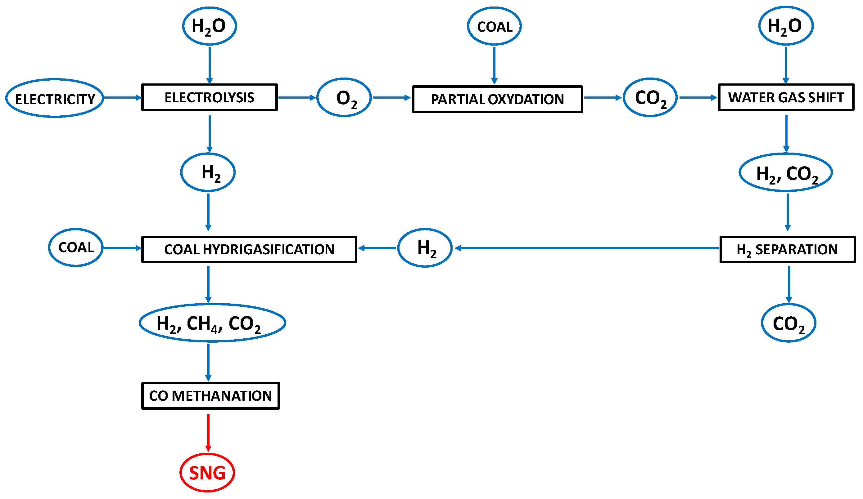
2.1. Process Layouts for the Hydrogasification of Coal-Derived Materials

Coal hydrogasification involves a number of hydrogenation reactions, which can broadly be divided into two classes. One is a faster hydrocracking reaction of volatile matter; another is a slower char-hydrogen reaction. It is known that pressurized hydrogen generally promotes both processes to form methane [39]. In particular, it is known that coal hydrogasification consists of the hydropyrolysis of coal and the hydrogasification of coal char, and the latter process is much slower than hydropyrolysis, which restrains the further conversion of coal (50–60 wt%) even in harsh reaction conditions (900–1100 °C, 5–7 MPa) [40].
Tromp [41] et al. studied the influence of the reacting atmosphere on CH4 generation and found that it was produced primarily by the degradation of the macromolecular structure of coal, the decomposition of the alkyl groups, the polycondensation of semicoke, the secondary reaction of tar, and the hydrogenation of generated free radicals and volatiles. If the raw coal is processed in a hydrogen atmosphere, the introduction of hydrogen will inhibit the polycondensation of free radicals and promote the hydrogenation of coke to generate more CH4. Therefore, the CH4 yield of coal hydrogasification is significantly higher than that of coal pyrolysis. There is also an increase in the yield of CnHm under a hydrogen atmosphere for the same reason. Other carbon-containing gases such as CO2 and CO had lower production rates under a hydrogen atmosphere because the oxygen functional groups in coal will react with hydrogen to form H2O. In particular, the process of coal hydrogasification can be divided into a devolatilization stage, a rapid hydrogenation stage, and a slow hydrogenation stage. The rapid reaction appears to occur between hydrogen and the coal structure of oxygen-containing functional groups, whereas the slow reaction occurs between hydrogen and the residual char [19].
Different countries (the United States, Germany, and Great Britain) started investigating coal hydrogasification in the 1930s [16]. A plant for the hydrogenation of brown coal was able to produce 80–90% methane and ethane in Germany at a rate of 240 tons per day [38]. However, the plant was operated only between 1983 and 1986 due to diminishing economic profits.
In the same years, ENN Group designed a pilot plant using an entrain refraction flow reactor, having a capacity of 50–100 tons of coal per day [42]. Scharf et al. [43] built and operated a semi-technical pilot plant for the hydrogasification of coal in a fluidized bed. Carbon gasification rates up to 82% and methane contents in the dry raw gas (free of N2) of up to 48 vol% were obtained.
The hydrogasification reaction devoted to the production of CH4-rich streams has also been investigated in the framework of the ZEC (Zero Emission Carbon) process [44]. The basic idea is to realize an integrated electric power production system capable of converting approximately 70% of the fuel energy into electricity. No pollutant emissions are expected, and the residual CO2 can be sequestrated through the production of liquid CO2 at 7 Ma. The process layout includes four units: coal hydrogasification, carbonation, calcination, and a fuel cell.
However, due to the unsuccessful commercial scale-up of the above projects, it is clear that several steps forward are still required in the framework of coal hydrogenation. In this regard, various plant configurations have been proposed, where the hydrogen necessary for the hydrogenation was both produced within the process and derived from an external source.
Since the first decades of the 20th century, the hydrogen necessary for hydrogasification was produced from coal itself with an articulation of the gasification process that included partial oxidation and reforming combined with the Water Gas Shift reaction; today, this solution would cause environmental concerns related to the high impact of coal and the non-competitive costs, compared, for example, to the production of hydrogen by methane reforming.
Thus, various researchers have proposed alternative process layouts devoted to increasing the energy efficiency and sustainability of hydrogasification technology.
In this regard, Tosti et al. [36] investigated the feasibility of a coal gasification process employing hydrogen produced via water electrolysis from renewables (wind and solar) during the “off-peak hours” (i.e., by exploiting the surplus of electricity occurring when production exceeds consumption). In particular, they compared the performance of a basic process in which the hydrogen produced via water electrolysis is fed to the hydrogasifier, which is followed by a CO methanation reactor and an innovative WGS (Water Gas Shift-modified configuration, shown in Figure 2.
The simulation study revealed that the WGS-modified process, operated during the renewables shortage, is able to increase energy and exergy efficiency. Thus, they proposed a solution combining the two processes in order to optimize the efficiency according to the wind energy availability: the basic process will be operated during “off-peak” hours while the WGS unit will be activated during a shortage of wind electricity.
A novel hydrogasification plant for the combined storage of renewable energy and the sustainable exploitation of coal sources was proposed [45]: once again, hydrogen was produced via electrolysis. Power was generated through Molten Carbonate Fuel Cells (MCFCs), which allowed for concentrating the CO2 and re-using it for SNG production. The simulation study was carried out for a plant layout including three units: the hydrogasification unit, in which the coal can be gasified (under a H2 atmosphere) to a methane-rich fuel gas stream (syngas); the power unit, in which the fuel syngas is employed for the electric power generation in the MCFC; and the SNG unit, in which the syngas is converted into an SNG stream. This configuration assured a system efficiency higher than 55%, with a reduction in CO2 emissions of more than 100% with respect to the conventional coal-fired power plants and considerable energy saving with respect to the case in which the same energy fluxes are separately generated.
Perdikaris et al. [46] evaluated the feasibility of a coal hydrogasification plant where CO2 is removed through a cyclic CaO-CaCO3 process and electricity is produced with Solid Oxide Fuel Cells (SOFCs). In this layout, the exothermic carbonation reaction between CaO and CO2 provides the heat for a reforming unit, devoted to H2 generation (necessary for both the hydrogasification and fuel cell units). CaO is regenerated within a calcination fluidized bed reactor (heated through the energy produced through the fuel cell), where the released CO2 is compressed and then liquefied at 10 MPa. The simulation study revealed that the power production efficiency was almost 40%, while the CO2 emissions were reduced by almost 90%.
SOFCs were also employed for energy generation in a hydrogasification plant proposed in the work of Yan et al. [14]. Similarly, an Advanced Hydrogasification Process with significantly reduced CO2 emission was developed: hydrogen comes from renewable sources and the co-produced carbon dioxide can be converted to fuel through an algae-based process [47].
Liu et al. [9] carried out a simulation study in which hydrogasification was combined with a sorption-enhanced technique and the advantage of a further methanation or Water Gas Shift shift stage was investigated. The results of modeling (denoted as Case A) demonstrated that the combination of sorption-enhanced hydrogenation with the methanator was able to assure higher CH4 production with a self-sustained H2 supply and near zero CO2 emissions. The quality of the produced Substitute Natural Gas was compared with the results obtained in a commercial coal-to-SNG plant (Great Plains, Case B) in Figure 3. In Case B, the produced methane is slightly lower and the carbon conversion efficiency is significantly reduced (27% against 40% recorded for the sorption-enhanced hydrogasification-methanation plant).
In order to reduce the costs of hydrogen feeding, an alternative to pure hydrogen feeding can be the use of crude gas, which contains H2, CO, CO2, and H2O and is less expensive than the streams commonly used for hydrogasification. In this regard, Feng et al. [48] carried out a preliminary investigation of the influence of CO2 in the feed by adding 10% CO2 to hydrogen during coal hydrogasification over a Co-Ca catalyst at 850 °C and 3 MPa in a fluidized bed reactor. As a result, the CH4 yield (based on the carbon in coal) increased from 77.4% for pure H2 to 188% for the H2-CO2 mixture: in fact, coal hydrogasification and CO2 methanation occurred simultaneously. However, compared to the CO2-free case, the rate of coal gasification was reduced as a consequence of the decreased H2 partial pressure and the competitive adsorption behavior of H2 and CO (a by-product of CO2 methanation) molecules on the cobalt active surface. Similar conclusions were drawn in a work by Gil et al. [22], which investigated the influence of CO2 addition (10%) during the hydrogasification of coal chars at 8 MPa and 700–900 °C (Table 2).
In a very recent work [11], the feasibility of producing a methane-rich stream through the hydrogasification of underground coal (UCG, based on the direct, in situ conversion of the coal seam into process gas) was investigated. UCG has the advantage of higher safety and environmental friendliness with respect to conventional surface gasification. Moreover, it can be applied for the exploitation of dip and thin coal seams (uneconomical for mining) [49]. In particular, a two-stage process was studied: firstly, oxygen was used as a reagent in order to produce the thermal energy necessary in the second stage, in which hydrogen is directly injected over the incandescent coal seam (hydrogasification unit). The results demonstrated that the hydrogasification process is highly stable under the whole sequence of the gasification cycles. Moreover, it was found that the in situ hydrogasification of coal is more effective at higher depths: in fact, the operative pressure increases with the available hydrostatic pressure.
Yasuda et al. [50] proposed a modified hydrogasification process in which coal reacted together with polyethylene mixtures, providing a viable route for the simultaneous exploitation of coal resources and waste plastic materials: the tests were performed in a batch reactor and, for a residence time of 100 s, the carbon conversion to CH4 increased from 57 to 83% upon polyethylene addition [51], and very promising results were obtained even when the polyethylene content was as low as 10%.
Besides the process layout, particular attention has also been paid to the gasifier, which is the core of the hydrogasification process. Between 1970 and 1990, different pilot coal hydrogasifiers were designed, including the four-stage fluidized bed process (IGT-HYGAS) [52], the Rocketdyne hydrogasification process [53], the bituminous coal entrained-flow bed hydrogasifier [41], the Rockwell entrained-flow bed hydrogasifier [54,55], the BG-OG entrained-flow bed hydrogasifier [56], and the ARCH rapid coal hydrogasification process [56]. However, the main drawback of IGT-HYGAS and Rockwell technology was related to the considerable formation of carbon dioxide, while the BG-OG and ARCH gasifiers suffered issues related to the control of the synthesis gas recirculating ratio. As a result, the economic profits of the above pilot plants were not competitive and no commercial demonstration was developed [57]. Thus, researchers’ interest is devoted to the design of new hydrogasifiers, with reduced CO2 production and reduced recycle ratio limitations.
For example, Xia et al. [58] recently designed a pressurized bubbling fluidized bed, in which the pressurization was able to limit the bubbles’ growth. Thus, a large number of small bubbles accumulate in the middle of the bed, enhancing the heat and mass transfer phenomena and resulting in an improved CH4 yield at the expense of carbon dioxide. Zhang et al. [59] investigated the hydrogasification of low-rank coal in a two-stage fixed bed reactor, in which the hydrocracking zone is located in the upper part of the reactor while the particle samples of coke are placed in the lower zone. By changing the hydrocracking temperature, it is possible to modulate the CH4, CO, and CO2 yield of the process. In particular, higher hydrocracking temperatures (up to 700 °C) improved methane selectivity, reducing, at the same time, the rate of carbon monoxide formation.
The performance of a two-stage pressurized fluidized bed (with a continuous flow) coupling a coal catalytic hydropyrolysis (CCHP) zone at low temperature (600 °C) and a coal catalytic hydrogasification (CCHG) zone at high temperature (850 °C) was also investigated [60]. The tar components were released during the hydropyrolysis stage, while methane was mainly formed at the hydrogasification stage. Moreover, the pyrolyzed coal char was subjected to catalytic hydrogasification at a relatively higher temperature during the second stage to increase CH4 formation. Compared to the catalytic hydrogasification reactor alone, this configuration, schematized in Figure 4, despite displaying a slightly lower overall carbon conversion, allowed a simultaneous increase in the methane and high-value-added liquid hydrocarbons (HCL), which can be produced at milder operative conditions with respect to the conventional processes. At the same time, CO and CO2 concentrations were reduced from 3.5 to 1.1% and 2.6 to 1.8%, respectively.
Hüttinger and Michenfelder [61] also carried out the hydrogasification of brown coal in a fluidized bed reactor, observing that the reaction mainly occurred in two stages. In the first stage (up to a few minutes), the hydrogasification rate was very high as a consequence of the pyrolysis and hydropyrolysis reactions of the coal. On the other hand, the lower gasification rates in the second stage were ascribed to the hydrogasification of the residual coke formed in the first stage.
In order to exploit the benefits of fluidized bed reactors (short residence time and good solid-gas contact), avoiding, at the same time, particle agglomeration and defluidization, the performance of an entrained flow bed (operating up to 3 MPa and from 700 to 850 °C) for coal hydrogasification was also investigated [57]. The laboratory apparatus included a facility for high-H2 pressure feeding, a high-temperature tube reactor, a gas-char separation and collection system, a wire mesh filter, a tar cooling and collection system, and support equipment. The selected configuration assured the improvement of methane and light aromatic hydrocarbon yields through the hydrogenation of tar and volatiles, the hydrogasification of coal char, and COx methanation. In particular, the productivity of the above species was enhanced by increasing operating temperature and pressure.
The interest in the employment of entrained-flow reactors for coal hydrogasification was also related to the chance of modeling the carbonaceous particle movement within the reactor, which lay the foundations for an interesting scale-up of laboratory plants [62].

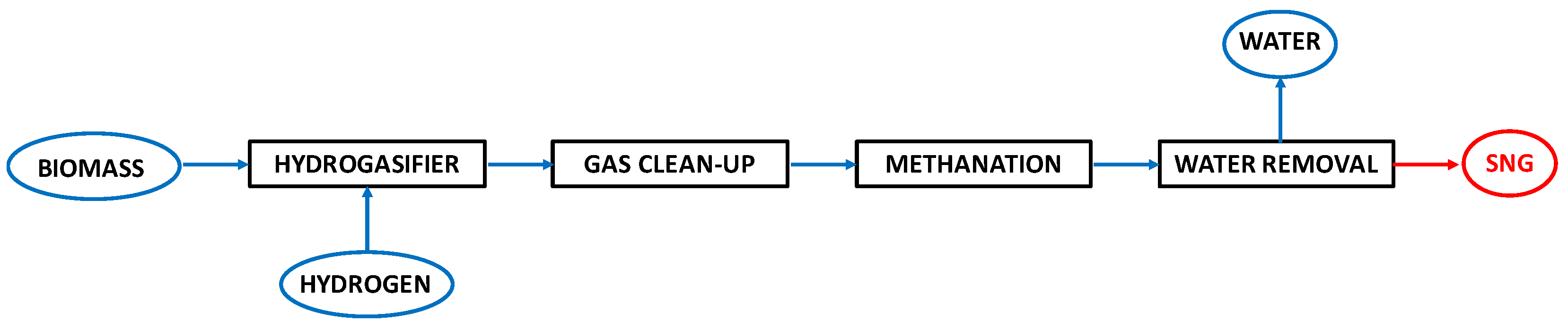
2.2. Process Layouts for the Hydrogasification of Biomass-Derived Materials

Biomass hydrogasification can be seen as a power-to-gas-process for renewable energy storage through the exploitation of hydrogen as an energetic vector [63]. Despite it being a relatively new process, in the early 1980s, Steinberg et al. [64] carried out the hydrogasification of wood by employing an entrained-flow reactor: for pressure ranging from 1.4 to 3.4 MPa and temperatures in the interval 800–1000 °C, carbon conversion exceeded 90%. However, methane formation pathways were preferred only for contact times lower than 1 s.
Thus, also in the case of biomass hydrogasification, various technical issues (mainly related to the economic efficiency of the whole process) still need to be addressed.
As discussed in Section 2.1, the main hurdle to the application of hydrogasification technology is the high price of hydrogen, which negatively influences the economic balance of the entire process. To overcome this problem, a possibility is to produce hydrogen in situ through water electrolysis, steam reforming, or a combination of both. Buceti et al. [65] proposed a system where the hydrogasification of waste-based biomass is coupled with an electrolytic cell: in fact, according to the stoichiometry of the reactions reported in Equations (1) and (2), from two moles of water, it is possible to obtain one mole of pure oxygen and the hydrogen needed for the production of one mole of methane.
H 2 O H 2 + 0.5 O 2
C + 2 H 2 CH 4
The produced oxygen can be further valorized and coupled to oxidation and reformation processes to increase the production of hydrogen and, consequently, the production of methane. In addition, the formed oxygen can be used to oxidize part of the biomass to CO or completely to CO2: thus, produced oxides can then be used in the water-gas shift reaction. The Sabatier pathway can also help to further optimize both the methane yield and the economic efficiency of the whole process.
A similar configuration (shown in Figure 5) was employed for the hydrogasification of refuse-derived fuel (RDF, obtained through mechanical-biological treatments of municipal solid waste) [63].
The simulation study was devoted to identifying the operative conditions that minimize the formation of dioxins, finding that temperatures lower than 600 °C and excess oxygen can avert the generation of such toxic species. The authors also performed an interesting energy analysis: when the plant operates at 300 °C and 3 MPa treating 1 ton∙day−1 of RDF (dry basis) and a corresponding H2 feed of 140 kg∙h−1, the energy content of the produced SNG (8714 kW) is about the same as the power consumed in a water electrolysis unit (8652 kW), while the energy losses of the layout are nearly balanced by the RDF power content (5417 kW) plus the power needed for removing waste heat and for the compressors (433 and 73 kW). As a result, the overall energy efficiency is higher than 60%.
An efficient strategy for the exploitation of both wood by-products and the storage of Variable Energy Resources (VER, i.e., wind and solar, which provide cheap electricity) was proposed, which exploits the biomass hydrogasification process [66]. In particular, three process configurations were investigated: (1) electrolysis + hydrogasification; (2) electrolysis + hydrogasification + partial oxidation + Water Gas Shift; and (3) involving the addition of a Sabatier step in case (2). The simulation study (Figure 6) revealed that both the methane yield and overall energy efficiency were strongly reduced in case (2). The addition of the Sabatier reactor improved the results obtained in case (2); however, the basic case assured the best solution, independent of the electricity cost scenarios selected (electricity supplied any time for the grid or electrolytic system powered by low-cost electricity).
In the same vein, Frigo et al. [67] recently simulated a process for SNG production mainly composed of an electrolyzer, gasifier, and methanator. Depending on the capability of the grid to absorb or not the electric energy produced, the plant can be operated in Mode (A) or (B), respectively. When the grid requires electricity (Mode A), the biomass reacts with the electrolytic oxygen and the produced syngas is sent (with other electrolytic oxygen) to a power unit (along with other electrolytic O2). The power units included an internal combustion engine, a gas turbine, or a high-temperature fuel cell. The exhaust gas (mainly containing CO2 and H2O), after drying, was fed to a methanation process together with electrolytic hydrogen to obtain the SNG. Heat from exhaust gas cooling and from the methanation process was recovered and used to produce additional power. In Mode (B), the biomass is gasified with electrolytic hydrogen to directly produce a CH4-rich gas. After H2O condensation, the gas is fed to a methanation process, in which the almost complete conversion of carbon species to methane occurs. The heat released during the exothermic processes of biomass hydrogasification and methanation could be utilized to generate further power for the electrolyzer supply. The results of the simulation demonstrate that, when the hydrogasifier is operated instead of the gasifier (i.e., the case in which no electricity is required by the grid), it is possible to reach an overall efficiency of 74%.
Similarly, Yan et al. [68] compared the performance of three biomass-based chemical looping processes (A, B, and C). In case (A), the simulated plant involves biomass hydrogasification, methane reforming, and a calcium-based looping system for CO2 adsorption, while cases (B) and (C) consist of a biomass steam gasifier and an iron-looping system with circulation (including the Fe2O3/FeO or Fe3O4/FeO couple, respectively). The highest cold gas efficiency (i.e., the chemical energy of the product SNG gas to energy content in the feedstock) was recorded in the case of the hydrogasification (72%) while values of 54 and 60% were found in cases B and C, respectively. In fact, the thermal efficiency of hydrogasification is expected to be higher compared to steam gasification [69].
Biomass hydrogasification can also be devoted to the synthesis of products other than SNG. In this regard, in the 1990s, the Hynol process, based on the hydrogasification of wood and agricultural residuals or municipal solid waste, was proposed as an alternative economic route for methanol production [70] with reduced CO2 emissions [71]. This process, shown in Figure 7, includes four main units: biomass hydrogasification (carried out in a fluidized bed reactor at 650 °C and 3 MPa), a gas clean-up system for the separation of sulfur or chlorine compounds (whose concentration depends on the selected biomass feedstock), the steam reforming (also called a steam pyrolysis unit) of the produced CH4, and the methanol synthesis of the H2 and CO2 produced during the previous two steps. This layout configuration allows for producing a hydrogen-rich gas which, after CH3OH separation, can be recycled back to the hydrogasifier, thus avoiding the use of expensive oxygen plants as required by commercial steam gasifiers. Moreover, compared to the conventional coal gasification + steam reforming unit, the Hynol process assures an increase in the methanol yield of 13%, with a net reduction in CO2 emission of almost 22%. Finally, a preliminary cost estimation revealed that for a 10,000 tons per day Hynol pant, the production and selling price costs are lower compared to a conventional natural gas steam reforming plant [72].
Sellars [73] proposed a hydro-gasification process in which lignocellulosic biomass is converted into CH4 and light hydrocarbons in a non-oxidative thermochemical process operating with a hydrogen-rich atmosphere at moderate pressures (0.5–5 MPa) and temperatures (400–650 °C). The main idea was to split the hydrogasification step into two units (a fast pyrolysis reactor at low temperatures followed by a catalytic hydrogenation to form a CH4, water, and a hydrocarbon-based stream). The two units are characterized by different residence times (very high in the pyrolyzer) and, in the latter unit, most of the tar compounds are easily converted to form syngas. As a result, the production of depositable tars was very low compared to the conventional gasifiers of lignocellulosic feedstocks.
Concerning the reactor configurations, also in the case of biomass, fluidized beds are preferred [74]. In addition, Han et al. [21] recently investigated the performance of a reactor in which the hydrogasification of wood-based biomass was driven by ball-milling: mechanical movement within the chamber assured close contact between the reacting feedstock and the catalyst at all times. Such a method assured a considerable improvement in the methane formation rate (of almost four orders of magnitude with respect to the conventional thermal process) (Figure 8). In fact, the comminution between the particles (i.e., colliding and sliding) created more reactive carbon species, with a consequent enhancement of the reaction rate. Moreover, the CH4 selectivity was increased (80% of the thermal reactor) to 99.8% (innovative reactor), which was able to operate at a very low temperature (40 °C vs 600 °C).
As described for the coal-fed gasifiers, also in the case of biomass matrices, the hydrogasification of plastic residuals and biomass feedstocks was successfully investigated [75].
Despite very few studies being available on the optimization of the reactor schemes for solely biomass hydrogasification, in some cases, the same configuration was used for both biomass and non-renewable feedstocks. For example, Porada [76] employed the same reactor for the hydrogasification of both basket willow as well as coal matrices, measuring a methane and light hydrocarbon yield considerably higher than the values obtained in the pyrolysis reactor.
Other authors performed hydrogasification studies in the presence of combined coal/biomass feeding [77]. Co-hydrogasification, in fact, has been proposed as a viable route to assure the saving of coal resources while simultaneously making efficient use of biomass reserves. Zhang et al. [78] designed a two-stage fixed bed reactor hosting two different biomass sources (pinewood and rice husk). At 700 °C and 5 MPa, the performance of the reactor fed by the two biomasses was compared with the results recorded by feeding swelling coal and in the co-hydrogasification condition. In the latter case, the synergistic effect between the different kinds of feedstocks increased methane as well as benzene, toluene, and xylene yields, reducing, at the same time, carbon oxide formation. In fact, the presence of small potassium quantities in the biomass probably acted as a catalyst for the coal conversion.
Yan et al. [14] designed a coal/ biomass co-hydrogasification-based chemical looping power generation system, with near zero pollutant emissions. The plant layout is mainly based on a hydrogasifier, a reformer, and a SOFC. Coal and biomass, after drying, can be transported to the hydro-gasifier, where the solid matrices can react with the recycled gasification stream. A downstream cleaning system allowed for feeding purified syngas to the reforming unit: in the reformer, CaO can react with carbon dioxide to simultaneously release heat and shift the reforming equilibrium toward the products. The hydrogen-rich stream was splitted into two flows: the first one is employed for fuel cell feeding while the other one is recycled back to the hydrogasifier (Figure 9).
The combination of the reformer with the chemical looping unit was also an effective strategy to limit the issue of carbon deposition in the fuel cells (which mainly occurs by means of CO disproportion and CH4 cracking pathways). This configuration allowed for obtaining an energy efficiency in the gasifier higher than 99% while the total energy efficiency amounted to 41.2%. Moreover, the carbon capture rate, intended as the fraction of captured carbon with respect to the carbon content of both coal and biomass, was higher than 99%.
Other examples of co-hydrogasification were proposed by Zhu et al. [79], which employed biomass-based additives (sargassum and sawdust and wheat straw char) as catalysts in a coal hydrogasifier (pressurized fixed-bed reactor).
Actually, one of the main obstacles to the industrial development of biomass hydrogasification is related to the huge amount of tar formation, which is difficult to remove from the produced stream and may cause several technical issues during the plant operation [80,81].
The results described above demonstrate that various plant solutions have been proposed for coal/biomass hydrogasification and, in many cases, as alternatives to the direct production of the required hydrogen feed within the hydrogasification plant. However, the major limitation of these solutions is related to the fact that only simulation studies have been conducted and the industrial development of the proposed configurations is still far away.

3. Catalysts for Coal and Biomass Hydrogasification

Due to the very slow kinetics of coal and biomass in the presence of hydrogen, the employment of suitable catalysts for enhancing the reaction rate has been widely investigated [82,83].
In particular, in order to obtain a clear enhancement of hydrogasification kinetics, the catalytic effect of real catalysts as well as of the char/coal impurities were investigated. In the following paragraphs, the catalytic aspects of coal and biomass hydrogasification will be discussed separately.

3.1. Catalytic Hydrogasification of Coal

Due to the very low reactivity of coal, the hydrogasification process requires severe operating conditions (high temperatures of 850–1200 °C and H2 pressures up to 7 MPa,) that cause both considerable energy consumption and safety-related problems. Although high pressures could enhance the CH4 production rate, the transition toward a hydrogasification process under mild conditions is of great interest. In this case, the use of suitable catalysts is crucial to increase the reaction rate [84]. This method is known as coal catalytic hydrogasification (CCHG) [48]. Based on the related literature, the catalysts employed in this process can be split into four categories: iron-group metals-based catalysts, copper and copper-composite catalysts, alkaline- and alkaline-earth-based catalysts, and char-based catalysts.

3.1.1. Iron-Group Metals-Based Catalysts

Several metal catalysts have been studied for CCHG, such as Rh, Ru, Pt, Pd, Fe, Co, and Ni. Although precious metal catalysts have higher activity [85], they are very expensive. Thus, many investigations have been focused on iron-group metals, such as iron, cobalt, and nickel. The results of these studies confirmed the activity of the above species for hydrogasification (Co > Ni > Fe) [86].
Matsumoto et al. [87] observed that the rate of hydrogasification considerably increased by mixing a supported hydrogenation nickel catalyst with the catalyst-loaded char. The author used 0.5 g of a sample char from Australian Yallourn brown coal, characterized by low ash and sulfur content, previously crushed to a 32/60 mesh and subjected to demineralization (using HCl at 80 °C). The wet impregnation method was used to load iron, nickel, and cobalt on demineralized coal by means of an aqueous metal nitrate solution and then heat-treated under an argon stream for 30 min up to 850 °C. In addition, 0.5 g of a commercial catalyst made of 45 wt% of nickel supported on diatomite (Ni/diatomite), crushed to a 150 mesh, was mixed with the catalyzed char. The experiment was performed at atmospheric pressure in a micro-flow quartz tube reactor and a flow rate of 100 mL∙min−1 of H2 was used for the reaction. From the activity tests with 0.8 wt% of metal-loaded and demineralized char, it can be deduced that the catalytic activity decreased in the order Co > Ni > Fe at the reaction temperature of 820 °C. The initial low reactivity was due to poisoning by very small amounts of sulfur contained in the coal and chemisorbed on the catalyst surface. Varying the metal loading, the same authors observed that the catalytic activities were evident with only about 0.1 wt% loading for all the catalysts. However, above 0.2 wt%, the Increase in gasification rate became smaller: in the Fe catalysts case, the curve reached a plateau after showing the highest value at the lowest loading level (under 0.1 wt%). Conversely, with the Co catalyst, the highest activity could be observed over 0.5 wt% of loading. Thus, the highest activity was recorded in the presence of Co, followed by nickel, and then iron. The tests performed with Ni/diatomite mixed with iron-group metal-loaded char showed that this catalytic system increases the hydrogasification rate and also decreases the period of initial low reactivity (i.e., it removes the chemisorbed sulfur from the catalyst surface) (Figure 10). In any case, the catalyst was deactivated at high temperatures and the increase in gasification rate became smaller. From a comparison with the gasification profile without Ni/diatomite, it can be said that the reaction temperature can be decreased by about 200 °C in the presence of Ni/diatomite for cobalt-loaded char (and hydrogasification took place at 570 °C) and by about 150 and 100 °C for iron- and nickel-loaded char, respectively. The profiles of the rate versus catalyst loading are essentially the same as those found in the absence of the Ni/diatomite, so this means that Ni/diatomite increases the activity of iron-group metals without changing the reaction mechanism or catalyst dispersion.
To explain the synergism of Ni/diatomite and the iron-group metal catalysts, the same authors pointed out the catalytic activity of Ni/diatomite, which enhanced the performance even in the case of nickel and removed the sulfur from the catalyst surface: the particles of Ni/diatomite, in fact, are in close contact with the catalyst particles of iron-group metals on the char. Hence, hydrogen atoms dissociated by a supported hydrogenation nickel catalyst can be spilled over toward the catalyst species (Figure 11). It is also possible that hydrogen atoms directly spilled over toward carbon and promote the breaking of C-C bonds.
The iron-group metals are more susceptible to deactivation at high temperatures due to the formation of coke and are prone to deactivation by sulfur poisoning and sintering during hydrogasification [88]. This problem can be overcome with the introduction of a promoter in the catalyst formulation, the most promising of which is represented by the calcium [89], able to modify the catalytic behavior of the iron group, approaching the role of the more expensive Rh or Pt [90]. In addition, Ca retards the sintering of iron-group metals at high temperatures and protects Fe/Co/Ni from sulfur poisoning, preventing, at the same time, sintering phenomena. Yan et al. [91] and Haga et al. [89] showed that the active sequence of the bimetallic catalysts was Co-Ca > Ni-Ca > Fe-Ca in the hydrogasification of bituminous coal, where the superior ability to break the amorphous C-C bonds makes the Co-Ca bimetallic catalyst the higher active. It was considered that a Co-Ca catalyst could promote coal devolatilization, inhibit the graphitization process of coal, and produce active sites on the coal char surface during hydropyrolysis. Many studies have reported that the optimal Ca loading was 1.0 wt% [91,92,93,94].
Yan et al. [40] studied coal hydrogasification in a pressurized fluidized bed reactor with a cobalt-calcium bimetallic catalyst (Co-Ca) prepared by a co-impregnation method. The loading amounts of Co and Ca were 5 wt% and 1 wt%, respectively. The reactor was fed with 50 g of char and the H2 flow rate was 11.7 L∙min−1. The results proved that the catalyst promoted the catalytic depolymerization and hydrogenation of coal during the hydropyrolysis: a considerable increment in carbon conversion was reported, which was enhanced from the 43.4 wt% value of the raw coal-H2 to the 91.3 wt% of the Co-Ca-H2, as well as in methane and tar yields. This trend indicates that only the presence of a Co-Ca catalyst together with H2 is able to break the C-C bonds in the condensed aromatic rings of coal, while their presence alone barely has an effect. The maximum methane formation rate of Co-Ca-H2 is 66.8 mL∙(min∙gcoal)−1, much higher than that measured under pyrolysis conditions (39.2 mL∙(min gcoal)−1). Moreover, the catalyst Co-Ca in H2 reached a CH4 yield of 77.3 wt% in 30 min. The authors deduced that, at a temperature above 800 °C and a pressure of 3 mPa, the main step in the process of Co-Ca-catalyzed coal-char hydrogasification is the breakage of C-C bonds, which is principally caused by the catalytic cleavage promoted by the Co-Ca catalyst: the catalyst, in fact, lowers the activation energy for the C-C breaking step and supplies the hydrogen necessary for the reaction. In addition, the authors pointed out that the hydrogen spillover was not the rate-limiting step. In the reaction mechanism, the first step could be identified as the hydrogenation of small reactive aromatic rings, while the more stable condensed rings were cracked by means of catalytic cleavage, enhanced by the presence of a Co-Ca catalyst in combination with H2.
In a following study [93], the same research group also studied the effect of different amounts of the catalyst Co-Ca on the gross distribution of products, obtaining 90.0 wt% carbon conversion and 77.3 wt% of CH4 yield in 30 min with 5% Co–1% Ca at 850 °C and 3 mPa. An increment in Co loading did not increase the light tar yield (it decreased from 3.60 wt% of 0.75% Co–1% Ca to 2.72 wt% of 5% Co–1% Ca); meanwhile, an increment in Ca loading had the opposite effect. Regarding the heavy tar yield, the catalysts with high amounts of Co and Ca gave the best performance, reaching 1.68 wt% (2.04 times that of raw coal) with a 5% Co–2% Ca catalyst. Once again, the authors attributed these results to the cooperation of Co and Ca in the cracking of C-C in coal’s structure. Due to the short gaseous residence time, heavy volatiles went through a partial secondary catalytic hydrocracking reaction; consequentially, the heavy tar yield increased (yield from 4.09 wt% of raw coal to 4.45 wt% of 5% Co–2% Ca) thanks to the release of polyaromatics. The metallic Ca loading of 1–2 wt% led to a maximum methane formation rate of above 70.0 mL∙(min gcoal)−1.
Therefore, Co-Ca-catalyzed hydrogasification is expected to be a promising process for producing synthetic natural gas from solid fuel. However, the cost of cobalt-based catalysts is one of the key factors in determining the overall process economy [17], which could be preserved by recycling the cobalt catalyst. Feng et al. [94] proposed a HNO3 leaching procedure optimized in two-step precipitation for impurity removal, achieving high activity of the recovered catalyst from the residue of coal hydrogasification: the leaching efficiencies of Co and Ca in each cycle were over 99.7% and 98%, respectively; however, the activity of the recovered catalyst decreased after each leaching cycle due to the increment in impurities in the residue, especially Al impurities, which had a negative effect on Co-Ca activity.
Feng et al. [48] also studied Co-Ca-catalyzed coal hydrogasification using a gas feed of CO2 and H2. The Co-Ca bimetallic catalyst was prepared from cobalt acetate and calcium acetate as precursors of cobalt and calcium, respectively, loaded on 50 g of coal by impregnation. The loading of Co and Ca is denoted as 3 wt% Co–2 wt% Ca. The experiments were conducted in a batch fluidized bed reactor at 850 °C and 3.5 mPa with 12 L∙min−1 flow of pure H2 or H2 + CO2 (10 vol% CO2). The feed gas velocity was three times the minimum fluidization velocity (Umf) of the coal particles. The addition of CO2 increased the yields of the gaseous products and water by 7.4% and 44.7%, respectively, compared to the pure hydrogen atmosphere. In particular, the CH4 yield decreased by 22.6%, while the CO and CO2 yields increased by 24.7% and 6.5%, respectively (Figure 12): the addition of CO2 increased the production of CO and water. It was observed that CO2 and H2 gave the reaction of CO2 methanation, boosting the yields of char and CH4 but not influencing the hydropyrolysis of coal; therefore, the Co-Ca catalyst can catalyze the CO2 methanation, even if the temperature of 850 °C is thermodynamically unfavorable. Regarding the methane formation rate, the H2 + CO2 feed led to a maximum formation rate of 34.6 mL∙(min∙gcoal)−1, lower by about 22.5 mL∙(min gcoal)−1 compared to those in a H2 atmosphere; however, after 40 min, the methane formation rate sharply decreased to zero in pure hydrogen, as coal was the only source of methane, while it stabilized at approximately 23 mL (min∙g∙coal−1) in the presence of CO2.
Yuan et al. [95] performed the Ni-Ca catalyzed hydrogasification of Chinese sub-bituminous coal in a fixed-bed reactor at 750 °C and 1 mPa, using a H2 flow rate of 4.4 L∙min−1. The results exhibited the dependence of product yields on the amount of co-loaded calcium: the use of 5% Ni-1% Ca allowed for the achievement of higher yields of light aromatic hydrocarbons (2.15 wt%, 0.85 wt% of BTX and 0.7 wt% of naphthalene) and gaseous products (51.51 wt% of CH4, CO, CO2, and C2–C3). The calcium addition prevented the metallic nickel from sintering, assisted the dispersion of metallic nickel in coal char, and avoided catalyst poisoning thanks to the reaction with the coal sulfur.
It is well affirmed that cobalt and nickel are the most effective catalysts for coal hydrogasification. However, they are quite expensive, worsening the practice feasibility of the process. Therefore, the use of a cheaper but more highly active catalyst, such as iron, has been investigated.
In the work by Zhang et al. [86], the catalyst that showed the best performance was 5 wt% Fe–1 wt% Ca. The effect on the CH4 yield was noticeable, as it reached 53.4%, while 7.76%, 11.58%, and 12.20% were hit without the catalyst, with 5 wt% Fe and 1 wt% Ca, respectively. Even if the methane formation rate showed the same trend (quick increment to a peak at 30 min and a gradual decrease) compared to the non-catalyzed char, it is much higher for the 5% Fe–1% Ca system: it first presented an excellent increase after 100 min and another peak in the time range from 300 min to 400 min, reaching 3.14 mL∙(min∙gchar)−1. It is indicated that a Fe and Ca co-loaded catalyst improved the reactivity of the non-catalyzed char, not only enhancing the dispersion of iron-group metals and the sulfur removal but also promoting the reduction of metallic iron as well as the carburization reaction.
The same conclusion was drawn in a work by Yuan et al. [92]: the promoter effect of calcium in the iron-catalyzed hydrogasification of sub-bituminous coal was studied by using H2 pressure in the range 0.1–3.0 mPa and a temperature in the range 650–750 °C in a fixed-bed reactor. In the tests at 750 °C and 1.0 mPa, the authors identified the best calcium/iron ratio (5% Fe–1% Ca), which optimized the yields of light aromatic hydrocarbons (LAH), reaching 3.38 wt% (2.47 wt% of BTX and 0.34 wt%), and other gases (from 33.15 to 46.71%). The reduction of iron oxide to metallic iron was supported by the addition of calcium, whose interaction with iron led to a raised dispersion of iron and an increased hydrogasification rate.

3.1.2. Copper Catalysts and Composite Catalysts

A way to achieve both higher catalytic efficiency and lower economic costs is to use composite catalysts. In this regard, from the perspective of industrial utilization, copper compounds are of great interest. However, copper alone is not an appropriate choice: it has weak adsorption and dissociation ability toward hydrogen [96]. Moreover, the weak interaction between carbon and copper is caused by the absence of an empty d orbit in copper atoms where the valence electrons of carbon atoms could enter to form metal carbides, responsible for the C-C bond breakage. Furthermore, copper is more susceptible to sintering because it melts at 1083 °C [97]. Even if copper is not suitable for hydrogenation reactions, its alloy with Ni (Cu-Ni alloy) shows good catalytic activity in hydrogenation tests [98,99,100] because of the observed increment in the dispersibility of the catalyst [101,102,103] and in the adsorption and dissociation rate of hydrogen molecules caused by hydrogen spillover between copper and nickel [104].
Supposing that the composite catalyst could enhance the contact area between hydrogen and char, Sun et al. [97] studied the catalytic effect of Cu-Ni-Ca composite catalysts for the catalytic hydrogasification of a Chinese Yili sub-bituminous coal char at 750 °C and 2 mPa. The catalyst was prepared via the incipient wetness impregnation method on 1 g of char, using nickel, copper, and calcium nitrate as precursors, and different amounts of the above species were loaded (2.0 wt% Cu–1.0 wt% Ca; 1.5 wt% Cu–0.5 wt% Ni–1.0 wt% Ca; 1.0 wt% Cu–1.0 wt% Ni–1.0 wt% Ca; 0.5 wt% Cu–1.5 wt% Ni–1.0 wt% Ca; and 2.0 wt% Ni–1.0 wt% Ca). The samples were tested in a pressurized fixed-bed reactor where a flow rate of 50 mL∙min−1 of H2 was fed. A preliminary characterization of the catalyst using XRD (X-ray diffraction) analysis showed the CaS presence, which indicates that the calcium reacts with organic sulfur in char, reducing the tendency for catalyst deactivation. In addition, the calculation of crystalline size verified that Cu-Ni-Ca catalysts are less inclined to sintering. Regarding the catalyzed char structure, using Raman spectroscopy, the authors could assert that the catalysts repressed the graphitization of char and increased the number of active sites compared with the non-catalyzed char because the intense interactions between the catalysts and the char, caused by the synergic effect of the metals, boosted the breaking of more large aromatic rings. The 2.5 wt% Cu–2.5 wt% Ni-1.0 wt% Ca (where the Cu-Ni ratio of 1:1 favored the formation of a Cu-Ni alloy) showed the best performance. Indeed, the methane yield and methane formation rate for 2.5% Cu–2.5% Ni–1.0% Ca reached 88.3% and 11.56 mL·(min∙gchar)−1 at 800 °C and 2 mPa of H2 pressure in 450 min, respectively. The high catalytic performance of the Cu-Ni alloy was due to the isolation of Cu and Ni atoms from their adjacent atoms, resulting in more adsorption and dissociation of hydrogen molecules as well as the interaction between metal atoms and carbon.
Because of the catalytic activity of Cu-Ca catalysts on the hydrogasification of char displayed in their previous study, Sun et al. [97] carried out a more in-depth study of the process using 5 wt% Cu–1 wt% Ca [105]. Indeed, the authors have already reported that the methane yield markedly increased with the Cu loading from 8.7 of the non-catalyzed system to 11.3, 17.2, and 19.2% for the 1.0 wt% Cu–1.0 wt% Ca, 2.0 wt% Cu–1.0 wt% Ca, and 5.0 wt% Cu–1.0 wt% Ca samples, respectively. In addition, the methane formation rate VCH4 showed two peaks (the maximum was 2.18 mL∙(min∙gchar)−1) in the tests with Cu-Ca catalysts, instead of one peak observed in the non-catalytic system; moreover, the induction time of the system was shortened as the catalyst loading increased. In fact, the induction time is reported to be indispensable for CaO to catalyze the less active carbon in the char.
In a further study [8], the activity of a cheap copper catalyst in a pressurized fixed-bed reactor was studied. Thanks to its selectivity versus pressurized oxidizing ammonia leaching, the copper was recovered. In this way, copper catalysts could become more competitive with cobalt and nickel while also being more environmentally friendly. The authors used a demineralized char from Chinese sub-bituminous coal (Yili coal). The catalyst was obtained by means of the incipient wetness impregnation method: the solution was prepared using Cu(NO3)2·3H2O and/or Ca(NO3)2·4H2O dissolved in ultrapure water. About 1.0 g of the sample was put into the reactor where 50 mL∙min−1 of hydrogen was fed, and the reaction took place at 800 °C and 2 mPa. Under the latter operating conditions, the 5 wt% Cu–1 wt% Ca catalyst showed higher activity and a methane yield of 60.6% at 800 °C (while it was 5.1% at 700 °C and 19.2% at 750 °C); moreover, the peak of the methane formation rate strongly increased thanks to the enhanced interaction between copper and carbon at high temperatures, which boosted the reaction between metal carbide and hydrogen. In addition, the hydrogenation reaction of carbon was accelerated by hydrogen radicals, generated at high temperatures. Therefore, the reaction temperature strongly influences the activity of the catalyst. Furthermore, the copper loading affects the methane yield (increased from 36.8% to 60.6% moving from the one to five Cu:Ca sample) and methane formation rate (with two peaks and the maximum at 6.65 mL∙min−1∙gchar−1 after 75 min at 800 °C). Even if the methane yield is not as high as with a Cu-Ni-Ca catalyst (88.3% [97]) or Co-Ca catalyst (77.3% [40]), the advantage of copper is related to its recovery with the ammonia leaching method (Figure 13). The optimization of the parameters (leaching temperature of 50 °C, liquid/solid ratio of 6:1, ammonia/ammonium bicarbonate ratio of 3:1, total ammonium concentration of 6 mol∙L−1, and oxygen partial pressure 0.7 mPa) allowed for the achievement of the optimal leaching conditions. However, the authors noticed that the sulfur accumulated in the ammonia leaching solution could lead to sulfur poisoning and deactivation. The catalytic activity is also influenced by the calcium loading: the methane yield of the 5 wt% Cu–0.5 wt% Ca, 5 wt% Cu–1 wt% Ca, 5 wt% Cu–2 wt% Ca, and 5 wt% Cu–3 wt% Ca catalysts increased from 17.1% to 20.6%, 60.6%, 58.3%, and 51.3%, respectively. Thus, the optimal calcium loading was found to be equal to 1%, confirmed also by the trends of the methane formation rate. The calcium improved the catalytic effect of copper thanks to a better dispersion of the catalysts. Moreover, the interaction between calcium and sulfur mainly occurred at the initial stage of the reaction and helped with reducing the toxicity of sulfur (by transforming calcium oxide into calcium sulfide).

3.1.3. Alkaline- and Alkaline-Earth-Based Catalysts

Alkali compounds, such as K- and Na-based ones, with high loading (around 5–10 wt%) are the catalysts commonly studied in coal/char catalytic hydrogasification [106,107,108,109]. These samples show high activity (even higher than transition metals) and selectivity to CH4 [61,110]; however, their reaction with the inherent mineral matter contained in the coal/char can lead to the formation of water-insoluble compounds, such as kAlSiO4 [111,112], which are difficult to recover, resulting in catalyst loss and increased operative costs.
Hong et al. [113] studied the effects of K-OH catalysts on the CH4 release during raw coal hydrogasification at 800 °C and 4 mPa in a pressurized fixed-bed reactor and an intake flow rate of 1 L∙min−1. The catalyst loading was 10 wt% with respect to coal and was added to coal by means of the wet-mixing method, using potassium hydroxide, sodium carbonate, calcium hydroxide, and nickel nitrate nonahydrate as catalyst precursors. The author compared the catalytic production rate of CH4 (which could reach 348 L∙kg−1 in 60 min) with that obtained under pyrolysis conditions, pointing out the superposition effect of coal devolatilization and rapid hydrogenation during the hydrogasification process: in a hydrogen atmosphere, the polycondensation of the free radicals is inhibited and more CH4 is produced by the hydrogenation of coke. Under pyrolysis conditions, the CH4 release is almost the same, while under a H2 atmosphere, the curve has a different trend: for the non-catalyzed system, three peaks can be observed, the first one related to the devolatilization of coal, the second one to the secondary reaction of volatile products, and the third one to the slow hydrogenation of residual char. For the KOH-catalyzed system, the peaks are larger than those observed for the non-catalytic gasification, which allows the authors to confirm that the catalyst has a catalytic effect on the whole process of coal hydrogasification, especially in the hydrogenation of residual char. The same researchers also reported the gas productivity (defined as the total molar amount of carbon-containing product gas per molar amount of carbon in the coal sample fed for the reaction) and gas yields of CH4, CO2, CO, and CnHm at 700 °C, 750 °C, and 800 °C, under N2 and H2 atmospheres (Figure 14 and Table 3). In particular, the gas productivity increased from 0.25 to 0.40 molcarbon,produced ∙molcarbon, feed−1 in the temperature range 700–800 °C under a H2 atmosphere, while it remained almost unmodified under pyrolysis conditions. The results obtained in terms of gas yield indicated that the temperature has a remarkable effect only under a H2 atmosphere, especially for CH4 yield, increasing from 13 to 30% in the range 700–800 °C: in the presence of hydrogen, CH4 is generated by both the thermal decomposition of volatiles in coal and the hydrogenation and hydrocracking of coal char as well as tar [114]. Moreover, the higher the temperature, the stronger the beneficial effect on hydrogenation and hydrocracking.
In the tests performed at different pressures, the authors report that the gas productivity for coal pyrolysis increases from 0.11 to 0.13 molcarbon,produced ∙molcarbon, feed−1, whereas it increases from 0.14 to 0.39 molcarbon,produced ∙molcarbon, feed−1 for coal hydrogasification: the limited effect of the pressure increase under pyrolysis conditions (related to the release of the products of the secondary cracking reaction of tar, i.e., CH4 and CnHm) is balanced by the difficulty of gas products to escape from the coal particles at relatively high pressure [115]. In the case of hydrogasification, high pressures cause a decrease in CO2 and CO yields due to the influence of greater mass-transfer resistance, delaying, at the same time, the release of volatiles and the diffusion of the tar in the interior structure of the coal particles. Consequently, there is a positive effect of pressure. The same authors also compared the KOH catalytic performance with other catalysts (Ca(OH)2, Ni(NO3)2, Na2CO3), and the results are reported in Table 3. Under a nitrogen atmosphere, the Ca-based catalyst has the highest catalytic activity due to the chemisorption between the acidic centers of the coal surface and the alkaline active sites of the Ca catalyst, resulting in the fracture of free-phase substances with small molecules to produce more CO2, which can react with carbon to form a large amount of CO. Under a hydrogen atmosphere, the catalytic activity follows this order: K > Na > Ni > Ca. In particular, the CH4 yields using K and Na catalysts are much higher than the CH4 yield of raw coal hydrogasification, reaching 67% and 74%, respectively, within 60 min.
The number of active sites on the coal surface increases when chemical bonds of the coal break in the presence of K and Na catalysts, which can be reduced to the active state of a metal and/or peroxide under a H2 atmosphere, promoting the adsorption and dissociation of hydrogen [116]. When the flow rate of hydrogen is increased, the CH4 yield improves because free radicals are saturated with hydrogen and the free-radical polymerization reaction can be limited. Ni- and Ca-based samples have little catalytic effect with respect to K- and Na-based catalysts because the first ones are more susceptible to sulfur poisoning and deactivation due to sintering phenomena. Considering the promising results obtained by Hong et al. with Ca-based catalysts, many other researchers became interested in alkaline-earth-based catalysts. In particular, calcium is a cheap metal, abundant as an industrial waste in the calcium carbide process, and eco-friendly (its recovery is not necessary).
Jiang et al. [8] carried out the hydrogasification of acid-washed coal char with CaO, K2O, and NiO as catalysts, obtaining that CaO alone is much more active than the other catalysts reported in the literature (such as K2CO3 and Ni(NO3)2) as long as the temperature is higher than 750 °C and the Ca loading is higher than 0.42 mmol∙g−1. The tests were carried out in a temperature range of 700–800 °C and with a H2 partial pressure of 0.1–2.25 MPa (with a flow of 1.73, 50, 100, or 150 mL∙min−1) in the presence of N2 to achieve a H2 partial pressure of 0.1, 1.5, 2.0, or 2.25 MPa, respectively. The demineralized Chinese bituminous coal (0.5 g) was mixed with the catalysts and placed in a vertical quartz pressurized fixed-bed reactor at a fixed position and sandwiched by quartz sand, used as a preheater for the feed gas. Figure 15 compares the effect of the different catalysts on the hydrogasification of char: the K and Ni-based samples showed a weak increment (the trend is similar for both catalysts) in methane production rate (K > Ni) with respect to the non-catalyzed char, while the Ca-char system has an extremely high activity, revealing a maximum in the VCH4 curve of 2.6 mL∙min−1 after almost 100 min. Once the induction time (of about 11 min, necessary for the CaO to be active) has elapsed, the catalyst is able to catalyze the less active carbon in the char.
The superior catalytic activity of CaO is only visible from 750 °C: at high temperatures, the induction time for CaO to be active for CH4 formation is shortened, and the CH4 yield increases, from 13.3% of the non-catalyzed char to 62.5% of Ca-loaded char in 451 min at 800 °C, for example. The authors explained the changes in the catalytic effect of CaO and its induction time with temperature considering the migration of CaO via solid-solid diffusion, including surface diffusion (at temperatures higher than Hutting temperature; that is, 593 °C) and volume diffusion (at temperatures higher than Tamman temperature; that is, 1170 °C), both of which are strongly temperature-dependent. In the temperature range of 700–800 °C, the CaO surface diffusion within the interiors of char explained the influence of the induction time and enhanced the hydrogasification (mainly occurring in the pore of the char). Another parameter that has an effect on its superior catalytic activity is the CaO loading: the carbon oxide displayed little catalytic effect at loadings of 0.21 mmol∙g−1; and less, similar, or higher catalytic effect at loadings of 0.42 mmol∙g−1 and higher; and a methane yield that increased sharply from 16.9% at a CaO loading of 0.21 mmol∙g−1 to 61.5% at a CaO loading of mmol∙g−1. The authors hypothesized that the CaO catalyst is not able to catalyze a certain amount of carbon contained in the char, which is derived from transformations in the char’s micro-structure. In particular, the XRD analysis of the non-catalyzed and catalyzed char showed that CaO primarily catalyzes the hydrogasification of amorphous aromatic carbon, and the crystalline aromatic carbon is inactive to the catalysis of CaO. Finally, tests performed with other Ca-compounds (Ca(CH3COO)2, Ca(OH)2, CaCO3, CaCl2, or CaF2) showed that the VCH4 of Ca(CH3COO)2, Ca(OH)2, or CaCO3 is similar to that of CaO because the carbonate decomposes to CaO before reaching the hydrogasification temperature. Conversely, the VCH4 of CaCl2 or CaF2 is similar to that of non-catalyzed char, due to the absence of Ca-O species.
In a further study, Jiang et al. [117] examined the synergetic catalysis of Fe-CaO and the transformation of Fe-CaO-S during hydrogasification. All the hydrogasification experiments were performed in a fixed-bed reactor at 800 °C and under a H2 pressure of 1.5 MPa, using 0.5 g coal samples sieved to a 40–80 mesh. The catalysts were prepared by means of pore volume impregnation. The results proved that both CaO alone and metallic Fe alone have little catalytic activity, while their interaction yields high activity. Therefore, CaO is not an essential catalytic component, nor a simple catalyst promoter, like in other studies reported in the literature, and in this sense, Fe should not be considered as a promoter of CaO but as a catalytic component, too. Therefore, the catalytic activity of Fe reported in the literature is feasible only under the influence of CaO presented in the ash of the chars as impurities; the catalytic activity of CaO is enhanced by the Fe amount in the ash. The results also showed that the optimum CaO/Fe molar ratio is around 4.0. The synergetic catalysis of Fe-CaO assures the increase of CaO-dominant sites as well as Fe-dominant sites during hydrogasification: this transformation is possible due to the differences in the diffusion of Fe and CaO.
Liu. et al. [27] studied the catalytic coal-char hydrogasification in a high-pressure fixed bed reactor using CaO, CaCO3, Na2CO3, and K2CO3 as catalysts. The demineralized coal char (2 g) was mixed with the catalysts (10 wt%) and processed in a high-pressure fixed-bed reactor under a hydrogen pressure of 5 MPa (1.5 NL∙min−1) at 850 °C. As demonstrated in other research studies [8], the authors confirmed that CaCO3 can be decomposed into CaO and CO2 during hydrogasification, and the decomposition products can affect the reaction rate and carbon conversion of the char. The results revealed that the aromatic ring condensation of the char structure was inhibited by the CaO catalyst during hydrogasification, and the catalytic reaction of CaO only occurred on the char surface. Even if Na2CO3 and K2CO3 went through vaporization under a high temperature, the Na and K-based catalyzed chars are more active than others, due to their uniform dispersion on the char surface during gasification. The reactivity of the Na2CO3-catalyzed char was 53.13∙10−5 s−1, which is over 10 times that of the un-catalyzed char. On the other hand, the reactivity of the K2CO3-catalyzed char was 70.42∙10−5 s−1, which displayed the best catalytic effects for hydrogasification. The order of catalytic effects on the hydrogasification reaction rate of the chars was: K2CO3 > Na2CO3 > CaO > CaCO3 > un-catalyzed char. The Na2CO3 and K2CO3 displayed higher catalytic activities compared to CaO alone during hydrogasification because the catalytic reaction of the alkali catalyst occurred simultaneously on the surface of and inside the char. The active species for hydrogasification come from the cracking of large aromatic ring systems into small ones: Na (originating from the reduction of Na2CO3 (Equation (3)) or K (originating from the reduction of K2CO3 (Equation (3)) diffused into char under a hydrogen atmosphere to form intercalated compounds with carbon (CnM) (Equation (4)), which can increase interlayer distance and break the C-C bonds existing between aromatic layers, improving the breakdown of large aromatic rings. Intercalation compounds react with hydrogen (Equation (5)) to produce methane and alkali metal (M), which restart the catalytic hydrogasification of char in a cycled pattern. The hydrogasification rate steeply increases as the amount of small aromatic ring systems increases. The mechanisms of the alkali catalytic hydrogasification of char are reported in the following reactions, where M represents the elemental sodium or potassium.
M 2 C O 3 + C M 2 O + C O 2 + C 2 M + C O 2 + C O
2 M + 2 n C 2 C n M
2 C n M + 4 n H 2 2 M + 2 n C H 4
Therefore, it can be concluded that the difference in catalytic activity between alkali-catalyzed samples and alkaline-earth-catalyzed samples is related to the mobility of catalysts under high temperature: the CaO is immobile, so the reaction occurs mainly on the char surface; the alkali catalysts have good mobility, so the alkaline metals can diffuse into char particles and interact homogeneously with the interior char structure. However, the alkali catalysts vaporize under a high reaction temperature, resulting in the loss of the catalyst during hydrogasification.
Skodras et al. [118] reported that, in presence of potassium-based catalysts, coal hydrogasification is strongly affected by the alkalinity of the impregnation solution. The authors used a Greek low-rank coal (lignite) characterized by high moisture, high ash (mostly calcium and silica, with small quantities of sodium and potassium), high volatility, high oxygen, and low sulfur content. The different catalysts were prepared by the impregnation of a 20 wt% alkaline compound (KHSO4, KCl, K2SO4, KH2PO4, KBr, KNO3, C2H5KO4, KF, CH3COOK, K2CrO4, K2CO3, KOH, or K3PO4) and mixed with the coal. The potassium chemisorption was studied at various pH by means of the acidification of the impregnating solution with HCl (and in some cases with HNO3 or H2SO4). In addition, the corresponding CEC (Cation Exchange Capability) values of coal were reported. The reaction tests were performed at ambient pressure, 850 °C, and residence times up to 100 min in a tubular fixed bed reactor. The results of the potassium chemisorption tests showed that the solution pH has a crucial role in the fraction of the chemisorbed K+, regardless of the potassium compound used: when the pH is 13–14, the fraction of the chemisorbed K+ reached about 70 to 75%, while for a pH of 3, the fraction was reduced by half. The CEC of coals increases with the pH and has values similar to those of chemisorbed K+. These results indicated that adsorption varies due to changes in the sites available for ion exchange, which depends on the solution pH variations.
In this regard, Skodras et al. found a linear correlation between the chemisorbed K+ and the CEC, justifying that potassium is adsorbed on O sites in the lignite structure since the CEC of the coal is linked with the oxygen functional groups [108,118] (particularly the carboxyls on its surface). The results of hydrogasification tests showed that impregnation with high alkalinity solutions (KOH, K2CO3, K3PO4—pH > 11) resulted in increased chemisorbed potassium. Consequently, high CH4 and light hydrocarbon (CH4, C2H4, C2H6) yields were obtained (similar values were recorded using different salts and, therefore, the cheapest salt (K2CO3) should be used). Based on the above mechanism, it can be stated that the carboxylic groups are stabilized through the substitution of the carboxylic H+ by K+ (which causes the early devolatilization of the carboxylic groups). Thus, the carboxylic group can decompose at hydrogasification temperatures (>700–750 °C) with the increased involvement of the gaseous H2, leading to a high methane yield. In contrast, the methane yield of samples impregnated with K+ salts of low alkalinity is lower even than that obtained with non-catalyzed coal because of the early decomposition of carboxyls (below 700 °C) and the continuous dissociation of the coal lattice. Another reason for the above mechanism could be the pore plugging caused by the formation of salt crystals, which hinders the pore structure development and the gaseous reactant as well as product diffusion. The author proposed a three-stage reaction mechanism, consisting of (i) catalyst impregnation and potassium chemisorption on the carboxylic groups, (ii) the thermal dissociation of the carboxyls and the formation of polyaromatic complexes, and (iii) gradual hydrogenation to methane.

3.1.4. Char-Based Catalysts

The coal/biomass char contains alkali and alkaline-earth metal (AAEM) species as well as other metals that could catalyze the hydrogasification of char itself.
Zhu et al. [79] studied the hydrogasification reaction of Chinese bituminous coal with three different biomass char additives (loading by physical blending method), sargassum char (SG char), sawdust char (SD char), and wheat straw char (WS char), which differ for the AAEM species’ contents. Once the biomass went through pyrolysis to obtain char biomass, the coal was mixed with the char at a fixed mass ratio. The experimental tests were performed using a total amount of 5 g of samples (the ratios biomass/char were 10 wt%, 20 wt%, and 30 wt%) in a pressurized fixed-bed reactor in the pressure range 0.1–4 MPa, the temperature range 700–800 °C, and with a hydrogen flow rate of 1 L∙min−1. The results showed that the hydrogasification reactivity of coal can be improved by the SD char (the optimum char addition amount was 10 wt%, with an improvement of 16.7% of gas yield) and WS char (the optimum char addition amount was 20 wt%, with an improvement of 22.1 wt% of gas yield), while the chlorine contained in SG char makes the system not active enough to catalyze the reaction. These results proved that the AAEM species in biomass char (such as sodium, potassium, calcium, and magnesium) were responsible for the enhanced reactivity of coal. In this specific study, the SD gave the best results because of its higher content of AAEM species, especially Ca. Nonetheless, the biomass char had both promoting and inhibiting effects on the hydrogasification reactivity of the samples because an increase in char amount did not give rise to improved methane yield: the char, which attaches to the surface of coal, can prevent contact between coal and hydrogen. With increasing temperature and pressure, the reactivity increased for all the samples. For SG char, the effect of biomass char on coal was higher at low temperatures (at 700, 750, and 800 °C, the experimental gas yield was increased by 15.7%, 1.9%, and 0.3%, compared with the calculated one) because the chloride species, which are the AAEM species most contained in the SG char, remained in the samples at low temperature and were released from the samples at high temperature. For SD char and WS char, the trend is opposite (for example, at 700, 750, and 800 °C, the experimental gas yield was increased by 4.5%, 7, and 16.7%, for an SD char addition of 8.6%, 16.9%, and 22.1%, respectively) because the AAEM species contained in these samples were more active with increasing temperature.
Some studies highlighted the catalytic properties of other inorganic species contained in the coal feedstocks. Hüttinger and Krauss [119] carried out bituminous coal hydrogasification in a fixed-bed reactor operating up to 2 MPa, identifying three steps of methane formation: 500 and 600 °C, 750 to 800 °C, and >850 °C. The reactions in the first two ranges are strictly related to the molecular structure of coal and are not affected by the catalytic activities of constituents of coal minerals. In the third range, >850 °C, iron impurities can accelerate methane formation significantly at sufficiently high pressures. Moreover, the purification from coal’s iron disulfides may also occur during the hydrogasification: alkali and carbonates can act as sulfur scavengers (through an exchange reaction), which can accelerate the desulfurization of iron sulfides. Similarly, the involvement of mercury impurities in the kinetics of coal hydrogasification was also investigated [120].
Some other relevant studies on the use of coal char as a catalyst are included in the next section, dedicated to the hydrogasification of biomass.

3.2. Catalytic Hydrogasification of Biomass

Biomass is a renewable resource and its residue (such as agriculture residue, forest residue, and seaweed residue) can be used as an environmentally friendly fuel [79], such as energy-dense oil enriched with light aromatics and methane-rich gases [121]. Several studies have been conducted to examine the role of different “pyrolysis char” on catalytic activity, reporting that the operating condition during char pyrolysis, such as the heating rate and pyrolysis temperature, are crucial factors for char structure and reactivity [122,123]. This type of catalyst is cheap and can be obtained together with tar reduction controlling the reaction condition and gasifier configuration; in addition, it can support tar cracking. Therefore, it is interesting to evaluate the pyrolysis char activity in the hydrogasification process.
Maneewan et al. [84] studied the activity of biomass-pyrolyzed char on the hydrogasification of Giant Leucaena (Leucaena leucocephala) wood in a two-stage fixed-bed reactor, consisting of an inner tube (8.8 mm ID) and an outer tube (11.8 mm ID). The slow-pyrolyzed chars were prepared at 650, 750, and 850 °C (SC650, SC750, and SC850) using 100 mL∙min−1 of Ar for 2 h with a heating rate of ∼27 °C min−1 and held at the desired temperature for 30 min. Meanwhile, the fast-pyrolyzed char was prepared by preheating the reactor at 750 °C (FC750) and leaving it to reach equilibrium with Ar at a flow rate of 100 mL∙min−1 for 30 min before the introduction of the wood. The pyrolysis took place in the upper zone of the two-stage reactor. The hydrogasification between hydrogen (120 mL∙min−1 with Ar) and the biomass-derived volatile took place in the bottom zone, where alumina balls (7.5 g) and 0.5 g of pyrolyzed char were packed (be high ∼2 cm). The authors proved that the pyrolysis conditions influenced the carbon conversion and gas product distribution. For the SC750, they reported a relevant effect on the carbon conversion level, during both steps of pyrolysis and hydrogasification, and on the CH4 yield, which increased by 10% without char and 16% with the pyrolyzed char during the hydrogasification step. This increment in CH4 yield was explained by considering that coke originating from tar deposition would react with hydrogen to generate CH4 by carbon hydrogenation (Equation (2)). The differences in the char surface structure, revealed by the SEM analysis and surface area measurements, can explain the better catalytic activity of SC750 for tar reduction (23% and 19% tar reduction for the SC750 and FC750 chars, respectively): the pore structure of FC750 collapsed, due to coke formation, resulting in a reduction in porosity, surface area (reduction of 94%), and pore volume (reduction of 90%); the SC750 char structure did not change after hydrogasification due to its relative stability. As for the gas distribution, the authors reported that the formed coke on SC750 had higher activity than that on FC750; thus, the hydrogenation of coke on the FC750 char was inferior. The different behavior observed for the chars prepared at different temperatures was explained by considering the loss of AAEM species, which are the catalytic species for tar reduction and char gasification, on the char surface at high temperatures.
Zhou et al. [124] studied pinewood hydrogasification with the calcium gasification concept, using a high addition of coarse calcium oxide as a catalyst in a pressurized fluidized bed reactor. The CaO can be used as a sorbent for CO2 capture, as a heat carrier to release the heat necessary for the gasification, by carbonation reaction, and as a catalyst for the steam gasification reaction. The use of coarse CaO particles can provide: (i) good fluidizing conditions (their density and heat capacity are similar to those of silica sand); (ii) a simple separation procedure due to differences in particle size with gasification residue (200–300 μm for the pinewood and 400–900 μm for the CaO sorbent); and (iii) heat for the pyrolysis step. The methane yield increased by 35% while the carbon dioxide fraction decreased from 12 to 5 vol% with a mass ratio of calcium oxide/biomass of 2 at 800 °C and 4 MPa. An increment in the feed ratio over two did not show any desired improvement because the CaO totally surrounded the pinewood particles when the ratio CaO/biomass of two was used. Furthermore, the CaO presence allowed for reaching 0.25 g∙gbiomass−1 in the first 60 min at 800 °C, while the CH4 yield was 1.3 times lower without CaO (0.19 g∙gbiomass−1). Regarding the liquid products, the authors reported that the addition of calcium oxide increased the naphthalene and light aromatic (such as toluene, fluorene, anthracene, biphenyl, and pyrene) compounds. Lastly, the authors observed that the calcium oxide deactivated after multicycles due to the carbon deposition and calcium carbonate formation; however, the catalyst can be recovered by calcination in air at 800 °C: the surface area after the sixth cycle was partially recovered (2.934 m2∙g−1 instead of 4.861 m2∙g−1 corresponding to that of a fresh catalyst).
Suzuki et al. [125] studied the interaction between nickel and calcium during the hydrogasification of wood char at temperatures below 700 °C in a fixed-bed downflow reactor. The effect of calcium on coal and biomass hydrogasification has already been reported, as well as the effect of nickel on coal hydrogasification. However, it is interesting to investigate the activity of nickel-calcium binary systems on biomass hydrogasification, considering that the catalytic behavior of nickel depends upon the nature of carbonaceous materials. The catalyst was prepared by the wet impregnation method, using Ni(NO3)2H2O as a nickel precursor and different calcium compounds as calcium precursors (CaCl2, Ca(NO3)2·4H2O, Ca(OCOCH3)2·H2O, Ca(COO)2·H2O, Ca(OH)2, and CaCO3). The catalyst (3.5 wt% of nickel; the calcium varied up to 2 wt% as metal in the char) was mixed with the wood char and treated in the reactor at 100 mL∙min−1. The results showed maximum catalytic activity at an optimum Ca loading (0.6 wt% Ca) and Ni/Ca loading, and the promotion effect of calcium did not depend on the anion type of the additives. In particular, the calcium promoted the activity of Ni/Ca char by preventing the metallic nickel from sintering: the interaction between calcium and nickel led to the formation of oxidized nickel species, which limited the migration of catalyst particles on wood char.
A typical technique to manage the seasonal fluctuations of biomass availability is to use coal in the biomass feed to perform co-hydrogasification. Zhang et al. [78] studied the hydrogasification of pinewood (PW) and rice husk (RH), and also the co-hydrogasification of RH and DWG sub-bituminous swelling coal (mass ratio = 1:1) in a two-stage fixed-bed reactor with the aim of investigating the influence of hydrogen pressure and hydrocracking temperature on the gas yields and tar composition. From the results, the researchers assessed that an increment in hydrogen pressure from 1 to 5 MPa promoted the conversion of two biomasses, leading to the enhancement in gaseous hydrocarbons (CO, CO2, CH4, C2H6, C3H8, and C3H6) and liquid aromatics but to a decline in the yield of BTX (benzene, toluene, and xylene).
In the tests with PW, the increment in the process temperature from 500 to 700 °C under 1 MPa led to an improvement in the yield of methane, ethane, and BTX, mainly at the expense of heavy compounds in tar, which decreased from 27.4% to 15.8%: the high temperature promoted the secondary reactions of volatile matter to produce light aromatics (BTX and phenol, for example). A synergic effect of biomass and coal in the liquid phase at 5 MPa was observed in the co-hydrogasification: the yields of BTX and PCX (phenol, cresol, and xylenol) increased at 500 °C. This effect was attributed to the appreciable amount of potassium (0.42 wt%) in the biomass, which promoted the hydrocracking of primary tar.

3.3. Reaction Mechanism

There are two mechanisms (Equations (6) and (7), respectively) proposed in the majority of the studies for the catalytic char conversion in a H2 atmosphere: (1) the spillover mechanisms, which is more established for iron-group metals (Equation (6)), and (2) the C-C bond weakening mechanism (Equation (7)) [87,97,126].
H 2 C o ,   N i ,   F e H · + H · c a r b o n C H 4
C C   b o n d   b r e a k i n g   C b u l k C C o   o r   N i   o r   F e ,   d i s s o l v e d C a d H · C H x s d H · C H 4
According to the hydrogen spillover mechanism, the catalyst adsorbs and dissociates the hydrogen atoms, which spilled over toward the carbon surface and react with it. On the other hand, the breakage of C-C bonds is promoted by the interaction between the catalyst and carbon.
In a study regarding transition metals, Tomita et al. [85] indicated the spillover mechanism as the main reaction mechanism, which led to increased carbon activity and the dispersion of carbon into the iron particle. Tamai et al. [127] observed that metal-carbon interaction promotes C-C bond breakage; moreover, the metal-carbon interaction was reported to be more important than the metal-gas interaction in the hydrogasification process.
When the hydrogen adsorption and dissociation is the rate-determining step, cobalt and iron have a positive catalytic effect for increasing pressure; meanwhile, if the breakage of C-C bonds is the rate-determining step, there should be no dependence on the hydrogen pressure. However, since different experimental studies have exhibited different results on this matter [40,92], the interactions between metal-carbon and metal-gas could be different for different metals and require more in-depth descriptions.
In addition, it has been reported that Ni, Co, and Fe catalysts were in different states after hydrogasification: Ni and Co were in their reduced state, while Fe was in the form of Fe3C and α-Fe [91,92,95].
The spillover mechanism was also proposed for the hydrogasification of Cu-Ni-Ca catalysts by Sun et al. [97]. The active hydrogen atoms, originating from nickel sites, spilled over toward the adjacent copper sites and inhibited the agglomeration of copper; this mechanism unsaturated the adsorption sites of hydrogen atoms on the nickel surface, which adsorbed more additional hydrogen molecules [104], thus resulting in methane yield promotion. For the Cu-Ni alloy, the authors evidenced that the interaction between metal atoms and carbon, incremented by high-phase dispersion, boosted the breaking of C-C bonds in the char structure, catalyzing the pyrolysis and hydrogasification of char [91].
The char reactivity is influenced by different parameters: char origin (coal or biomass), char size, surface area, pore size distribution, catalytic effect, mineral content, pre-treatment, and heating [128]. The pyrolysis conditions under which the char is produced particularly affect the reactivity of the char itself. For example, van Heek and Muhlen [129] noted that the reactivity of char (in air) decreased at high temperatures (above 1000 °C) due to the reduction in the number of active sites of reaction and the number of edge atoms; moreover, longer residence times at peak temperature during pyrolysis also reduce reactivity. The inorganic materials exist as minerals in coal and as salts or organically bound in biomass. They affect both the pyrolysis and hydrogasification steps: alkali metals, potassium, and sodium give char morphological characteristics and are active catalysts in reactions with oxygen-containing species and catalyze the polymerization of volatile matter, increasing the char yield; at the same time, they produce solid materials that are deposited into the char pores, blocking them. A high pyrolysis temperature may result in the thermal loss of active sites [130].
Yan et al. [131] attempted to understand the catalytic hydrogasification mechanism of Co-Ca catalysts by considering different kinds of coal, based on a simplified C-H2 catalytic reaction mechanism. The coal properties influenced the probable mechanism as follows:
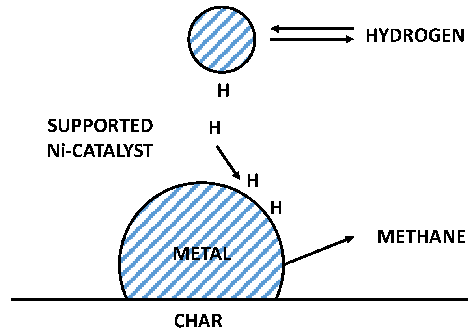
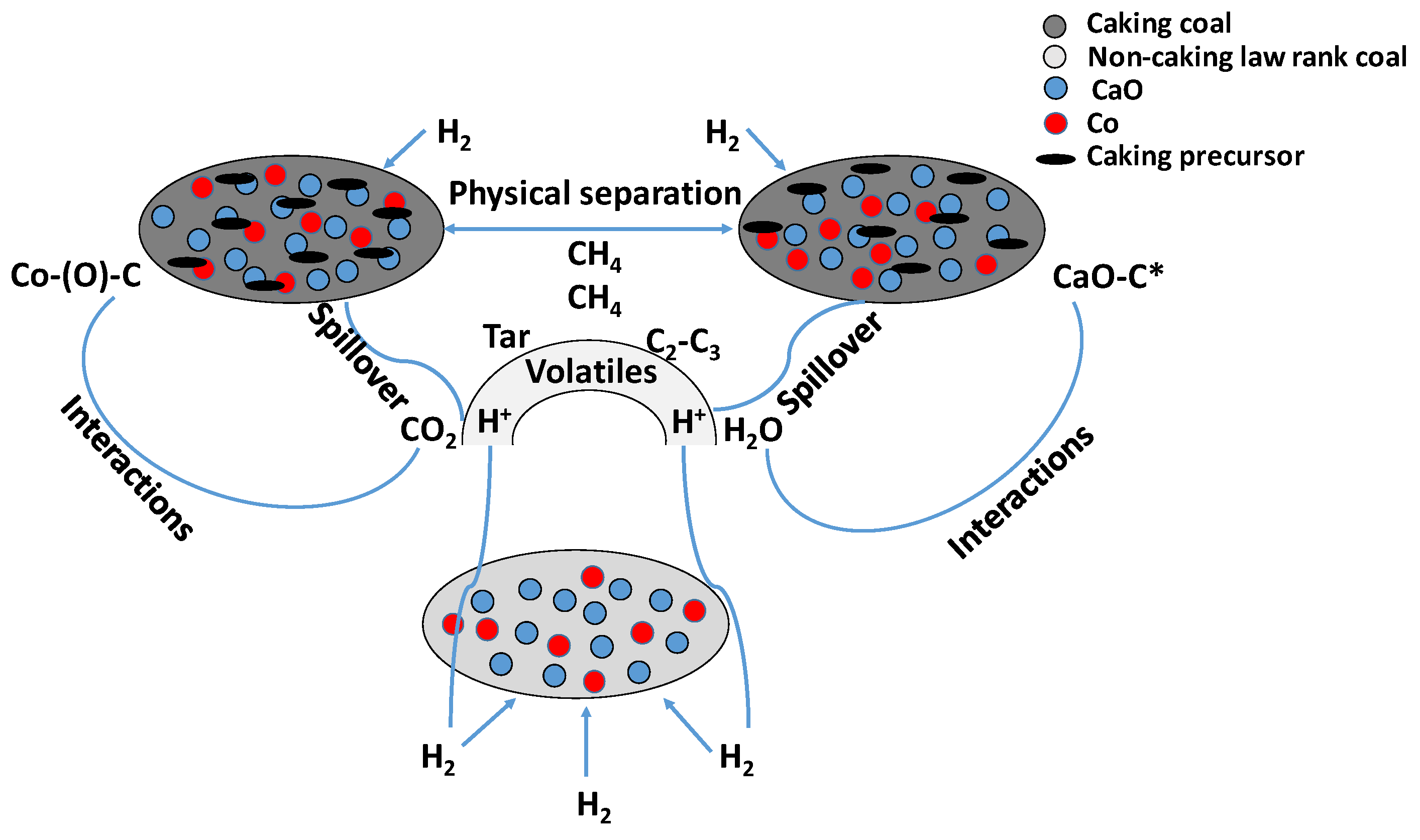
  • For medium-low-rank coals with non-caking behavior and low sulfur content, the probable mechanism could concern the supplying of active hydrogen by the Co-Ca catalyst and the C-C bonds’ catalytic fracturing, which is the determining step (Figure 16);
  • For caking coal, the caking agglomeration properties were damaged in situ by means of the blending of the coal, which improved coal reactivity due to the reduced contact between the cohesive coal particles (physical separation) as well as the activated hydrogen spillover, thus promoting the activity of the Co-Ca catalyst in the presence of volatile catalyst-coal interactions (Figure 16).
  • For high-rank coal with non-caking behavior and low/high sulfur content, the suitable amount of Ca compounds (CaO/CaCO3) influenced the hydrogenation of graphite carbon and limited the deactivation effect of sulfur on the Co-Ca catalyst; indeed, the H2S strongly absorbed onto the Co surface through its fixing on Co particles, which promote the catalyst activity (Equation (8)).
H 2 S   H 2 CaO + Co C CaS + Co 2 C CH 4 CaO
In another study [93], Qu et al. explained the role of Ca species’ participation in the Co-catalyzed coal hydrogasification process. The authors took as reference the work of Haga [89], who studied the Ni-Ca catalytic mechanism: calcium nitrate reacted with carbon, resulting in the generation of a calcium carboxylate structure (CaO(COO)) on the surface of coal, from which CO2 molecules could be released in the temperature range of 400–700 °C. These molecules reacted with Ni-C, resulting in the Ni-(O)-C generation, which was responsible for the high dispersion of Ni and the initial accelerated reaction rate. The same mechanism was proposed by Qu et al. for the Co-Ca catalysts. In particular, in this case, the Co-(O)-C was ultimately developed in the form of CO. From the catalytic pyrolysis stage, a great amount of “nascent” activated carbon was obtained in the form of Co-C* and CaO-C*, which have an inborn reactivity toward hydrogenation reactions. From there on, the dominant step was the consumption of amorphous carbon (Ca) which was abundant at the reactive edges, where the hydrogen radicals easily attacked the carbon atoms. The cooperation of 5% Co and 1% Ca enhanced the dispersion of the catalyst on the coal surface, hence creating more active sites up to this point. Consequently, the spillover of the active hydrogen occurred, from the dispersed Co catalyst surface to the interface between the catalyst and coal char; the resulting saturation of active sites came with the edge hydrogenation to form -CH2 group, while ring opening produced methyl groups that can be hydrogenated to produce CH4. The authors pointed out that the role of Ca in the catalyst was related to the modification of the reaction activity of the Co-Cg group. In fact, Ca facilitates the breaking of C-C bonds in Co-Cg structures, which is instead extremely slow when Co is used alone: this phenomenon occurs due to the highly stable π-electron cloud of the condensed aromatic rings and their slow hydrogenation and opening [132]. In particular, the authors proposed that during the 850 °C reaction, the CaO went through surface diffusion (because the CaO Hutting temperature is 593 °C), interacting with Co-Cg to form the reactive Co-Cg-OCa structure, whose reactive sites could be readily attacked by hydrogen and undergo to the steps of amorphous carbon hydrogasification. Lastly, it is worthwhile to note that an increase in the Ca loading amount promoted the in situ transformation of Ca to C*, while an increase in the Co loading amount promoted the in situ transformation of Cg to Ca. This explains that the excellent performance of the 5% Co–1% Ca catalyst (90 wt% carbon conversion and 77.3 wt% methane yield in 30 min) was achieved through the formation of the reaction chain Cg→Ca→C*.
The catalytic performance of the various formulations employed for coal/biomass hydrogasification described above are summarized and compared in Table 4. Due to the difference in the operative conditions, the reactor configurations, and the nature of the carbonaceous matrices, it is hard to identify better solutions. However, it is possible to state that the choice of calcium as catalytic species enhances the methane production rates. In particular, the highest CH4 production was recorded for the Ca-Co-based catalysts (70–72 mL∙(min∙gcoal)−1) or by doping the catalysts with alkaline and alkaline-earth compounds. Conversely, the Co-Cu combination displayed less beneficial results. Thus, the current review highlighted that the Co-Ca formulation is able to reach the highest SNG production.
However, in view of the industrial development of the hydrogasification process, looking at the catalyst choice, it is clear that, besides the activity performance, the most suitable solution should combine cheap formulations, recoverability, and low pollution effects. In this regard, in order to reduce the final impact of the catalyst on the process economy, the long-term stability of the best formulation as well as the catalyst recoverability require further investigations. In fact, looking at the results shown in Table 4, only a few researchers [86,97,105] selected reaction times of the order of 8 h which, are clearly incompatible with an industrial plant.
A possible solution to the above issues can be offered by cheap formulations (for example, containing Ni), employed by various researchers [133,134,135] for reforming as well as methanation reactions, which displayed high stability during time-on-stream tests and promising regeneration properties. In addition, the employment of rare earth oxides as catalytic support could be proposed as a valid alternative in order to prevent catalyst deactivation phenomena.

4. Conclusions

Global warming and fossil fuel depletion encourage the exploitation of renewable resources. However, due to the actual demand for both chemicals and energy, the scenario in which fossil feedstocks can be completely replaced by renewables is currently unrealistic. On the other hand, from an engineering point of view, it can be useful to apply the technologies developed for traditional fuels to the case of renewables (i.e., biomass). In this regard, the hydrogasification process, mainly investigated for coal feedstocks, or the co-hydrogasification (i.e., simultaneous hydrogasification of renewable and fossil matrices) offers a viable alternative for the partial replacement of coal as an energy source. Nonetheless, despite hydrogasification having several advantages compared to the gasification process, researchers have still paid little attention to this technology, especially in the case of biomass. The present review is mainly focused on the progress related both to the plant layouts as well as reactor configurations and the catalytic formulations proposed to improve the process efficiency.
In this regard, different plant configurations have been investigated for the production of SNG, light hydrocarbons, and even methanol. Such layouts include electrolysis units or fuel cells and propose efficient solutions for the contemporary generation of H2 streams for the gasifier and electricity. In many cases, units other than the hydrogasifer were included (i.e., reformer, WGS, or methanation reactor), and the obtained energy efficiency, independent of the feedstock, ranged from 40 to 74%. The route of feeding low-purity streams to the gasifier (for example, containing CO2) was also identified as a cheaper alternative for increasing the CH4 yield. The addition of plastic materials both to coal and biomass feedstocks is also useful for enhancing the SNG production rate.
Issues related to reactor configurations were also faced. The starting idea was to use the typical fluidized bed employed in gasification processes. However, other configurations (i.e., the entrained flow-bed or the two-stage fluidized bed) have been proposed to exploit the benefits of fluidized bed reactors (short residence time and good solid-gas contact), avoiding, at the same time, particle agglomeration as well as reducing by-product selectivity (especially CO2 emissions).
Due to the slow kinetics of the hydrogasification reaction, the choice of proper catalysts is mandatory to obtain the desired process performance. In some cases, the coal-biomass co-hydrogasification displayed a catalytic push due to the metal impurities contained in the feedstock. As a result of the synergistic effect between the two matrices, a significant enhancement in the yield toward CH4 and light hydrocarbons was observed. The Ca-promoted iron-group metals-based catalysts are the most promising samples for the char hydrogasification of both coal and biomass. The Ca addition, in fact, modifies the catalytic behavior of iron group metals, approaching the catalytic behavior of Rh or Pt, which are more active but too expensive for industrial utilization. Concerning the Co-based series, the 5 wt% Co–1 wt% Ca catalyst showed the best performance thanks to its superior ability related to the breakage of the amorphous C-C bonds, the promotion of coal devolatilization, the inhibition of coal graphitization, and the production of active sites on the char surface. This catalyst was able to obtain 90.0 wt% carbon conversion and 77.3 wt% of CH4 yield in 30 min at 850 °C and 3 MPa, for example. Even if Co and Ni are the most effective catalysts for the process, their high cost can hinder the feasibility of the process; therefore, the use of cheaper but more highly active catalysts was investigated, including both iron (which, in the 5 wt% Fe–1 wt% Ca catalyst, allows for obtaining a noticeable increment of 45.6% of the CH4 yield) and copper composite Cu-Ni-Ca catalysts, which are active and recoverable but have pollution issues. Moreover, iron, nickel, and Ca-based catalysts were shown to promote H2 spillover phenomena, enhancing the C-C bond-breaking rates. A remarkable alternative to the previous possibility is the use of alkaline and alkaline-earth compounds, both contained in the biomass/coal char and in added compounds and which show high activity (even higher than transition metals) and selectivity to CH4. In this regard, it was also shown that alkaline compounds are helpful to promote the conversion of sulfur compounds, which are responsible for catalyst deactivation (especially in the case of iron particles). On the contrary, such species are characterized by difficulties during the recovery process and losses by vaporization under high reaction temperatures.
The current review highlights the benefits of coal/biomass hydrogasification processes, pointing out, at the same time, the engineering bottlenecks, which actually hinder the industrial application of this technology. Based on the above discussion, it is clear that the partial substitution of coal by biomass is highly desired and great efforts were made toward the application of coal’s well-established technologies to renewable sources (i.e., biomass). The different plant configurations proposed for coal/biomass hydrogasification appear very interesting, with theoretically high production rates and efficiencies. However, in the majority of the cases, the designed plants have not been constructed yet, and the studies have only reached the simulation stage. In the case of the reactor configurations, as well, further studies are still required to propose more interesting alternatives with respect to the typical solutions offered in the case of gasification. Concerning the catalytic formulations, despite the promising results obtained, in the majority of cases, the activity tests were performed a limited number of times, which actually are not competitive in view of industrial applications. In fact, there is a lack of research concerning the deactivation phenomena occurring during hydrogasification. In addition, the choice of catalyst should address several issues related to low cost, recoverability, and pollution effects. Moreover, one of the main obstacles to the industrial development of biomass hydrogasification lies in the higher tar formation compared to the coal gasification process. This complex mixture of hydrocarbons, in fact, may cause several technical issues during industrial plant operations.
Coal/biomass hydrogasification is a high-potential process, due to the reduced pollutant emissions with respect to conventional processes and the chance of exploiting renewable resources through co-hydrogasification. However, the extensive exploitation of biomass for chemical/energy generation is still far away and the technical issues during operation partially hinder the development of this technology. More widespread utilization of biomass feedstocks for different purposes, which is highly desired here (hopefully within 10 years), will certainly boost the hydrogasification process.
The technical and technological barriers to the industrialization of the hydrogasification process have been partially overcome through the design of suitable reactors and catalysts or through the simulation of efficient plant layouts. However, in the future, researchers still have to face issues related to the identification of the best reactor configurations and most stable catalyst formulations as well as the most energy-efficient plant layouts. Nonetheless, the implementation of new technologies for dealing with the high tar amounts produced during biomass hydrogasification and the identification of cheap H2 sources is highly desired.

Author Contributions

Conceptualization, C.R. and E.S.; methodology, V.P.; investigation, C.R.; resources, E.S.; data curation, V.P.; writing—review and editing, C.R. and E.S.; visualization, C.R. and E.S.; supervision, V.P. All authors have read and agreed to the published version of the manuscript.

Funding

This research received no external funding.

Data Availability Statement

Not applicable.

Conflicts of Interest

The authors declare no conflict of interest.

Abbreviations

AAEMAlkali and alkaline rare metals
BTXBenzene, toluene, and xylene
C*Activated carbon
CaAmorphous carbon
CgGraphite carbon
CCHG Coal catalytic hydrogasification
CCHP Coal catalytic hydropyrolysis
CECCation exchange capacity
CnHmLight hydrocarbons
HCL High-value-added liquid hydrocarbons
LAH Light aromatic hydrocarbons
MCFC Molten Carbonate Fuel Cells
MSCF One thousand standard cubic feet
NumberfluidizationFluidization number
PCDDS Polychlorinated diben-zo-p-dioxins
PCX Phenol, cresol, and xylenol
RDFRefuse-derived fuel
SEM Scanning Electron Microscopy
SNG Substitute Natural Gas
SOFC Solid Oxide Fuel Cells
TimereactionReaction time
TimeresidenceResidence time
U Gas velocity
UCG Underground Coal Hydrogasification
UmfMinimum fluidization velocity
VCH4Methane formation rate
VER Variable Energy Resources
WGS Water Gas Shift
XcharChar conversion
XcarbonCarbon conversion
XRD X-ray diffraction
YCH4Methane yield
ZEC Zero Emission Carbon

References

  1. Alshorifi, F.T.; Ali, S.L.; Salama, R.S. Promotional Synergistic Effect of Cs–Au NPs on the Performance of Cs–Au/MgFe2O4 Catalysts in Catalysis 3,4-Dihydropyrimidin-2(1H)-Ones and Degradation of RhB Dye. J. Inorg. Organomet. Polym. Mater. 2022, 32, 3765–3776. [Google Scholar] [CrossRef]
  2. Alshorifi, F.T.; Alswat, A.A.; Salama, R.S. Gold-selenide quantum dots supported onto cesium ferrite nanocomposites for the efficient degradation of rhodamine B. Heliyon 2022, 8, e09652. [Google Scholar] [CrossRef]
  3. El-Hakam, S.A.; Alshorifi, F.T.; Salama, R.S.; Gamal, S.; El-Yazeed, W.S.A.; Ibrahim, A.A.; Ahmed, A.I. Application of nanostructured mesoporous silica/ bismuth vanadate composite catalysts for the degradation of methylene blue and brilliant green. J. Mater. Res. Technol. 2022, 18, 1963–1976. [Google Scholar] [CrossRef]
  4. Keefer, B.G.; Babicki, M.L.; Sellars, B.G.; Ng, E. Method and System for Biomass Hydrogasification. U.S. Patent 9,394,171 B2, 19 July 2016. [Google Scholar]
  5. García-Mateos, F.J.; Moulefera, I.; Rosas, J.M.; Benyoucef, A.; Rodríguez-Mirasol, J.; Cordero, T. Alcohol Dehydrogenation on Kraft Lignin-Derived Chars with Surface Basicity. Catalysts 2017, 7, 308. [Google Scholar] [CrossRef] [Green Version]
  6. Yin, H.; Yip, A.C.K. A Review on the Production and Purification of Biomass-Derived Hydrogen Using Emerging Membrane Technologies. Catalysts 2017, 7, 297. [Google Scholar] [CrossRef] [Green Version]
  7. Yong, Z.J.; Bashir, M.J.K.; Ng, C.A.; Sethupathi, S.; Lim, J.W.; Show, P.L. Sustainable Waste-to-Energy Development in Malaysia: Appraisal of Environmental, Financial, and Public Issues Related with Energy Recovery from Municipal Solid Waste. Processes 2019, 7, 676. [Google Scholar] [CrossRef] [Green Version]
  8. Jiang, J.; Liu, Q.; Liu, Z. Superior catalytic effect of calcium oxide on the hydrogasification of char for CH4. Fuel 2016, 180, 737–742. [Google Scholar] [CrossRef]
  9. Liu, Z.; Norbeck, J.M.; Raju, A.S.K.; Kim, S.; Park, C.S. Synthetic natural gas production by sorption enhanced steam hydrogasification based processes for improving CH4 yield and mitigating CO2 emissions. Energy Convers. Manag. 2016, 126, 256–265. [Google Scholar] [CrossRef]
  10. Pankiewicz-Sperka, M.; Kapusta, K.; Basa, W.; Stolecka, K. Characteristics of Water Contaminants from Underground Coal Gasification (UCG) Process—Effect of Coal Properties and Gasification Pressure. Energies 2021, 14, 6533. [Google Scholar] [CrossRef]
  11. Kapusta, K.; Wiatowski, M.; Thomas, H.R.; Zagorščak, R.; Sadasivam, S.; Masum, S.; Kempka, T.; Otto, C.; Basa, W.; Szyja, M.; et al. Experimental simulations of methane-oriented underground coal gasification using hydrogen—The effect of coal rank and gasification pressure on the hydrogasification process. Int. J. Hydrogen Energy 2023, 48, 921–932. [Google Scholar] [CrossRef]
  12. Burchart, D.; Gazda-Grzywacz, M.; Grzywacz, P.; Burmistrz, P.; Zarębska, K. Life Cycle Assessment of Hydrogen Production from Coal Gasification as an Alternative Transport Fuel. Energies 2023, 16, 383. [Google Scholar] [CrossRef]
  13. Zhang, A.; Kaiho, M.; Yasuda, H.; Zabat, M.; Nakano, K.; Yamada, O. Fundamental studies on hydrogasification of Taiheiyo coal. Energy 2005, 30, 2243–2250. [Google Scholar] [CrossRef]
  14. Yan, L.; Yue, G.; He, B. Exergy analysis of a coal/biomass co-hydrogasification based chemical looping power generation system. Energy 2015, 93, 1778–1787. [Google Scholar] [CrossRef]
  15. Wang, X.; Yao, K.; Huang, X.; Chen, X.; Yu, G.; Liu, H.; Wang, F.; Fan, M. Effect of CaO and biomass ash on catalytic hydrogasification behavior of coal char. Fuel 2019, 249, 103–111. [Google Scholar] [CrossRef]
  16. Mozaffarian, M.; Zwart, R.W.R. Production of Substitute Natural Gas by Biomass Hydrogasification. In Progress in Thermochemical Biomass Conversion; Blackwell Science Ltd.: Oxford, UK, 2001; pp. 405–419. [Google Scholar] [CrossRef]
  17. Safavi, A.; Richter, C.; Unnthorsson, R. Dioxin Formation in Biomass Gasification: A Review. Energies 2022, 15, 700. [Google Scholar] [CrossRef]
  18. Steinberg, M. Hydro-Gasification of Coal for Hydrogen Production with Reduced CO2 Emission. In Proceedings of the WHEC16: 16. World Hydrogen Energy Conference, Lyon, France, 13–16 June 2006. [Google Scholar]
  19. Zhu, Y.; Wang, Q.; Li, K.; Cen, J.; Fang, M.; Ying, C. Study on pressurized isothermal pyrolysis characteristics of low-rank coal in a pressurized micro-fluidized bed reaction analyzer. Energy 2022, 240, 122475. [Google Scholar] [CrossRef]
  20. Frigo, S.; Spazzafumo, G. Cogeneration of power and substitute of natural gas using biomass and electrolytic hydrogen. Int. J. Hydrogen Energy 2018, 43, 11696–11705. [Google Scholar] [CrossRef]
  21. Han, G.-F.; Zhang, P.; Scholzen, P.; Noh, H.-J.; Yang, M.; Kweon, D.H.; Jeon, J.-P.; Kim, Y.H.; Kim, S.-W.; Han, S.-P.; et al. Extreme Enhancement of Carbon Hydrogasification via Mechanochemistry. Angew. Chem. Int. Ed. 2022, 61, e202117851. [Google Scholar] [CrossRef]
  22. Gil, S.; Smoliński, A. Experimental Study of Hydrogasification of Lignite and Subbituminous Coal Chars. Sci. World J. 2015, 2015, 867030. [Google Scholar] [CrossRef]
  23. Zhou, Y.; Zheng, Y.; Wang, W.X.; Zheng, C.G. An Experimental Investigation on Hydrogasification of Coal Chars in a Fixed Bed Reactor under High Pressure. In Advanced Materials Research; Trans Tech Publications: Zurich, Switzerland, 2012; pp. 863–870. [Google Scholar]
  24. Tomeczek, J.; Gil, S. The kinetics of coal chars hydrogasification. Fuel Process. Technol. 2010, 91, 1564–1568. [Google Scholar] [CrossRef]
  25. Miller, D.J. Enhanced Coal Hydrogasification via Oxidative Pretreatment; Michigan State University: East Lansing, MI, USA, 1992; 79p. [Google Scholar] [CrossRef] [Green Version]
  26. Woźniak, G.; Longwic, R.; Szydło, K.; Kryłowicz, A.; Kryłowicz, J.; Juszczak, R. The EFFICIENCY of the process of Coal Gasification in the Presence of Hydrogen. In E3S Web of Conferences; EDP Sciences: Les Ulis, France, 2018; p. 00030. [Google Scholar]
  27. Liu, X.; Xiong, B.; Huang, X.; Ding, H.; Zheng, Y.; Liu, Z.; Zheng, C. Effect of catalysts on char structural evolution during hydrogasification under high pressure. Fuel 2017, 188, 474–482. [Google Scholar] [CrossRef]
  28. González, J.F.; Ramiro, A.; Sabio, E.; Encinar, J.M.; González, C.M. Hydrogasification of Almond Shell Chars. Influence of Operating Variables and Kinetic Study. Ind. Eng. Chem. Res. 2002, 41, 3557–3565. [Google Scholar] [CrossRef]
  29. Toomajian, M.E.; Lussier, M.G.; Miller, D.J. Effect of oxidation and other treatments on hydrogasification rate of coal char. Fuel 1992, 71, 1055–1061. [Google Scholar] [CrossRef]
  30. Malekshahian, M.; Hill, J.M. Potassium catalyzed CO2 gasification of petroleum coke at elevated pressures. Fuel Process. Technol. 2013, 113, 34–40. [Google Scholar] [CrossRef]
  31. Zhang, Y.; Wan, L.; Guan, J.; Xiong, Q.; Zhang, S.; Jin, X. A Review on Biomass Gasification: Effect of Main Parameters on Char Generation and Reaction. Energy Fuels 2020, 34, 13438–13455. [Google Scholar] [CrossRef]
  32. Mishra, S.; Upadhyay, R.K. Review on biomass gasification: Gasifiers, gasifying mediums, and operational parameters. Mater. Sci. Energy Technol. 2021, 4, 329–340. [Google Scholar] [CrossRef]
  33. Tezer, Ö.; Karabağ, N.; Öngen, A.; Çolpan, C.Ö.; Ayol, A. Biomass gasification for sustainable energy production: A review. Int. J. Hydrogen Energy 2022, 47, 15419–15433. [Google Scholar] [CrossRef]
  34. Akbarian, A.; Andooz, A.; Kowsari, E.; Ramakrishna, S.; Asgari, S.; Cheshmeh, Z.A. Challenges and opportunities of lignocellulosic biomass gasification in the path of circular bioeconomy. Bioresour. Technol. 2022, 362, 127774. [Google Scholar] [CrossRef]
  35. Shahabuddin, M.; Alam, T. Gasification of solid fuels (coal, biomass and MSW): Overview, challenges and mitigation strategies. Energies 2022, 15, 4444. [Google Scholar] [CrossRef]
  36. Tosti, S.; Spazzafumo, G.; Capobianco, D.; Buceti, G.; Pozio, A.; Bartucca, S. EU scenarios of renewable coal hydro-gasification for SNG production. Sustain. Energy Technol. Assess. 2016, 16, 43–52. [Google Scholar] [CrossRef]
  37. Bargiacchi, E.; Candelaresi, D.; Valente, A.; Spazzafumo, G.; Frigo, S. Life Cycle Assessment of Substitute Natural Gas production from biomass and electrolytic hydrogen. Int. J. Hydrogen Energy 2021, 46, 35974–35984. [Google Scholar] [CrossRef]
  38. Veringa, H. Feasibility of Sng Production by Biomass Hydrogasification. In Proceedings of the 12th European Conference and Technology Exhibition on Biomass for Energy, Industry and Climate Protection, Amsterdam, The Netherlands, 17–21 June 2002. [Google Scholar]
  39. Zhang, J.; Wang, X.; Wang, F.; Wang, J. Investigation of hydrogasification of low-rank coals to produce methane and light aromatics in a fixed-bed reactor. Fuel Process. Technol. 2014, 127, 124–132. [Google Scholar] [CrossRef]
  40. Yan, S.; Zhang, J.; Yan, X.; Pan, D.; Ren, H.; Qu, X. Catalytic coal hydrogasification by cobalt-calcium catalyst in a pressurized fluidized bed: Role of hydropyrolysis and catalysis process. J. Anal. Appl. Pyrolysis 2018, 135, 251–259. [Google Scholar] [CrossRef]
  41. Tromp, P.J.J.; Kapteijn, F.; Moulijn, J.A. Characterization of coal pyrolysis by means of differential scanning calorimetry. 2. Quantitative heat effects in a H2 and in a CO2 atmosphere. Fuel Process. Technol. 1989, 23, 63–74. [Google Scholar] [CrossRef]
  42. Higman, C.; Tam, S. Advances in Coal Gasification, Hydrogenation, and Gas Treating for the Production of Chemicals and Fuels. Chem. Rev. 2014, 114, 1673–1708. [Google Scholar] [CrossRef]
  43. Scharf, H.-J.; Schrader, L.; Teggers, H. Results from the operation of a semi-technical test plant for brown coal hydrogasification. Nucl. Eng. Des. 1984, 78, 223–231. [Google Scholar] [CrossRef]
  44. Lee, S.H.; Lee, J.G.; Kim, J.H.; Choi, Y.C. Hydrogasification characteristics of bituminous coals in an entrained-flow hydrogasifier. Fuel 2006, 85, 803–806. [Google Scholar] [CrossRef]
  45. Minutillo, M.; Perna, A. Renewable energy storage system via coal hydrogasification with co-production of electricity and synthetic natural gas. Int. J. Hydrogen Energy 2014, 39, 5793–5803. [Google Scholar] [CrossRef]
  46. Perdikaris, N.; Panopoulos, K.D.; Fryda, L.; Kakaras, E. Design and optimization of carbon-free power generation based on coal hydrogasification integrated with SOFC. Fuel 2009, 88, 1365–1375. [Google Scholar] [CrossRef]
  47. Hobbs, R. Development of a Hydrogasification Process for Co-Production of Substitute Natural Gas (SNG) and Electric Power from Western Coals-Phase I; Arizona Public Service Company: Phoenix, AZ, USA, 2007. [Google Scholar] [CrossRef] [Green Version]
  48. Feng, J.; Yan, S.; Zhang, R.; Gu, S.; Qu, X.; Bi, J. Characteristics of Co–Ca catalyzed coal hydrogasification in a mixture of H2 and CO2 atmosphere. Fuel 2022, 324, 124486. [Google Scholar] [CrossRef]
  49. Nourozieh, H.; Kariznovi, M.; Chen, Z.; Abedi, J. Simulation Study of Underground Coal Gasification in Alberta Reservoirs: Geological Structure and Process Modeling. Energy Fuels 2010, 24, 3540–3550. [Google Scholar] [CrossRef]
  50. Yasuda, H.; Yamada, O.; Kaiho, M.; Nakagome, H. Effect of polyethylene addition to coal on hydrogasification enhancement. J. Mater. Cycles Waste Manag. 2014, 16, 151–155. [Google Scholar] [CrossRef]
  51. Yasuda, H.; Yamada, O.; Zhang, A.; Nakano, K.; Kaiho, M. Hydrogasification of coal and polyethylene mixture. Fuel 2004, 83, 2251–2254. [Google Scholar] [CrossRef]
  52. HYGAS: 1964 to 1972. In Pipeline Gas from Coal—Hydrogenation (IGT Hydrogasification Process); Institute of Gas Technology: Chicago, IL, USA, 1975; Volume 4, 588p. [CrossRef]
  53. Michael, E. An Analysis of Coal Hydrogasification Processes; Department of Energy: Washington, DC, USA, 1978; pp. 12–100. [Google Scholar]
  54. Friedman, J. Development of a Single-Stage, Entrained-Flow, Short-Residence-Time Hydrogasifier. Rep. US Dep. Energy FE 1979, 2518, 24. [Google Scholar]
  55. Falk, A.; Schuman, M.; Kahn, D. Advancement of Flash Hydrogasification: Task VIII. Performance Testing; Rockwell International Corp: Canoga Park, CA, USA, 1986. [Google Scholar]
  56. Stroud, H.; Noguchi, F. 55th Autumn Meeting of Institute of Gas Engineers; Institute of Gas Engineering Commission: Derby, UK, 1989; pp. 1403–1406. [Google Scholar]
  57. Yuan, S.; Bi, J.; Qu, X.; Lu, Q.; Cao, Q.; Li, W.; Yao, G.; Wang, Q.; Wang, J. Coal hydrogasification: Entrained flow bed design-operation and experimental study of hydrogasification characteristics. Int. J. Hydrogen Energy 2018, 43, 3664–3675. [Google Scholar] [CrossRef]
  58. Xia, Z.; Yan, S.; Chen, C.; Qu, X.; Bi, J. Three-dimensional simulation of coal catalytic hydrogasification in a pressurized bubbling fluidized bed. Energy Convers. Manag. 2021, 250, 114874. [Google Scholar] [CrossRef]
  59. Zhang, J.; Wu, X.; Qian, Y.; Wang, J. Formation behaviors of gas and liquid products during the two-stage hydrogasification of low-rank coal. Fuel 2015, 150, 217–225. [Google Scholar] [CrossRef]
  60. Yan, S.; Qu, X.; Xia, Z.; Chen, C.; Bi, J. Effect of experimental variables on coal catalytic hydrogasification in a pressurized fluidized bed. Fuel 2022, 307, 121761. [Google Scholar] [CrossRef]
  61. Hüttinger, K.J.; Michenfelder, A. Hydrogasification of Brown Coal-Chemism, Kinetics and Technical Aspects. In Carbon and Coal Gasification; Springer: Dordrecht, The Netherlands, 1986; pp. 485–507. [Google Scholar]
  62. Yan, L.; He, B.; Pei, X.; Wang, C.; Li, X.; Duan, Z. Kinetic Models for Coal Hydrogasification and Analyses of Hydrogasification Characteristics in Entrained-Flow Gasifiers. Energy Fuels 2013, 27, 6388–6396. [Google Scholar] [CrossRef]
  63. Tosti, S.; Sousa, M.A.; Buceti, G.; Madeira, L.M.; Pozio, A. Process analysis of refuse derived fuel hydrogasification for producing SNG. Int. J. Hydrogen Energy 2019, 44, 21470–21480. [Google Scholar] [CrossRef]
  64. Steinberg, M.; Grohse, E.W.; Tung, Y. A Feasibility Study for the Coprocessing of Fossil Fuels with Biomass by the Hydrocarb Process; Environmental Protection Agency: Washington, DC, USA, 1991; 92p. [Google Scholar]
  65. Buceti, G.; Tosti, S.; Pozio, A. Idrogassificazione di rifiuti—Metano da energie rinnovabili e combustibile derivato dai rifiuti: Un’alternativa ai processi di incenerimento e termovalorizzazione. La Chimica e L’industria—Rivista Della Società Chimica Italiana 2017, 4, 18–26. [Google Scholar] [CrossRef]
  66. Barbuzza, E.; Buceti, G.; Pozio, A.; Santarelli, M.; Tosti, S. Gasification of wood biomass with renewable hydrogen for the production of synthetic natural gas. Fuel 2019, 242, 520–531. [Google Scholar] [CrossRef]
  67. Frigo, S.; Spazzafumo, G. Comparison of different system layouts to generate a substitute of natural gas from biomass and electrolytic hydrogen. Int. J. Hydrogen Energy 2020, 45, 26166–26178. [Google Scholar] [CrossRef]
  68. Yan, L.; He, B.; Pei, X.; Wang, C.; Duan, Z.; Song, J.; Li, X. Design and comparisons of three biomass based hydrogen generation systems with chemical looping process. Int. J. Hydrogen Energy 2014, 39, 17540–17553. [Google Scholar] [CrossRef]
  69. Steinberg, M. Process for Conversion of Coal to Substitute Natural Gas (SNG); HCE LLC: Hawthorne, CA, USA, 2005. [Google Scholar]
  70. Gu, J.; Yang, S.; Kokossis, A. Modeling and Analysis of Coal-Based Lurgi Gasification for LNG and Methanol Coproduction Process. Processes 2019, 7, 688. [Google Scholar] [CrossRef] [Green Version]
  71. Steinberg, M. Co-Processing Coal and Natural Gas by the Hynol Process for Enhanced Methanol Production and Reduced CO2 Emissions; Department of Energy: Washington, DC, USA, 1997; 27p. [Google Scholar] [CrossRef] [Green Version]
  72. Ogunjemilusi, D.; Omotayo, F.; Igbinosun, E. Hynol Process for the Gasification of Microbial in Biomass for the Production of Methanol Fuel (CH 4 OH). Int. J. Multidiscip. Sci. Adv. Technol. 2021, 2, 9–19. [Google Scholar] [CrossRef]
  73. Sellars, B.G.; Babicki, M.L.; Keefer, B.G.; Ng, E. Method of hydrogasification of Biomass to Methane with Low Depositable Tars. U.S. Patent, 8,383,871, 26 February 2013. [Google Scholar]
  74. Scott, D.S. Hydrogasification of Biomass to Produce High Yields of Methane. U.S. Patent, 4,822,935, 18 April 1989. [Google Scholar]
  75. You, S.-H.; Jang, H.-T.; Cha, W.-S. Hydrogasification of Mixture Composed of Plastics and Biomass. In Proceedings of the KAIS Fall Conference; The Korea Academia-Industrial Cooperation Society: Cheonan, Republic of Korea, 2011; pp. 283–285. [Google Scholar]
  76. Porada, S. A comparison of basket willow and coal hydrogasification and pyrolysis. Fuel Process. Technol. 2009, 90, 717–721. [Google Scholar] [CrossRef]
  77. Oruc, O.; Dincer, I. Evaluation of hydrogen production with iron-based chemical looping fed by different biomass. Int. J. Hydrogen Energy 2020, 45, 34557–34565. [Google Scholar] [CrossRef]
  78. Zhang, J.; Zheng, N.; Wang, J. Co-hydrogasification of lignocellulosic biomass and swelling coal. IOP Conf. Ser. Earth Environ. Sci. 2016, 40, 012042. [Google Scholar] [CrossRef] [Green Version]
  79. Zhu, H.; Wang, X.; Chen, X.; Yu, G. Effect of Biomass Char Additives on the Hydrogasification Behavior of a Bituminous Coal. BioResources 2016, 11, 9002–9016. [Google Scholar] [CrossRef] [Green Version]
  80. Islam, M.W. A review of dolomite catalyst for biomass gasification tar removal. Fuel 2020, 267, 117095. [Google Scholar] [CrossRef]
  81. Valderrama Rios, M.L.; González, A.M.; Lora, E.E.S.; Almazán del Olmo, O.A. Reduction of tar generated during biomass gasification: A review. Biomass Bioenergy 2018, 108, 345–370. [Google Scholar] [CrossRef]
  82. Skodras, G.; Panagiotidou, S.; Kokorotsikos, P.; Serafidou, M. Potassium catalyzed hydrogasification of low-rank coal for synthetic natural gas production. Open Chem. 2016, 14, 92–109. [Google Scholar] [CrossRef]
  83. Qu, X.; Wang, Q.-F.; Yan, S.; Feng, J.; Zhang, J.-S.; Zhang, R.; Bi, J.-C. The behavior of the different catalysts for model carbon hydrogasification. J. Fuel Chem. Technol. 2022, 50, 1–10. [Google Scholar] [CrossRef]
  84. Maneewan, K.; Krerkkaiwan, S.; Sunphorka, S.; Vitidsant, T.; Kuchonthara, P. Catalytic Effect of Biomass Pyrolyzed Char on the Atmospheric Pressure Hydrogasification of Giant Leucaena (Leucaena leucocephala) Wood. Ind. Eng. Chem. Res. 2014, 53, 11913–11919. [Google Scholar] [CrossRef]
  85. Tomita, A.; Tamai, Y. Hydrogenation of carbons catalyzed by transition metals. J. Catal. 1972, 27, 293–300. [Google Scholar] [CrossRef]
  86. Zhang, F.; Sun, H.; Bi, J.; Qu, X.; Yan, S.; Zhang, J.; Zhang, J. The evolution of Fe and Fe-Ca catalysts during char catalytic hydrogasification. Fuel 2019, 257, 116040. [Google Scholar] [CrossRef]
  87. Matsumoto, S. Catalyzed hydrogasification of Yallourn char in the presence of supported hydrogenation nickel catalyst. Energy Fuels 1991, 5, 60–63. [Google Scholar] [CrossRef]
  88. Murakami, K.; Arai, M.; Shirai, M. Hydrogasification of Loy Yang brown coal by ion-exchanged nickel species. Energy Fuels 2000, 14, 1240–1244. [Google Scholar] [CrossRef]
  89. Haga, T.; Ozaki, J.-I.; Suzuki, K.; Nishiyama, Y. Role of MgO and CaO promoters in Ni-catalyzed hydrogenation reactions of CO and carbon. J. Catal. 1992, 134, 107–117. [Google Scholar] [CrossRef]
  90. Haga, T.; Nishiyama, Y. Promotion of iron-group catalysts by a calcium salt in hydrogasification of carbons at elevated pressures. Ind. Eng. Chem. Res. 1987, 26, 1202–1206. [Google Scholar] [CrossRef]
  91. Yan, S.; Bi, J.; Qu, X. The behavior of catalysts in hydrogasification of sub-bituminous coal in pressured fluidized bed. Appl. Energy 2017, 206, 401–412. [Google Scholar] [CrossRef]
  92. Yuan, S.; Zhang, N.; Qu, X.; Bi, J.; Cao, Q.; Wang, J. Promoted catalysis of calcium on the hydrogasification reactivity of iron-loaded subbituminous coal. Fuel 2017, 200, 153–161. [Google Scholar] [CrossRef]
  93. Qu, X.; Yan, S.; Yan, X.; Zhang, J.; Zheng, Q.; An, Y. Role of cobalt and calcium on coal catalytic hydrogasification in a pressurized fluidized bed. Fuel 2019, 239, 347–356. [Google Scholar] [CrossRef]
  94. Feng, J.; Yan, S.; Zhang, R.; Gu, S.; Qu, X.; Bi, J. Recycling and reuse performance of cobalt catalyst for coal hydrogasification. Fuel 2023, 335, 126939. [Google Scholar] [CrossRef]
  95. Yuan, S.; Qu, X.; Zhang, R.; Bi, J. Effect of calcium additive on product yields in hydrogasification of nickel-loaded Chinese sub-bituminous coal. Fuel 2015, 147, 133–140. [Google Scholar] [CrossRef]
  96. Bridier, B.; Perez-Ramirez, J. Cooperative effects in ternary Cu−Ni−Fe catalysts lead to enhanced alkene selectivity in alkyne hydrogenation. J. Am. Chem. Soc. 2010, 132, 4321–4327. [Google Scholar] [CrossRef]
  97. Sun, H.; Zhang, F.; Bi, J.; Qu, X.; Yan, S.; Zhang, J.; Zhang, J. Study of cu–Ni–ca composite catalysts in catalytic hydrogasification of char. Energy Fuels 2019, 33, 9661–9670. [Google Scholar] [CrossRef]
  98. Liu, H.; Huang, Z.; Kang, H.; Li, X.; Xia, C.; Chen, J.; Liu, H. Efficient bimetallic NiCu-SiO2 catalysts for selective hydrogenolysis of xylitol to ethylene glycol and propylene glycol. Appl. Catal. B Environ. 2018, 220, 251–263. [Google Scholar] [CrossRef]
  99. Freitas, I.C.; Manfro, R.L.; Souza, M.M. Hydrogenolysis of glycerol to propylene glycol in continuous system without hydrogen addition over Cu-Ni catalysts. Appl. Catal. B Environ. 2018, 220, 31–41. [Google Scholar] [CrossRef]
  100. Gandarias, I.; Requies, J.; Arias, P.; Armbruster, U.; Martin, A. Liquid-phase glycerol hydrogenolysis by formic acid over Ni–Cu/Al2O3 catalysts. J. Catal. 2012, 290, 79–89. [Google Scholar] [CrossRef]
  101. Pan, Z.; Wang, R.; Chen, J. Deoxygenation of methyl laurate as a model compound on Ni-Zn alloy and intermetallic compound catalysts: Geometric and electronic effects of oxophilic Zn. Appl. Catal. B Environ. 2018, 224, 88–100. [Google Scholar] [CrossRef]
  102. Han, Q.; Rehman, M.U.; Wang, J.; Rykov, A.; Gutiérrez, O.Y.; Zhao, Y.; Wang, S.; Ma, X.; Lercher, J.A. The synergistic effect between Ni sites and Ni-Fe alloy sites on hydrodeoxygenation of lignin-derived phenols. Appl. Catal. B Environ. 2019, 253, 348–358. [Google Scholar] [CrossRef]
  103. Li, C.; Xu, G.; Zhai, Y.; Liu, X.; Ma, Y.; Zhang, Y. Hydrogenation of biomass-derived ethyl levulinate into γ-valerolactone by activated carbon supported bimetallic Ni and Fe catalysts. Fuel 2017, 203, 23–31. [Google Scholar] [CrossRef]
  104. Hu, B.; Yin, Y.; Liu, G.; Chen, S.; Hong, X.; Tsang, S.C.E. Hydrogen spillover enabled active Cu sites for methanol synthesis from CO2 hydrogenation over Pd doped CuZn catalysts. J. Catal. 2018, 359, 17–26. [Google Scholar] [CrossRef]
  105. Sun, H.; Wang, J.; Bi, J.; Zhang, R.; Qu, X.; Zhang, J.; Zhang, J. Investigating the Cu-based catalysts for char catalytic hydrogasification and its recovery. Fuel 2021, 294, 120567. [Google Scholar] [CrossRef]
  106. Zoheidi, H.; Miller, D.J. Role of oxygen surface groups in catalysis of hydrogasification of carbon black by potassium carbonate. Carbon 1987, 25, 809–819. [Google Scholar] [CrossRef]
  107. Gardner, N.; Samuels, E.; Wilks, K. Catalyzed Hydrogasification of Coal Chars. In Coal Gasification; American Chemical Society: New York, NY, USA, 1974; Volume 131, pp. 217–236. [Google Scholar] [CrossRef]
  108. Kokorotsikos, P.; Stavropoulos, G.; Sakellaropoulos, G. Effect of catalyst impregnation conditions on Greek lignite hydrogasification. Fuel 1986, 65, 1462–1465. [Google Scholar] [CrossRef]
  109. Sheth, A.C.; Sastry, C.; Yeboah, Y.D.; Xu, Y.; Agarwal, P. Catalytic gasification of coal using eutectic salts: Reaction kinetics for hydrogasification using binary and ternary eutectic catalysts. Fuel 2004, 83, 557–572. [Google Scholar] [CrossRef]
  110. Karcz, A.; Porada, S. The influence of coal rank on formation of gaseous hydrocarbons in hydrogasification of coal. Fuel 1996, 75, 641–645. [Google Scholar] [CrossRef]
  111. Chin, G.; Guifen, L.; Qushi, D. New approach for gasification of coal char. Fuel 1987, 66, 859–863. [Google Scholar] [CrossRef]
  112. Zhang, J.; Zhang, L.; Yang, Z.; Yan, Y.; Mao, Y.; Bi, J. Effect of bauxite additives on ash sintering characteristics during the K2CO3-catalyzed steam gasification of lignite. RSC Adv. 2015, 5, 6720–6727. [Google Scholar] [CrossRef]
  113. Hong, B.; Wang, X.; Zhou, Z.; Yu, G. A Comparison of the Gas-Product-Release Characteristics from Coal Pyrolysis and Hydrogasification. Energy Technol. 2013, 1, 449–456. [Google Scholar] [CrossRef]
  114. Cypres, R.; Furfari, S. Fixed-bed pyrolysis of coal under hydrogen pressure at low heating rates. Fuel 1981, 60, 768–778. [Google Scholar] [CrossRef]
  115. Arendt, P.; van Heek, K.-H. Comparative investigations of coal pyrolysis under inert gas and H2 at low and high heating rates and pressures up to 10 MPa. Fuel 1981, 60, 779–787. [Google Scholar] [CrossRef]
  116. He, X.; Jin, L.; Wang, D.; Zhao, Y.; Zhu, S.; Hu, H. Integrated Process of Coal Pyrolysis with CO2 Reforming of Methane by Dielectric Barrier Discharge Plasma. Energy Fuels 2011, 25, 4036–4042. [Google Scholar] [CrossRef]
  117. Jiang, J.; Liu, Z.; Liu, Q. Synergetic Catalysis of Calcium Oxide and Iron in Hydrogasification of Char. Energy Fuels 2017, 31, 198–204. [Google Scholar] [CrossRef]
  118. Skodras, G.; Kokorotsikos, P.; Serafidou, M. Cation exchange capability and reactivity of low-rank coal and chars. Cent. Eur. J. Chem. 2014, 12, 33–43. [Google Scholar] [CrossRef]
  119. Hüttinger, K.J.; Krauss, W. Catalytic activity of coal minerals in hydrogasification of coal. Fuel 1981, 60, 93–102. [Google Scholar] [CrossRef]
  120. Yan, L.; He, B.; Ma, L.; Pei, X.; Wang, C.; Li, M.; Song, J. Numerical study with ChemKin for hydrogasification mechanism of pulverized coal and Hg speciation transformation inside a hydrogasifier. Strojarstvo Časopis Za Teoriju i Praksu u Strojarstvu 2013, 55, 73–85. [Google Scholar]
  121. Balagurumurthy, B.; Bhaskar, T. Hydropyrolysis of lignocellulosic biomass: State of the art review. Biomass Convers. Biorefinery 2014, 4, 67–75. [Google Scholar] [CrossRef]
  122. Krerkkaiwan, S.; Fushimi, C.; Yamamoto, H.; Tsutsumi, A.; Kuchonthara, P. Influences of heating rate during coal char preparation and AAEMs on volatile–char interaction with different sources of biomass volatile. Fuel Process. Technol. 2014, 119, 10–18. [Google Scholar] [CrossRef]
  123. Krerkkaiwan, S.; Tsutsumi, A.; Kuchonthara, P. Biomass derived tar decomposition over coal char bed. ScienceAsia 2013, 39, 511. [Google Scholar] [CrossRef] [Green Version]
  124. Zhou, X.; Yang, X.; Li, J.; Zhao, J.; Song, S.; Hao, Z.; Li, C.; Zhang, J.; Yu, Z.; Fang, Y. High-pressure rapid hydrogasification of pinewood for methane production using calcium looping concept. Energy Convers. Manag. 2020, 203, 112247. [Google Scholar] [CrossRef]
  125. Suzuki, T.; Iwasaki, J.; Tanka, K.; Okazaki, N.; Funaki, M.; Yamada, T. Influence of calcium on the catalytic behavior of nickel in low temperature hydrogasification of wood char. Fuel 1998, 77, 763–767. [Google Scholar] [CrossRef]
  126. Keep, C.W.; Terry, S.; Wells, M. Studies of the nickel-catalyzed hydrogenation of graphite. J. Catal. 1980, 66, 451–462. [Google Scholar] [CrossRef]
  127. Tamai, Y.; Watanabe, H.; Tomita, A. Catalytic gasification of carbon with steam, carbon dioxide and hydrogen. Carbon 1977, 15, 103–106. [Google Scholar] [CrossRef]
  128. Basu, P. Chapter 3—Biomass Characteristics. In Biomass Gasification, Pyrolysis and Torrefaction, 2nd ed.; Basu, P., Ed.; Academic Press: Boston, MA, USA, 2013; pp. 47–86. [Google Scholar] [CrossRef]
  129. van Heek, K.H.; Mühlen, H.J. Chemical Kinetics of Carbon and Char Gasification. In Fundamental Issues in Control of Carbon Gasification Reactivity; Lahaye, J., Ehrburger, P., Eds.; Springer: Dordrecht, The Netherlands, 1991; pp. 1–34. [Google Scholar] [CrossRef]
  130. Zolin, A.; Jensen, A.; Jensen, P.A.; Frandsen, F.; Dam-Johansen, K. The Influence of Inorganic Materials on the Thermal Deactivation of Fuel Chars. Energy Fuels 2001, 15, 1110–1122. [Google Scholar] [CrossRef]
  131. Yan, S.; Qu, X.; Xia, Z.; Chen, C.; Bi, J. Catalytic hydrogasification characteristic of coal with diverse properties in a pressurized fluidized bed. Fuel 2021, 296, 120652. [Google Scholar] [CrossRef]
  132. Wang, R.; Wang, J.; Gong, H.; Luo, Z.; Zhan, D.; Shen, Z.; Thong, J.T. Cobalt-mediated crystallographic etching of graphite from defects. Small 2012, 8, 2515–2523. [Google Scholar] [CrossRef] [PubMed]
  133. Renda, S.; Ricca, A.; Palma, V. Study of the effect of noble metal promotion in Ni-based catalyst for the Sabatier reaction. Int. J. Hydrogen Energy 2021, 46, 12117–12127. [Google Scholar] [CrossRef]
  134. Renda, S.; Ricca, A.; Palma, V. Precursor salts influence in Ruthenium catalysts for CO2 hydrogenation to methane. Appl. Energy 2020, 279, 115767. [Google Scholar] [CrossRef]
  135. Ruocco, C.; Palma, V.; Ricca, A. Experimental and kinetic study of oxidative steam reforming of ethanol over fresh and spent bimetallic catalysts. Chem. Eng. J. 2019, 377, 119778. [Google Scholar] [CrossRef]
Figure 1. Schematic representation of the hydrogasification plant [16].
Catalysts 13 00417 g001
Figure 2. Scheme of the WGS-modified coal hydrogasification process [36].
Catalysts 13 00417 g002
Figure 3. Comparison of SNG quality for the sorption-enhanced hydrogasification combined with methanation (Case A) and Great Plains plant (Case B); Xcarbon indicates the carbon conversion [9].
Catalysts 13 00417 g003
Figure 4. Schematic representation of a two-stage pressurized fluidized bed reactor [60].
Catalysts 13 00417 g004
Figure 5. Process diagram of RDF hydrogasification [63].
Catalysts 13 00417 g005
Figure 6. Influence of the process layout on methane yield and energy efficiency during wood by-product hydrogasification [66].
Catalysts 13 00417 g006
Figure 7. Schematic diagram of the Hynol process for methanol synthesis via biomass hydrogasification [72].
Catalysts 13 00417 g007
Figure 8. Methane yield rate recorded during biomass hydrogasification in a conventional reactor and in a mechanochemical reactor [21].
Catalysts 13 00417 g008
Figure 9. Simplified scheme for coal/biomass co-hydrogasification-based chemical looping power generation system [14].
Catalysts 13 00417 g009
Figure 10. (A) Hydrogasification profile of Yallourn chars at 720 °C when mixed with Ni/diatomite; (B) cobalt-catalyzed hydrogasification profile at various temperatures when mixed with Ni/diatomite [87].
Catalysts 13 00417 g010
Figure 11. Schematic diagram of H2 atom spillover in the supported hydrogenation Ni catalysts and iron-group metal-loaded char system [87].
Catalysts 13 00417 g011
Figure 12. CH4 yield in a H2 or H2 + CO2 atmosphere (based on the sum of carbon in coal and feed CO2); T = 850 °C, P = 3 mPa [48].
Catalysts 13 00417 g012
Figure 13. Schematic diagram of the hydrogasification process and Cu catalyst recovery [105].
Catalysts 13 00417 g013
Figure 14. Gas productivity resulting from using different catalysts under inert conditions as well as hydrogasification conditions [113].
Catalysts 13 00417 g014
Figure 15. Comparison of CaO, K2O, and NiO effects on char hydrogasification [8].
Catalysts 13 00417 g015
Figure 16. Reaction mechanism for the catalytic hydrogenation of caking and non-caking coal over Co-Ca catalysts [131].
Catalysts 13 00417 g016
Table 1. Properties of different coal gasification technologies [18].
ProcessSteam-Oxygen GasificationCatalytic Steam GasificationHydrogasification
Coal feedstockMined-crushed-transportedMined-crushed-transportedMined-crushed-transported
Oxygen plantYesNoNo
Gasifier typeSteam-oxygenSteamHydrogen
Steam methane reformingNoYesYes
Thermal efficiency63.271.573.2
CO2 emissions (lbsCO2∙MSCF a H2−1)1029087
% Increase in efficiency from steam-oxygen01316
Capital investment (dollars∙MSCF a H2−1∙day−1)172917291383
Production costs (dollars∙MSCF a H2−1)1.871.941.53
% Cost reduction from steam-oxygen04% increase18
a MSCF—one thousand standard cubic feet.
Table 2. Effect of CO2 addition during the hydrogasification of coal chars at 8 MPa and 700–900 °C [22].
Temperature (°C)H2H2 + 10 vol % CO2
7003.8%9%
8004.7%13%
90010%20%
Table 3. Gas yield resulting from using different catalysts under inert conditions as well as hydrogasification conditions [113].
SampleGas Yield under N2 (%)Gas Yield under H2 (%)
CO2COCH4CnHmCO2COCH4CnHm
None2.993.045.471.880.911.7329.337.25
Ca(OH)25.359.775.752.492.852.7129.007.00
Ni(NO3)28.666.174.171.394.132.3933.027.81
Na2CO35.898.565.832.103.702.1367.1010.86
KOH6.246.955.612.103.141.8973.957.91
Table 4. Comparison among the performance of different catalysts tested for coal/biomass hydrogasification.
Carbon MatrixCatalystReactor TypeReaction ConditionsXchar and YCH4CH4 ProductionRef.
50 g,
Low-ash bituminous coal
Co-Ca/Co-K/Co-Mg
Better catalyst 5 wt% Co–1 wt% Ca
Pressurized fluidized bed12 L∙min−1 of H2600–850 °C
3.0 MPa
U∙Umf−1: 1.9–15
Timeresidence: 1–8 s
Timereaction: 30 min
XChar: 27–91.3 wt%
Y CH4: 9.6–78.8 wt%
72 mL∙(min∙gcoal)−1[60]
100 mg,
pitch-based activated carbon
2 wt%Fe/Co/Ni/K/Ca/Mg
Order of catalyst activity:
Co ≈ Ni > Fe >> Ca ≈ Mg > K.
Better catalyst:
1 wt% Ca–2 wt% Co
Pressurized thermo-gravimetric analyzer200 mL·min−1 of H2
850 °C
3 MPa
Timereaction: 90 min
Xchar: 98%-[91]
0.5 g,
sub-bituminous coal char
5 wt% Cu–1 wt% Ca catalystPressurized
fixed-bed reactor
50 mL·min−1 of H2
800 °C
2 MPa
Timereaction: 450 min
Y CH4: 61%6.65 mL∙(min⋅gchar)−1[105]
1 g,
sub-bituminous coal char
5 wt% Fe/1 wt% Ca/
5 wt% Fe–1 wt% Ca
Pressurized fixed-bed reactor50 mL·min of H2750 °C
2 MPa
Timereaction: 450 min
-No catalyst:
Y CH4: 7.76%
-5 wt% Fe:
Y CH4: 11.58%
-1 wt% Ca
Y CH4: 12.20%
-5 wt% Fe–1 wt% Ca
Y CH4: 53.40%
For 5 wt% Fe–1 wt% Ca:
3.2 mL·(min·gchar)−1
[86]
1 g,
sub-bituminous coal char
2.0% Cu−1.0 wt% Ca,
1.5% Cu−0.5% Ni−1.0% Ca,
1.0% Cu−1.0% Ni−1.0% Ca,
0.5% Cu−1.5% Ni−1.0% Ca,
2.0% Ni−1.0% Ca
Better catalyst:
2.5% Cu–2.5% Ni–1.0% Ca
Pressurized fixed-bed reactor50 mL·min−1 of H2
800 °C
2 MPa
Timereaction: 450 min
YCH4: 88.3%12 mL·(min·gchar)−1[97]
50 g,
sub-bituminous coal char
5 wt% Co–1 wt% CaPressurized fluidized bed reactor12.0 L·min−1 of H2
850 °C
3 MPa
Timereaction: 100 min
X char: 90.0 wt%
Y CH4: 77.3 wt%
70 mL·(min·gcoal)−1[93]
50 g,
sub-bituminous coal
5 wt% Co–1 wt% CaPressurized fluidized bed reactor11.7 NL ·min−1 of H2
800 °C
1 MPa
Timeresidence: 30 min
Timereaction: 100 min
X char: 91.3 wt%
Y CH4: 77.3 wt%
67 mL· (min·gcoal)−1[42]
2 g,
coal char mixed with catalyst
10 wt% CaO/10 wt% CaCO3/
10 wt% Na2CO3/ 10 wt% K2CO3
High-pressure fixed-bed tube reactor1.5 NL ·min−1
850 °C
5 MPa
Timereaction: 40 min
-No catalyst:
X char: 18.13%
-10 wt% CaO:
X char: 32.25%
-10 wt% Na2CO3: X char: 71.49%
-10 wt% K2CO3:
X char ~ 80%
-[29]
0.5 g,
bituminous coal char
CaO-0.258 FeS2Pressurized fixed-bed reactor50 mL·min−1
800 °C
3.0 MPa
Timereaction: 200 min
Y CH4: 77.9 wt% in 7.5 h.1.8 mL∙(min·gchar)−1[117]
100 g,
sub-bituminous coal
Co-Ca/Ni-Ca/Fe-Ca
Order of catalytic activity:
5% Co–1% Ca > 5% Ni–1% Ca > 5% Fe–1% Ca
Pressurize fluidized bed11.7 L(STP) ·min−1
850 °C
3 MPa
U∙Umf−1: 2
5% Co-1% Ca
X Char: 91.3 wt%,
Y CH4: 78.8 wt%
5% Co-1% Ca:
69 mL·(min·g coal)1 1.2 Nm3CH4 · kgcoal−1
[91]
Low-rank coal (lignite)20 wt% K2CO3Tubular fixed-bed reactor850 °C
1 MPa
Timereaction:100 min
Xchar: 40%2 mL·(g· min)−1[82]
Sub-bituminous coal5 wt% Ni–1 wt% CaFixed-bed reactor4.4 L·min−1 of H2
750 °C
1 MPa
Timereaction:60 min
Xchar: 65–75 wt%
YCH4: 25 wt%
-[95]
10 g,
lignite
10 wt% K2CO3/10 wt% Ca(OH)2/10 wt% Ni (NO3)2
Sequence of activity: K2CO3 > Ni (NO3)2 > Ca (OH)2
Pressurized fixed-bed reactor1 L·min−1 of H2
800 °C
4.0 MPa
Timereaction:60 min
-Raw coal:
Y CH4: 29.3%
-Ca(OH)2:
Y CH4: 29%
-Ni(NO3)2:
Y CH4: 33.0%
-Na2CO3:
Y CH4 ~ 67.1%
-KOH:
YCH4: 78%
K > Na > Ni > Ca
KOH catalyst:
0.348 L·g coal
[113]
0.5 g,
Giant Leucaena wood
Slow (SC) and fast (FC) pyrolyzed char from Giant Leucaena wood
Better catalyst for the tar reduction: char obtained by slow pyrolysis at 750 °C
Two-stage fixed-bed reactor8.33% v/v H2 in Ar
700 °C
0.01 MPa
Xchar: 20%
Gas yield: 45% with the SC at 750 °C while 42% with the other
-[84]
0.5 g,
brown coal char
Fe/Ni/Co
45 wt% Ni/diatomite
Quartz tube reactor100 mL·min−1 of H2
850 °C
0.01 MPa
Timereaction:400 min
Ni/diatomite
Xchar: 70%
-[87]
2.5–4 g,
combination of rice husk with swelling coal
Potassium of coalTwo-stage fixed-bed reactor100 and 500 mL·min−1 of H2
1–5 MPa
500–700 °C
Xchar: 50%
Y gas:<20%
-[78]
50 g,
bituminous coal
3 wt% Co–2 wt% CaBatch-pressurized fluidized bed reactor12.0 L∙min−1 of H2 and CO2 (10 vol%)
850 °C
3 MPa
Timereaction: 280 min
Numberfluidization: 3
Y gas: 83.3–90.7%
Y CH4: 54.8–77.4%
34.6–57.1 mL·(g·min)−1[48]
Disclaimer/Publisher’s Note: The statements, opinions and data contained in all publications are solely those of the individual author(s) and contributor(s) and not of MDPI and/or the editor(s). MDPI and/or the editor(s) disclaim responsibility for any injury to people or property resulting from any ideas, methods, instructions or products referred to in the content.

