
High-Temperature Reaction Mechanism of Molybdenum Metal in Direct Coal Liquefaction Residue

 ,
,  , and
, and
Abstract
:1. Introduction
2. Results and Discussion
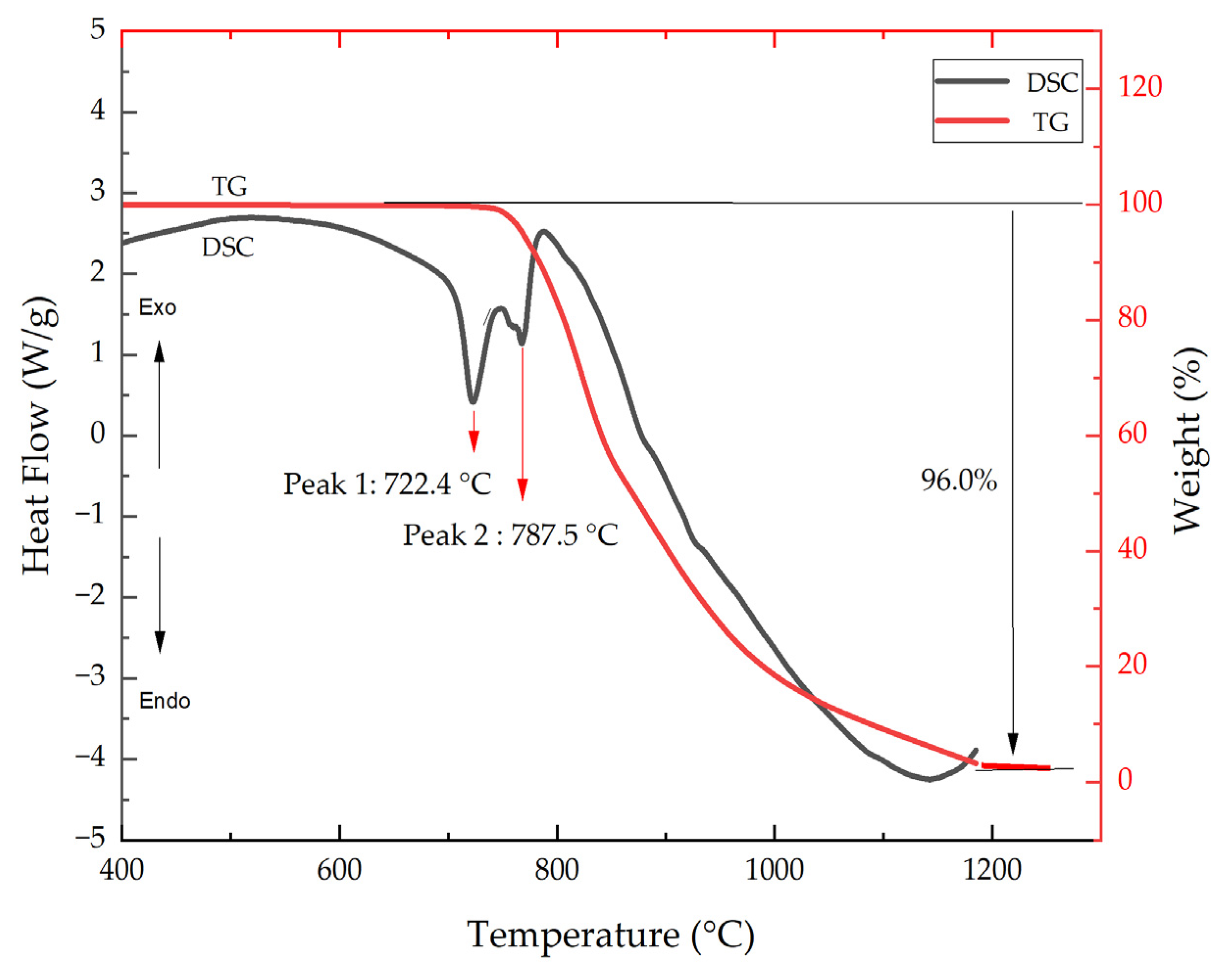
2.1. MoO3 Sublimation Mechanism
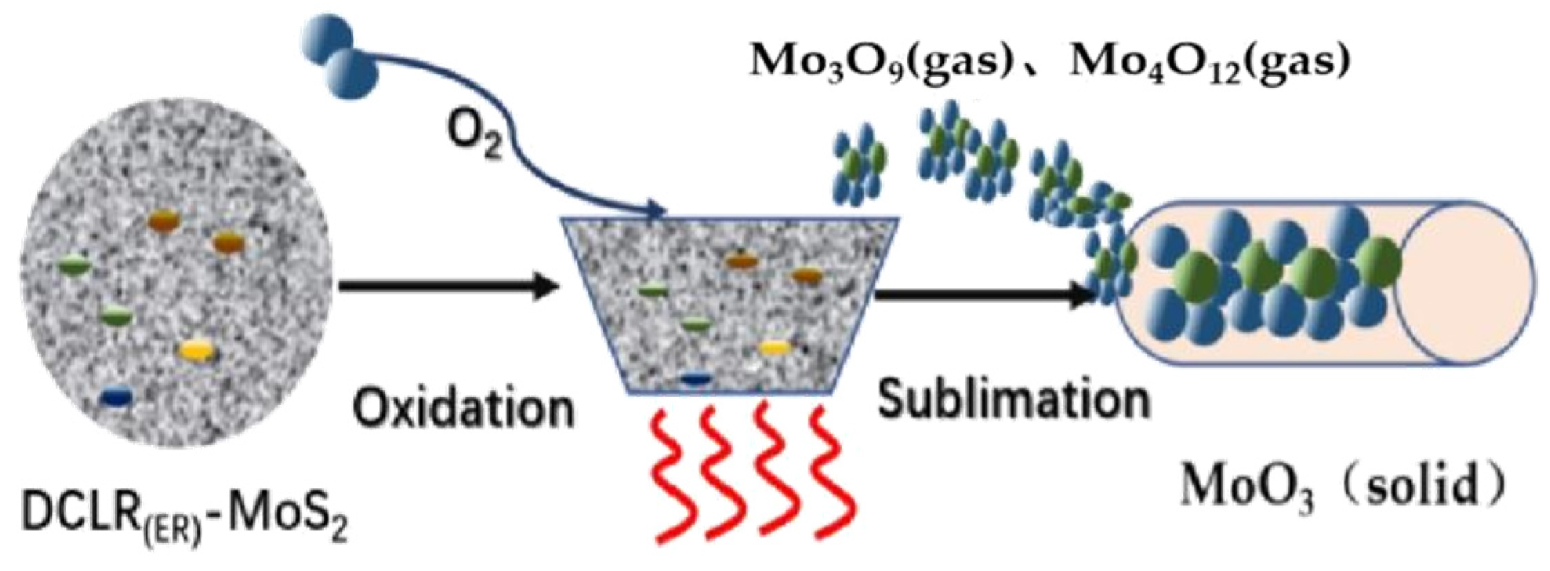
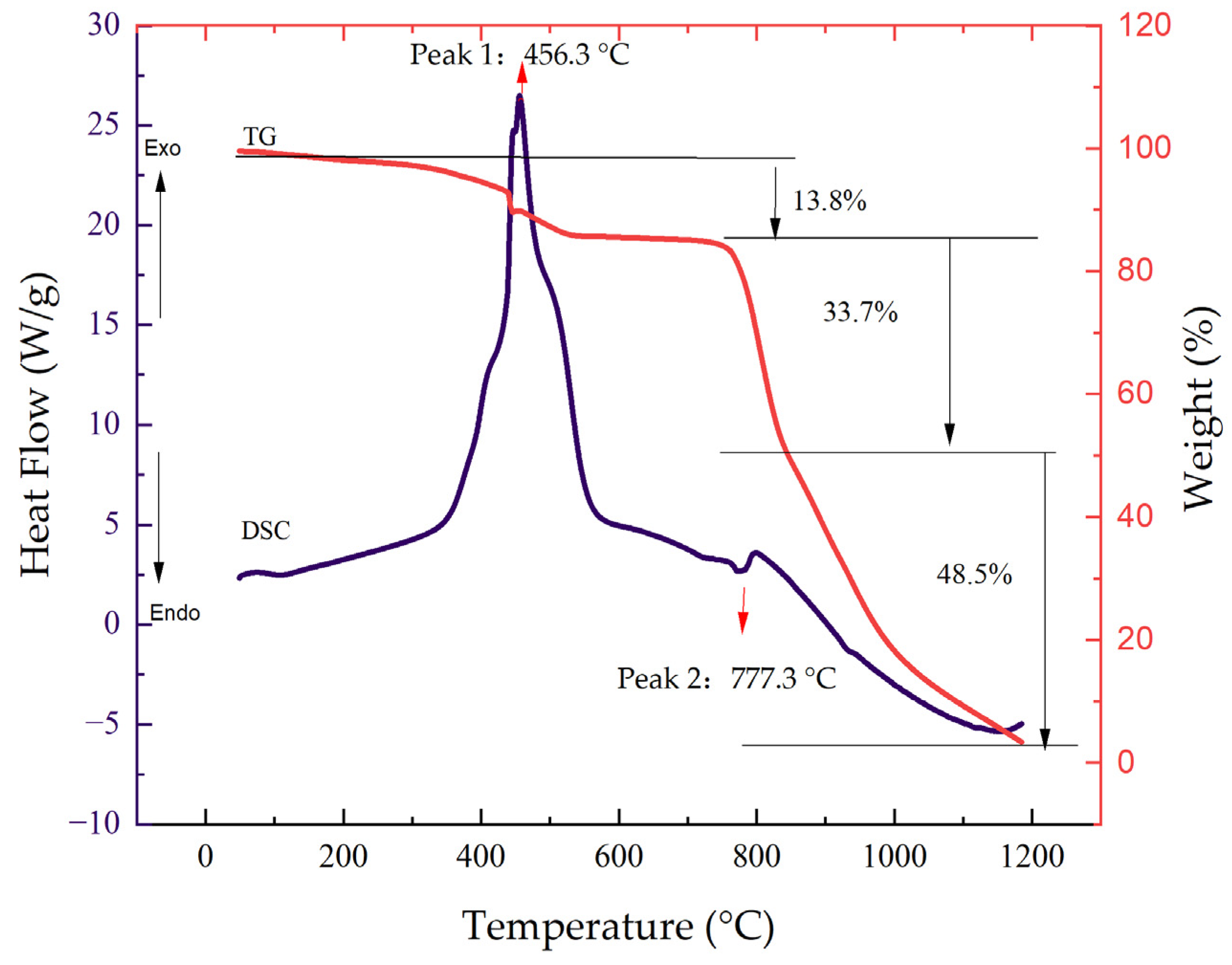
2.2. Mechanism of MoS2 Oxidation
2.3. High-Temperature Reaction Mechanism of DCLR(ER)-MoO3 System
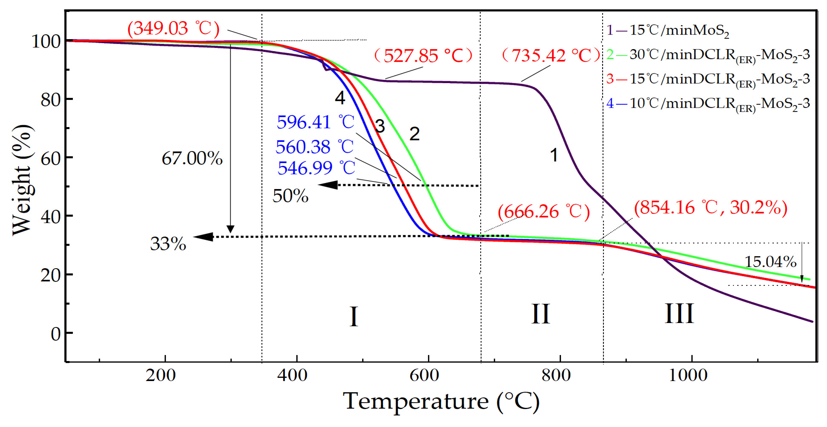
2.4. High-Temperature Reaction Mechanism of DCLR(ER)-MoS2 System
2.5. The Transformation of Molybdenum Catalyst in DCLR(ER)
3. Materials and Methods
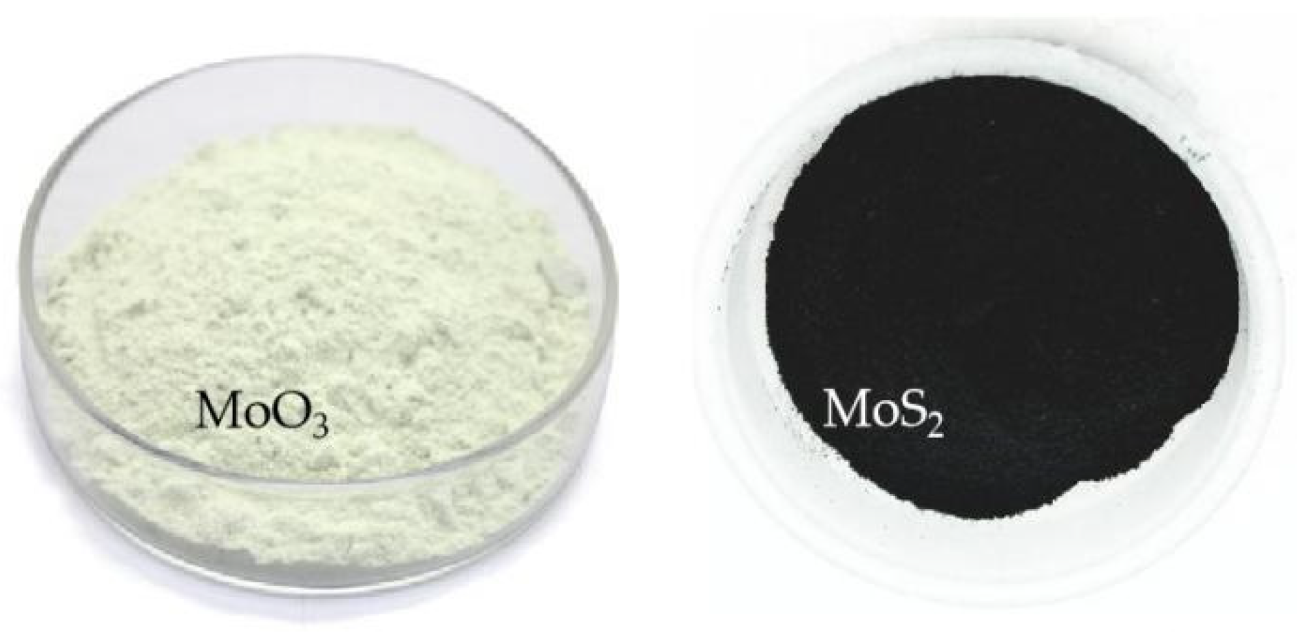
3.1. Experimental Material
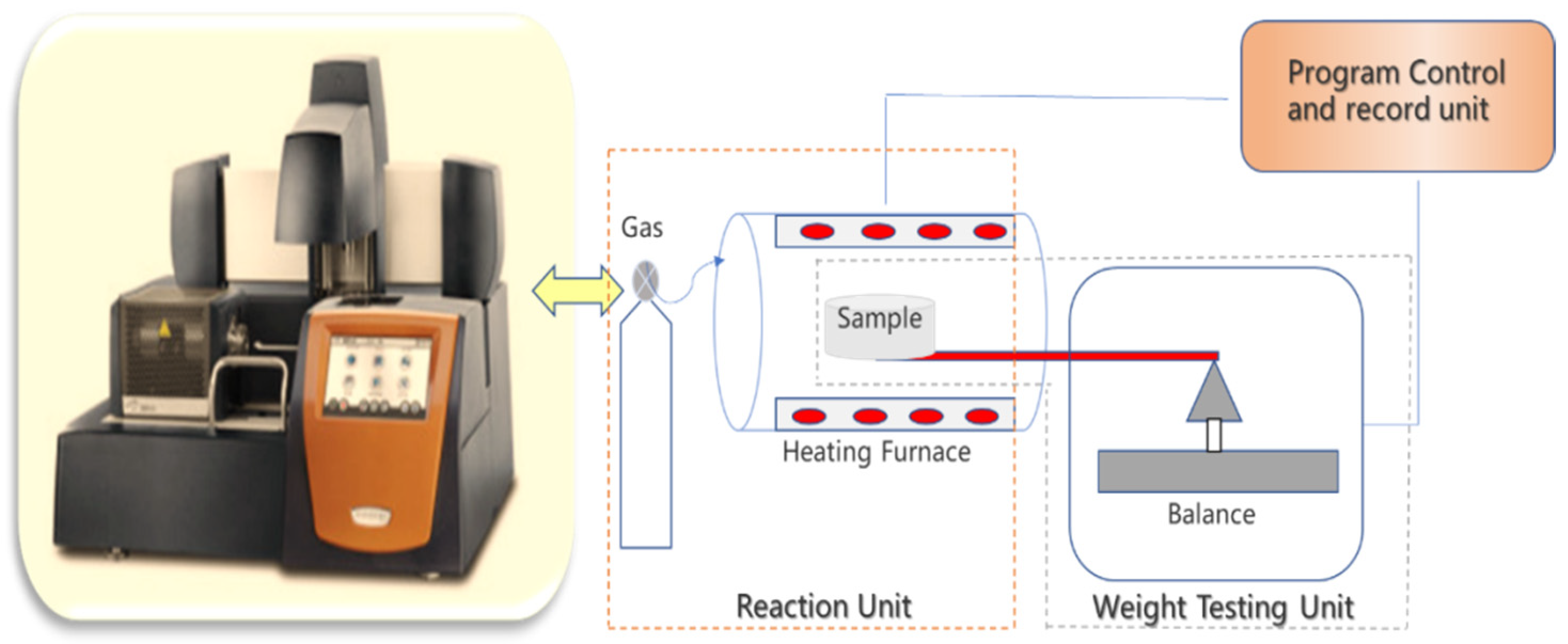
3.2. Experimental Equipment
3.3. Experiment Steps
4. Conclusions
Author Contributions
Funding
Data Availability Statement
Acknowledgments
Conflicts of Interest
References
- Li, X.; Li, J.; Ma, Z.; Bai, Z.-Q.; Zhang, J.; Wu, G.-G.; Li, W. Insight into cross-linking reactions induced by carboxylates in direct coal liquefaction using coal-related model compounds and hydrogen transfer calculation. Fuel 2019, 239, 484–490. [Google Scholar] [CrossRef]
- Shen, T.; Wang, Y.; Liu, Q.; Liu, J.; Liu, Z. A comparative study on direct liquefaction of two coals and hydrogen efficiency to the main products. Fuel Process. Technol. 2021, 217, 106822. [Google Scholar] [CrossRef]
- Ikeda, K.; Sakawaki, K.; Nogami, Y.; Inokuchi, K.; Imada, K. Kinetic evaluation of progress in coal liquefaction in the 1t/d PSU for the NEDOL process. Fuel 2000, 79, 373–378. [Google Scholar] [CrossRef]
- Hou, R.; Bai, Z.; Hao, P.; Dai, X.; Xu, J.; Zheng, H.; Guo, Z.; Kong, L.; Bai, J.; Li, W. Effects of temperature and solvents on structure variation of Yunnan lignite in preheating stage of direct liquefaction. Fuel 2019, 239, 917–925. [Google Scholar] [CrossRef]
- Hou, P.; Zhou, Y.; Guo, W.; Ren, P.; Guo, Q.; Xiang, H.; Li, Y.-W.; Wen, X.-D.; Yang, Y. Rational Design of Hydrogen-Donor Solvents for Direct Coal Liquefaction. Energy Fuels 2018, 32, 4715–4723. [Google Scholar] [CrossRef]
- Xie, K.C.; Wu, C.L. Direct coal liquefaction. In Chemical Industry, 1st ed.; Chemical Industry Press: Beijing, China, 2010; pp. 292–324. [Google Scholar]
- Vasireddy, S.; Morreale, B.; Cugini, A.; Song, C.; Spivey, J.J. Clean liquid fuels from direct coal liquefaction: Chemistry, catalysis, technological status and challenges. Energy Environ. Sci. 2011, 4, 311–345. [Google Scholar] [CrossRef]
- McKee, R.H.; Traul, K.A.; Przygoda, R.T. Evaluation of coal liquids derived from the EDS process in carcinogenesis screening tests. J. Appl. Toxicol. JAT 1995, 15, 159–165. [Google Scholar] [CrossRef] [PubMed]
- Lu, H.; Peng, B.; Ge, Z.; Bai, J.; Kong, L.; Li, H.; Liu, Z.; Bai, Z.; Li, W. The viscosity and crystallization behavior of slag from co-gasification of coal and extraction residue from direct coal liquefaction residue at high temperatures. Fuel 2021, 285, 119119. [Google Scholar] [CrossRef]
- Li, P.; Zong, Z.-M.; Wei, X.-Y.; Wang, Y.-G.; Fan, G.-X. Structural features of liquefaction residue from Shenmu-Fugu subbituminous coal. Fuel 2019, 242, 819–827. [Google Scholar] [CrossRef]
- Lastra, B.; García, R.; Moinelo, S.R. Novel Mo-containing compounds as dispersed catalysts for liquefaction and hydropyrolysis of coals. Energy Fuels 1997, 11, 411–415. [Google Scholar] [CrossRef]
- Hu, H.; Bai, J.; Guo, S.; Chen, G. Coal liquefaction with in situ impregnated Fe2(MoS4)3 bimetallic catalyst. Fuel 2002, 81, 1521–1524. [Google Scholar] [CrossRef]
- Sheng, J.; Baikenov, M.I.; Liang, X.; Rao, X.; Ma, F.; Su, X.; Zhang, Y. Rapid separation and large-scale synthesis of β-FeOOH nanospindles for direct coal liquefaction. Fuel Process. Technol. 2017, 165, 80–86. [Google Scholar] [CrossRef]
- Jing, X.; Geping, S.; Geling, Y.; Shansong, G.; Hongxue, W.; Hanfeng, L.; Yinfei, C. Mo modified Mo-Fe composite catalysts and their catalytic performance in direct coal liquefaction. CIESC J. 2021, 72, 4675–4684. [Google Scholar]
- Renqi, W.; Tiejun, D. Research Progress on recovery of molybdenum from waste catalyst. Met. Mines 2012, 4, 163–207. [Google Scholar]
- Arslanoğlu, H.; Yaraş, A. Recovery of molybdenum, cobalt and nickel from spent hydrodesulphurization catalyst through oxidizing roast followed by sodium persulfate leaching. Sustain. Mater. Technol. 2021, 28, e00286. [Google Scholar] [CrossRef]
- Zhu, Z.; Yang, F.; Liang, Z.; Hua, L. study on recovering valuable metales by treating molybdunum containing waste catalysts using plasma furnace. China Molybdenum Ind. 2003, 27, 14–16. [Google Scholar]
- Liang, H.; Lu, J. Recovery of molybdenum from acid waste liquid containing molybdenum by ion exchange. China Molybdenum Ind. 1999, 23, 48–50. [Google Scholar]
- Kasra-Kermanshahi, R.; Tajer-Mohammad-Ghazvini, P.; Bahrami-Bavani, M. A biotechnological strategy for molybdenum extraction using acidithiobacillus ferrooxidans. Appl. Biochem. Biotechnol. 2021, 193, 884–895. [Google Scholar] [CrossRef]
- Li, X.; Xing, Z. Recovery of molybdenum from acid precipitation mother liquor by extraction. Chinalco 1995, 2, 11–13. [Google Scholar]
- Parhi, P.K.; Misra, P.K. Environmental friendly approach for selective extraction and recovery of molybdenum (Mo) from a sulphate mediated spent Ni-Mo/Al2O3 catalyst baked leach liquor. J. Environ. Manag. 2022, 306, 114474. [Google Scholar] [CrossRef]
- Wu, C.; Luo, Y.; Zhao, K.; Yu, X.; Zhang, X.; Guo, X. Recycling Molybdenum from Direct Coal Liquefaction Residue: A New Approach to Enhance Recycling Efficiency. Catalysts 2020, 10, 306. [Google Scholar] [CrossRef] [Green Version]
- Carstens, T.; Haynes, D.A.; Smith, V.J. Cocrystals: Solution, Mechanochemistry, and Sublimation. Cryst. Growth Des. 2019, 20, 1139–1149. [Google Scholar] [CrossRef]
- Song, J.; Ni, X.; Gao, L.; Zheng, H. Synthesis of metastable h-MoO3 by simple chemical precipitation. Mater. Chem. Phys. 2007, 102, 245–248. [Google Scholar] [CrossRef]
- Berkowitz, J.; Inghram, M.G.; Chupka, W.A. Polymeric Gaseous Species in the Sublimation of Molybdenum Trioxide. J. Chem. Phys. 2004, 26, 842–846. [Google Scholar] [CrossRef]
- Marin, T.; Utigard, T.; Hernandez, C. Roasting Kinetics of Molybdenite Concentrates. Can. Metall. Q. 2009, 48, 73–80. [Google Scholar] [CrossRef]
- Bale, C.W.; Bélisle, E.; Chartrand, P.; Decterov, S.A.; Eriksson, G.; Gheribi, A.E.; Hack, K.; Jung, I.-H.; Kang, Y.-B.; Melançon, J.; et al. FactSage thermochemical software and databases, 2010–2016. Calphad 2016, 54, 35–53. [Google Scholar] [CrossRef] [Green Version]
- The ab Initio Materials Project (aiMP) Compound Database, GTT-Technologies. Available online: https://gtt-technologies.de/data/ (accessed on 14 December 2021).
- The Materials Project. Available online: www.materialsproject.org (accessed on 14 December 2021).


| Reaction Stage | Reaction Process | Weight Loss/% | ||
|---|---|---|---|---|
| DCLR(ER)-MoO3-1 | DCLR(ER)-MoO3-2 | DCLR(ER)-MoO3-3 | ||
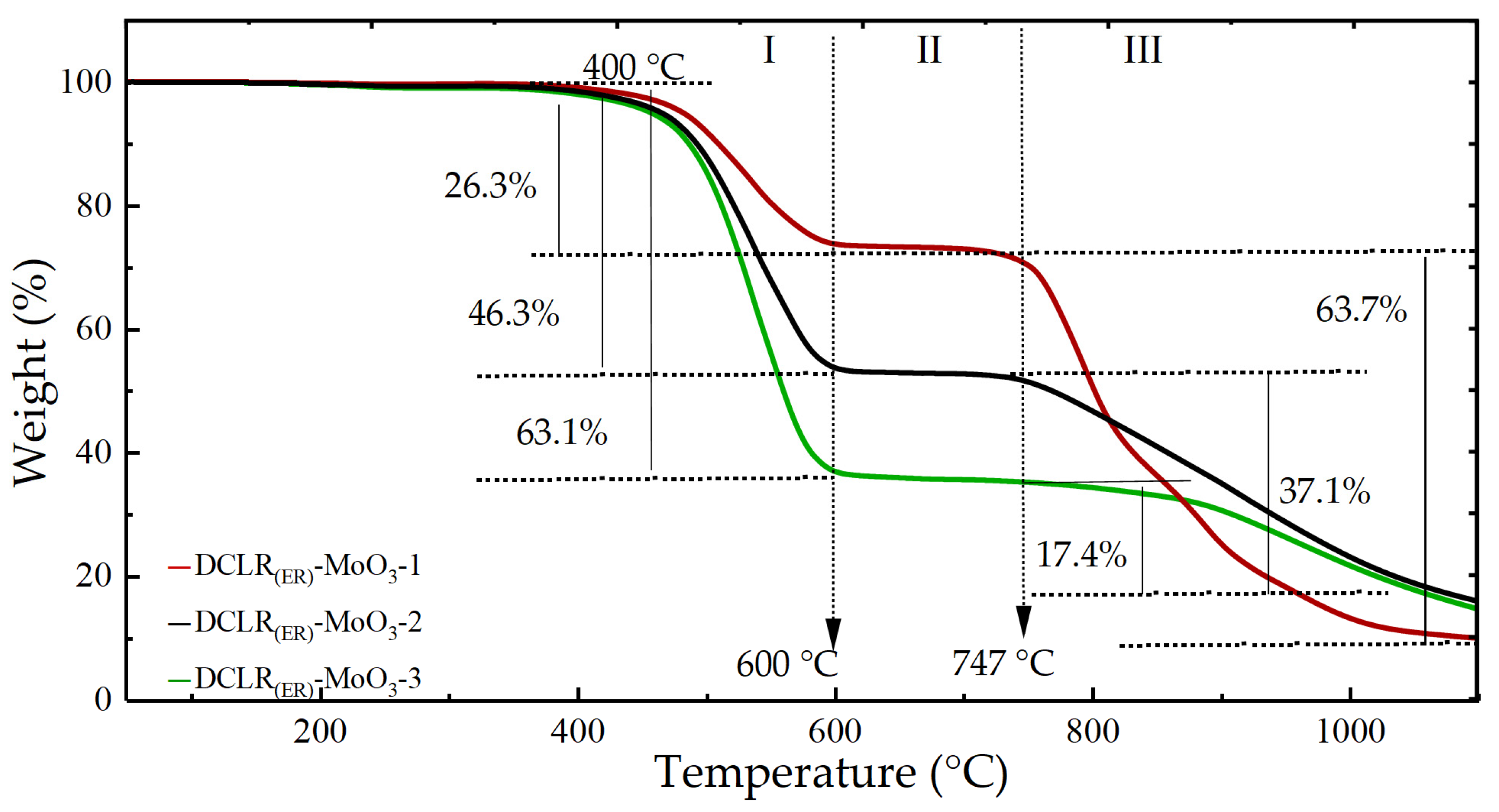
| I (400~600) °C | Pyrolysis of unreacted coal and asphaltene in DCLR(ER) | 26.3 ± 0.4 | 46.3 ± 0.4 | 63.1 ± 0.4 |
| II (600~747) °C | Stable stage | 2.8 ± 0.4 | 2.1 ± 0.4 | 1.8 ± 0.4 |
| III (747~1200) °C | MoO3 sublimation reaction | 60.8 ± 0.4 | 36.8 ± 0.4 | 20.4 ± 0.4 |
| I + II + III (400~1200) °C | DCLR(ER) pyrolysis-MoO3 sublimation | 89.9 ± 0.4 | 85.2 ± 0.4 | 85.3 ± 0.4 |
| Reaction Stage | Reaction Process | Weight Loss/% | ||
|---|---|---|---|---|
| 30 °C/min | 15 °C/min | 10 °C/min | ||
| I (349~606/666) °C | Pyrolysis of unreacted coal and asphaltene in DCLR(ER); molybdenum sulfide oxidation | 67.0 ± 0.4 | 67.0 ± 0.4 | 67.0 ± 0.4 |
| II (606/666~854) °C | MoO3 diffusion | 2.8 ± 0.4 | 3.3 ± 0.4 | 3.3 ± 0.4 |
| III (854~1200) °C | MoO3 sublimation reaction | 12.4 ± 0.4 | 15.04 ± 0.4 | 15.2 ± 0.4 |
| I + II + III (349~1200) °C | DCLR(ER) pyrolysis-MoO3 sublimation | 82.2 ± 0.4 | 85.3 ± 0.4 | 85.5 ± 0.4 |
| Composition | Content/% | Composition | Content/% |
|---|---|---|---|
| SiO2 | 49.74 ± 0.03 | K2O | 1.78 ± 0.02 |
| Al2O3 | 17.33 ± 0.03 | TiO2 | 0.83 ± 0.04 |
| CaO | 17.4 ± 0.02 | MnO | 0.2 ± 0.02 |
| Fe2O3 | 6.3 ± 0.03 | SrO | 0.16 ± 0.01 |
| MgO | 1.78 ± 0.04 | P2O5 | 0.09 ± 0.01 |
| Na2O | 1.88 ± 0.02 | SO3 | 2.19 ± 0.01 |
| Reagent | Chemical Formula | Purity | Melting Point/°C | Boiling Point/°C |
|---|---|---|---|---|
| Nitrogen | N2 | 99.99% | −210 | −196 |
| Oxygen | O2 | 99.99% | −218 | −183 |
| Molybdenum disulfide | MoS2 | A.R. | 2375 | 450 |
| Molybdenum trioxide | MoO3 | A.R. | 795 | 1150 |
| Instrument Name | Instrument Model | Manufacturer | City, Country |
|---|---|---|---|
| Circulating water vacuum pump | SHZ-D | Yuhua Instrument Co. | Gongyi, China |
| Electric blast drying oven | KSD | KangYi electronic instrument factory | Guangzhou, China |
| Constant temperature shaker | THZ-98C | Shanghai Yiheng Co. | Shanghai, China |
| X-ray fluorescence spectrum analyzer | Axios 4400/40 | PANalytical B.V. | Almelo, The Netherlands |
| Synchronous thermal analyzer | TA SDT650 | American TA instrument Co. | New Castle, DE, USA |
| scanning electron microscope | FEI Nova Nano SEM 450 | Thermo Fisher Scientific Co. | Waltham, MA, USA |
| X-ray powder diffractometer | D8 Advance | Bruker AXS | Saarbrücken, Germany |
| Fourier infrared spectrometer | IRPrestige-21 | SHIMADZU Co. | Kyoto, Japan |
| Industrial Analytical Components/% | Elemental Analysis Component/% | ||||
|---|---|---|---|---|---|
| Ad | Cd | Hd | Nd | Sd | |
| 42.3 ± 0.15 | 81.03 ± 0.10 | 4.26 ± 0.11 | 1.03 ± 0.16 | 3.62 ± 0.10 | |
| Composition/% | |||||
| Al2O3 | SiO2 | Fe2O3 | CaO | MoO3 | SO3 |
| 7.38 ± 0.03 | 20.28 ± 0.03 | 28.66 ± 0.03 | 22.76 ± 0.02 | — | 14.01 ± 0.01 |
| DCLR(ER)-Fe/g | MoS2/g | MoO3/g | |
|---|---|---|---|
| MoS2 | 0 | 100 | 0 |
| DCLR(ER)-MoS2-1 | 30 | 70 | 0 |
| DCLR(ER)-MoS2-2 | 50 | 50 | 0 |
| DCLR(ER)-MoS2-3 | 70 | 30 | 0 |
| MoO3 | 0 | 0 | 100 |
| DCLR(ER)-MoO3-1 | 30 | 0 | 70 |
| DCLR(ER)-MoO3-2 | 50 | 0 | 50 |
| DCLR(ER)-MoO3-3 | 70 | 0 | 30 |
| DCLR(ER) | 100 | 0 | 0 |
Publisher’s Note: MDPI stays neutral with regard to jurisdictional claims in published maps and institutional affiliations. |
© 2022 by the authors. Licensee MDPI, Basel, Switzerland. This article is an open access article distributed under the terms and conditions of the Creative Commons Attribution (CC BY) license (https://creativecommons.org/licenses/by/4.0/).
Share and Cite
Wu, C.; Ma, L.; Zhu, Y.; Guo, X.; Wu, Y.; Wu, Z.; Zhang, X.; Hou, L. High-Temperature Reaction Mechanism of Molybdenum Metal in Direct Coal Liquefaction Residue. Catalysts 2022, 12, 926. https://doi.org/10.3390/catal12080926
Wu C, Ma L, Zhu Y, Guo X, Wu Y, Wu Z, Zhang X, Hou L. High-Temperature Reaction Mechanism of Molybdenum Metal in Direct Coal Liquefaction Residue. Catalysts. 2022; 12(8):926. https://doi.org/10.3390/catal12080926
Chicago/Turabian StyleWu, Chunling, Linge Ma, Yufei Zhu, Xuqiang Guo, Yongli Wu, Zhen Wu, Xian Zhang, and Lihua Hou. 2022. "High-Temperature Reaction Mechanism of Molybdenum Metal in Direct Coal Liquefaction Residue" Catalysts 12, no. 8: 926. https://doi.org/10.3390/catal12080926
APA StyleWu, C., Ma, L., Zhu, Y., Guo, X., Wu, Y., Wu, Z., Zhang, X., & Hou, L. (2022). High-Temperature Reaction Mechanism of Molybdenum Metal in Direct Coal Liquefaction Residue. Catalysts, 12(8), 926. https://doi.org/10.3390/catal12080926