Article

Effect of a Metallocene Catalyst Mixture on CNT Yield Using the FC-CVD Process

1
Department of Mechanical and Materials Engineering, University of Cincinnati, Cincinnati, OH 45221, USA
2
Materials Group, Bhabha Atomic Research Centre, Mumbai 400085, India
*
Authors to whom correspondence should be addressed.
Catalysts 2022, 12(3), 287; https://doi.org/10.3390/catal12030287
Submission received: 7 October 2021 / Revised: 24 February 2022 / Accepted: 28 February 2022 / Published: 3 March 2022

Abstract

:
This work studies synthesis of carbon nanotube (CNT) sheet using the high temperature (1400 °C) floating catalyst chemical vapor deposition (FC-CVD) method. Three metallocenes—ferrocene, nickelocene, cobaltocene—and their combinations are used as precursors for metal catalysts in the synthesis process. For the carbon source, an alcohol fuel, a combination of methanol and n-hexane (9:1), is used. First, the metallocenes were dissolved in the alcohol fuel. Then, the fuel mixture was injected into a tube furnace using an ultrasonic atomizer with Ar/H2 carrier gas in a ratio of about 12/1. The synthesis of CNTs from a combination of two or three metallocenes reduces the percentage of metal catalyst impurity in the CNT sheet. However, there is an increase in structural defects in the CNTs when using mixtures of two or three metallocenes as catalysts. Furthermore, the specific electrical conductivity of the CNT sheet was highest when using a mixture of ferrocene and cobaltocene as the catalyst. Overall, the multi-catalyst method described enables tailoring certain properties of the CNT sheet. However, the standard ferrocene catalyst seems most appropriate for large-scale manufacturing at the lowest cost.

1. Introduction

Since the discovery of carbon nanotubes (CNTs) by Iijima in 1991 [1], they have drawn the attention of researchers across the world. The physical and chemical properties of CNTs enable their use in applications including supercapacitors [2,3], patch antennas [4,5], and fiber-reinforced composites [6,7,8,9,10,11], to mention a few among the different industrial, commercial, and defense applications. With the growing list of applications, there is a proportional increase in the global demand for CNTs. As an estimation, the global market value will be about 15 billion US dollars by 2026 [12]. However, the low production rate of CNTs at a reasonable cost is the most important limiting factor in meeting this global demand. Among the three primary methods of CNT production, which are laser ablation [13], chemical vapor deposition (CVD) [14], and arc discharge [15], the CVD method is the most efficient [14] way to meet the estimated global CNT demand. The CVD method can potentially produce high-quality CNT at a large-scale at a comparatively lower cost than the other two methods. The best method for large-scale CNT synthesis is the fluidized bed CVD method [16] although it has limitations. The CNTs produced in the fluidized bed method are in the form of agglomerates or powder and thus are challenging to integrate into different applications. It is very difficult to translate the exotic properties of individual CNTs into a product when powder CNTs are added as fillers to different matrices, such as polymer. The compatibility of the binding element becomes a limitation of powder CNT in many applications. Moreover, loose CNT agglomerates possess a health risk of inhalation, limiting powder CNT use in applications pertaining to human use [17].
In contrast to powder forms of CNT, the floating catalyst CVD (FC-CVD) method produces a self-assembled 3D macrostructure of CNTs with tube length > 1 mm [18]. The long individual CNTs are bound to each other by Van der Waals forces that assist in interweaving the CNTs to form a web of self-assembled CNT directly in the CNT production process. This self-assembled CNT macrostructure can be collected in the form of sheets or yarn during the production stage. Additionally, the Environmental Protection Agency (EPA) of the United States has classified sheets and yarns with long CNTs (made from the FC- CVD method) as “articles” and not “particles,” meaning they are too large to be inhaled or absorbed by the skin [19]. The FC-CVD method has the highest capacity to produce continuous macro-structures of CNTs in the form of sheets or yarn. The FCCVD method has the advantage of being substrate-free; therefore, the process of catalyst preparation, common in substrate growth CVD methods, is eliminated. Moreover, in the FCCVD method, there is a continuous supply of catalysts which helps in the single-step continuous production of macro-structure of CNT sheets or yarn [20,21,22]. Overcoming the challenge of low CNT yield is more important now than ever due to the recent surge in the use of CNTs for textile/wearable applications [23,24,25,26,27,28].
In the synthesis of carbon nanotubes (CNTs) by the FC-CVD method, metal catalyst, sulfur and carbon play an imperative role. For CNT synthesis, the use of transition metals (Fe, Co, Ni) [29,30,31,32] is common because of their high catalytic activity and high carbon diffusion rate through the metal [33]. In the FC-CVD method, metallocenes are typically used as the precursor of metal catalyst in the presence of argon and hydrogen as carrier gasses [33]. Metallocenes are organometallic compounds with central metal ions linked to two cyclopentadienyl anions, one on either side as shown in Figure 1.
Ferrocene, among all other metallocenes (nickelocene, cobaltocene) for CNT synthesis, is highly favored due to its lower cost, lower toxicity, and higher temperature stability [33]. The ferrocene decomposition starts with shedding the hydrogen atom from the cyclopentadiene ring, subsequently breaking the metal-carbon bond to release the metal cation [34,35]. For cobaltocene and nickelocene, the decomposition starts with the scission of metal-cyclopentadiene bond [35]. Therefore, the decomposition of ferrocene occurs at a relatively higher temperature due to the presence of hydrogen in FC-CVD synthesis. In comparison, the decompositions of cobaltocene are not affected by the presence of hydrogen [33,36].
Another crucial factor in FC-CVD is the presence of sulfur during carbon nanotube synthesis. Sulfur reduces the nucleation energy barrier and facilitates the metal catalyst nucleation. The nucleated catalyst acts as a catalytic surface for carbon diffusion resulting in CNT growth at an optimum temperature [33,36,37]. In one synthesis process, the metal catalyst (Fe) undergoes three events while traversing the length of the horizontal tube reactor’s parabolic temperature profile—decomposition and metal particle nucleation, evaporation, and re-nucleation [33]. The ferrocene and sulfur decompose in the vapor phase, leading to nucleation of the metal catalyst particles at temperatures ≥ 1050 °C. The particle nucleation is immediately followed by particle evaporation at around 1200 °C and is maximum at the highest temperature point of the reactor’s temperature profile. As the evaporated gas phase metal catalyst travels downstream in the reactor tube, the re-nucleation of the metal catalyst from the evaporated phase occurs close to the exit. During re-nucleation, the recovery of metal particles from evaporated phase is not 100%. There is a loss of metal catalyst due to re-nucleation on the reactor tube wall and diffusion [36,37]. During the nucleation and re-nucleation events, particle coagulation exists driven by Brownian motion [38]. In the second nucleation zone, the catalyst particle grows in size due to particle agglomeration driven by particle-particle collision and the collision frequency following classical Smoluchowski theory [37,38,39,40,41]. The CNT growth and aerogel formation zone coincide with the re-nucleation zone. The bulk of the CNT aerogel forms near the exit of the reactor tube, where the temperature follows the downward trend of the parabolic temperature profile. In this low-temperature region, the majority of the impurities get incorporated into the final CNT product. Primarily, the impurities comprise amorphous carbon and Fe catalyst residue [33,36,37,38,39,40,41,42,43]. The amorphous carbon byproducts result from the pyrolytic decomposition of the hydrocarbon [42]. The Fe catalyst particles on which CNT fails to grow get trapped in the long CNT web, resulting in a CNT product with high metal catalyst impurity content. The reason for the failure of the CNT growth on the catalyst particles is yet to be answered [44].
The increase in the Fe catalyst residue in the carbon nanotube final product increases with; the increase in catalyst concentration in the reactor [39], increase in the synthesis temperature [41], and decrease in carrier gas flow rate [44]. It should be noted that less than 0.1% of the supplied Fe catalyst contributes toward CNT growth [45] and the currently achieved carbon efficiency is 1–4% (carbon efficiency is the ratio of the molar production of carbon in the CNT aerogel product to the rate of total molar carbon supplied into the reactor tube from hydrocarbon source) [46]. Therefore, the CNT yield cannot be increased just by increasing the Fe catalyst supply. Controlling the formation of Fe catalyst and chemical dynamics is a key factor for increasing the CNT yield, number of CNT walls, diameter, chirality, and structural defects. More research attention is required to understand the particle dynamics of the synthesis process close to the reactor exit.
Mixing two metal catalysts has shown an increase in CNT yield for the substrate-assisted CVD method [47,48,49,50]. However, there are limited publications available in the literature where cobaltocene [51,52] or nickelocene or their combination [51,52,53,54,55] are used for the synthesis of CNT aerogel from the FC-CVD method.
Ahmad et al. [51] synthesized SWCNTs on bimetallic and trimetallic catalysts from a vertical tube FC-CVD reactor at 1050 °C. The catalysts Fe, Co, Ni, Co-Ni, and Co-Fe were prepared using spark discharge generator, and ethylene was used for the carbon source. The catalytic activity of the Ni catalyst was observed to be poor for SWCNT synthesis. A higher fraction of semiconducting SWCNTs were produced from the Co-Ni catalyst than from Fe and Co as catalysts.
Syntheses of CNT aerogel at 1150 °C using different ratios of ferrocene, nickelocene, and cobaltocene were studied [52]. Carbon nanotube production increased significantly using a mixture of metallocene (Fe1−x−yCoxNiy)(C5H5)2. The production increased when the nickelocene ratio was varied between 25% and 50% in a catalyst mixture of ferrocene and nickelocene. There was no significant change in the Raman spectra from the samples produced using metallocene mixture. Long monocrystalline metal kernels filling the carbon nanotubes due to the capillary effect were observed. However, there was a reduction in electrical resistivity in samples produced from mixing metallocene.
In [53], SWCNTs were synthesized from the vertical tube FC-CVD method at 1200 °C. Ferrocene and nickelocene were used catalyst precursors to synthesize CNTs from an acetone carbon source. It is reported the bimetallic catalyst (Fe-Ni) showed higher reactivity in decomposing acetone than a monometallic catalyst (Fe). However, it is reported that the IG/ID ratio decreased with use of bimetallic catalyst (Fe-Ni) compared to monometallic catalyst (Fe).
Mayne et. Al., in their work [54], produced powder CNTs by the pyrolysis of benzene on ferrocene, nickelocene, or their combination as a catalyst precursor. The synthesis was carried out in a substrate assisted horizontal tube FC-CVD reactor operating between 800 °C and 950 °C. Using a metallocene mixture resulted in higher nanotube yield of aligned carbon nanotubes.
Yang et al. [55] synthesized Fe, Ni, and alloyed Fe-Ni filled carbon nanotubes on ferrocene, nickelocene, or their combination as a catalyst precursor and a mixture of dichlorobenzene (DCB) and xylene as a carbon source. A substrate assisted horizontal tube furnace FC-CVD reactor operating at 800 °C was used for the metal filled CNT synthesis. CNTs produced from 100% ferrocene as the metal catalyst precursor showed a higher filling efficiency (metal kernels filling the nanotubes) than CNTs produced from nickelocene. Additionally, all the samples showed similar ID/IG ratios obtained from Raman spectra.
Analysis of the literature [47,48,49,50,51,52,53,54,55] shows that depending on the condition of the synthesis, the CNT product changes. Most of the summarized work used vertical tube FC-CVD reactors operating at a temperature range of 800–1200 °C. The published work reports an increase in CNT production with the use of a multi-metallic catalyst system.
In this work, we investigate the effect of using a mixture of ferrocene, nickelocene, and cobaltocene catalysts coexisting in fuel to synthesize CNTs at high temperature (1400 °C) by the FC-CVD method. The synthesis of CNTs from a bi-metallic catalyst has a substantial effect on the chirality of CNTs depending on the metal combination used [47,48,56,57]. Using a combination of metallocene for CNT synthesis in a horizontal tube, the FC-CVD method at a temperature of 1400 °C is an important study topic. To our knowledge, horizontal tube FC-CVD synthesis of CNT using a metallocene mixture at a high temperature of 1400 °C has not been studied. Here we show continuous synthesis of the aerogel-like sock by mixing two and three metal catalysts in the fuel, along with the effect of using a metallocene mixture on the CNT yield.

2. Experimental Part

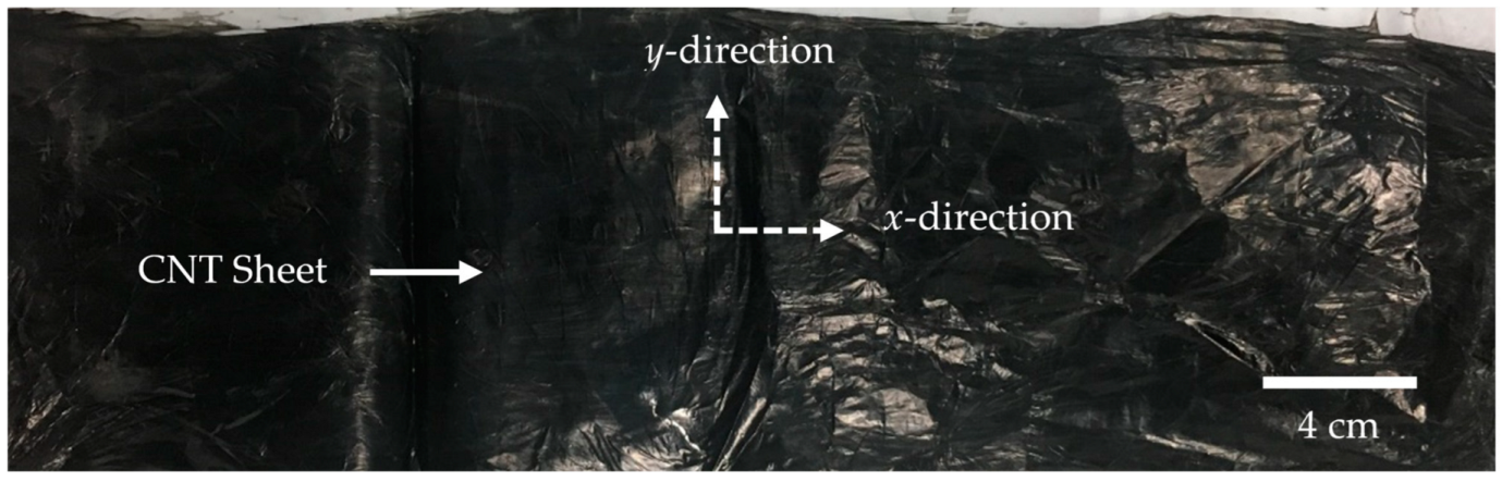
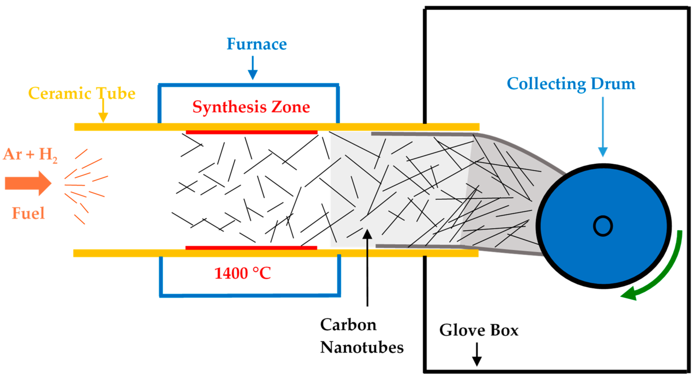
2.1. Carbon Nanotube Sheet Synthesis

The floating catalyst method uses the pyrolysis process for (CNT) synthesis. In this process, there is an injection of feedstock/fuel from one end of the ceramic tube furnace and the synthesized CNT aerogel-like sock collected at the other end in the form of sheet or yarn, as shown in Figure 2.
The single heating zone floating catalyst gas phase CVD reactor is comprised of a horizontally oriented alumina tube of 5 cm outer diameter and 1 m long. With the fuel atomizer, fine droplets of fuel are injected at the intel of the reactor tube. A gas mixture of hydrogen and argon is used to carry the atomized fuel into the reactor maintained at high temperature. The fuel cracks and produces carbon fragments that dissolve in the Fe catalyst to nucleate CNTs. A winding drum collects the aerogel-like CNT sock at the outlet to form CNT sheet. More details on the synthesis process can be found in our previous work [41]. In the current paper, the CNT sheet is synthesized by mixing metallocenes (Ferrocene, Nickelocene, and Cobaltocene; Sigma-Aldrich, St. Louis, MO, USA) into the fuel of methanol (90 vol%, Fisher Scientific, Waltham, MA, USA), n-hexane (10 vol%, Fisher Scientific, Waltham, MA, USA), and thiophene (Sigma Aldrich). As there is debate on the role of sulfur in controlling the size of the metal catalyst particles after the re-nucleation event [36,58], the catalyst/S ratio is kept constant for all four fuels. Table 1 presents the summary of the composition of all the fuels prepared by mixing the three metallocenes in a 100 mL mixture of methanol and n-hexane in a 9:1 ratio with thiophene for the fuel used for this experiment.
A mixture of hydrogen and argon is used as a carrier gas with flow rates of 200 SCCM and 2000 SCCM, respectively. The fuel injection rate is 20 mL h−1, along with the synthesis temperature maintained at 1400 °C throughout the experiment. The experiment was conducted for 30 min for each of the fuel types. Three samples for each of the fuel are collected over a period of three days in a randomized order.

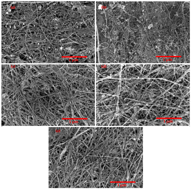
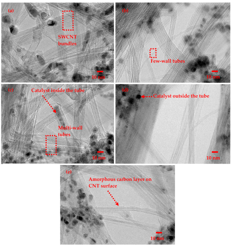
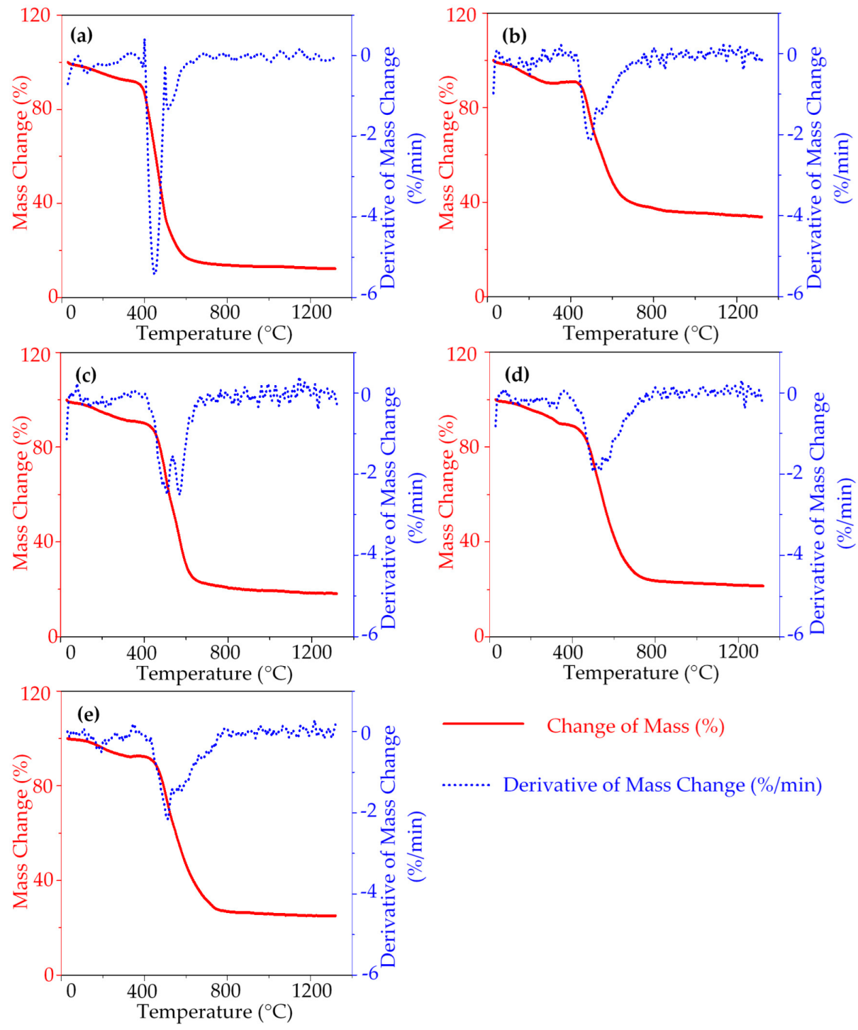
2.2. Characterization

The collected CNT sheets were characterized using a SCIOS dual-beam scanning electron microscope (SEM)/focused ion beam (FIB) equipped with EDX for elemental analysis and high-resolution imaging. The EDX analysis is a qualitative surface analysis and does not give reliable bulk information on the CNT sheet. Moreover, an FEI CM-20 transmission electron microscope (TEM) is used for nanotube structural characterization. X-ray diffraction (XRD) is performed on the CNT sheets from 10° to 80° (2θ) at a scan rate of 0.95°/step with 0.02° step size (Philips X’Pert Pro PW3040, PANalytical, ALMELO, Netherlands). The CNT samples were also studied using a Renishaw via Raman spectroscopy, with an argon laser of 514 nm wavelength and an R-type laser of 785 nm wavelength. The collection of Raman data is from >10 spots on each of the CNT samples. A Netzsch STA409 thermal gravimetric analysis (TGA) analyzer is used to characterize the thermal degradation. For TG analysis, CNT sheets of mass between 3 mg and 4.5 mg are heated up from room temperature to 1300 °C at a rate of 5 °C min−1 in 100 mL min−1 of air. Electrical conductivity is measured using a square four-probe system [21].

2.3. Calculation

For statistical analysis, all the numerical data sets are tested with an analysis of variance (ANOVA) test at a significance level of 0.05. Moreover, the means are compared based on the Tukey test at a 0.05 significance level. Standard deviation is used for the error bar. The IG/ID ratio from the Raman spectra takes an average of > 10 scans at different spots. The yield of CNT is an important parameter which is required for the commercialization of CNT. Higher yield of CNT will reduce the cost of CNT material and help in meeting the demand for a wide variety of engineering applications. Therefore, the definition of CNT yield and its estimation is important.
Yield rate: This is defined as the quantity of the CNT produced per hour (g/h). For this measurement, the synthesized sock per hour M sock is weighed in units of g/h. Then the CNT mass percentage m CNT in the sock is determined from TGA along with the catalyst mass percentage m catalyst and amorphous carbon mass percentage m amorphous . The quantity of CNT produced per hour, the yield rate Y CNT of the sock, is estimated in units of g/h with the help of the CNT mass percentage m CNT estimation as follows:
m CNT ( wt . % ) = m total ( m amorphous + m catalyst ) m total × 100
Here, m total is the mass of the sample at the start of the TGA measurement, m amorphous is the mass of sample burnt till 400 °C which is the mass of the amorphous carbon, and m catalyst is the mass of the residue at the end of the TGA measurement.
Y CNT ( g / h ) = m CNT 100 × M sock
Carbon Conversion: This is found by dividing the yield rate by the grams of carbon supplied in the reactor per hour C supp .
C conv ( % ) = Y CNT C supp × 100
The calculation for the C supp per hour from 20 mL fuel is available in Appendix A.

3. Result and Discussion

The synthesized CNT sample from one of the fuels is shown in Figure 3.
The synthesized CNT aerogel was directly collected on a rotating drum covered with Teflon sheet and densified with ethanol to facilitate CNT sheet manufacturing. The CNT sheet collection is parallel to the gas flow direction (x-direction), making the CNTs more aligned in the x-direction than the y-direction. The higher alignment of the CNTs in one direction causes the macrostructure of the CNT sheet to have anisotropic properties.
Analyzing the scanning electron microscope (SEM) images helped in understanding the surface morphology of the synthesized CNT sheets samples from the five different fuel types. Figure 4a–e shows the surface morphology of the CNT samples produced from Fuels I–V, respectively.
Comparing Figure 4a,b, visibly there is an increase in impurity on the CNT surface with the increase in ferrocene mass in Fuel II (Fe-100%) from 0.7 g to 1.3 g compared to Fuel I (Fe~54%). The high impurity is primarily because of a metal catalyst residue on which the CNT failed to nucleate, and the Fe catalyst ends up in the final CNT product. These carbon encapsulated metal catalyst residues are seen in the TEM images (Figure 5). The CNT samples produced from multi-catalyst fuel, i.e., Fuel III (Fe: Ni~54:46), Fuel IV (Fe-Co~54:46), and Fuel V (Fe:Ni: Co~54:23:23) (Figure 4c–e), show comparatively a lower amount of catalyst residue deposition on the CNT surface than the samples produced from the ferrocene only fuels. The three fuels have identical catalyst concentrations and catalyst/S ratio as Fuel I, except for having more than one metal catalyst mixed in the fuel.
The transmission electron microscope (TEM) images (Figure 5) give a closer look at individual CNTs present in the samples. The primary use of TEM images is for identification of multi-wall CNT (MWCNT), single-wall CNT (SWCNT), double-wall CNT (DWCNT), few-wall CNT (FWCNT), deposition of the amorphous carbon layer on the CNTs, and catalyst particles.
From the TEM images, it is apparent that the samples from the five fuels are comprised of both single-wall CNTs and multi-wall CNTs. There is deposition of amorphous carbon on the surface of the CNTs for all the samples. The catalyst particles which failed to nucleate CNTs can be seen covered with an amorphous layer of carbon. Generally, catalyst particles along with amorphous carbon constitute impurity in the CNT sheets. We estimate the impurity levels in the CNT sheet samples with TGA analysis. The TGA curves are shown in Figure 6.
Thermogravimetric (TGA) analysis of the synthesized samples helps to evaluate the impurity levels and percentage of CNT in the sheet. All catalyst particles along with amorphous carbon constitute impurities in the CNT sheets. Currently, we do not have a way to quantify the amount of catalyst that nucleated into CNTs separately, and the amount of catalyst that failed to do so because the residual metal catalyst at the end of TG analysis is comprised of the catalyst that nucleated CNT as well as the catalyst that failed to do so.
Oxidation events at different temperatures for different samples are observable from the TGA curves in Figure 6. Amorphous carbon and the volatile hydrocarbon content of the CNT samples burns out first around ~450 °C. The burning of the CNT content of the sample follows until ~800 °C; beyond ~800 °C, the residual mass comprises a metal catalyst. There is no noticeable mass increase beyond ~800 °C due to the oxidation of the metal catalyst into metal oxide.
The burning event for CNTs from ~450 °C to ~800 °C comprises the oxidation of single-wall, double-wall, few-wall, and multi-wall CNTs. The SWCNTs are highly reactive and hence oxidize at lower temperatures [41,59]. Comparatively, the MWCNTs require higher energy to oxidize. However, estimating the mass percentage of single-wall CNTs and multi-wall in the samples is difficult because of the overlapping of different oxidation events [41,45]. The presence of a broad DTG curve for all the samples indicates the presence of CNTs with one and more than one wall in the samples [45]. This is also observable from the TEM images (Figure 5).
It is observed that there is an insignificant difference in amorphous carbon content in the samples. The presence of amorphous carbon is attributed to the carbon source used for the experiment [33], which is the same for all five fuels. It is evaluated that with a high concentration of the ferrocene as in Fuel II (Fe-100%), there is a high residual metal catalyst mass (Figure 7).
The SEM image (Figure 4b) for Fuel II (Fe-100%) supports the high metal catalyst impurity in the CNT sheet. It is observed that samples from Fuels III (Fe: Ni~54:46), IV (Fe: Co~54:46), and V (Fe: Ni: Co~54:23:23) have significantly less residual metal catalyst than Fuel II (Fe-100%), despite having the same catalyst concentration and catalyst/S ratio. The higher mass percent of the residual metal catalyst in the CNT sample from Fuel II (Fe-100%) represents a high metal catalyst agglomeration and non-participation of the catalyst in CNT growth. In substrate growth CVD methods, when two different metal catalyst systems are used, there is inhibition of catalyst particle growth due to a lack of catalyst sintering [49,60,61,62]. Loebick et al. used Mn and Co bi-metallic catalyst on a silica substrate for SWCNT synthesis [60]. Their work reported that the highly dispersed Mn ions in the silica substrate act as an anchoring site for small Co particles, preventing them from sintering into large catalyst particles. It is observed for Fuel III (Fe: Ni~54:46), Fuel IV (Fe: Co~54:46), and Fuel V (Fe: Ni: Co~54:23:23) that mixing different CNT catalyzing metallocenes in the fuel may hinder the agglomeration of catalyst particles hence decreasing the metal catalyst residue in the samples.
The calculated yield rate using Equation (2) is shown in Figure 8.
Based on the yield rate calculation results as shown in Figure 8, it is evident that there is no significant difference in yield rate among the five fuels. From this, we can say that mixing metallocenes reduces the catalyst residue in the sample due to lack of catalyst agglomeration, but there is no significant increase in the production of CNTs per hour. Figure 9 shows the effect of five fuels on carbon conversion.
The average carbon conversion for all five fuel samples is significantly different, with the highest Fuel IV (Fe: Co~54:46). The lack of particle agglomeration might have contributed to improved carbon conversion. Among Fuel III (Fe: Ni~54:46), Fuel IV (Fe: Co~54:46), and Fuel V (Fe: Ni: Co~54:23:23), Fuel IV (Fe: Co~54:46) has the highest carbon conversion. The carbon affinity of Fe, Ni, and Co is in the order Fe > Co > Ni [63]. We speculate that the better carbon affinity of cobalt and lack of catalyst agglomeration may have contributed to the highest carbon conversion for Fuel IV (Fe: Co~54:46). However, the improvement in the carbon conversion is not realized in a higher CNT yield rate due to the random variation and uncontrolled parameters in the operation of the FC-CVD reactor. Comparing the cost of ferrocene (USD 38.30/100 g, source Sigma Aldrich) and cobaltocene (USD 4140/100 g, source Sigma Aldrich), there is a 108-times increase in metallocene cost. Therefore, the slight improvement in carbon conversion is not commercially advantageous for large-scale CNT production. A maximum of 3.83% of the supplied carbon contributes to CNT production. A minimal amount of the supplied carbon deposits on the CNT surface are amorphous carbon, along with some deposits on the reactor wall (shown in Figure 10). The rest of the supplied carbon leaves the reactor in some gas compound form.
X-ray diffraction spectra are used here to identify the unknown crystalline material in the CNT samples. The mentioned cards, along with data, can be referred to for information on the crystal structure. There is some alloying of the metal catalyst in the synthesized samples, which is observable from X-ray diffraction spectra (Figure 11).
For the samples synthesized from Fuel III (Fe: Ni~54:46), Fuel IV (Fe: Co~54:46), and Fuel V (Fe: Ni: Co~54:23:23), the data show the presence of taenite (an alloy of Fe and Ni), CoFe, and taenite + CoFe, respectively (Figure 11b–d). The presence of metal alloys in the samples is promising for making CNT-metal composite samples. Nanoparticle coalescence into larger particles is driven by nanoparticle size, nanoparticle size distribution, melting point, coalescence time, pressure, and surface energy [64,65,66,67]. Lehtinen et al. indicate that reduced surface energy of nanoparticles is the driving force for coalescence of nanoparticles. It is speculated that presence of Ni and Co, along with Fe in Fuel III (Fe: Ni~54:46), Fuel IV (Fe: Co~54:46), and Fuel V (Fe:Ni: Co~54:23:23), alters the surface energy and hinders coalescence of nanoparticles to larger particles compared to Fuel II (Fe-100%). The difference in the melting point of metals in use (Fe, Ni, and Co) can contribute to the lack of agglomeration of metal catalyst in the samples. Further studies on particle coalescence in the presence of hydrogen and sulfur will explain the agglomeration kinetics, resulting in the less residual metal catalyst for Fuel III (Fe: Ni~54:46), Fuel IV (Fe: Co~54:46), and Fuel V (Fe: Ni: Co~54:23:23).
From the Raman spectroscopy analysis of the samples, the presence of single-wall CNT is evident from radial breathing mode (RBM)-peaks (Figure 8c). However, as far as the inner diameter of the CNTs is <2 nm, there are RBM peaks from any (SWCNT, DWCNT, FWCNT, and MWCNT) CNT material [68]. The CNTs in the samples are a combination of single-wall CNTs, double-wall CNTs, few-wall CNTs, and multi-wall CNTs. The TEM images (Figure 5) and the multiple oxidation events at different temperatures in the range of ~450 °C to ~800 °C in TG analysis further corroborate the presence of different number of walls in the CNTs produced.
Figure 12d shows the G-peak ratio to disorder-induced D-peak (IG/ID) for the samples for 785 nm and 514 nm lasers. The supply of different metal catalysts increases the defects of the CNT structure for two metallocenes (Fuel III (Fe: Ni~54:46) and Fuel IV (Fe: Co~54:46)) and three metallocenes (Fuel V (Fe: Ni: Co~54:23:23)) mixture at the same catalyst concentration compared to a single metallocene in fuel. The solubility of carbon is different for each of the transition metals and their alloys [63,69]. Fundamentally, the growth process of CNTs involves the dissolution of carbon in the liquid metal phase of the catalyst surface and subsequent precipitation of the carbon into carbon nanotubes. The precipitation of carbon into carbon nanotubes is a thermodynamic effect due to the increase of carbon concentration in the surface liquid metal phase and crystallization of the metal catalyst core [44,70]. As carbon has the highest affinity towards Fe at high temperatures among the transition metals, it is the most common metal used for floating catalyst gas phase CVD system to synthesize rope-like CNTs. The long strands of CNT produced using the iron-based catalyst entangle with each other due to weak Van der Waals force, which facilitates the formation of the aerogel sock-like structure of CNTs. The formation of the aerogel sock-like structure of the CNTs (called a sock) is unique for continuous CNT collection and mass production. Our initial experiment failed to produce an aerogel sock-like structure of CNTs using 100% nickelocene as a metal catalyst precursor.
The instability of nickelocene at high temperatures has an effect on the process of carbon dissolution into the metal-liquid phase and subsequent precipitation of carbon into CNTs [71]. The CNT samples from the nickel-containing fuels (Fuel III (Fe: Ni~54:46) and Fuel V (Fe: Ni: Co~54:23:23)) show a relative increase in CNT structural defects (decrease in IG/ID, Figure 12d). Moreover, the carbon affinity in the transition metal catalysts used for this study is in the order Fe > Co > Ni [63]. Due to catalyst alloying, CNTs with more structural defects are produced multi-metallocene fuel than the fuel with 100% Fe in the FC-CVD process. The specific electrical conductivities in the x-direction (represents the direction of gas flow in the CNT synthesis process) and y-direction (perpendicular to the gas flow) for different fuel samples are shown in Figure 13 The specific electrical conductivity is maximum in the CNT alignment direction (x-direction).
The increase of catalyst residue deposition on the CNT surface increases the contact resistance between two individual CNTs. With reduced catalyst impurity, the specific electrical conductivity of the material increases.
The use of bimetallic catalyst is reported to favor chiral specific CNT growth [49,50,60,62,72,73,74,75]. The chirality of the CNT determines whether the CNT is a semiconducting type or metallic type. Identifying the semiconducting or metallic CNT and estimating their amount in the CNT bundles is a challenging ongoing research field [61]. There is no study currently available for producing CNT by floating catalyst CVD method at high temperature (1400 °C) using the mixture of ferrocene and cobaltocene under similar synthesis conditions.
The effect of nickelocene instability at high temperature and low carbon affinity towards nickel can have caused the low specific conductivity for samples from Fuel III (Fe: Ni~54:46) and Fuel V (Fe: Ni: Co~54:23:23).

4. Conclusions

This study shows that the catalyst residue impurity decreases by mixing different CNT catalyzing metallocenes through the high-temperature FC-CVD method. Catalyst agglomeration is reduced by combining two metallocenes and three metallocenes in the fuel, reducing the catalyst residue impurity in the synthesized samples. This contrasts the synthesis condition when a single metallocene at high concentration is used as in Fuel II (Fe-100%). By mixing a different transition metal catalyst, an improvement in carbon conversion is noticed. However, the small improvement in carbon conversion is not commercially advantageous for large-scale CNT production. The presence of less catalyst impurity suppresses the effect of structural defect effects on the specific electrical conductivity. The CNT samples from the catalyst combination of ferrocene and cobaltocene show good electrical properties. This study shows that the synthesis of CNT-metal composites is achievable with a high catalyst concentration by mixing different transition metal catalyst particles in the fuel. However, the deposition on the reactor wall reduces the yield of the process and complicates understanding the effects of using multi-catalyst fuels.

Author Contributions

Conceptualization, D.C. and M.J.S.; methodology, D.C.; software, D.C., A.P. and G.Z.; validation, D.C., M.J.S., V.N.S. and K.D.; formal analysis, D.C., G.Z. and K.D.; investigation, D.C., G.Z., M.J.S., V.N.S. and K.D.; resources, D.C., M.J.S. and V.N.S.; data curation, D.C., A.P. and G.Z..; writing—original draft preparation, D.C.; writing—review and editing, D.C., M.J.S., V.N.S., A.P., G.Z. and K.D.; visualization, D.C. and G.Z.; supervision, D.C.; funding acquisition, D.C. and M.J.S. All authors have read and agreed to the published version of the manuscript.

Funding

This research was partly sponsored by the Office of Naval Research (PM Ignacio Perez) and the UC Accelerator for Commercialization Project (Mr. Greg Bell, Entrepreneur in Residence). This research study was also supported by the National Institute for Occupational Safety and Health through the Pilot Research Project Training Program of the University of Cincinnati Education and Research Center Grant #T42OH008432.

Data Availability Statement

The data presented in this study are available on request from the corresponding author.

Conflicts of Interest

The authors declare no conflict of interest.

Appendix A. Carbon Nanotube Synthesis Experiment

Carbon supplied in the alcohol fuel per hour ( C supp ):
Moles   per   milliliter   ( mol / ml ) = Density   ( g / ml ) Molar   mass   ( g / mol )
Moles   per   gram   ( mol / g ) = 1 Molar   mass   ( g / mol )
No .   of   moles   per   hour   ( mol / h ) = moles   per   milliliter   ( mol / ml ) × liquid   per   hour   ( ml / h )
No .   of   moles   per   hour   ( mol / h ) = moles   per   gram   ( mol / g )   ×   mass   per   hour   ( g / h )
Moles   of   carbon   per   hour   ( mol / h )   = No .   of   moles   per   hour   ( mol / h ) × No .   of   carbon   atoms   in   the   chemical   formula
The following Table A1 shows the calculation of total moles of carbon supplied per hour into the reactor.
Table A1. Calculation of carbon supplied per hour.
MaterialMethanoln-HexaneMetalloceneThiophene
FormulaCH3OHC6H14* Metal(C5H5)2C4H4S
Quantity per hour18 mL/h2 mL/h0.26 g/h0.15 mL/h
Molar mass (g/mol)32.0486.18186.0484.14
Density0.792 (g/mL)0.655 (g/mL)1.11 (g/cm3)1.05 (g/mL)
Moles per milliliter (mol/mL)0.025(mol/mL)0.008(mol/mL)0.005(mol/g)0.012(mol/mL)
No. of moles per hour (mol/h)0.4450.0150.0010.002
Moles of carbon per hour (mol/h)0.4450.0910.0140.007
* Metal = Fe/Co/Ni.
Carbon   supplied   per   hour   ( g / h ) = Total   moles   of   carbon   ( mol / h ) ×   Molar   mass   of   carbon   ( g / mol )
Carbon supplied per hour (g/h) = 0.558 mol/h × 12 g/mol = 6.7 g/h

References

  1. Iijima, S. Helical Microtubules of Graphitic Carbon. Nature 1991, 354, 56–58. [Google Scholar] [CrossRef]
  2. Adusei, P.K.; Gbordzoe, S.; Kanakaraj, S.N.; Hsieh, Y.-Y.; Alvarez, N.T.; Fang, Y.; Johnson, K.; McConnell, C.; Shanov, V. Fabrication and Study of Supercapacitor Electrodes Based on Oxygen Plasma Functionalized Carbon Nanotube Fibers. J. Energy Chem. 2020, 40, 120–131. [Google Scholar] [CrossRef] [Green Version]
  3. Wu, G.; Tan, P.; Wang, D.; Li, Z.; Peng, L.; Hu, Y.; Wang, C.; Zhu, W.; Chen, S.; Chen, W. High-Performance Supercapacitors Based on Electrochemical-Induced Vertical-Aligned Carbon Nanotubes and Polyaniline Nanocomposite Electrodes. Sci. Rep. 2017, 7, 43676. [Google Scholar] [CrossRef] [PubMed] [Green Version]
  4. Keller, S.D.; Zaghloul, A.I.; Shanov, V.; Schulz, M.J.; Mast, D.B.; Alvarez, N.T. Radiation Performance of Polarization Selective Carbon Nanotube Sheet Patch Antennas. IEEE Trans. Antennas Propag. 2014, 62, 48–55. [Google Scholar] [CrossRef]
  5. Amram Bengio, E.; Senic, D.; Taylor, L.W.; Tsentalovich, D.E.; Chen, P.; Holloway, C.L.; Babakhani, A.; Long, C.J.; Novotny, D.R.; Booth, J.C.; et al. High Efficiency Carbon Nanotube Thread Antennas. Appl. Phys. Lett. 2017, 111, 163109. [Google Scholar] [CrossRef]
  6. Chauhan, D.; Hou, G.; Ng, V.; Chaudhary, S.; Paine, M.; Moinuddin, K.; Rabiee, M.; Cahay, M.; Lalley, N.; Shanov, V.; et al. Multifunctional Smart Composites with Integrated Carbon Nanotube Yarn and Sheet. In A Tribute Conference Honoring Daniel Inman; Leo, D.J., Tarazaga, P.A., Eds.; International Society for Optics and Photonics: Bellingham, WA, USA, 2017; Volume 10172, p. 1017205. [Google Scholar]
  7. Zhao, M.; Meng, L.; Ma, L.; Ma, L.; Yang, X.; Huang, Y.; Ryu, J.E.; Shankar, A.; Li, T.; Yan, C.; et al. Layer-by-Layer Grafting CNTs onto Carbon Fibers Surface for Enhancing the Interfacial Properties of Epoxy Resin Composites. Compos. Sci. Technol. 2018, 154, 28–36. [Google Scholar] [CrossRef]
  8. Bhanushali, H.; Bradford, P.D. Woven Glass Fiber Composites with Aligned Carbon Nanotube Sheet Interlayers. J. Nanomater. 2016, 2016, 55. [Google Scholar] [CrossRef] [Green Version]
  9. Song, Y.; Chauhan, D.; Hou, G.; Wen, X.; Kattoura, M.; Christine, R.; Vesselin, S. Carbon Nanotube Sheet Reinforced Laminated Composites. In Proceedings of the 31st Annual Technical Conference of the American Society for Composites, Williamsburg, VA, USA, 19–22 September 2016. [Google Scholar]
  10. Xu, C.; Chauhan, D.; Hou, G.; Ng, V.; Song, Y.; Paine, M. Synthesis of Hybrid Carbon Nanotube Yarn and Sheet and Their Applications. In Nanotube Superfiber Materials; William Andrew Publishing: Norwich, NY, USA, 2019; pp. 897–914. ISBN 9780128126677. [Google Scholar]
  11. Gbordzoe, S.; Adusei, P.K.; Chauhan, D.; Alvarez, N.T.; Haase, M.R.; Mansari, K.; Kanakaraj, S.N.; Hsieh, Y.-Y.; Shanov, V. A Simple Two-Step Process for Producing Strong and Aligned Carbon Nanotube-Polymer Composites. C 2019, 5, 35. [Google Scholar] [CrossRef] [Green Version]
  12. Statista. Carbon Nanotubes Global Market Value Forecast 2026. Available online: https://www.statista.com/statistics/714463/global-market-value-of-carbon-nanotubes/ (accessed on 27 August 2019).
  13. Dixit, S.; Shukla, A.K. Raman Studies of Single-Walled Carbon Nanotubes Synthesized by Pulsed Laser Ablation at Room Temperature. Appl. Phys. A 2018, 124, 400. [Google Scholar] [CrossRef]
  14. Liu, Q.; Fang, Y. New Technique of Synthesizing Single-Walled Carbon Nanotubes from Ethanol Using Fluidized-Bed over Fe–Mo/MgO Catalyst. Spectrochim. Acta. A Mol. Biomol. Spectrosc. 2006, 64, 296–300. [Google Scholar] [CrossRef]
  15. Sari, A.H.; Khazali, A.; Parhizgar, S.S. Synthesis and Characterization of Long-CNTs by Electrical Arc Discharge in Deionized Water and NaCl Solution. Int. Nano Lett. 2018, 8, 19–23. [Google Scholar] [CrossRef] [Green Version]
  16. Corrias, M.; Caussat, B.; Ayral, A.; Durand, J.; Kihn, Y.; Kalck, P.; Serp, P. Carbon Nanotubes Produced by Fluidized Bed Catalytic CVD: First Approach of the Process. Chem. Eng. Sci. 2003, 58, 4475–4482. [Google Scholar] [CrossRef]
  17. Öner, D.; Ghosh, M.; Coorens, R.; Bové, H.; Moisse, M.; Lambrechts, D.; Ameloot, M.; Godderis, L.; Hoet, P.H.M. Induction and Recovery of CpG Site Specific Methylation Changes in Human Bronchial Cells after Long-Term Exposure to Carbon Nanotubes and Asbestos. Environ. Int. 2020, 137, 105530. [Google Scholar] [CrossRef] [PubMed]
  18. Schauer, M.W.; White, M.A. Tailoring Industrial Scale CNT Production to Specialty Markets. MRS Online Proc. Libr. 2015, 1752, 103–109. [Google Scholar] [CrossRef]
  19. Nanocomp Technologies|Nanotechnology. Available online: https://www.miralon.com/what-are-carbon-nanotubes (accessed on 25 January 2020).
  20. Chitranshi, M.; Pujari, A.; Ng, V.; Chen, D.; Chauhan, D.; Hudepohl, R.; Saleminik, M.; Kim, S.Y.; Kubley, A.; Shanov, V.; et al. Carbon Nanotube Sheet-Synthesis and Applications. Nanomaterials 2020, 10, 2023. [Google Scholar] [CrossRef]
  21. Chauhan, D. Manufacturing and Applications of Carbon Nanotube Sheet and Thread. Master’s Thesis, University of Cincinnati, Cincinnati, OH, USA, 2018. [Google Scholar]
  22. Hou, G.; Mast, D.; Kleismit, R.; Chauhan, D.; Xu, C.; Dugre, J.; Ng, V.; Turgut, Z.; Chen, R. Industrializing Nanotube Superfiber Materials. In Nanotube Superfiber Materials; William Andrew Publishing: Norwich, NY, USA, 2019; pp. 573–601. ISBN 9780128126677. [Google Scholar]
  23. Kim, M.; Park, Y. High Sensitive CNT Imbedded Knit Fabrics for Heat Comfort. Fibers Polym. 2018, 19, 2112–2120. [Google Scholar] [CrossRef]
  24. Schulz, M.J.; Chauhan, D.; Kanakaraj, S.; Mast, D.; Shanov, V.; Hou, G.; Ng, V.; Xu, C.; Chen, R.D.; Kubley, A.; et al. Carbon Nanotube Hybrid Material Fabric, Composite Fabric, and Personal Protective Apparel and Equipment. U.S. Patent US20200270774A1, 27 August 2020. [Google Scholar]
  25. Chauhan, D.; Xu, C.; Chen, D.; Kubley, A.; Brandewie, B.; Hou, G.; Li, W.; Ng, V.; Rabiee, M.; Cahay, M.; et al. Introduction to Carbon Nanotube Hybrid Textiles. J. Text. Sci. Fash. Technol. 2019, 1, 1–7. [Google Scholar] [CrossRef]
  26. Kubley, A.; Chauhan, D.; Kanakaraj, S.N.; Xu, C.; Chen, R.; Ng, V.; Bell, G.; Verma, P.; Hou, X.; Chitranshi, M.; et al. Smart Textiles and Wearable Technology Innovation with Carbon Nanotube Technology. In Nanotube Superfiber Materials; William Andrew Publishing: Norwich, NY, USA, 2019; pp. 263–311. ISBN 9780128126677. [Google Scholar]
  27. Chitranshi, M.; Chauhan, D.; Kubley, A.; Pujari, A.; Xu, C.; Chen, D.; Chaudhary, S.; Hou, G.; Bell, G.; Brandewie, B.; et al. Pioneering Carbon Nanotube Textile Engineering & Fashion Technology. J. Text. Eng. Fash. Technol. 2019, 5, 89–92. [Google Scholar] [CrossRef]
  28. Chauhan, D.; Chen, R.; Xu, C.; Mast, D.; Kleismit, R.; Kubley, A.; Hou, G.; Chitranshi, M.; Pujari, A.; Devarakonda, S.; et al. Carbon Nanotube Hybrid Fabric and Tape. In Nanotube Superfiber Materials; William Andrew Publishing: Norwich, NY, USA, 2019; pp. 239–261. ISBN 9780128126677. [Google Scholar]
  29. Chen, X.; Zhou, J.; Chen, S.; Zhang, H. Catalytic Performance of M@Ni (M = Fe, Ru, Ir) Core−shell Nanoparticles towards Ammonia Decomposition for COx-Free Hydrogen Production. J. Nanopart. Res. 2018, 20, 148. [Google Scholar] [CrossRef]
  30. Shukrullah, S.; Naz, M.Y.; Mohamed, N.M.; Ibrahim, K.A.; Ghaffar, A.; AbdEl-Salam, N.M. Synthesis of MWCNT Forests with Alumina-Supported Fe2O3 Catalyst by Using a Floating Catalyst Chemical Vapor Deposition Technique. J. Nanomater. 2019, 2019, 1–12. [Google Scholar] [CrossRef]
  31. Fuge, R.; Liebscher, M.; Schröfl, C.; Damm, C.; Eckert, V.; Eibl, M.; Leonhardt, A.; Büchner, B.; Mechtcherine, V. Influence of Different Hydrocarbons on the Height of MWCNT Carpets: Role of Catalyst and Hybridization State of the Carbon Precursor. Diam. Relat. Mater. 2018, 90, 18–25. [Google Scholar] [CrossRef]
  32. Bouanis, F.Z.; Florea, I.; Bouanis, M.; Muller, D.; Nyassi, A.; Le Normand, F.; Pribat, D. Diameter Controlled Growth of SWCNTs Using Ru as Catalyst Precursors Coupled with Atomic Hydrogen Treatment. Chem. Eng. J. 2018, 332, 92–101. [Google Scholar] [CrossRef]
  33. Weller, L.; Smail, F.R.; Elliott, J.A.; Windle, A.H.; Boies, A.M.; Hochgreb, S. Mapping the Parameter Space for Direct-Spun Carbon Nanotube Aerogels. Carbon 2019, 146, 789–812. [Google Scholar] [CrossRef]
  34. Mclean, B.; Kauppinen, E.I.; Page, A.J. Initial Competing Chemical Pathways during Floating Catalyst Chemical Vapor Deposition Carbon Nanotube Growth. J. Appl. Phys. 2021, 129, 44302. [Google Scholar] [CrossRef]
  35. Dyagileva, L.M.; Mar’in, V.P.; Tsyganova, E.I.; Razuvaev, G.A. Reactivity of the First Transition Row Metallocenes in Thermal Decomposition Reaction. J. Organomet. Chem. 1979, 175, 63–72. [Google Scholar] [CrossRef]
  36. Hoecker, C.; Smail, F.; Bajada, M.; Pick, M.; Boies, A. Catalyst Nanoparticle Growth Dynamics and Their Influence on Product Morphology in a CVD Process for Continuous Carbon Nanotube Synthesis. Carbon 2016, 96, 116–124. [Google Scholar] [CrossRef] [Green Version]
  37. Hoecker, C.; Smail, F.; Pick, M.; Weller, L.; Boies, A.M. The Dependence of CNT Aerogel Synthesis on Sulfur-Driven Catalyst Nucleation Processes and a Critical Catalyst Particle Mass Concentration. Sci. Rep. 2017, 7, 14519. [Google Scholar] [CrossRef] [Green Version]
  38. Kuwana, K.; Saito, K. Modeling CVD Synthesis of Carbon Nanotubes: Nanoparticle Formation from Ferrocene. Carbon 2005, 43, 2088–2095. [Google Scholar] [CrossRef]
  39. Gökstorp, F.K.A.; Juniper, M.P. Flow Simulations Including Iron Nanoparticle Nucleation, Growth and Evaporation for Floating Catalyst CNT Production. Catalysts 2020, 10, 1383. [Google Scholar] [CrossRef]
  40. Hoecker, C.; Smail, F.; Pick, M.; Boies, A. The Influence of Carbon Source and Catalyst Nanoparticles on CVD Synthesis of CNT Aerogel. Chem. Eng. J. 2017, 314, 388–395. [Google Scholar] [CrossRef] [Green Version]
  41. Hou, G.; Chauhan, D.; Ng, V.; Xu, C.; Yin, Z.; Paine, M.; Su, R.; Shanov, V.; Mast, D.; Schulz, M.; et al. Gas Phase Pyrolysis Synthesis of Carbon Nanotubes at High Temperature. Mater. Des. 2017, 132, 112–118. [Google Scholar] [CrossRef]
  42. Gspann, T.S.; Smail, F.R.; Windle, A.H. Spinning of Carbon Nanotube Fibres Using the Floating Catalyst High Temperature Route: Purity Issues and the Critical Role of Sulphur. Faraday Discuss. 2014, 173, 47–65. [Google Scholar] [CrossRef] [PubMed]
  43. Conroy, D.; Moisala, A.; Cardoso, S.; Windle, A.; Davidson, J. Carbon Nanotube Reactor: Ferrocene Decomposition, Iron Particle Growth, Nanotube Aggregation and Scale-Up. Chem. Eng. Sci. 2010, 65, 2965–2977. [Google Scholar] [CrossRef]
  44. Windle, A. Understanding the Direct Spinning of Cnt Fibers in Terms of the Thermodynamic and Kinetic Landscape: A Personal View. In Nanotube Superfiber Materials: Science, Manufacturing, Commercialization; Elsevier: Amsterdam, The Netherlands, 2019; pp. 149–184. ISBN 9780128126677. [Google Scholar]
  45. Reguero, V.; Alemán, B.; Mas, B.; Vilatela, J.J. Controlling Carbon Nanotube Type in Macroscopic Fibers Synthesized by the Direct Spinning Process. Chem. Mater. 2014, 26, 3550–3557. [Google Scholar] [CrossRef]
  46. Sundaram, R.M.; Windle, A.H. Effect of Carbon Precursors on the Structure and Properties of Continuously Spun Carbon Nanotube Fibers. Sci. Adv. Mater. 2015, 7, 643–653. [Google Scholar] [CrossRef]
  47. Gohier, A.; Ewels, C.P.; Minea, T.M.; Djouadi, M.A. Carbon Nanotube Growth Mechanism Switches from Tip- to Base-Growth with Decreasing Catalyst Particle Size. Carbon 2008, 46, 1331–1338. [Google Scholar] [CrossRef]
  48. Xiang, R.; Luo, G.; Qian, W.; Zhang, Q.; Wang, Y.; Wei, F.; Li, Q.; Cao, A. Encapsulation, Compensation, and Substitution of Catalyst Particles during Continuous Growth of Carbon Nanotubes. Adv. Mater. 2007, 19, 2360–2363. [Google Scholar] [CrossRef] [Green Version]
  49. Zoican Loebick, C.; Podila, R.; Reppert, J.; Chudow, J.; Ren, F.; Haller, G.L.; Rao, A.M.; Pfefferle, L.D. Selective Synthesis of Subnanometer Diameter Semiconducting Single-Walled Carbon Nanotubes. J. Am. Chem. Soc. 2010, 132, 11125–11131. [Google Scholar] [CrossRef]
  50. He, M.; Liu, B.; Chernov, A.I.; Obraztsova, E.D.; Kauppi, I.; Jiang, H.; Anoshkin, I.; Cavalca, F.; Hansen, T.W.; Wagner, J.B.; et al. Growth Mechanism of Single-Walled Carbon Nanotubes on Iron–Copper Catalyst and Chirality Studies by Electron Diffraction. Chem. Mater. 2012, 24, 1796–1801. [Google Scholar] [CrossRef]
  51. Ahmad, S.; Liao, Y.; Hussain, A.; Zhang, Q.; Ding, E.X.; Jiang, H.; Kauppinen, E.I. Systematic Investigation of the Catalyst Composition Effects on Single-Walled Carbon Nanotubes Synthesis in Floating-Catalyst CVD. Carbon 2019, 149, 318–327. [Google Scholar] [CrossRef]
  52. Karaeva, A.R.; Urvanov, S.A.; Kazennov, N.V.; Mitberg, E.B.; Mordkovich, V.Z. Synthesis, Structure and Electrical Resistivity of Carbon Nanotubes Synthesized over Group VIII Metallocenes. Nanomaterials 2020, 10, 2279. [Google Scholar] [CrossRef] [PubMed]
  53. Moon, S.Y.; Kim, W.S. The Synergistic Effect of a Bimetallic Catalyst for the Synthesis of Carbon Nanotube Aerogels and Their Predominant Chirality. Chem.—Eur. J. 2019, 25, 13635–13639. [Google Scholar] [CrossRef] [PubMed]
  54. Mayne, M. Pure and Aligned Carbon Nanotubes Produced by the Pyrolysis of Benzene-Based Aerosols. AIP Conf. Proc. 2003, 591, 204–207. [Google Scholar] [CrossRef]
  55. Yang, X.; Li, Y.; Yu, H.; Gui, X.; Wang, H.; Huang, H.; Peng, F.; Yang, X.; Li, Y.; Yu, H.; et al. Enhanced Catalytic Activity of Carbon Nanotubes for the Oxidation of Cyclohexane by Filling with Fe, Ni, and FeNi Alloy Nanowires. Aust. J. Chem. 2015, 69, 689–695. [Google Scholar] [CrossRef]
  56. Chen, P.; Zhang, H.-B.; Lin, G.-D.; Hong, Q.; Tsai, K.R. Growth of Carbon Nanotubes by Catalytic Decomposition of CH4 or CO on a Ni-MgO Catalyst. Carbon 1997, 35, 1495–1501. [Google Scholar] [CrossRef]
  57. Wang, S.; Yin, Q.; Guo, J.; Zhu, L. Influence of Ni Promotion on Liquid Hydrocarbon Fuel Production over Co/CNT Catalysts. Energy Fuels 2013, 27, 3961–3968. [Google Scholar] [CrossRef]
  58. Lee, S.H.; Park, J.; Park, J.H.; Lee, D.M.; Lee, A.; Moon, S.Y.; Lee, S.Y.; Jeong, H.S.; Kim, S.M. Deep-Injection Floating-Catalyst Chemical Vapor Deposition to Continuously Synthesize Carbon Nanotubes with High Aspect Ratio and High Crystallinity. Carbon 2021, 173, 901–909. [Google Scholar] [CrossRef]
  59. Gspann, T.S.; Juckes, S.M.; Niven, J.F.; Johnson, M.B.; Elliott, J.A.; White, M.A.; Windle, A.H. High Thermal Conductivities of Carbon Nanotube Films and Micro-Fibres and Their Dependence on Morphology. Carbon 2017, 114, 160–168. [Google Scholar] [CrossRef] [Green Version]
  60. Loebick, C.Z.; Derrouiche, S.; Marinkovic, N.; Wang, C.; Hennrich, F.; Kappes, M.M.; Haller, G.L.; Pfefferle, L.D. Effect of Manganese Addition to the Co-MCM-41 Catalyst in the Selective Synthesis of Single Wall Carbon Nanotubes. J. Phys. Chem. C 2009, 113, 21611–21620. [Google Scholar] [CrossRef]
  61. Lee, S.; Zoican Loebick, C.; Pfefferle, L.D.; Haller, G.L. High-Temperature Stability of Cobalt Grafted on Low-Loading Incorporated Mo−MCM-41 Catalyst for Synthesis of Single-Walled Carbon Nanotubes. J. Phys. Chem. C 2011, 115, 1014–1024. [Google Scholar] [CrossRef]
  62. He, M.; Chernov, A.I.; Obraztsova, E.D.; Jiang, H.; Kauppinen, E.I.; Lehtonen, J. Synergistic Effects in FeCu Bimetallic Catalyst for Low Temperature Growth of Single-Walled Carbon Nanotubes. Carbon 2013, 52, 590–594. [Google Scholar] [CrossRef]
  63. Mattevi, C.; Kim, H.; Chhowalla, M. A Review of Chemical Vapour Deposition of Graphene on Copper. J. Mater. Chem. 2011, 21, 3324–3334. [Google Scholar] [CrossRef]
  64. José-Yacamán, M.; Gutierrez-Wing, C.; Miki, M.; Yang, D.Q.; Piyakis, K.N.; Sacher, E. Surface Diffusion and Coalescence of Mobile Metal Nanoparticles. J. Phys. Chem. B 2005, 109, 9703–9711. [Google Scholar] [CrossRef]
  65. Hawa, T.; Zachariah, M.R. Coalescence Kinetics of Unequal Sized Nanoparticles. J. Aerosol Sci. 2006, 37, 1–15. [Google Scholar] [CrossRef]
  66. Goudeli, E.; Pratsinis, S.E. Surface Composition and Crystallinity of Coalescing Silver-Gold Nanoparticles. ACS Nano 2017, 11, 11653–11660. [Google Scholar] [CrossRef]
  67. Lehtinen, K.E.J.; Zachariah, M.R. Energy Accumulation in Nanoparticle Collision and Coalescence Processes. J. Aerosol Sci. 2002, 33, 357–368. [Google Scholar] [CrossRef]
  68. Zhao, X.; Ando, Y.; Qin, L.-C.; Kataura, H.; Maniwa, Y.; Saito, R. Radial Breathing Modes of Multiwalled Carbon Nanotubes. Chem. Phys. Lett. 2002, 361, 169–174. [Google Scholar] [CrossRef]
  69. ASM International. Handbook committee. In ASM Handbook: Alloy Phase Diagrams; ASM International: Novelty, OH, USA, 2002; Volume 3, ISBN 9781627080705. [Google Scholar]
  70. Gromov, D.G.; Gavrilov, S.A. Heterogeneous Melting in Low-Dimensional Systems and Accompanying Surface Effects. In Thermodynamics—Physical Chemistry of Aqueous Systems; InTech: London, UK, 2011; pp. 157–190. [Google Scholar]
  71. Leonhardt, A.; Hampel, S.; Müller, C.; Mönch, I.; Koseva, R.; Ritschel, M.; Elefant, D.; Biedermann, K.; Büchner, B. Synthesis, Properties, and Applications of Ferromagnetic-Filled Carbon Nanotubes. Chem. Vap. Depos. 2006, 12, 380–387. [Google Scholar] [CrossRef]
  72. Chiang, W.-H.; Mohan Sankaran, R. Linking Catalyst Composition to Chirality Distributions of As-Grown Single-Walled Carbon Nanotubes by Tuning NixFe1-x Nanoparticles. Nat. Mater. 2009, 8, 882–886. [Google Scholar] [CrossRef]
  73. Abdullahi, I.; Sakulchaicharoen, N.; Herrera, J.E. Selective Growth of Single-Walled Carbon Nanotubes over Co–MgO Catalyst by Chemical Vapor Deposition of Methane. Diam. Relat. Mater. 2013, 38, 1–8. [Google Scholar] [CrossRef]
  74. Lolli, G.; Zhang, L.; Balzano, L.; Sakulchaicharoen, N.; Tan, Y.; Resasco, D.E. Tailoring (n,m) Structure of Single-Walled Carbon Nanotubes by Modifying Reaction Conditions and the Nature of the Support of CoMo Catalysts. J. Phys. Chem. B 2006, 110, 2108–2115. [Google Scholar] [CrossRef]
  75. He, M.; Fedotov, P.V.; Chernov, A.; Obraztsova, E.D.; Jiang, H.; Wei, N.; Cui, H.; Sainio, J.; Zhang, W.; Jin, H.; et al. Chiral-Selective Growth of Single-Walled Carbon Nanotubes on Fe-Based Catalysts Using CO as Carbon Source. Carbon 2016, 108, 521–528. [Google Scholar] [CrossRef]
Figure 1. Chemical structure of metallocene.
Catalysts 12 00287 g001
Figure 2. Schematic representation of CNT synthesis by the floating catalyst gas phase CVD method.
Catalysts 12 00287 g002
Figure 3. Synthesized carbon nanotube sheet from the floating catalyst method.
Catalysts 12 00287 g003
Figure 4. SEM images of the CNT sheet samples from the following fuel types: (a) Fuel I, (b) Fuel II, (c) Fuel III, (d) Fuel IV, (e) Fuel V.
Catalysts 12 00287 g004
Figure 5. TEM images of the CNT sheet samples from the following fuel types. (a) Fuel I, (b) Fuel II, (c) Fuel III, (d) Fuel IV, (e) Fuel V.
Catalysts 12 00287 g005
Figure 6. TGA curves of CNT synthesized from the fuels I–V: (a) Fuel I, (b) Fuel II, (c) Fuel III, (d) Fuel IV, (e) Fuel V.
Catalysts 12 00287 g006
Figure 7. Mass percent content of amorphous carbon, residual metal catalyst, and CNT in the samples from fuels I–V.
Catalysts 12 00287 g007
Figure 8. Yield rate obtained from five fuels I–V.
Catalysts 12 00287 g008
Figure 9. Average carbon conversion for the five fuels I–V.
Catalysts 12 00287 g009
Figure 10. Deposits from the reactor tube after experiment.
Catalysts 12 00287 g010
Figure 11. XRD spectra of the CNT sheet samples from the fuels II–V: (a) Fuel II, (b) Fuel III, (c) Fuel IV, (d) Fuel V.
Catalysts 12 00287 g011
Figure 12. Raman spectroscopy plot for samples synthesized from the five fuels I–V: (a) 514 nm laser spectra normalized to G-peak. (b) 785 nm laser spectra normalized to G-peak. (c) RBM peaks from 785 nm laser. (d) Average IG/ID of the samples from 514 nm and 785 nm.
Catalysts 12 00287 g012
Figure 13. Specific electrical conductivity of the CNT samples synthesized from five fuels I–V.
Catalysts 12 00287 g013
Table 1. Metallocene mass dissolved in 100 mL of the fuel.
Fuel TypeMetal Ratio (%)Metallocene Mass (g)Catalyst/S Ratio
FerroceneNickeloceneCobaltocene
IFe~540.7001.85
IIFe-1001.300
IIIFe:Ni~54:460.70.60
IVFe-Co~54:460.700.6
VFe:Ni:Co~54:23:230.70.30.3
Publisher’s Note: MDPI stays neutral with regard to jurisdictional claims in published maps and institutional affiliations.

