Article

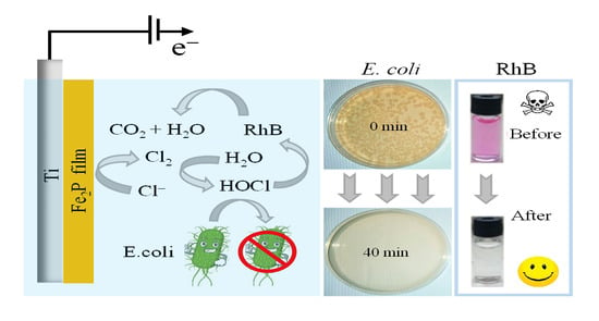
Iron Phosphide Precatalyst for Electrocatalytic Degradation of Rhodamine B Dye and Removal of Escherichia coli from Simulated Wastewater

1
Materials Research Laboratory, University of Nova Gorica, 5270 Ajdovscina, Slovenia
2
Laboratory for Environmental and Life Sciences, University of Nova Gorica, 5000 Nova Gorica, Slovenia
3
Wine Research Centre, University of Nova Gorica, Glavni Trg 8, 5271 Vipava, Slovenia
4
Institute of General and Inorganic Chemistry, Bulgarian Academy of Sciences, 1113 Sofia, Bulgaria
5
Department of Chemistry and Physics, Western Carolina University, Cullowhee, NC 28723, USA
6
The Jacob Blaustein Institutes for Desert Research, Ben-Gurion University of the Negev, Midreshet Ben-Gurion 84990, Israel
*
Author to whom correspondence should be addressed.
Catalysts 2022, 12(3), 269; https://doi.org/10.3390/catal12030269
Submission received: 19 January 2022 / Revised: 18 February 2022 / Accepted: 21 February 2022 / Published: 28 February 2022
(This article belongs to the Topic Electromaterials for Environment & Energy)

Abstract

:
Electrocatalysis using low-cost materials is a promising, economical strategy for remediation of water contaminated with organic chemicals and microorganisms. Here, we report the use of iron phosphide (Fe2P) precatalyst for electrocatalytic water oxidation; degradation of a representative aromatic hydrocarbon, the dye rhodamine B (RhB); and inactivation of Escherichia coli (E. coli) bacteria. It was found that during anodic oxidation, the Fe2P phase was converted to iron phosphate phase (Fe2P-iron phosphate). This is the first report that Fe2P precatalyst can efficiently catalyze electrooxidation of an organic molecule and inactivate microorganisms in aqueous media. Using a thin film of Fe2P precatalyst, we achieved 98% RhB degradation efficiency and 100% E. coli inactivation under an applied bias of 2.0 V vs. reversible hydrogen electrode in the presence of in situ generated reactive chlorine species. Recycling test revealed that Fe2P precatalyst exhibits excellent activity and reproducibility during degradation of RhB. High-performance liquid chromatography with UV-Vis detection further confirmed the electrocatalytic (EC) degradation of the dye. Finally, in tests using Lepidium sativum L., EC-treated RhB solutions showed significantly diminished phytotoxicity when compared to untreated RhB. These findings suggest that Fe2P-iron phosphate electrocatalyst could be an effective water remediation agent.

Graphical Abstract

1. Introduction

Electrochemical oxidation has emerged as a promising means of eliminating contaminants from water [1]. The growing presence in wastewaters of organic pollutants such as pharmaceuticals, pesticides and dyes has become a major concern, as has the presence of heavy metals and pathogenic microorganisms. Removal of these substances is complex and energy-inefficient [2,3,4,5,6,7]. Anodic oxidation of organics at electrode surfaces is one set of methods for removing these contaminants [8,9]. Direct oxidation occurs by electron transfer between the substrate molecule and the electrode surface [9,10], whereas indirect oxidation involves the generation of reactive oxygen species (ROS) or reactive chlorine species (RCS). ROS include hydroxyl radicals (•OH), hydrogen peroxide (H2O2) and ozone (O3). RCS include chlorine (Cl2), hypochlorous acid (HClO), chlorate (ClO) and chlorine radicals (Cl• or Cl2•−) [11,12,13]. RCS such as Cl2 and HClO have been shown to be effective in the degradation of alcohols [11], carboxylic acids [14], dyes [15], pharmaceuticals [16] and tannery effluents [17] and for inactivation of microorganisms [18]. During the process of RCS generation, oxidation of Cl ions yields Cl2, which is stable in acidic medium (pH < 3.3) or hydrolyzes to HClO (3.3 < pH < 7.5) and ClO ion (pH > 7.5) [11]. The standard potential for the Cl2 evolution (Cl/Cl2 1.36 V vs. normal hydrogen electrode (NHE)) is relatively low, making it an attractive option for efficient electrochemical wastewater treatment [19].
Electrochemical oxidation of organics usually allows the oxidation of pollutants to H2O and CO2. This approach is often used for remediation of organics, including dye molecules such as methylene blue [20], rhodamine B (RhB) [21] and methyl orange [20]. RhB removal from wastewater is particularly important due to its toxicity and carcinogenic effects [21].
The application of the electrocatalytic (EC) process for water disinfection has been investigated as well [22,23]. In water recycling, water disinfection constitutes the final crucial step, which represents the last barrier against harmful microorganisms [23,24]. Disinfection is necessary to remove harmful bacteria present in wastewater. These bacteria include Salmonella [25], Escherichia coli (E. coli) [26], Pseudomonas aeruginosa [18] and Enterococcus faecalis [27]. E. coli is the preferred indicator for fecal contamination in drinking water [28].
Materials such as platinum (Pt) [26,29], iridium oxide (IrO2) [30], titanium dioxide (TiO2) [31,32], tin dioxide (SnO2) [15,21,32], boron-doped diamond (BDD) [21,33] and dimensionally stable anodes (Ti/TiO2-RuO2, Ti/RuO2-IrO2) [15,34] have already been employed as electrocatalysts for RhB dye degradation and E. coli inactivation. Available evidence indicates that Pt and IrO2 are efficient catalysts for oxidation of Cl ions that exhibit low-onset potential (~1.42 V) for Cl2 evolution [35]. However, their widespread application is unfeasible since these materials are scarce and costly [36]. Other, less expensive materials, such as TiO2, SnO2 and BDD, are inefficient electrocatalysts since they require high overpotential for Cl2 evolution [19].
Transition metal phosphides (TMPs) such as iron phosphide, copper phosphide, cobalt phosphide and nickel phosphide [37,38] and transition metal phosphates (TMPHs) made of cobalt phosphate, nickel phosphate, manganese phosphate, iron phosphate, etc., have emerged as promising alternatives to the noble metal catalysts (e.g., Pt) for electrochemical water splitting [38,39]. TMPs and TMPHs show great promise as catalysts since they are made of abundant elements and offer high catalytic activity [38]. For example, Fe2P was demonstrated to deliver 10 mA cm−2 at an overpotential of 290 mV vs. RHE to drive O2 evolution reaction (OER) in 1 M KOH [40]. On the other side, TMPH made of nickel-iron hydroxylphosphate (NiFe-OH-PO4) was shown to deliver a current density of 20 mA cm−2 at an overpotential of 249 mV for OER [41]. In addition to OER studies, TMP made of ternary NiCoFe phosphide was demonstrated as a suitable catalyst for oxidation of Cl ions to Cl2 gas [42]. The latter ability of TMPs can be used as an effective strategy in wastewater treatment where Cl ions are present. Although TMPs are studied extensively, there are still unclear points associated with their stabilities observed during the water electrolysis experiments. The majority of the published articles on the use of TMPs in OER studies demonstrate the formation of a thin metal phosphate or metal oxide/hydroxide layer after the water electrolysis tests [38,43,44]. Often, the conclusion about the state of catalyst is drawn using techniques such as energy-dispersive X-ray spectroscopy or surface sensitive techniques such as X-ray photoelectron spectroscopy. However, to properly address possible phase conversions, the use of X-ray diffraction is also needed in addition to the above-mentioned techniques.
In the present study, Fe2P transformed into iron phosphate during electrocatalytic degradation of RhB dye and inactivation of E. coli bacteria. Since the phase is not well defined, it is abbreviated as Fe2P-iron phosphate. To our knowledge, Fe2P-iron phosphate electrocatalysts have never been applied for the degradation of organics and disinfection of water. First, we synthesized colloidal Fe2P nanoparticles (NPs) using a solvothermal approach, followed by spin-coating titanium (Ti) substrates with Fe2P. To activate the Fe2P catalyst, a short heat treatment at 450 °C was carried out. The role of heat treatment is two-fold: first, to activate the catalyst by removal of organic capping molecules; second, to improve the adhesion of the catalyst onto the substrate [45]. The degradation of RhB was monitored using UV-Vis spectroscopy and high-performance liquid chromatography (HPLC) with spectroscopic monitoring. The inactivation of E. coli was monitored by plating bacteria suspension onto a medium after the treatment. Bacterial regrowth experiments and enumeration confirmed the rapid and complete inactivation of E. coli. Recycling test and linear sweep voltammetry revealed that Fe2P-iron phosphate electrode exhibits excellent reproducibility. The catalysts were characterized using scanning electron microscopy (SEM), transmission electron microscopy (TEM), X-ray photoemission spectroscopy (XPS) and X-ray diffraction (XRD), along with other suitable electrochemical techniques.

2. Results and Discussion

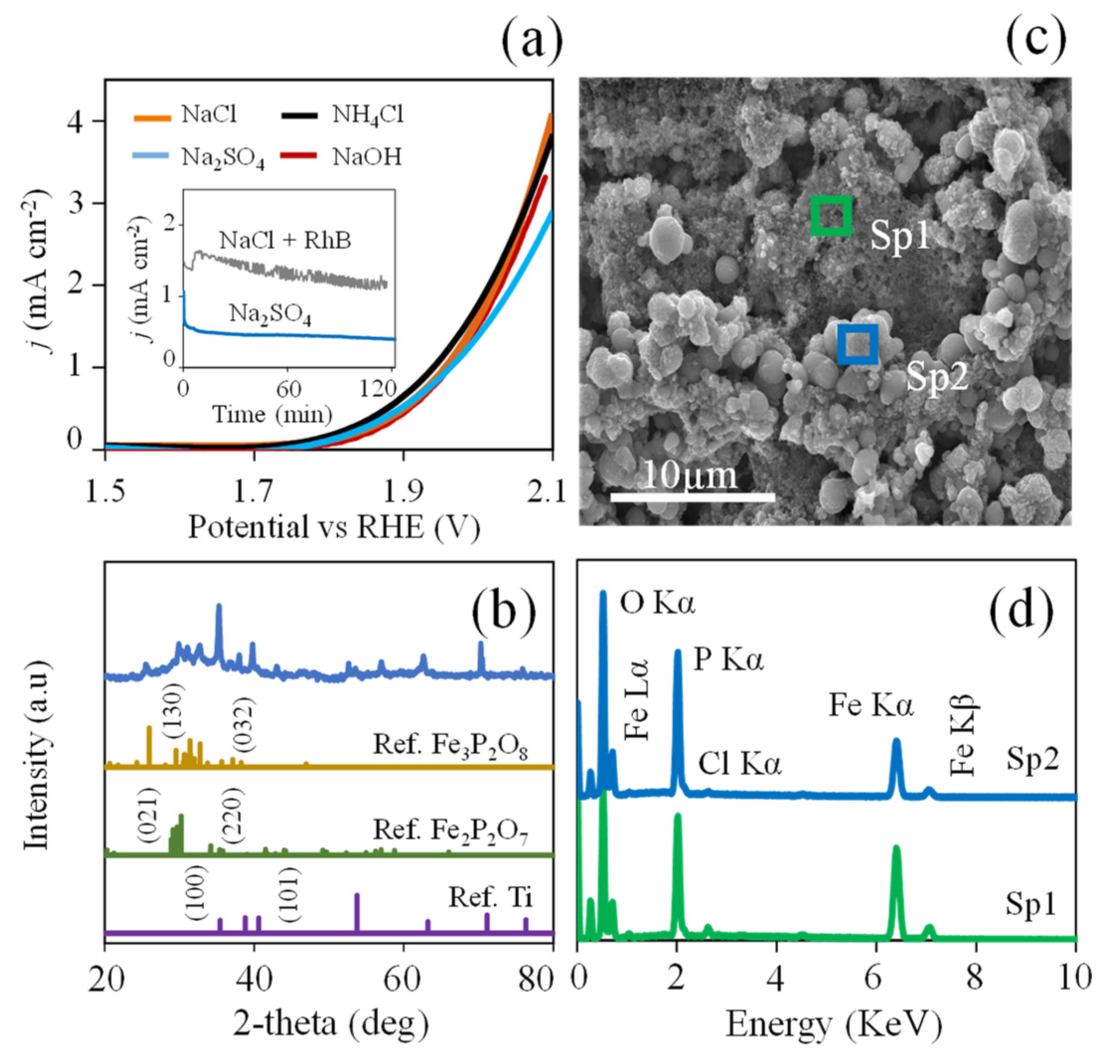
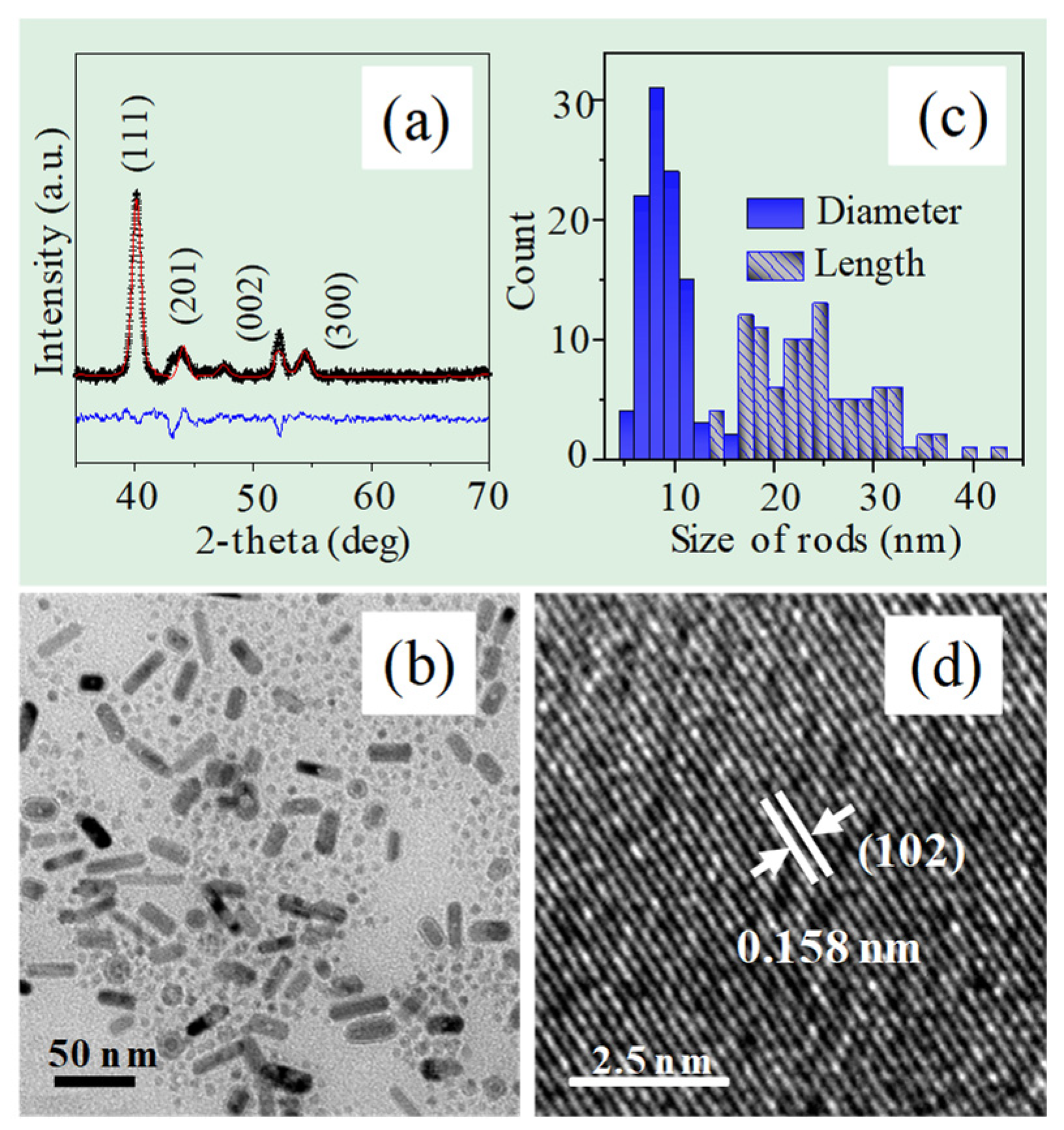
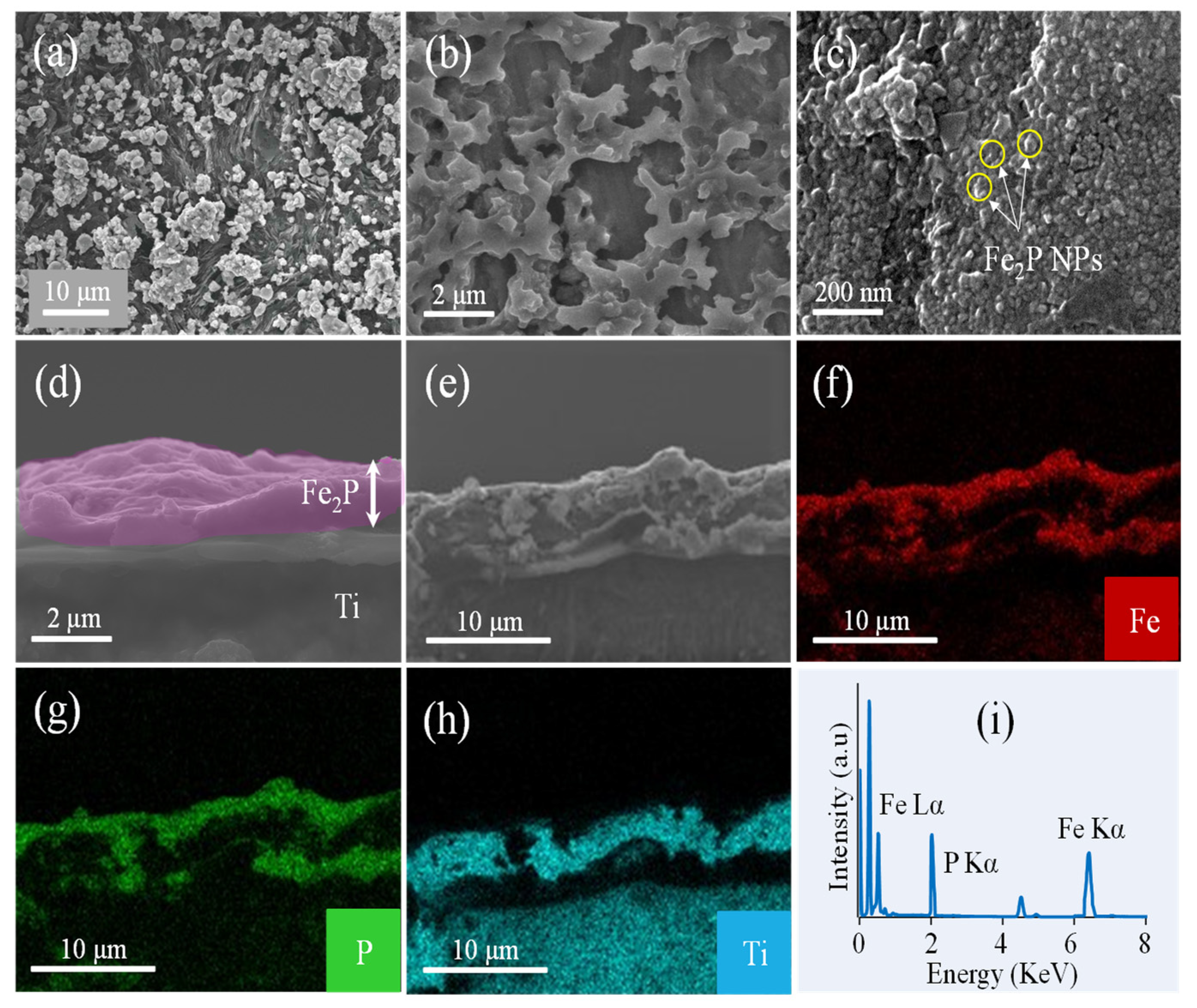
2.1. Characterization of Fe2P Thin Films

XRD diffractogram of the sample taken before heat treatment revealed that Fe2P is its sole constituent (Figure 1a). The intense diffraction peaks at 40.37, 44.30 and 52.91° correspond to (111), (201) and (002) crystallographic planes of the hexagonal Fe2P (P 6 ¯ 2m, PDF # 1008826). The calculated crystal lattice parameters are in good agreement with the literature data for hexagonal Fe2P (a = b = 5.851 ± 0.0034 Å, and c = 3.507 ± 0.0026 Å) [46]. The crystallite size and the intrinsic strain calculated using the Williamson−Hall (W−H) method yielded an average size of 18 ± 0.0010 nm and 4.5 × 10⁻³ ± 0.0007 a.u., respectively (Text S1, Figure S1). The reliability of the refined fit was assessed by the weighted profile (Rwp) and Bragg (Rb) factor values that, at Rwp = 4.23% and Rb = 4.11%, met the established criteria (Rwp < 20%) for good refinement [47]. The XRD pattern of the Fe2P catalyst (Figure S2) after the heating procedure (450 °C) was almost identical to that recorded for the initially synthesized Fe2P NPs. This result confirms that the stoichiometry and crystal structure were unchanged by the procedure.
TEM studies revealed that the obtained Fe2P sample contained two morphologies: nanospheres (NSs) and nanorods (NRs) (Figure 1b). The nanosphere Fe2P had a uniform diameter (about 5 ± 0.1 nm on average, as shown in Figure S3), while Fe2P NRs varied in size (reaching 8.79 ± 0.03 nm in diameter and 23 ± 0.98 nm in length on average, as shown in Figure 1c). HR-TEM studies indicated that the lattice spacing of 0.158 nm corresponds to the (102) crystal plane of hexagonal Fe2P (Figure 1d).
We studied the morphology of the obtained Fe2P thin film using SEM. As seen in Figure 2a,b, the morphology of Fe2P thin film contains large aggregates and densely packed NPs. An SEM image taken at high magnification shows that the diameter of Fe2P particles is on the order of 200 nm (Figure 2c). The thickness of the resulting Fe2P film, as determined from the cross-section SEM image, is about ~2 µm (Figure 2d). EDS analysis combined with elemental maps for Fe and P confirmed that these agglomerates were made of iron phosphide and that the stoichiometric ratio of Fe:P elements is 2:1 (Figure 2e−i).

2.2. Electrochemical Studies

The catalytic activity of Fe2P films was studied using linear sweep voltammetry (LSV). Figure 3a shows liner sweep voltammograms of Fe2P film recorded in four electrolytes (0.06 M), namely NaCl, NH4Cl, Na2SO4 and NaOH. In each case, the recorded onset potential for Faradaic processes is close to ~1.7 V vs. RHE. The current in Na2SO4 and NaOH electrolytes is lower due to the dominating O2 evolution reaction [48]. However, in the presence of NaCl and NH4Cl electrolytes, O2 evolution at the anode competes with oxidation of Cl ions leading to Cl2. We also performed an LSV study with the Fe2P catalyst in 10−5 M RhB solution (0.06 M NaCl) before the heat treatment experiment (Figure S4). We found that the current density is insufficiently low (0.05 mA cm−2 at 2 V vs. RHE) compared to that after the heating procedure at 450 °C. The goal behind this heat treatment was to remove the organics that act as an insulating layer between the iron phosphide catalyst and the electrolyte [45]. The slopes of Tafel plots (plots of potential versus logarithm of current) are useful for interpreting polarization curves [45]. We found that the Tafel slopes obtained for Fe2P depended on the electrolyte. In solutions containing 0.06 M electrolyte, the Tafel slopes were 144 (NaCl), 218 (NH4Cl), 227 (NaOH) and 245 (Na2SO4) mV dec−1 (Figure S5a). Since lower Tafel slope correlates with higher catalyst activity, this result is consistent with oxidation occurring fastest in NaCl solution (Text S2). Interfacial charge-transfer kinetics on Fe2P were analyzed using EIS measurements. This analysis showed that the charge transfer resistance (Rct) was low at high bias voltages, indicating fast charge-transfer kinetics during water oxidation reaction (Rct < 40 ohm cm2) [49]. A Nyquist plot and a discussion of the relevant circuit and its analysis are presented in the supplemental section (Figure S5c). The electrochemically active surface area (ECSA) of the initial Fe2P film was determined from the CVs obtained in 1 M KOH (pH 14) (Figure S6) [50]. The calculated ECSA value of 0.6 cm2 exceeded the 0.3 cm2 geometric area (assuming a flat surface). The details of the calculation are described in Text S3.
Chronoamperometric (I-t) experiments demonstrated that the Fe2P precatalyst satisfactorily retained the initial current level during the 2 h test time. These tests were conducted in 0.06 M Na2SO4 and in 0.06 M NaCl with 10−5 M RhB at an applied bias of 2.0 V vs. RHE (inset in Figure 3a). In 10−5 M RhB solution, we observed a slight decrease in current level from 1.5 to 1.3 mA cm−2 during the initial 40 min. However, the current level stabilized later. After the electrolysis, the film was studied using XRD (Figure 3b). Although there is an insignificant change in the current level during electrolysis, the XRD shows clearly the transformation of Fe2P phase into iron phosphate phase (mixture of Fe2P2O7 (PDF # 2300034) and Fe3P2O8 (PDF # 2300033)). The obtained iron phosphate phase is composed of two phosphate phases, but we believe that a uniform single phase may occur after a sufficiently long electrolysis time. In addition to the XRD study, we also performed point EDS measurements from the image given in Figure 3c after the EC degradation of RhB in 0.06 M NaCl (Figure 3d). EDS analysis confirmed that the atomic ratio of Fe:P is equal to 1.8:1 (Sp1). However, when we recorded spectrum 2 (Sp2), we noticed that the atomic ratio of Fe:P is equal to 1.4:1. In both spectra, we observed some additional peaks such as oxygen and Cl ions. Images with elemental maps for Fe, P, Cl, O and C taken from the Fe2P sample (after electrolysis) are provided in Figure S7. The low-intensity peak of Cl ions indicates that these are adsorbed on the Fe2P surface in minor quantities (0.6 at.% ≥). The intense peak of oxygen confirms the formation of iron phosphate phase. From the obtained data, we concluded that a large amount of Fe2P film was converted to iron phosphate. The amount of metal phosphate obtained exceeds that reported in other systems where it was claimed that phase conversion occurs only on a few atomic surface layers [38,51].

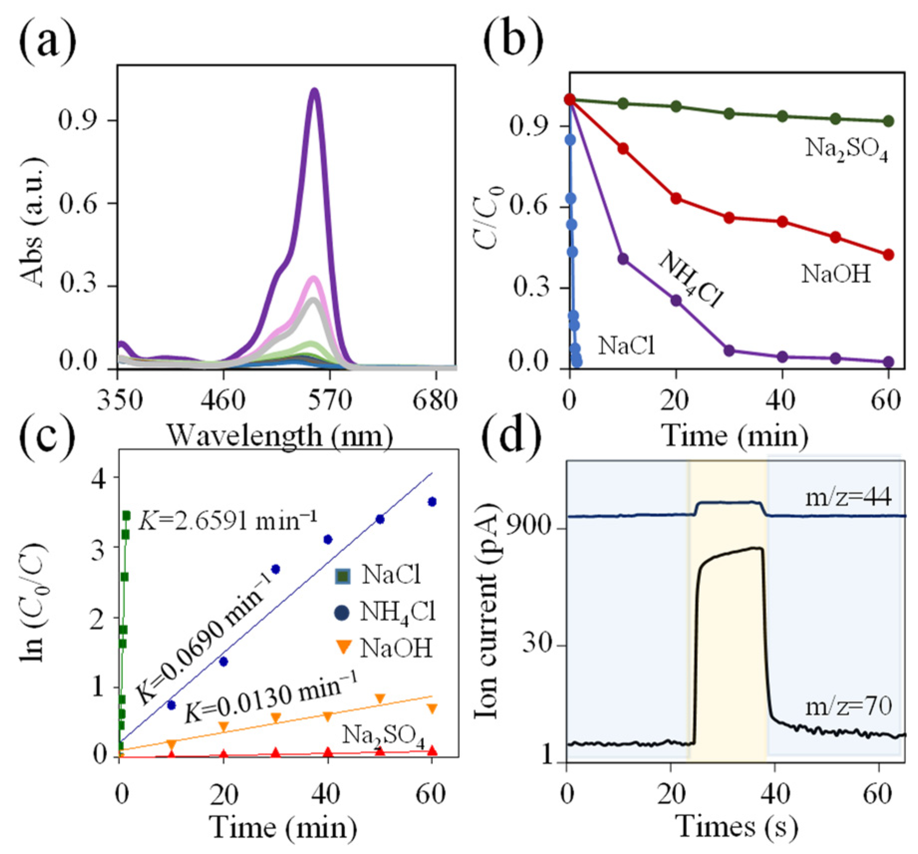
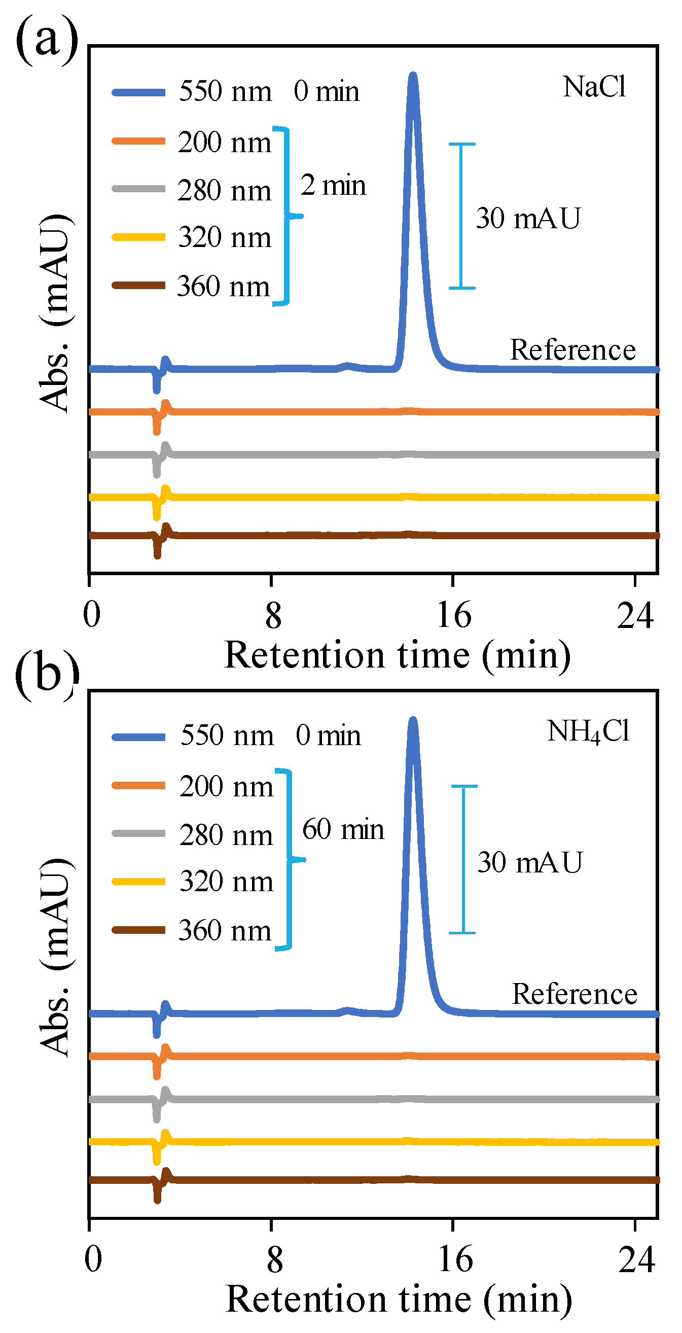
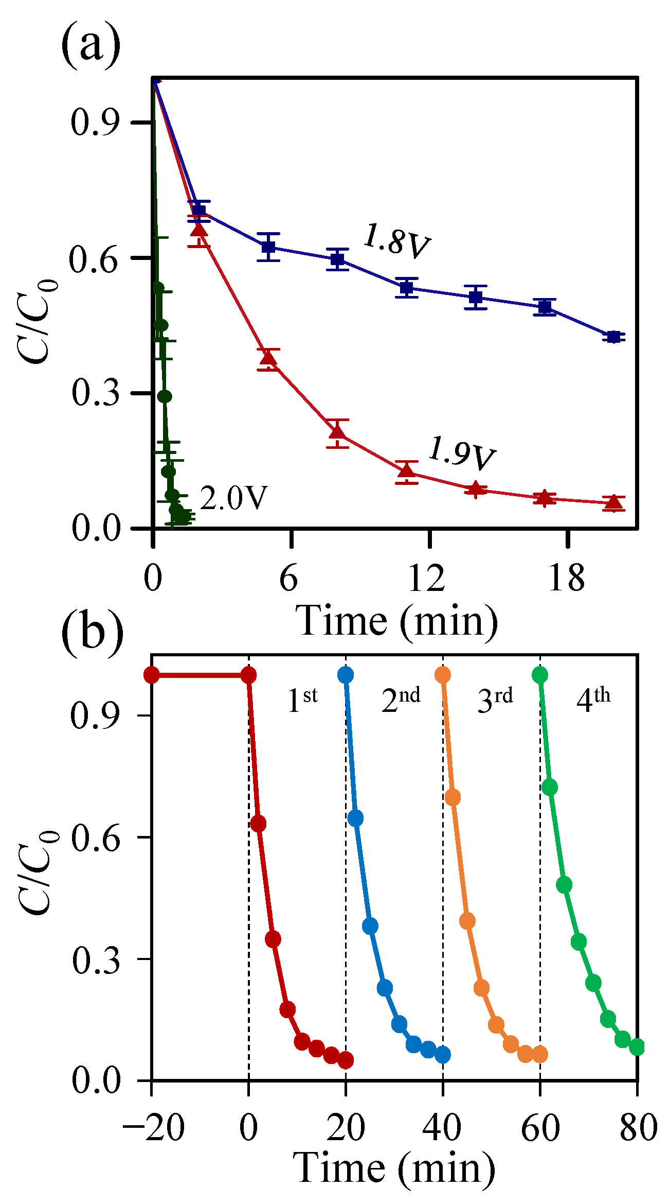
2.3. RhB Dye Degradation Studies

The activity of the Fe2P-iron phosphate thin film as an anode material for organic molecule degradation was studied by monitoring its effect on the absorbance spectra of a solution of RhB dye. As shown in Figure 4a, the 550 nm absorption peak of RhB was completely degraded to baseline in 40 min in 0.06 M NH4Cl (pH 5). The degradation is much faster in 0.06 M NaCl, being complete in under 2 min (a magnified region of RhB degradation in 0.06 M NaCl is shown in Figure S8). The slower degradation rate in NH4Cl electrolyte is attributed to ammonium cation (NH4+) oxidation which competes with Cl oxidation [52]. Pérez et al. (2012) showed that NH4+ degrades to N2 and nitrate (NO3) in reactions with oxidizing chlorine species [52] (Equations (1) and (2)):
2/3 NH4+ + HClO 1/3 N2 + H2O + 5/3 H+ + Cl
NH4+ + 4 HClO NO3 + H2O + 6H+ + 4 Cl
When Na2SO4 and NaOH (pH 5) were used as electrolytes, RhB dye degradation was negligible (Figure 4b). What degradation does occur is ascribed to the formation of SO4•− and •OH species. However, it is well known that in an acidic environment SO4•− radicals are less effective than •OH radicals which favorably form in alkaline solutions [53]. In acidic media at pH 5, the generation of •OH is assumed to occur unfavorably. AlHamedi et al. (2009) demonstrated that •OH reacts with SO42− ions, as shown in the following reaction:
SO42− + •OH SO4•− + OH
As a control experiment, we assessed the catalytic activity of pure Ti substrate in 0.06 M NaCl. In the absence of Fe2P-iron phosphate, the bare Ti produced indistinct RhB dye degradation (Figure S8). We also investigated the kinetics of Fe2P-iron phosphate catalyzed RhB oxidation. The RhB dye decomposition rate, presented in the form of degradation efficiency (D), was calculated using the following equation: D (%) = ((C0Ct)/C0) × 100, where C0 is the initial concentration (t = 0 min) and Ct is the concentration at a defined reaction time point [54]. The highest D value (equivalent to 98%) was achieved in 0.06 M NaCl within 1.3 min (Figure S9). The change in RhB dye concentration was assessed by a pseudo-first-order kinetic model: ln(C0/C) = k1t, where C and C0 are the RhB dye concentrations at time t and time zero, respectively, and k1 is the pseudo-first-order rate constant calculated from the slope of the straight line (Text S4, Table S1) [55]. Our results are in good agreement with other published studies of electrochemical RhB degradation [15]. As shown in Figure 4c, the highest k1 = 2.6591 min−1 was obtained with NaCl electrolyte. This larger k value indicates that RhB dye degraded about 1772 times faster than in Na2SO4 (k1 = 0.0015 min−1) and 204 times faster than in NaOH electrolyte (k1 = 0.0130 min−1). Here, the obtained k1 constants in Cl-containing electrolytes using Fe2P-iron phosphate are higher than on other anode materials reported in earlier electrochemical studies. For example, using Ti/RuO2–IrO2 catalyst during RhB dye degradation under EC condition yielded k1 = 0.079 min−1 [15].
Coumarin was used as a probe molecule to determine whether •OH radicals participate in RhB degradation in chloride solutions (Text S5). This molecule reacts with •OH radicals to form a highly fluorescent product called 7-HC which has a peak at ~456 nm [56]. The absence of a 7-HC emission peak suggests that •OH radicals are suppressed in NaCl electrolyte (Figure S10) [11]. Results of the experiments described above suggest that EC degradation of RhB occurs via an indirect oxidation mechanism in which RCS, but not ROS, play a crucial role [57]. To further test this hypothesis, we measured the evolution of in situ generated Cl2 using the DPD colorimetric method [58]. In the presence of Cl2, DPD is oxidized to a radical cation (DPD•+) with an absorption peak at 515 nm [59]. In these experiments, we observed the growth of the 515 nm peak, further supporting the proposal that RCS participate in RhB degradation (Figure S11). The results are consistent with the EC-chlorine system where HClO plays an essential role during the degradation of RhB [30,60]. In a similar way, Baddouh et al. (2018) have previously demonstrated the electrooxidation of Cl to HClO at Ti/RuO2–IrO2 anode. At pH 5, HClO is expected to be the dominant form of RCS [58].
To further confirm RCS participation in the electrochemical degradation of RhB, we monitored the evolution of Cl2 using mass spectrometry (MS) (Figure 4d). The sudden rise in ionic current at 25 s indicates the presence of fragment ions with the mass-to-charge ratio (m/z) for Cl2 and CO2 equal to 70 and 44, respectively. Here, CO2 is produced from RhB degradation during the electrocatalytic oxidation process. On the counter electrode, the H2 gas is evolved (Figure S12).
Further support for our hypothesis that HClO participates in RhB degradation comes from chemical oxidation studies with NaOCl (Figure 5). We found that complete dye decolorization was achieved using ~0.4 mM NaOCl. This result further supports the hypothesis that RhB decolorization in EC mode is mainly conducted by the generated HClO species (the RhB degradation mechanism is discussed in detail in Text S6). Under potentiostatic conditions (at 2.0 V vs. RHE) during the 4 min reaction process in 0.06 M NaCl, the amount of measured HClO is estimated as 2.5 mg L−1 (Figure S11), which corresponds to a current to HClO conversion efficiency of 73.7% (Text S7).
As indicated in studies of EC-mediated azo dye degradation, applied potential can significantly influence the degradation efficiency [5]. Herein, we studied RhB degradation in 0.06 M NaCl at three bias potentials (1.8, 1.9 and 2.0 V vs. RHE, Figure 6a). In this experiment, > 97% degradation was observed in 1.3 min at 2.0 V and in 20 min at 1.9 V (voltage vs. RHE). In contrast, at an applied potential of 1.8 V, 56% efficiency was achieved in 20 min (Figure S9b). Thus, higher potentials give rise to fast oxidation of Cl to RCS, leading to rapid dye degradation.
We evaluated the stability of the Fe2P-iron phosphate film against corrosion under conditions of the EC reaction by performing an experiment where a single Fe2P-iron phosphate film was used to degrade multiple samples of RhB. Figure 6b shows the result of this recycling test for RhB degradation at 1.9 V vs. RHE bias potential in 0.06 M NaCl. The data in Figure 6b reveal over 97% RhB degradation efficiency for each of the four runs, confirming the stability of Fe2P-iron phosphate thin film against corrosion and the potential for its reuse in EC studies.
The stability of the Fe2P-iron phosphate films was further validated by LSV characterization of films before and after the reusability tests. We characterized the electrochemical activity of the film by LSV and the surface morphology by SEM (Figure S13). The LSV measurements revealed a slight increase in current after the stability test. The SEM measurements showed that film morphology was unaltered by the EC process. Both these results confirm the adequacy and compatibility of this electrode in EC wastewater treatment.
The composition and chemical state of Fe2P thin film were characterized by XPS. As with the characterization studies described above, we measured XPS data before and after exposing the Fe2P film to EC conditions. The spectrum of the Fe2P electrode before RhB degradation is shown in Figure 7a. Selected regions of the XPS spectra recorded before and after RhB degradation are shown in Figure 7b–d. The photoelectron Fe 2p peaks exhibit a doublet at 711.0 eV (Fe 2p3/2) and 724.0 eV (Fe 2p1/2) due to spin–orbit splitting. A less intense peak is also observed at 713.5 eV. These peaks can be attributed to the formation of iron(III) phosphate on the Fe2P surface [61]. The P 2p spectrum displays two peaks with 133.0 and 134.0 eV binding energies, which are attributed to P 2p3/2 and P 2p1/2 levels of P in the Fe2P [61]. The peak at 133 eV can be assigned to P-C binding [62]. Because the surface oxidation of the Fe2P particles is unavoidable, the peak at 134.0 eV has been observed for phosphorus in a high oxidation state and refers to surface-oxidized P species [61]. These findings suggest that these species can also be assigned to the formation of a thin iron phosphate layer. To gain a better understanding of Fe2P catalyst stability, we also recorded XPS spectra after the EC degradation of RhB dye (Figure 7). The intensities of the XPS core-level spectra of Fe 2p and P 2p greatly decreased after the test. Moreover, an intense peak formed at 201.5 eV and was attributed to the Cl 2p core-level emission (Figure 7d). These results confirm that, during EC degradation, Cl ions are strongly adsorbed on the Fe2P surface. Moreover, the large amount of chloride ions adsorbed on the surface attenuates the signal from Fe2P, thus markedly decreasing the intensity of the Fe 2p and P 2p peaks. These results are in good agreement with the EDS analysis.
We employed HPLC to monitor RhB dye degradation. The reference sample of RhB dye produced an apparent peak at 15.0 min elution time (Figure 8). We monitored the disappearance of the RhB absorbance peak (λ = 550 nm) in NaCl, NH4Cl and Na2SO4. As shown in Figure S14, complete degradation was accomplished within 2 min in 0.06 M NaCl and 60 min in 0.06 M NH4Cl while degradation in 0.06 M Na2SO4 remained incomplete after 180 min. Monitoring degradation at multiple detection wavelengths failed to show the appearance of additional peaks in the HPLC chromatograms. This indicates that no degradation by-products with strong absorption in the UV-Vis are formed. From this, we conclude that complete degradation occurs in Cl-containing electrolytes (Figure 8). The use of HPLC was also motivated by the fact it overcomes the interference of Cl ions seen as a bottleneck in other methods such as the total organic carbon and the chemical oxygen demand.
In earlier studies related to EC wastewater treatment, chlorate or perchlorate ions were identified as by-products [63]. We note that these by-products were observed when the applied current densities were in the 5–30 mA cm−2 range [64]. Consequently, we believe that chlorate formation is less likely under the conditions adopted in our study since the current densities do not exceed 2 mA cm−2. Further, the detection at shorter wavelengths (200 nm) in HPLC demonstrates that intermediates with lower molecular weight (phthalic acid, benzoic acid, α-hydroxyglutaric acid, etc.) which might form during RhB degradation [65] are absent from our reaction medium after the EC treatment process.

2.4. Phytotoxicity Test of RhB and Electrochemical Inactivation of E. coli Bacteria

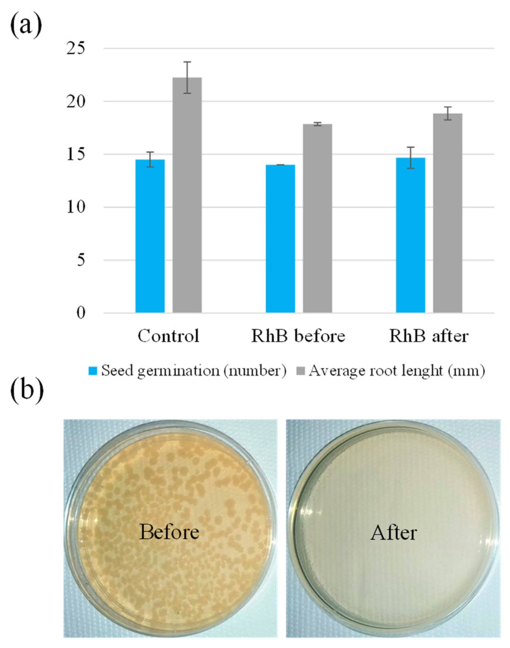
2.4.1. Phytotoxicity Test of RhB

To assess the quality of EC-treated RhB water solutions, phytotoxicity test was performed using L. sativum whereby seed germination index and root growth of L. sativum were used to evaluate the phytotoxic effect of RhB in 0.06 M NaCl at pH 5 (Figure S15). Before electrochemical treatment, the germination index for L. sativum in RhB solution, 0.06 M NaCl, pH 5 was 75.9%. After electrochemical treatment of this solution, the germination index rose to 84%. Similarly, the average root length increased from 17.7 to 18.9 mm after treatment (Figure 9a). These results show electrochemically treated solutions have little to no phytotoxicity [66] (further details about our phytotoxicity study are provided in Text S8).

2.4.2. Electrochemical Inactivation of E. coli Bacteria

Inactivation of E. coli using the Fe2P-iron phosphate thin film electrode was investigated in NaCl electrolyte. The catalytic activity of Fe2P-iron phosphate films was determined using the LSV method. Figure S16a shows LSV characteristics of Fe2P-iron phosphate film recorded in 0.06 M NaCl (pH 5), with the initial E. coli concentration, determined with plating, being 1.1 × 10⁸ CFU/mL. The recorded onset potential is close to 1.7 V vs. RHE. Figure S16b shows the chronoamperometric experiment of Fe2P-iron phosphate catalyst conducted in 0.06 M NaCl with 1.1 × 10⁸ CFU/mL of E. coli at an applied bias of 2.0 V vs. RHE. We observed a decrease in current density during the first 90 min, starting from 0.9 mA cm−2. However, the current density later stabilized and reached a plateau at 0.46 mA cm−2. The activity of the Fe2P-iron phosphate electrode was further validated by LSV after the stability test (inset in Figure S16a). The LSV measurement revealed a slight decrease in current after the 120 min stability test, which confirms the suitability of this electrode in EC water disinfection. After 40 min of EC exposure at 0.9 mA cm−2, no viable bacteria were detected, indicating 100% disinfecting efficiency in NaCl electrolyte (Figure 9b). However, in comparison to the initial E. coli concentration, we observed a 26.7% decline in the control bacterial solution after 160 min incubation in 0.06 M NaCl (pH 5) without EC treatment.
One of the major concerns of electrodisinfection involving active chlorine is the formation of chlorination by-products (ClO2 and ClO3). However, it is known that chlorate formation occurs at higher current densities and is less likely to evolve under the conditions (0.9 mA cm−2) adopted in our study [64].
All these results indicate that the EC treatment with Fe2P-iron phosphate electrodes is a promising alternative procedure compared with other known materials considering the high-efficiency processes for dye degradation (Table S2) and water disinfection (Table S3).

3. Materials and Methods

3.1. Chemicals

The following chemicals were used in this study: oleylamine (70%, OLA), iron pentacarbonyl (99.9%, Fe(CO)5), acetone (95%), ethanol (98%) and potassium hydroxide (97%, KOH), obtained from Sigma-Aldrich; triphenylphosphine (99%, TPP), RhB (≥95%), squalene (98%, SQ), chloroform (99.5%, CHCl3), sodium sulfate (99%, Na2SO4), sodium chloride (99%, NaCl), coumarin and sodium hypochlorite (NaOCl), purchased from Alfa Aesar; ammonium chloride (≥99%, NH4Cl) and 7-hydroxycoumarin (7-HC), acquired from Acros Organics; and a titanium block (99.9%) obtained from Baoji Quanjin Industry & Trade Co., Ltd. (Baoji, China).

3.2. Preparation of Fe2P Thin Films

Fe2P was synthesized using TPP precursor adopting the method described by Chouki et al. (2020) [45]. The synthesis procedure and the experimental measurements are described in detail in Text S9 and S10 in Supporting Information (SI).

3.3. E. coli Preparation and Evaluation of Removal Efficiency

One colony from a 2-day-old culture of E. coli DSM 489, grown on tryptic soy agar (Fluka), was inoculated into 50 mL liquid tryptone medium (Fluka) in 250 mL Erlenmeyer flask and incubated for 16 h at 37 °C (150 rpm). The culture was centrifuged at 4000 rpm for 10 min, and bacterial cells were washed with filter-sterilized 0.06 M NaCl (pH 5) solution. Bacterial solution was adjusted to O.D. (600 nm) 0.15 and used for electrochemical removal of 1.1 × 10⁸ CFU/mL E. coli bacteria in 0.06 M NaCl at an applied bias of 2.0 V vs. RHE.
To evaluate E. coli removal efficiency, samples were withdrawn at four different time points with 40 min increment during the EC experiment. The control bacterial suspension without any treatment was also plated at the beginning and at the end of the experiment. Serial dilutions (10-fold) of samples were spread onto plates with the tryptic soy agar (Fluka). Plates were counted after 24 h incubation at 37 °C and bacterial counts were expressed as CFU/mL.

3.4. Phytotoxicity Test Using Lepidium sativum L.

Lepidium sativum L. (L. sativum) was used to assess the acute toxicity of RhB before and after treatment in 0.06 M NaCl at pH 5. The test is described in the SI.

4. Conclusions

In this work, we report for the first time the transformation of Fe2P into iron phosphate during EC degradation of RhB dye (98%) and inactivation of E. coli bacteria (100%). We demonstrated that, under the experimental conditions, Cl ions are oxidized to HClO, which plays an essential role in the water treatment process. The recycling test (degradation test) of RhB dye over Fe2P-iron phosphate film at 1.9 V vs. RHE revealed excellent reproducibility. Phytotoxicity tests revealed that EC treatment of RhB solutions decreased the inhibition of L. sativum germination, which serves as an indicator for reduced toxicity. Hence, this work demonstrates the tremendous potential of Fe2P-iron phosphate as an efficient electrocatalyst in water cleaning studies. We propose that EC degradation of organics and inactivation of pathogenic bacteria could be also extended to other TMPHs.

Supplementary Materials

The following supporting information can be downloaded at: https://www.mdpi.com/article/10.3390/catal12030269/s1. Text S1: Rietveld refinement analysis and Williamson–Hall method. Figure S1: Williamson–Hall plot. Figure S2: XRD pattern of Fe2P after heat treatment. Figure S3: Size distribution of Fe2P NSs. Figure S4: LSV characteristic of Fe2P particles recorded in 10−5 M RhB + 0.06 M NaCl conducted before heat treatment. Text S2: Tafel plots and EIS. Figure S5: (a) Tafel plots of different electrolytes; (b) Nyquist plot of Fe2P thin film in 0.06 M Na2SO4; (c) Charge transfer resistance vs. applied voltages; (d) A circuit element used to fit the data. Text S3: Calculation of electrocatalytic active surface area. Figure S6: CVs of Fe2P at different scan rates in 1 M KOH; (b) Current vs. scan rate taken from (a). Figure S7: Images with elemental maps are given for Fe, P, Cl, O and C taken from the Fe2P sample (after electrolysis). Figure S8: Time profiles of RhB degradation in NaCl conducted with Ti and Fe2P-iron phosphate electrodes. Figure S9: Degradation efficiency of RhB. Text S4: Kinetic models. Table S1: Pseudo-first-order and pseudo-second-order rate constants and correlation coefficients of RhB dye on Fe2P-iron phosphate film. Text S5: Fluorescence spectra of Fe2P-iron phosphate catalyst in 20 µM coumarin. Figure S10: Fluorescence spectra of Fe2P catalyst in 20 µM coumarin before and after the test. Figure S11: Detection of HClO by DPD method. Figure S12: MS measurement of H2 and O2 gas during the RhB degradation. Text S6: Degradation mechanism of RhB dye. Text S7: Calculation of the current generation efficiency of HClO. Figure S13: LSV plots and SEM images of Fe2P-iron phosphate electrode recorded before and after the recycling test. Figure S14: HPLC of 1×10⁻⁵ M RhB solution in the presence of NaCl, NH4Cl and Na2SO4. Text S8: Phytotoxicity test using Lepidium sativum L. Figure S15: Images of Lepidium sativum L. incubated in Petri dishes with RhB before and after EC treatment. Figure S16: LSV of Fe2P-iron phosphate catalyst in NaCl seeded with 1.1 × 10⁸ CFU/mL of E. coli bacteria and I-t plot obtained in 0.06 M NaCl + 1.1 × 10⁸ CFU/mL of E. coli at 2.0 V vs. RHE. Table S2: Selected materials used in EC degradation of different dye molecules. Table S3: Selected materials used in EC inactivation of E.coli bacteria. Text S9: Synthesis and characterization of Fe2P thin film. Text S10: Catalyst evaluation. Figure S17: Photograph of the cappuccino cell and EC cell used in the dye degradation studies. Table S4: Characteristics of RhB dye. [67,68,69,70,71,72,73,74,75,76,77,78,79,80,81,82,83,84,85,86,87,88,89,90,91,92] are cited in the Supplementary Materials.

Author Contributions

T.C. designed and conducted the experiments, analyzed the data and wrote the manuscript. M.M. contributed to DPD measurements. J.T. carried out the HPLC measurements. L.B. contributed to phytotoxicity tests, inactivation of E. coli bacteria and fundraising. P.S. carried out the XPS measurements. E.J. contributed to phytotoxicity tests. J.S.S. contributed to manuscript editing. M.V. contributed to manuscript editing. A.F. contributed to manuscript editing. S.E. supervised the work and contributed to data analysis, manuscript writing, editing, fundraising and project administration. All authors have read and agreed to the published version of the manuscript.

Funding

This research was funded by the Slovenian Research Agency under the bilateral project for scientific cooperation between Slovenia and the State of Israel (NI-0002). Scholarships were provided by the Public Scholarship, Development, Disability and Maintenance Fund of Slovenia for PhD studies at the University of Nova Gorica. Financial support was provided by the Slovenian Research Agency (research core funding: P2-0412).

Data Availability Statement

Data are contained within the article or Supplementary Materials.

Acknowledgments

This work was financially supported by the Slovenian Research Agency under the bilateral project for scientific cooperation between Slovenia and the State of Israel (NI-0002). T. Chouki and M. Machreki acknowledge the scholarships provided by the Public Scholarship, Development, Disability and Maintenance Fund of Slovenia (Ad futura program) for PhD studies at the University of Nova Gorica. S. Emin and M. Valant acknowledge the financial support from the Slovenian Research Agency (research core funding: P2-0412).

Conflicts of Interest

The authors declare that they have no known competing financial interests or personal relationships that could have influenced the work reported in this paper.

References

  1. Oturan, M.A. Electrochemical advanced oxidation technologies for removal of organic pollutants from water. Environ. Sci. Pollut. Res. 2014, 21, 8333–8335. [Google Scholar] [CrossRef] [PubMed] [Green Version]
  2. Faouzi Elahmadi, M.; Bensalah, N.; Gadri, A. Treatment of aqueous wastes contaminated with Congo Red dye by electrochemical oxidation and ozonation processes. J. Hazard. Mater. 2009, 168, 1163–1169. [Google Scholar] [CrossRef] [PubMed]
  3. Anas, M.; Han, D.S.; Mahmoud, K.; Park, H.; Abdel-Wahab, A. Photocatalytic degradation of organic dye using titanium dioxide modified with metal and non-metal deposition. Mater. Sci. Semicond. Process. 2015, 41, 209–218. [Google Scholar] [CrossRef]
  4. Raza, N.; Raza, W.; Gul, H.; Kim, K.H. ZnO–ZnTe hierarchical superstructures as solar-light-activated photocatalysts for azo dye removal. Environ. Res. 2021, 194, 110499. [Google Scholar] [CrossRef] [PubMed]
  5. Fan, L.; Zhou, Y.; Yang, W.; Chen, G.; Yang, F. Electrochemical degradation of aqueous solution of Amaranth azo dye on ACF under potentiostatic model. Dye. Pigment. 2008, 76, 440–446. [Google Scholar] [CrossRef]
  6. Zhao, S.; Li, S.; Zhao, Z.; Su, Y.; Long, Y.; Zheng, Z.; Cui, D.; Liu, Y.; Wang, C.; Zhang, X.; et al. Microwave-assisted hydrothermal assembly of 2D copper-porphyrin metal-organic frameworks for the removal of dyes and antibiotics from water. Environ. Sci. Pollut. Res. 2020, 27, 39186–39197. [Google Scholar] [CrossRef]
  7. Hashim, K.S.; Kot, P.; Zubaidi, S.L.; Alwash, R.; Al Khaddar, R.; Shaw, A.; Al-Jumeily, D.; Aljefery, M.H. Energy efficient electrocoagulation using baffle-plates electrodes for efficient Escherichia coli removal from wastewater. J. Water Process Eng. 2020, 33, 101079. [Google Scholar] [CrossRef]
  8. Bensalah, N.; Louhichi, B.; Abdel-Wahab, A. Electrochemical oxidation of succinic acid in aqueous solutions using boron doped diamond anodes. Int. J. Environ. Sci. Technol. 2012, 9, 135–143. [Google Scholar] [CrossRef] [Green Version]
  9. Ammar, H.B.; Brahim, M.B.; Abdelhédi, R.; Samet, Y. Green electrochemical process for metronidazole degradation at BDD anode in aqueous solutions via direct and indirect oxidation. Sep. Purif. Technol. 2016, 157, 9–16. [Google Scholar] [CrossRef]
  10. Patil, S.A.; Hägerhäll, C.; Gorton, L. Electron transfer mechanisms between microorganisms and electrodes in bioelectrochemical systems. Bioanal. Rev. 2014, 1, 71–129. [Google Scholar] [CrossRef]
  11. Koo, M.S.; Chen, X.; Cho, K.; An, T.; Choi, W.; Chen, X.; Cho, K.; An, T.; Choi, W. In situ photoelectrochemical chloride activation using a WO3 electrode for oxidative treatment with simultaneous H2 evolution under visible light. Environ. Sci. Technol. 2019, 53, 9926–9936. [Google Scholar] [CrossRef] [PubMed]
  12. Moreira, F.C.; Boaventura, R.A.R.; Brillas, E.; Vilar, V.J.P. Electrochemical advanced oxidation processes: A review on their application to synthetic and real wastewaters. Appl. Catal. B Environ. 2017, 202, 217–261. [Google Scholar] [CrossRef]
  13. Wacławek, S.; Lutze, H.V.; Grübel, K.; Padil, V.V.T.; Černík, M.; Dionysiou, D.D. Chemistry of persulfates in water and wastewater treatment: A review. Chem. Eng. J. 2017, 330, 44–62. [Google Scholar] [CrossRef]
  14. Lemeyonouin, P.; Guillaume, A.; Honoré, K.K.; Albert, T. Influence of chlorides on the electrochemical oxidation of formic acid on thermally prepared platinum electrodes. Int. J. Pure Appl. Sci. Technol. 2013, 14, 33–43. [Google Scholar]
  15. Baddouh, A.; Bessegato, G.G.; Rguiti, M.M.; El Ibrahimi, B.; Bazzi, L.; Hilali, M.; Zanoni, M.V.B. Electrochemical decolorization of Rhodamine B dye: Influence of anode material, chloride concentration and current density. J. Environ. Chem. Eng. 2018, 6, 2041–2047. [Google Scholar] [CrossRef] [Green Version]
  16. Babu, B.R.; Venkatesan, P.; Kanimozhi, R.; Basha, C.A. Removal of pharmaceuticals from wastewater by electrochemical oxidation using cylindrical flow reactor and optimization of treatment conditions. J. Environ. Sci. Health-Part A Toxic/Hazard. Subst. Environ. Eng. 2009, 44, 985–994. [Google Scholar] [CrossRef]
  17. Martínez-Huitle, C.A.; Ferro, S. Electrochemical oxidation of organic pollutants for the wastewater treatment: Direct and indirect processes. Chem. Soc. Rev. 2006, 35, 1324–1340. [Google Scholar] [CrossRef]
  18. Ganizadeh, F.; Rezaee, A.; Godini, H. Elimination of pathogenic bacteria using electrochemical process containing steel mesh electrode. J. Adv. Environ. Health Res. 2017, 5, 23–28. [Google Scholar] [CrossRef]
  19. Yang, Y. Recent advances in the electrochemical oxidation water treatment: Spotlight on byproduct control. Front. Environ. Sci. Eng. 2020, 14, 1264–1267. [Google Scholar] [CrossRef]
  20. Duan, T.; Chen, Y.; Wen, Q.; Duan, Y. Novel composition graded Ti/Ru-Sb-SnO2 electrode synthesized by selective electrodeposition and its application for electrocatalytic decolorization of dyes. J. Phys. Chem. C 2015, 119, 7780–7790. [Google Scholar] [CrossRef]
  21. Maharana, D.; Niu, J.; Gao, D.; Xu, Z.; Shi, J. Electrochemical degradation of Rhodamine B over Ti/SnO2-Sb electrode. Water Environ. Res. 2015, 87, 304–311. [Google Scholar] [CrossRef] [PubMed]
  22. Bergmann, M.E.H.; Koparal, A.S. Studies on electrochemical disinfectant production using anodes containing RuO2. J. Appl. Electrochem. 2005, 35, 1321–1329. [Google Scholar] [CrossRef]
  23. Martínez-Huitle, C.A.; Brillas, E. Electrochemical alternatives for drinking water disinfection. Angew. Chem.-Int. Ed. 2008, 47, 1998–2005. [Google Scholar] [CrossRef] [PubMed]
  24. Bensalah, N.; Abdel-Wahab, A. Electrochemical inactivation of P. Aeruginosa, A. hydrophila, L. pneumophila using boron doped diamond anodes. J. Adv. Oxid. Technol. 2013, 16, 9–15. [Google Scholar] [CrossRef]
  25. Barashkov, N.N.; Eisenberg, D.; Eisenberg, S.; Shegebaeva, G.S.; Irgibaeva, I.S.; Barashkova, I.I. Electrochemical chlorine-free AC disinfection of water contaminated with Salmonella typhimurium bacteria. Russ. J. Electrochem. 2010, 46, 306–311. [Google Scholar] [CrossRef]
  26. Jeong, J.; Kim, J.Y.; Cho, M.; Choi, W.; Yoon, J. Inactivation of Escherichia coli in the electrochemical disinfection process using a Pt anode. Chemosphere 2007, 67, 652–659. [Google Scholar] [CrossRef]
  27. Ghasemian, S.; Asadishad, B.; Omanovic, S.; Tufenkji, N. Electrochemical disinfection of bacteria-laden water using antimony-doped tin-tungsten-oxide electrodes. Water Res. 2017, 126, 299–307. [Google Scholar] [CrossRef] [Green Version]
  28. Ajiboye, T.O.; Babalola, S.O.; Onwudiwe, D.C. Photocatalytic inactivation as a method of elimination of E. coli from drinking water. Appl. Sci. 2021, 11, 1313. [Google Scholar] [CrossRef]
  29. Jain, R.; Sharma, N.; Bhargava, M. Electrochemical degradation of Rhodamine B dye in textile and paper industries effluent. J. Sci. Ind. Res. 2003, 62, 1138–1144. [Google Scholar]
  30. Kothari, M.S.; Shah, K.A. Electrochemical oxidation for decolorization of Rhodamine-B dye using mixed metal oxide electrode: Modeling and optimization. Water Sci. Technol. 2020, 81, 720–731. [Google Scholar] [CrossRef]
  31. Ahmadi, A.; Wu, T. Inactivation of E. coli using a novel TiO2 nanotube electrode. Environ. Sci. Water Res. Technol. 2017, 3, 534–545. [Google Scholar] [CrossRef]
  32. Yang, M.; Liu, X.; Chen, J.; Meng, F.; Zhang, Y.; Brandl, H.; Lippert, T.; Chen, N. Photocatalytic and electrochemical degradation of methylene blue by titanium dioxide. Chin. Sci. Bull. 2014, 59, 1964–1967. [Google Scholar] [CrossRef]
  33. Li, H.; Zhu, X.; Ni, J. Inactivation of Escherichia coli in Na2SO4 electrolyte using boron-doped diamond anode. Electrochim. Acta 2010, 56, 448–453. [Google Scholar] [CrossRef]
  34. Li, X.Y.; Diao, H.F.; Fan, F.X.J.; Gu, J.D.; Ding, F.; Tong, A.S.F. Electrochemical wastewater disinfection: Identification of its principal germicidal actions. J. Environ. Eng. 2004, 130, 1217–1221. [Google Scholar] [CrossRef]
  35. Vos, J.G.; Koper, M.T.M. Measurement of competition between oxygen evolution and chlorine evolution using rotating ring-disk electrode voltammetry. J. Electroanal. Chem. 2018, 819, 260–268. [Google Scholar] [CrossRef]
  36. Wang, L.; Qin, M.; Yang, W.; Gao, Y.; Li, Y.Y. Efficient electrochemical water oxidation and oxidative degradation of Rhodamine B: A comparative study using high-purity birnessites containing Li+, Na+ or K+ ions. ChemistrySelect 2017, 2, 5587–5594. [Google Scholar] [CrossRef]
  37. Chouki, T.; Lazarević, D.; Donkova, B.V.; Emin, S. Synthesis of efficient iron phosphide catalyst for electrocatalytic hydrogen generation. Bulg. Chem. Commun. 2021, 53, 72–77. [Google Scholar] [CrossRef]
  38. Yao, Y.; Mahmood, N.; Pan, L.; Shen, G.; Zhang, R.; Gao, R.; Aleem, F.E.; Yuan, X.; Zhang, X.; Zou, J.J. Iron phosphide encapsulated in P-doped graphitic carbon as efficient and stable electrocatalyst for hydrogen and oxygen evolution reactions. Nanoscale 2018, 10, 21327–21334. [Google Scholar] [CrossRef]
  39. Guo, R.; Lai, X.; Huang, J.; Du, X.; Yan, Y.; Sun, Y.; Zou, G.; Xiong, J. Phosphate-based electrocatalysts for water splitting: Recent Progress. ChemElectroChem 2018, 5, 3822–3834. [Google Scholar] [CrossRef]
  40. Tang, K.; Wang, X.; Wang, M.; Xie, Y.; Zhou, J.; Yan, C. Highly sensitive activity on Ni/Fe ratio of monodispersed ternary nickel iron phosphide for efficient water oxidation. ChemElectroChem 2017, 4, 2150–2157. [Google Scholar] [CrossRef]
  41. Lei, Z.; Bai, J.; Li, Y.; Wang, Z.; Zhao, C. Fabrication of nanoporous nickel-iron hydroxylphosphate composite as bifunctional and reversible catalyst for highly efficient intermittent water splitting. ACS Appl. Mater. Interfaces 2017, 9, 35837–35846. [Google Scholar] [CrossRef]
  42. Li, P.; Wang, S.; Samo, I.A.; Zhang, X.; Wang, Z.; Wang, C.; Li, Y.; Du, Y.; Zhong, Y.; Cheng, C.; et al. Common-ion effect triggered highly sustained seawater electrolysis with additional NaCl production. Research 2020, 2020, 2872141. [Google Scholar] [CrossRef] [PubMed]
  43. Li, P.; Zeng, H.C. Promoting electrocatalytic oxygen evolution over transition-metal phosphide-based nanocomposites via architectural and electronic engineering. ACS Appl. Mater. Interfaces 2019, 11, 46825–46838. [Google Scholar] [CrossRef] [PubMed]
  44. Li, P.; Zeng, H.C. Bimetallic Ni-Fe phosphide nanocomposites with a controlled architecture and composition enabling highly efficient electrochemical water oxidation. J. Mater. Chem. A 2018, 6, 2231–2238. [Google Scholar] [CrossRef]
  45. Chouki, T.; Machreki, M.; Emin, S. Solvothermal synthesis of iron phosphides and their application for efficient electrocatalytic hydrogen evolution. Int. J. Hydrogen Energy 2020, 45, 21473–21482. [Google Scholar] [CrossRef]
  46. Park, J.; Koo, B.; Hwang, Y.; Bae, C.; An, K.; Park, J.G.; Park, H.M.; Hyeon, T. Novel synthesis of magnetic Fe2P nanorods from thermal decomposition of continuously delivered precursors using a syringe pump. Angew. Chem.-Int. Ed. 2004, 43, 2282–2285. [Google Scholar] [CrossRef] [PubMed]
  47. Rasras, A.; Hamdi, R.; Mansour, S.; Samara, A.; Haik, Y. Study of the magnetocaloric effect in single-phase antiferromagnetic GdMnO3. J. Phys. Chem. Solids 2021, 149, 109798. [Google Scholar] [CrossRef]
  48. Sharif, F.; Roberts, E.P.L. Electrochemical oxidation of an organic dye adsorbed on tin oxide and antimony doped tin oxide graphene composites. Catalysts 2020, 10, 263. [Google Scholar] [CrossRef] [Green Version]
  49. Lu, C.; Jothi, P.R.; Thersleff, T.; Budnyak, T.M.; Rokicinska, A.; Yubuta, K.; Dronskowski, R.; Kuśtrowski, P.; Fokwa, B.P.T.; Slabon, A. Nanostructured core-shell metal borides-oxides as highly efficient electrocatalysts for photoelectrochemical water oxidation. Nanoscale 2020, 12, 3121–3128. [Google Scholar] [CrossRef] [Green Version]
  50. Chouki, T.; Donkova, B.; Aktarla, B.; Stefanov, P.; Emin, S. Growth of MoSe2 electrocatalyst from metallic molybdenum nanoparticles for efficient hydrogen evolution. Mater. Today Commun. 2021, 26, 101976. [Google Scholar] [CrossRef]
  51. Li, P.; Li, W.; Chen, R.; Lin, Y. Boosting the oxygen evolution electrocatalysis performance of iron phosphide via architectural design and electronic modulation. ACS Sustain. Chem. Eng. 2020, 8, 9206–9216. [Google Scholar] [CrossRef]
  52. Gendel, Y.; Lahav, O. Revealing the mechanism of indirect ammonia electrooxidation. Electrochim. Acta 2012, 63, 209–219. [Google Scholar] [CrossRef]
  53. Wang, H.; Zhang, X.; Su, Y.; Yu, H.; Chen, S.; Quan, X.; Yang, F. Photoelectrocatalytic oxidation of aqueous ammonia using TiO2 nanotube arrays. Appl. Surf. Sci. 2014, 311, 851–857. [Google Scholar] [CrossRef]
  54. Baddouh, A.; El Ibrahimi, B.; Amaterz, E.; Rguiti, M.M.; Bazzi, L.; Hilali, M. Removal of the Rhodamine B dye at Ti/Ru0.3Ti0.7O2 anode using flow cell system. J. Chem. 2019, 2019, 1424797. [Google Scholar] [CrossRef]
  55. Zhang, Y.; Ji, Y.; Li, J.; Bai, J.; Chen, S.; Li, L.; Wang, J.; Zhou, T.; Jiang, P.; Guan, X.; et al. Efficient ammonia removal and toxic chlorate control by using BiVO4/WO3 heterojunction photoanode in a self-driven PEC-chlorine system. J. Hazard. Mater. 2021, 402, 123725. [Google Scholar] [CrossRef] [PubMed]
  56. Xiang, Q.; Yu, J.; Wong, P.K. Quantitative characterization of hydroxyl radicals produced by various photocatalysts. J. Colloid Interface Sci. 2011, 357, 163–167. [Google Scholar] [CrossRef] [PubMed]
  57. Bru, R.; Van Duijne, A.K.; Braakhuis, L.; Saha, P.; Jeremiasse, A.W.; Mei, B.; Mul, G. Comparative analysis of photocatalytic and electrochemical degradation of 4-Ethylphenol in saline conditions. Environ. Sci. Technol. 2019, 53, 8725–8735. [Google Scholar] [CrossRef] [Green Version]
  58. Ji, Y.; Bai, J.; Li, J.; Luo, T.; Qiao, L.; Zeng, Q.; Zhou, B. Highly selective transformation of ammonia nitrogen to N2 based on a novel solar-driven photoelectrocatalytic-chlorine radical reactions system. Water Res. 2017, 125, 512–519. [Google Scholar] [CrossRef]
  59. Iguchi, S.; Miseki, Y.; Sayama, K. Efficient hypochlorous acid (HClO) production: Via photoelectrochemical solar energy conversion using a BiVO4 -based photoanode. Sustain. Energy Fuels 2018, 2, 155–162. [Google Scholar] [CrossRef]
  60. Benvenuti, T.; Gabriel, A.P.; Heberle, A.N.A.; Lucena, M.P.P.; Petter, P.M.H.; Meneguzzi, Á.; Bernardes, A.M. Evaluation of direct photolysis, electrooxidation and photoelectrooxidation for Rhodamine-B degradation. Braz. J. Chem. Eng. 2018, 35, 957–968. [Google Scholar] [CrossRef]
  61. Norouzi, N.; Choudhury, F.A.; El-Kaderi, H.M. Iron phosphide doped, porous carbon as an efficient electrocatalyst for oxygen reduction reaction. ACS Appl. Energy Mater. 2020, 3, 2537–2546. [Google Scholar] [CrossRef]
  62. Zhang, Y.; Wang, Y.; Luo, R.; Yang, Y.; Lu, Y.; Guo, Y.; Liu, X.; Cao, S.; Kim, J.K.; Luo, Y. A 3D porous FeP/rGO modulated separator as a dual-function polysulfide barrier for high-performance lithium sulfur batteries. Nanoscale Horiz. 2020, 5, 530–540. [Google Scholar] [CrossRef] [PubMed]
  63. Yuan, R.; Ramjaun, S.N.; Wang, Z.; Liu, J. Effects of chloride ion on degradation of Acid Orange 7 by sulfate radical-based advanced oxidation process: Implications for formation of chlorinated aromatic compounds. J. Hazard. Mater. 2011, 196, 173–179. [Google Scholar] [CrossRef]
  64. Radjenovic, J.; Sedlak, D.L. Challenges and opportunities for electrochemical processes as next-generation technologies for the treatment of contaminated water. Environ. Sci. Technol. 2015, 49, 11292–11302. [Google Scholar] [CrossRef] [PubMed]
  65. de Araújo, D.M.; Sáez, C.; Martínez-Huitle, C.A.; Cañizares, P.; Rodrigo, M.A. Influence of mediated processes on the removal of Rhodamine with conductive-diamond electrochemical oxidation. Appl. Catal. B Environ. 2015, 166–167, 454–459. [Google Scholar] [CrossRef]
  66. Machreki, M.; Chouki, T.; Martelanc, M.; Butinar, L.; Vodopivec, B.M.; Emin, S. Preparation of porous α-Fe2O3 thin films for efficient photoelectrocatalytic degradation of Basic blue 41 dye. J. Environ. Chem. Eng. 2021, 9, 105495. [Google Scholar] [CrossRef]
  67. Zhou, X.; Liu, D.; Bu, H.; Deng, L.; Liu, H.; Yuan, P.; Du, P.; Song, H. XRD-based quantitative analysis of clay minerals using reference intensity ratios, mineral intensity factors, Rietveld, and full pattern summation methods: A critical review. Solid Earth Sci. 2018, 3, 16–29. [Google Scholar] [CrossRef]
  68. Von Dreele, R.B. Protein crystal structure analysis from high-resolution X-Ray powder-diffraction data. Methods Enzymol. 2003, 368, 254–267. [Google Scholar] [CrossRef] [PubMed]
  69. Nath, D.; Singh, F.; Das, R. X-ray diffraction analysis by Williamson-Hall, Halder-Wagner and size-strain plot methods of CdSe nanoparticles- a comparative study. Mater. Chem. Phys. 2020, 239, 122021. [Google Scholar] [CrossRef]
  70. Zhu, K.; Ren, X.; Sun, X.; Zhu, L.; Sun, Z. Effect of supporting electrolyte on the surface corrosion and anodic oxidation performance of graphite electrode. Electrocatalysis 2019, 10, 549–559. [Google Scholar] [CrossRef]
  71. Society, T.E. Water electrolysis using diamond thin film electrodes. J. Electrochem. Soc. 1998, 145, 2358. [Google Scholar]
  72. Kuo, D.Y.; Paik, H.; Nelson, J.N.; Shen, K.M.; Schlom, D.G.; Suntivich, J. Chlorine evolution reaction electrocatalysis on RuO2(110) and IrO2(110) grown using molecular-beam epitaxy. J. Chem. Phys. 2019, 150, 041726. [Google Scholar] [CrossRef] [PubMed] [Green Version]
  73. McCrory, C.C.L.; Jung, S.; Peters, J.C.; Jaramillo, T.F. Benchmarking heterogeneous electrocatalysts for the oxygen evolution reaction. J. Am. Chem. Soc. 2013, 135, 16977–16987. [Google Scholar] [CrossRef] [PubMed]
  74. Sivarajasekar, N.; Srileka, S.; Samson Arun Prasath, S.; Robinson, S.; Saravanan, K. Kinetic modeling for biosorption of Metylene Blue onto H3PO4 activated acacia arabica. Carbon Lett. 2008, 9, 181–187. [Google Scholar] [CrossRef] [Green Version]
  75. Mehta, A.; Mishra, A.; Kainth, S.; Basu, S. Carbon quantum dots/TiO2 nanocomposite for sensing of toxic metals and photodetoxification of dyes with kill waste by waste concept. Mater. Des. 2018, 155, 485–493. [Google Scholar] [CrossRef]
  76. Oliveira, F.H.; Osugi, M.E.; Paschoal, F.M.M.; Profeti, D.; Olivi, P.; Zanoni, M.V.B. Electrochemical oxidation of an acid dye by active chlorine generated using Ti/Sn(1-x)IrxO2 electrodes. J. Appl. Electrochem. 2007, 37, 583–592. [Google Scholar] [CrossRef]
  77. Cho, K.; Hoffmann, M.R. Urea degradation by electrochemically generated reactive chlorine species: Products and reaction pathways. Environ. Sci. Technol. 2014, 48, 11504–11511. [Google Scholar] [CrossRef] [PubMed] [Green Version]
  78. Kusmierek, E. Semiconductor electrode materials applied in photoelectrocatalytic wastewater treatment—An overview. Catalysts 2020, 10, 439. [Google Scholar] [CrossRef] [Green Version]
  79. Mañas, P.; De las Heras, J. Phytotoxicity test applied to sewage sludge using Lactuca sativa L. and Lepidium sativum L. seeds. Int. J. Environ. Sci. Technol. 2018, 15, 273–280. [Google Scholar] [CrossRef]
  80. Andrade, L.S.; Ruotolo, L.A.M.; Rocha-Filho, R.C.; Bocchi, N.; Biaggio, S.R.; Iniesta, J.; García-Garcia, V.; Montiel, V. On the performance of Fe and Fe,F doped Ti-Pt/PbO2 electrodes in the electrooxidation of the Blue Reactive 19 dye in simulated textile wastewater. Chemosphere 2007, 66, 2035–2043. [Google Scholar] [CrossRef]
  81. Chen, X.; Chen, G.; Gao, F.; Yue, P.L. High-performance Ti/BDD electrodes for pollutant oxidation. Environ. Sci. Technol. 2003, 37, 5021–5026. [Google Scholar] [CrossRef]
  82. Fan, L.; Zhou, Y.; Yang, W.; Chen, G.; Yang, F. Electrochemical degradation of Amaranth aqueous solution on ACF. J. Hazard. Mater. 2006, 137, 1182–1188. [Google Scholar] [CrossRef] [PubMed]
  83. Cameselle, C.; Pazos, M.; Sanromán, M.A. Selection of an electrolyte to enhance the electrochemical decolourisation of indigo. Optimisation and scale-up. Chemosphere 2005, 60, 1080–1086. [Google Scholar] [CrossRef] [PubMed]
  84. Lopes, A.; Martins, S.; Morão, A.; Magrinho, M.; Gonçalves, I. Degradation of a textile dye C. I. Direct Red 80 by electrochemical processes. Port. Electrochim. Acta 2004, 22, 279–294. [Google Scholar] [CrossRef]
  85. Salazar, R.; Ureta-Zañartu, M.S.; González-Vargas, C.; Brito, C.d.N.; Martinez-Huitle, C.A. Electrochemical degradation of industrial textile dye disperse yellow 3: Role of electrocatalytic material and experimental conditions on the catalytic production of oxidants and oxidation pathway. Chemosphere 2018, 198, 21–29. [Google Scholar] [CrossRef] [PubMed]
  86. Chen, X.; Gao, F.; Chen, G. Comparison of Ti/BDD and Ti/SnO2-Sb2O5 electrodes for pollutant oxidation. J. Appl. Electrochem. 2005, 35, 185–191. [Google Scholar] [CrossRef]
  87. Chang, J.H.; Wang, Y.L.; Dong, C.D.; Shen, S.Y. Electrocatalytic degradation of azo dye by vanadium-doped TiO2 nanocatalyst. Catalysts 2020, 10, 482. [Google Scholar] [CrossRef]
  88. Ozturk, D.; Yilmaz, A.E. Investigation of electrochemical degradation of Basic Red 13 dye in aqueous solutions based on COD removal: Numerical optimization approach. Int. J. Environ. Sci. Technol. 2020, 17, 3099–3110. [Google Scholar] [CrossRef]
  89. Hamad, H.; Bassyouni, D.; El-Ashtoukhy, E.S.; Amin, N.; Abd El-Latif, M. Electrocatalytic degradation and minimization of specific energy consumption of synthetic azo dye from wastewater by anodic oxidation process with an emphasis on enhancing economic efficiency and reaction mechanism. Ecotoxicol. Environ. Saf. 2018, 148, 501–512. [Google Scholar] [CrossRef] [PubMed]
  90. Teng, X.; Li, J.; Wang, Z.; Wei, Z.; Chen, C.; Du, K.; Zhao, C.; Yang, G.; Li, Y. Performance and mechanism of methylene blue degradation by an electrochemical process. RSC Adv. 2020, 10, 24712–24720. [Google Scholar] [CrossRef]
  91. Jeong, J.; Kim, J.Y.; Yoon, J. The role of reactive oxygen species in the electrochemical inactivation of microorganisms. Environ. Sci. Technol. 2006, 40, 6117–6122. [Google Scholar] [CrossRef] [PubMed]
  92. Gusmão, I.C.C.P.; Moraes, P.B.; Bidoia, E.D. Studies on the electrochemical disinfection of water containing Escherichia coli using a dimensionally stable anode. Braz. Arch. Biol. Technol. 2010, 53, 1235–1244. [Google Scholar] [CrossRef]
Figure 1. (a) XRD pattern of Fe2P with a Rietveld refinement fit. (b) TEM image of Fe2P NPs. (c) Size distribution plots of Fe2P NRs taken from (b). (d) HR-TEM image taken from an individual Fe2P NP.
Catalysts 12 00269 g001
Figure 2. SEM images of Fe2P thin film at different magnifications in (ac) top views and in (d) cross-sectional view. (fh) Images with elemental maps are given for Fe, P and Ti, taken from the Fe2P sample shown in (e). (i) EDS spectrum recorded from the image in (e).
Catalysts 12 00269 g002
Figure 3. (a) LSV of Fe2P catalyst in 0.06 M NaCl, NH4Cl, NaOH and Na2SO4 at pH 5. The inset in (a) is the I-t plot obtained for different electrolytes with and without 1 × 10⁻⁵ M RhB at 2.0 V vs. RHE. (b) XRD pattern of Fe2P film after the electrolysis. References are given with labels. (c) SEM image of Fe2P after electolysis (Cl system). (d) EDS spectra recorded from the image in (c).
Catalysts 12 00269 g003
Figure 4. (a) Time-dependent absorption spectra of RhB in 0.06 M NH4Cl. (b) C/C0 vs. time in different electrolytes at 2.0 V vs. RHE. (c) Pseudo-first-order degradation kinetics of RhB in different electrolytes at 2.0 V vs. RHE. (d) Ionic current vs. time detected using mass spectrometry.
Catalysts 12 00269 g004
Figure 5. Comparison of RhB degradation in the EC system under 0.06 M NaCl vs. chemical oxidation at different NaOCl concentrations.
Catalysts 12 00269 g005
Figure 6. (a) C/C0 vs. time during EC degradation of RhB over Fe2P-iron phosphate at different applied potentials in 0.06 M NaCl. (b) Recycling test for EC degradation of RhB over Fe2P-iron phosphate in 0.06 M NaCl at 1.9 V vs. RHE.
Catalysts 12 00269 g006
Figure 7. (a) XPS survey spectrum of Fe2P. (bd) XPS core-level spectra of Fe 2p, P 2p and Cl 2p recorded (i) before and (ii) after the test.
Catalysts 12 00269 g007
Figure 8. HPLC chromatograms of RhB measured after the EC treatment in (a) 0.06 M NaCl after 2 min test with different λdet and (b) 0.06 M NH4Cl measured after 60 min at different λdet, using 1 × 10⁻⁵ M RhB aqueous solution as the reference.
Catalysts 12 00269 g008
Figure 9. (a) Seed germination test for toxicity analysis of RhB solutions. (b) Growth of E. coli on agar plate before the EC treatment and after 40 min of exposure of E. coli to EC treatment.
Catalysts 12 00269 g009
Publisher’s Note: MDPI stays neutral with regard to jurisdictional claims in published maps and institutional affiliations.

