
Controlled Transition Metal Nucleated Growth of Carbon Nanotubes by Molten Electrolysis of CO2


Abstract
:1. Introduction
2. Results and Discussion
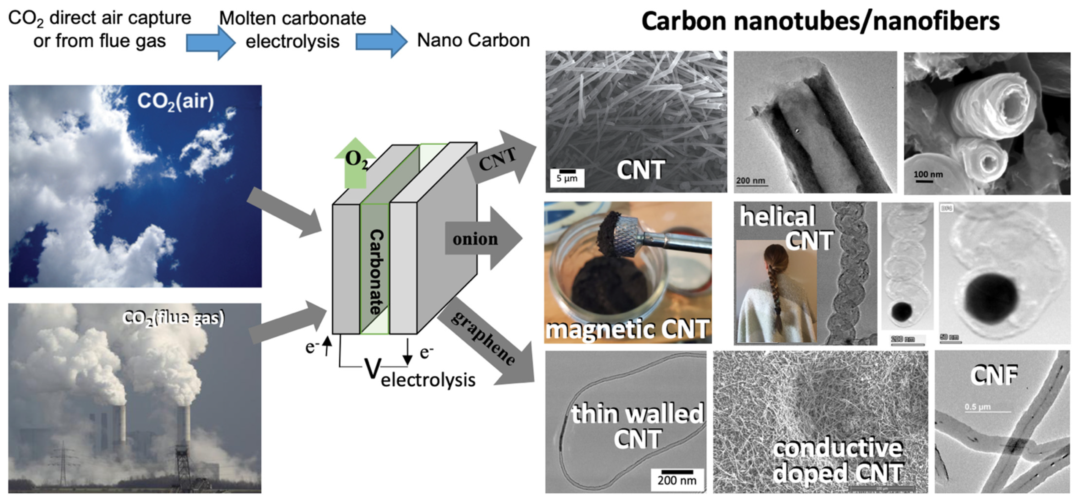
2.1. Electrolytic Conditions to Synthesize High-Purity, High-Yield CNTs from CO2
2.2. Electrolytic Conditions to Synthesize High-Purity, High-Yield CNTs from CO2
2.3. Tailored Electrochemical Growth Conditions Producing High-Aspect-Ratio CNTs from CO2
2.4. Tailored Electrochemical Growth Conditions Producing Thinner CNTs from CO2
2.5. Electrochemical Conditions to Synthesize Macroscopic Assemblies of CNTs
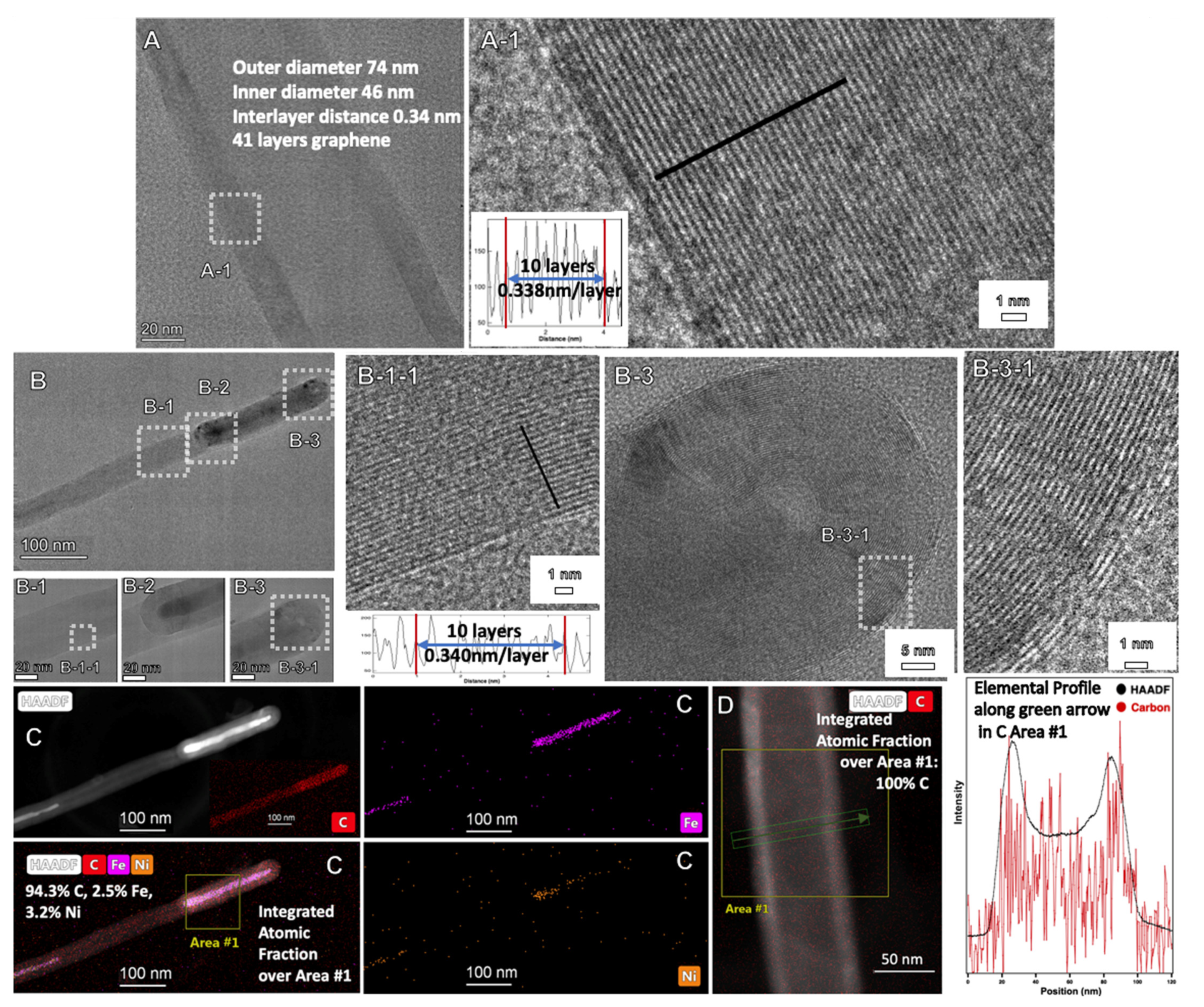
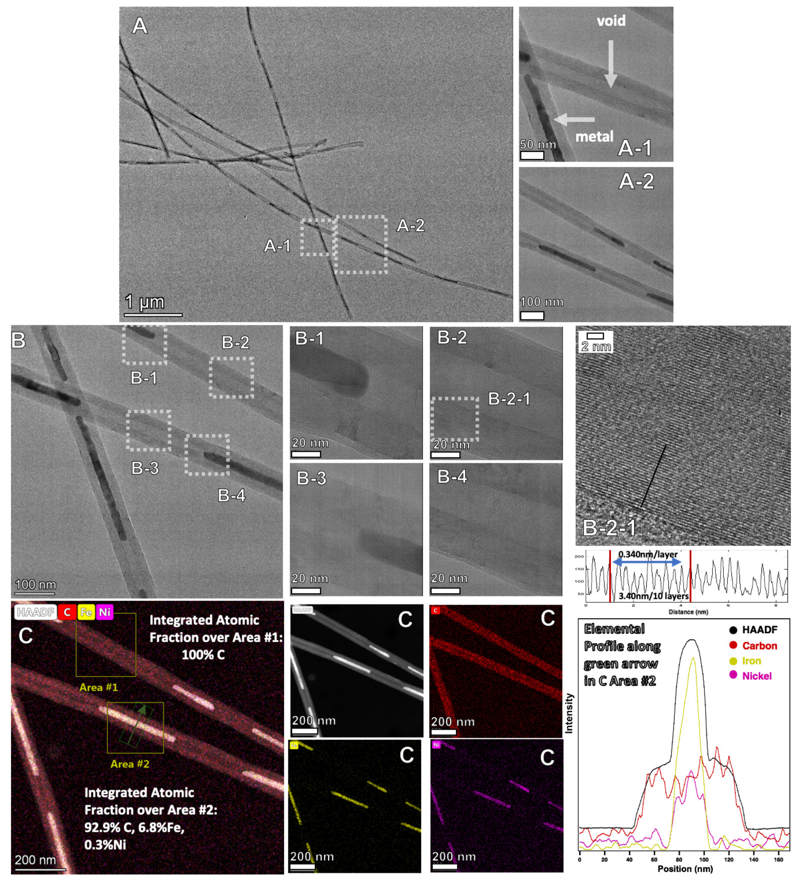
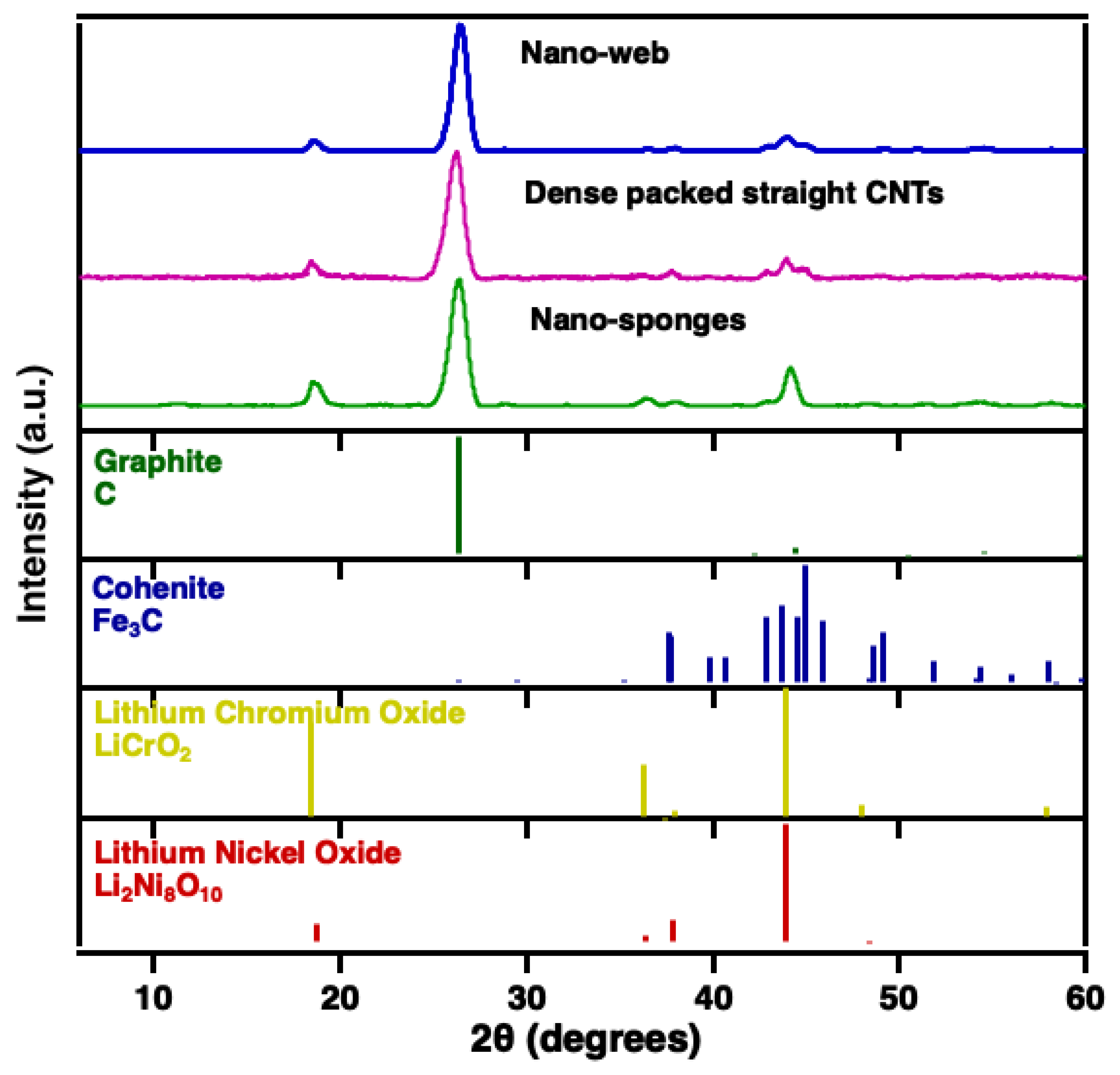
2.6. Raman and XRD Characterization of the CNTs and Their Macro-Assemblies
3. Materials and Methods
3.1. Materials
3.2. Electrolysis and Purification
3.3. Product Characterization
4. Conclusions
Author Contributions
Funding
Data Availability Statement
Conflicts of Interest
References
- CO2-Earth: Daily CO2 Values. Available online: https://www.co2.earth/daily-co2 (accessed on 7 December 2021).
- NASA: Global Climate Change: The Relentless Rise of Carbon Dioxide. Available online: https://climate.nasa.gov/climate_resources/24/ (accessed on 7 December 2021).
- Urban, M.C. Accelerating extinction risk from climate change. Science 2015, 348, 571–573. [Google Scholar] [CrossRef]
- Pimm, S.L. Climate disruption and biodiversity. Curr. Biol. 2009, 19, R595–R601. [Google Scholar] [CrossRef]
- Praksh, G.K.; Olah, G.A.; Licht, S.; Jackson, N.B. Reversing Global Warming: Chemical Recycling and Utilization of CO2. In Report of the 2008 National Science Foundation-Sponsored Workshop; University of Southern California: Los Angeles, CA, USA, 2008; Available online: https://loker.usc.edu/ReversingGlobalWarming.pdf (accessed on 7 December 2021).
- Yu, M.-F.; Lourie, O.; Dyer, M.; Moloni, K.; Kelly, T.; Ruoff, R. Strength and Breaking Mechanism of Multiwalled Carbon Nanotubes Under Tensile Load. Science 2000, 287, 637–640. [Google Scholar] [CrossRef] [PubMed]
- Chang, C.-C.; Hsu, H.-K.; Aykol, M.; Hung, W.; Chen, C.; Cronin, S. Strain-induced D band observed in carbon nanotubes. ACS Nano 2012, 5, 854–862. [Google Scholar] [CrossRef]
- Licht, S.; Liu, X.; Licht, G.; Wang, X.; Swesi, A.; Chan, Y. Amplified CO2 reduction of greenhouse gas emissions with C2CNT carbon nanotube composites. Mater. Today Sustain. 2019, 6, 100023. [Google Scholar] [CrossRef]
- Kaur, J.; Gill, G.S.; Jeet, K. Chapter 5 Applications of Carbon Nanotubes in Drug Delivery: A Comprehensive Review, in Characterization and Biology of Nanomaterials for Drug Delivery. In Characterization and Biology of Nanomaterials for Drug Delivery; Mohapatra, S.S., Ranjan, S., Dasgupta, N., Thomas, S., Eds.; Elsevier: Amsterdam, The Netherlands, 2019; Volume 1, pp. 113–135. [Google Scholar]
- Yang, H.; Xu, W.; Liang, X.; Yang, Y.; Zhou, Y. Carbon nanotubes in electrochemical, colorimetric, and fluorimetric immunosensors and immunoassays: A review. Microchim. Acta 2020, 187, 206. [Google Scholar] [CrossRef] [PubMed]
- Moghaddam, H.K.; Maraki, M.R.; Rajaei, A. Application of carbon nanotubes(CNT) on the computer science and electrical engineering: A review. Int. J. Reconfig. Embed. Syst. (IJRES) 2020, 9, 61–82. [Google Scholar] [CrossRef]
- Sehrawat, P.; Julien, C.; Islam, S.S. Carbon nanotubes in Li-ion batteries: A review. Mater. Sci. Eng. B 2016, 213, 12–40. [Google Scholar] [CrossRef]
- Han, T.; Nag, A.; Mukhopadhyay, S.C.; Xu, Y. Carbon nanotubes and its gas-sensing applications: A review. Sens. Actuators A 2019, 291, 107–143. [Google Scholar] [CrossRef]
- Kumar, S.; Pavelyev, V.; Tripathi, N.; Platonov, V.; Sharma, P.; Ahmad, R.; Mishra, P.; Khosla, A. Review—Recent Advances in the Development of Carbon Nanotubes Based Flexible Sensors. J. Electrochem. Soc. 2020, 167, 047506. [Google Scholar] [CrossRef]
- Abdullah, Z.; Othman, A.; Mwabaidur, S. Application of Carbon Nanotubes in Extraction and chromotographic analysis: A review. Arab. J. Chem. 2019, 12, 633–651. [Google Scholar]
- Basheer, B.V.; George, J.; Siengchin, S.; Parameswaranpillai, J. Polymer grafted carbon nanotubes—Synthesis, properties, and applications: A review. Nano-Struct. Nano-Objects 2020, 22, 100429. [Google Scholar] [CrossRef]
- Imtiaza, S.; Siddiqa, M.; Kausara, A.; Munthaa, S.J.; Ambreenb, I.B. A Review Featuring Fabrication, Properties and Applictions of Carbon Nanotubes (CNTs) Reinforced Polymer and Epoxy Nanocomposites. Chin. J. Polym. Sci. 2018, 36, 445–461. [Google Scholar] [CrossRef]
- Gantayata, S.; Routb, D.; Swain, S.K. Carbon Nanomaterial–Reinforced Epoxy Composites: A Review. Polym.-Plast. Technol. Eng. 2018, 57, 1–16. [Google Scholar] [CrossRef]
- Rafiquea, I.; Kausara, A.; Anwara, Z.; Muhammad, B. Exploration of Epoxy Resins, Hardening Systems, and Epoxy/Carbon Nanotube Composite Designed for High Performance Materials: A Review. Polym.-Plast. Technol. Eng. 2016, 55, 312–333. [Google Scholar] [CrossRef]
- Kausara, A.; Rafiquea, I.; Muhammad, B. Review of Applications of Polymer/Carbon Nanotubes and Epoxy/CNT Composites. Polym.-Plast. Technol. Eng. 2016, 55, 1167–1191. [Google Scholar] [CrossRef]
- Shahidi, S.; Moazzenchi, B. Carbon nanotube and its applications in textile industry—A review. J. Text. Inst. 2018, 109, 1653–1666. [Google Scholar] [CrossRef]
- Rather, S.U. Preparation, characterization and hydrogen storage studies of carbon nanotubes and their composites: A review. Int. J. Hydrogen Energy 2020, 45, 3847–5110. [Google Scholar] [CrossRef]
- Selvaraja, M.; Haia, A.; Banata, F.; Haijab, M. Application and prospects of carbon nanostructured materials in water treatment: A review. J. Water Process Eng. 2020, 33, 100996. [Google Scholar] [CrossRef]
- Bassyouni, M.; Mansi, A.E.; Elgabry, A.; Ibrahim, B.A.; Kassem, O.A.; Alhebeshy, R. Utilization of carbon nanotubes in removal of heavy metals from wastewater: A review of the CNTs’ potential and current challenges. Appl. Phys. A 2020, 126, 38. [Google Scholar] [CrossRef]
- Ghoranneviss, M.; Elahi, A.S. Review of carbon nanotubes production by thermal chemical vapor deposition technique. Mol. Cryst. Liq. Cryst. 2016, 629, 158–164. [Google Scholar] [CrossRef]
- Shah, K.A.; Tali, B.A. Synthesis of carbon nanotubes by catalytic chemical vapour deposition: A review on carbon sources, catalysts and substrates. Mater. Sci. Semicond. Process. 2016, 41, 67–82. [Google Scholar] [CrossRef]
- Khanna, V.; Bakshi, B.R.; Lee, L.J. Carbon Nanofiber Production: Life cycle energy consumption and environmental impact. J. Ind. Ecol. 2008, 12, 394–410. [Google Scholar] [CrossRef]
- Hu, L.; Song, H.; Ge, J.; Zhu, J.; Jiao, S. Capture and electrochemical conversion of CO2 to ultrathin graphite sheets in CaCl2-based melts. J. Mat. Chem. A. 2015, 3, 21211–21218. [Google Scholar] [CrossRef]
- Liang, C.; Chen, Y.; Wu, M.; Wang, K.; Zhang, W.; Gan, Y.; Huang, H.; Chen, J.; Zhang, J.; Zheng, S.; et al. Green synthesis of graphite from CO2 without graphitization process of amorphous carbon. Nat. Commun. 2021, 12, 119. [Google Scholar] [CrossRef]
- Licht, S.; Wang, B.; Ghosh, S.; Ayub, H.; Jiang, D.; Ganley, J. New solar carbon capture process: STEP carbon capture. J. Phys. Chem. Lett. 2010, 1, 2363–2368. [Google Scholar] [CrossRef]
- Ren, J.; Li, F.; Lau, J.; Gonzalez-Urbina, L.; Licht, S. One-pot synthesis of carbon nanofibers from CO2. Nano Lett. 2010, 15, 6142–6148. [Google Scholar] [CrossRef] [PubMed]
- Ren, J.; Licht, S. Tracking airborne CO2 mitigation and low cost transformation into valuable carbon nanotubes. Sci. Rep. 2016, 6, 27760. [Google Scholar] [CrossRef]
- Ren, J.; Lau, J.; Lefler, M.; Licht, S. The minimum electrolytic energy needed to convert carbon dioxide to carbon by electrolysis in carbonate melts. J. Phys. Chem. C. 2015, 119, 23342–23349. [Google Scholar] [CrossRef]
- Licht, S.; Douglas, A.; Ren, J.; Carter, R.; Lefler, M.; Pint, C.L. Carbon nanotubes produced from ambient carbon dioxide for environmentally sustainable lithium-ion and sodium ion battery anodes. ACS Cent. Sci. 2016, 2, 162–168. [Google Scholar] [CrossRef]
- Dey, G.; Ren, J.; El-Ghazawi, O.; Licht, S. How does an amalgamated Ni cathode affect carbon nanotube growth? A density functional calculation of nucleation and growth. RSC Adv. 2016, 122, 400–410. [Google Scholar]
- Ren, J.; Johnson, M.; Singhal, R.; Licht, S. Transformation of the greenhouse gas CO2 by molten electrolysis into a wide controlled selection of carbon nanotubes. J. CO2 Util. 2017, 18, 335–344. [Google Scholar] [CrossRef]
- Johnson, M.; Ren, J.; Lefler, M.; Licht, G.; Vicini, J.; Licht, S. Data on SEM, TEM and Raman spectra of doped, and wool carbon nanotubes made directly from CO2 by molten electrolysis. Data Br. 2017, 14, 592–606. [Google Scholar] [CrossRef] [PubMed]
- Johnson, M.; Ren, J.; Lefler, M.; Licht, G.; Vicini, J.; Liu, X.; Licht, S. Carbon nanotube wools made directly from CO2 by molten electrolysis: Value driven pathways to carbon dioxide greenhouse gas mitigation. Mater. Today Energy 2017, 5, 230–236. [Google Scholar] [CrossRef]
- Wang, X.; Liu, X.; Licht, G.; Wang, B.; Licht, S. Exploration of alkali cation variation on the synthesis of carbon nanotubes by electrolysis of CO2 in molten carbonates. J. CO2 Util. 2019, 18, 303–312. [Google Scholar] [CrossRef]
- Wang, X.; Licht, G.; Licht, S. Green and scalable separation and purification of carbon materials in molten salt by efficient high-temperature press filtration. Sep. Purif. Technol. 2021, 244, 117719. [Google Scholar] [CrossRef]
- Wang, X.; Sharif, F.; Liu, X.; Licht, G.; Lefer, M.; Licht, S. Magnetic carbon nanotubes: Carbide nucleated electrochemical growth of ferromagnetic CNTs. J. CO2 Util. 2020, 40, 101218. [Google Scholar] [CrossRef]
- Wang, X.; Liu, X.; Licht, G.; Licht, S. Calcium metaborate induced thin walled carbon nanotube syntheses from CO2 by molten carbonate electrolysis. Sci. Rep. 2020, 10, 15146. [Google Scholar] [CrossRef]
- Liu, X.; Licht, G.; Licht, S. The green synthesis of exceptional braided, helical carbon nanotubes and nanospiral platelets made directly from CO2. Mat. Today Chem. 2021, 22, 100529. [Google Scholar] [CrossRef]
- Liu, X.; Licht, G.; Licht, S. Data for the green synthesis of exceptional braided, helical carbon nanotubes and nano spiral platelets made directly from CO2. arXiv 2021, arXiv:2110.05398. [Google Scholar]
- Lau, J.; Dey, G.; Licht, S. Thermodynamic assessment of CO2 to carbon nanofiber transformation for carbon sequestration in a combined cycle gas or a coal power plant. Energy Convers. Manag. 2016, 122, 400–410. [Google Scholar] [CrossRef]
- Licht, S. Co-production of cement and carbon nanotubes with a carbon negative footprint. J. CO2 Util. 2017, 18, 378–389. [Google Scholar] [CrossRef]
- Liu, X.; Ren, J.; Licht, G.; Wang, X.; Licht, S. Carbon nano-onions made directly from CO2 by molten electrolysis for greenhouse gas mitigation. Adv. Sustain. Syst. 2019, 3, 1900056. [Google Scholar] [CrossRef]
- Ren, J.; Yu, A.; Peng, P.; Lefler, M.; Li, F.-F.; Licht, S. Recent advances in solar thermal electrochemical process (STEP) for carbon neutral products and high value nanocarbons. Acc. Chem. Res. 2019, 52, 3177–3187. [Google Scholar] [CrossRef] [PubMed]
- Liu, X.; Wang, X.; Licht, G.; Licht, S. Transformation of the greenhouse gas carbon dioxide to graphene. J. CO2 Util. 2020, 36, 288–294. [Google Scholar] [CrossRef]
- Wang, X.; Licht, G.; Liu, X.; Licht, S. One pot facile transformation of CO2 to an unusual 3-D nan-scaffold morphology of carbon. Sci Rep. 2020, 10, 21518. [Google Scholar] [CrossRef] [PubMed]
- Liu, X.; Licht, G.; Licht, S. Controlled Transition Metal Nucleated Growth of Unusual Carbon Allotropes by Molten Electrolysis of CO2. Catalysts 2022, 12, 125. [Google Scholar] [CrossRef]
- Gui, X.; Wei, J.; Wang, K.; Cao, A.; Zhu, H.; Jia, Y.; Shu, Q.; Wu, D. Carbon nanotube sponges. Adv. Mat. 2010, 22, 617–621. [Google Scholar] [CrossRef] [PubMed]
- Yu, S.-H. Carbon nanofiber aerogels for emergent cleanup of oil spillage and chemical leakage under harsh conditions. Sci. Rep. 2014, 4, 4079. [Google Scholar]
- Kim, K.H.; Tsui, M.N.; Islam, M.F. Graphene-Coated Carbon Nanotube Aerogels Remain Superelastic while Resisting Fatigue and Creep over −100 to +500 °C. Chem. Mater. 2017, 4, 2748–2755. [Google Scholar] [CrossRef]
- Wan, W.; Zhang, R.; Li, W.; Liu, H.; Lin, Y.; Li, L.; Zhou, Y. Graphene–carbon nanotube aerogel as an ultra-light, compressible and recyclable highly efficient absorbent for oil and dyes. Environ. Sci. Nano 2016, 3, 107–113. [Google Scholar] [CrossRef]
- Ozden, S.; Narayanan, T.N.; Tiwary, C.S.; Dong, P.; Hart, A.H.; Vajtai, R.; Ajayan, P.M. 3D macroporous solids from chemically cross-linked carbon. Small 2015, 11, 688–693. [Google Scholar] [CrossRef] [PubMed]
- Schaefer, A.; Fane, A.G.; Waite, T.D. Nanofiltration: Principles and Applications; Elsevier: Oxford, UK, 2005. [Google Scholar]
- Marchetti, P.; Jimenez Solomon, M.F.; Szekely, G.; Livingston, A.G. Molecular Separation with Organic Solvent Nanofiltration: A Critical Review. Chem. Rev. 2014, 114, 10735–10806. [Google Scholar] [CrossRef] [PubMed]
- Qu, H.; Rayabharam, A.; Wu, X.; Wang, P.; Li, Y.; Fagan, J.; Aluru, N.R.; Wang, Y. Selective filling of n-hexane in a tight nanopore. Nat Commun. 2021, 12, 310. [Google Scholar] [CrossRef]
- Hashim, D.P.; Romo-Herrera, J.M.; Muñoz Sandoval, E.; Ajayan, P.M. Covalently bonded three-dimensional carbon nanotube solids via boron induced nanojunctions. Sci. Rep. 2012, 2, 363. [Google Scholar] [CrossRef]
- Gabay, T.; Jacobs, E. Engineered self-organization of neural networks using carbon nanotube clusters. Physica A 2005, 350, 611–621. [Google Scholar] [CrossRef]
- Licht, S. Carbon Dioxide to carbon nanotube scale-up. arXiv 2017, arXiv:1710.07246. [Google Scholar]
- XPrize Foundation. Turning CO2 into Products; XPrize Foundation: Culver City, CA, USA, 2021; Available online: http://CarbonXPrize.org (accessed on 14 December 2021).
- XPrize Announces Winners with Each Team Creating Valuable Products from CO2. Available online: https://www.nrg.com/about/newsroom/2021/xprize-announces-the-two-winners-of--20m-nrg-cosia-carbon-xprize.html (accessed on 14 December 2021).


| Electrolysis | Cathode | Anode | Additives (wt% Powder) | Electr Time | Current Density A/cm2 | Product Description |
|---|---|---|---|---|---|---|
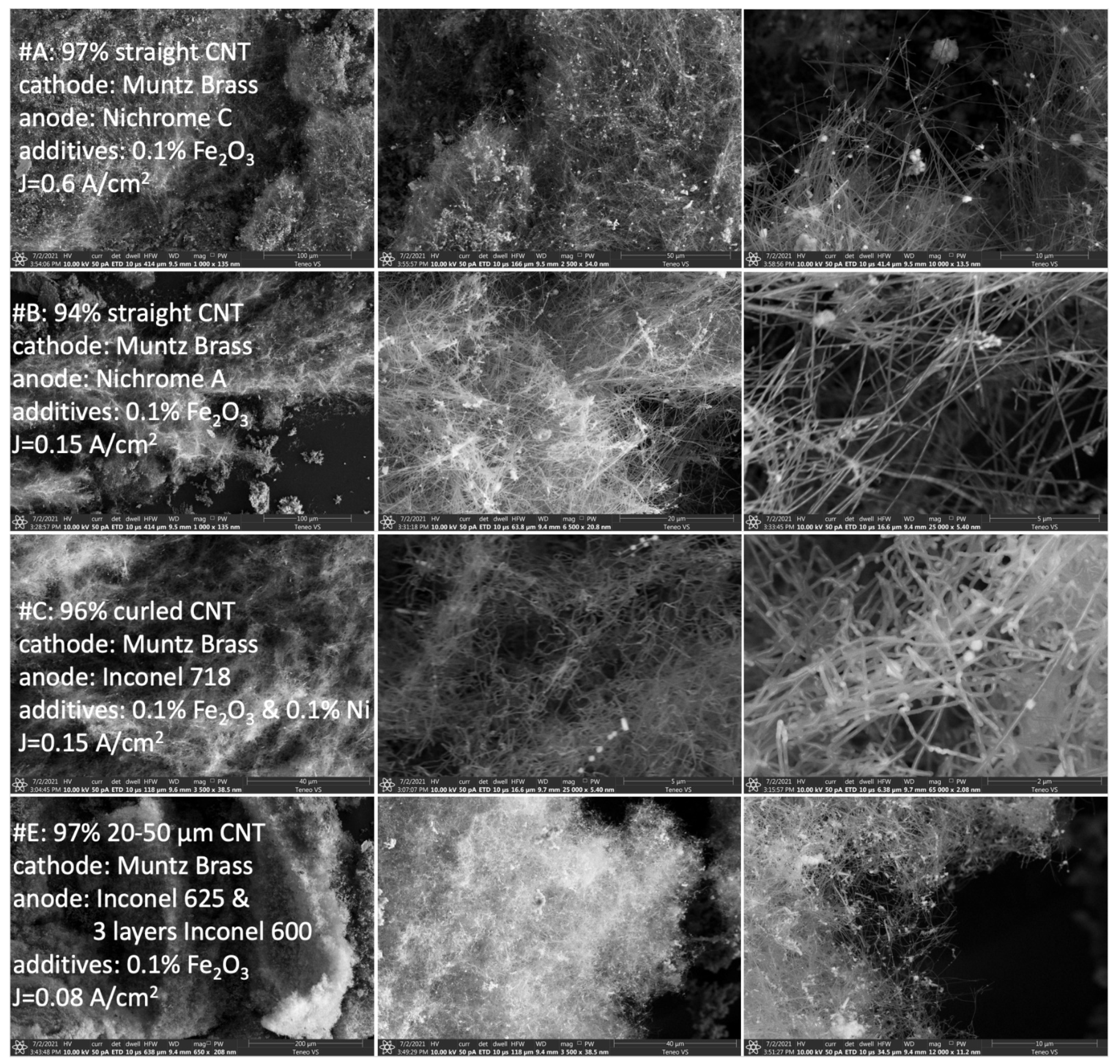
| A | Muntz Brass | Nichrome C | 0.1% Fe2O3 | 0.5 h | 0.6 | 97% Straight 50–100 µm CNT |
| B | Muntz Brass | Nichrome A | 0.1% Fe2O3 | 4 h | 0.15 | 94% Straight 20–80 µm CNT |
| C | Muntz Brass | Inconel 718 | 0.1% Fe2O3 0.1% Ni | 4 h | 0.15 | 96% curled CNT |
| D | Muntz Brass | Nichrome C | 0.1% Fe2O3 | 15 h | 0.08 | 70% 10–30 µm CNT |
| E | Muntz Brass | Inconel 625 3 layers Inconel 600 | 0.1% Fe2O3 | 15 h | 0.08 | 97% 20–50 µm CNT |
| F | Muntz Brass | Inconel 718 2 layers Inconel 600 | 0.1% Fe2O3 | 4 h | 0.15 | 98% Straight 100–500 µm CNT |
| G | Muntz Brass | Inconel 718 3 layers Inconel 600 | 0.1% Fe2O3 0.1% Ni | 15 h | 0.08 | 90% Curled CNT or fibers |
| H | Muntz Brass | Nichrome C | 0.1% Fe2O3 | 1 h | 0.4 | 96% Straight 100–200 µm CNT |
| I | Monel | Nichrome C | 0.1% Fe2O3 | 1 h | 0.4 | 97% Straight 20–50 µm CNT |
| J | Monel | Nickel | / | 2 h | 0.2 | 70% thin 10–20 µm CNT Rest: Onions |
| K | Monel | Nichrome C | 0.1% Fe2O3 | 2 h | 0.1 | 97% 30–60 µm straight CNT |
| L | Monel | Nichrome C | 0.5% Fe2O3 | 15 h | 0.08 | ~25% curled CNT ~70% straight CNT |
| M | Monel | Iridium | 0.81% Cr | 18 h | 0.08 | 97% thin 50–100 µm CNT |
| Alloy | Ni % | Fe % | Cu % | Zn % | Cr % | Mo % | Nb & Ta % |
|---|---|---|---|---|---|---|---|
| Nichrome C | 60 | 24 | 16 | ||||
| Nichrome A | 80 | 20 | |||||
| Inconel 600 | 52.5 | 18.5 | 19.0 | 3.0 | 3.6 | ||
| Inconel 718 | 72% min | 6–10 | 14–17 | ||||
| Inconel 625 | 58 | 5 max | 20–23 | 8–10 | 4.15–3.15 | ||
| Monel | 67 | 31.5 | |||||
| Muntz Brass | 60 | 40 |
| Electrolysis | Cathode | Anode | Additives (wt% Powder) | Electrolysis Time | Current Density (A/cm2) | Product Description |
|---|---|---|---|---|---|---|
| N | Nichrome C | Nichrome C | 0.81% Ni | 4 h | 0.2 | 97% nano-sponge CNT |
| F | Muntz Brass | Inconel 718 2 layers Inconel 600 | 0.1% Fe2O3 | 4 h | 0.15 | 98% dense packed straight 100–500 µm CNT |
| P | Muntz Brass | Nichrome C 3 layers Inconel 600 | 0.1% Fe2O3 | 15 h | 0.08 | 97% 50–100 µm nano-web CNT |
| Q | Monel | Nichrome C | 0.81% Ni | 3 h | 0.2 | 92% 5–30 µm nano-web CNT Rest: onions |
| CO2 Molten Electrolysis Product Description | νD (cm−1) | νG (cm−1) | ν2D (cm−1) | ID/IG | I2D/IG |
|---|---|---|---|---|---|
| Nano-web | 1342.5 | 1577 | 2689.6 | 0.28 | 0.50 |
| Dense packed CNTs | 1342.5 | 1577.4 | 2694.8 | 0.46 | 0.49 |
| Nano-sponge | 1352.5 | 1580.6 | 2687.3 | 0.67 | 0.62 |
Publisher’s Note: MDPI stays neutral with regard to jurisdictional claims in published maps and institutional affiliations. |
© 2022 by the authors. Licensee MDPI, Basel, Switzerland. This article is an open access article distributed under the terms and conditions of the Creative Commons Attribution (CC BY) license (https://creativecommons.org/licenses/by/4.0/).
Share and Cite
Liu, X.; Licht, G.; Wang, X.; Licht, S. Controlled Transition Metal Nucleated Growth of Carbon Nanotubes by Molten Electrolysis of CO2. Catalysts 2022, 12, 137. https://doi.org/10.3390/catal12020137
Liu X, Licht G, Wang X, Licht S. Controlled Transition Metal Nucleated Growth of Carbon Nanotubes by Molten Electrolysis of CO2. Catalysts. 2022; 12(2):137. https://doi.org/10.3390/catal12020137
Chicago/Turabian StyleLiu, Xinye, Gad Licht, Xirui Wang, and Stuart Licht. 2022. "Controlled Transition Metal Nucleated Growth of Carbon Nanotubes by Molten Electrolysis of CO2" Catalysts 12, no. 2: 137. https://doi.org/10.3390/catal12020137
APA StyleLiu, X., Licht, G., Wang, X., & Licht, S. (2022). Controlled Transition Metal Nucleated Growth of Carbon Nanotubes by Molten Electrolysis of CO2. Catalysts, 12(2), 137. https://doi.org/10.3390/catal12020137