Article

PT-BI Co-Deposit Shell on AU Nanoparticle Core: High Performance and Long Durability for Formic Acid Oxidation

1
Department of Chemistry, Chungnam National University, Daejeon 34134, Korea
2
Jeonju Center, Korea Basic Science Institute, Jeonju 54907, Korea
*
Author to whom correspondence should be addressed.
Catalysts 2021, 11(9), 1049; https://doi.org/10.3390/catal11091049
Submission received: 22 June 2021 / Revised: 19 August 2021 / Accepted: 26 August 2021 / Published: 30 August 2021
(This article belongs to the Special Issue Structured Materials for Catalytic Applications)

Abstract

:
This work presents the catalysts of Pt-Bi shells on Au nanoparticle cores and Pt overlayers on the Pt-Bi shells toward formic acid oxidation (FAO). Pt and Bi were co-deposited on Au nanoparticles (Au NP) via the irreversible adsorption method using a mixed precursor solution of Pt and Bi ions, and the amount of the co-deposits was controlled with the repetition of the deposition cycle. Rinsing of the co-adsorbed ionic layers of Pt and Bi with a H2SO4 solution selectively removed the Bi ions to leave Pt-rich and Bi-lean (<0.4 atomic %) co-deposits on Au NP (Pt-Bi/Au NP), conceptually similar to de-alloying. Additional Pt was deposited over Pt-Bi/Au NPs (Pt/Pt-Bi/Au NPs) to manipulate further the physicochemical properties of Pt-Bi/Au NPs. Transmission electron microscopy revealed the core–shell structures of Pt-Bi/Au NPs and Pt/Pt-Bi/Au NPs, whose shell thickness ranged from roughly four to six atomic layers. Moreover, the low crystallinity of the Pt-containing shells was confirmed with X-ray diffraction. Electrochemical studies showed that the surfaces of Pt-Bi/Au NPs were characterized by low hydrogen adsorption abilities, which increased after the deposition of additional Pt. Durability tests were carried out with 1000 voltammetric cycles between −0.26 and 0.4 V (versus Ag/AgCl) in a solution of 1.0 M HCOOH + 0.1 M H2SO4. The initial averaged FAO performance on Pt-Bi/Au NPs and Pt/Pt-Bi/Au NPs (0.11 ± 0.01 A/mg, normalized to the catalyst weight) was higher than that of a commercial Pt nanoparticle catalyst (Pt NP, 0.023 A/mg) by a factor of ~5, mainly due to enhancement of dehydrogenation and suppression of dehydration. The catalytic activity of Pt/Pt-Bi/Au NP (0.04 ± 0.01 A/mg) in the 1000th cycle was greater than that of Pt-Bi/Au NP (0.026 ± 0.003 A/mg) and that of Pt NP (0.006 A/mg). The reason for the higher durability was suggested to be the low mobility of surface Pt atoms on the investigated catalysts.

Graphical Abstract

1. Introduction

Recent technical developments in the conversion of CO2 to formic acid have directed the attention of researchers toward the development of direct formic acid fuel cells (DFAFCs) for portable devices and power sources at off-grid locations [1,2,3,4,5,6,7,8,9,10,11,12,13,14,15].
The most intensively investigated electrochemical catalysts for formic acid oxidation (FAO) are Pt- and Pd-based ones [16,17,18,19,20,21,22,23,24,25,26,27,28]. FAO takes place on such metal surfaces in a dual path mechanism [29,30,31,32,33]: a dehydrogenation path to directly oxidize formic acid to CO2 and H+ to produce two electrons (HCOOH → CO2 + 2H+ + 2e) and a dehydration path to dissociate formic acid to poisonous CO (HCOOH → H2O + CO), which is electrochemically oxidized to CO2 (CO + H2O → CO2 + 2H+ + 2e) at a high potential. Therefore, the development of more efficient FAO electrochemical catalysts has been focused on the suppression of dehydration and enhancement of dehydrogenation. The general way to achieve this specific goal is to manipulate the physicochemical properties of Pt or Pd metals by alloying with other secondary metals such as Ni, Au, Bi, Pb, As and Sb [34,35,36,37,38,39,40,41,42,43,44] or by attaching secondary metals on their surfaces [45,46,47,48,49,50,51,52,53,54,55,56].
One of the typical examples is bi-metallic catalysts of Pt and Au, which are highly selective to the dehydrogenation path of FAO [57,58,59,60,61,62,63,64,65,66,67,68,69,70,71,72,73,74,75]. The FAO efficiencies of the dehydrogenation path on Pt-Au alloys have been reported to increase significantly. For example, a Pt4Au96 nanoparticle catalyst [70] and de-alloyed Au0.27Cu0.70Pt0.03 nanoporous catalyst [73] demonstrated two orders of magnitude greater activity than a commercial Pt catalyst in terms of Pt mass. On the other hand, Pt deposits on Au were found to enhance FAO. Specifically, when the fractions of Pt deposits were small (~0.2 in coverage) and the deposit sizes were less than 10 nm, the dehydrogenation path was promoted, with the inhibition of poison formation [57]. On the other hand, Pt flecks (or discrete Pt deposits) on Au nanoparticles were more active toward FAO than Pt shells on Au nanoparticle cores, and the FAO activity of Pt flecks increased as the size of the Au nanoparticles decreased [58,62]. Furthermore, the FAO oxidation efficiency on Pt deposits on Au was demonstrated to depend strongly on the shapes and coverage of the Pt deposits [76]. The enhancement of FAO on Pt-Au catalysts was interpreted in terms of an ensemble effect or electronic effect.
Modification of Pt surfaces with Bi is also known to enhance FAO performance. When Pt nanoparticles and Pt deposits on Au nanoparticles were modified with Bi using the irreversible adsorption method, for instance, the FAO activities were demonstrated to be enhanced by factor of 5 [71]. An additional FAO path (named the “oxidized surface path”) on the Bi-modified Pt surface was reported to be operational at a potential higher than that of dehydrogenation [77]. On the other hand, a DFAFC stack of 35 membrane electrode assemblies yielding a power of 300 W was realized with a mass production of Bi-modified Pt nanoparticles [78]. From this particular point of view, the modification of Pt surfaces with Bi would be a certain advance toward practical DFAFCs.
The durability of an electrochemical catalyst for FAO is another critical issue, especially regarding the commercialization of DFAFCs. Dispersed Pt in Au, especially at the levels of a few atomic %, demonstrated high FAO performance and slow decay rates attributed to the slow loss of Pt [73], robustness of Pt ensembles [65] or movement of Pt to larger domains [72]. Recently, our group reported that Pt overlayers additionally deposited on Bi-modified Pt surfaces retarded the oxidative removal of Bi to increase not only the catalytic durability but also the performance [77]. However, a direct comparison of the published stabilities for FAO is practically impossible due to the absence of a unified evaluation protocol.
This work presents Pt-Bi co-deposit shells on Au nanoparticle cores toward high FAO performance and long durability. The Pt-Bi shells were produced via co-deposition of Pt and Bi using the irreversible adsorption method [79]. The presence of Bi enhanced the irreversible adsorption of Pt on Au during the co-adsorption of Pt and Bi, and the following rinsing step removed most of the co-adsorbed Bi to leave thick Pt-rich and Bi-lean shells. The surfaces of such Pt-Bi shells were highly active and durable toward FAO. Furthermore, the additional deposition of Pt over the Pt-Bi shells on the Au nanoparticle cores further improved the catalytic durability. The observed unique catalytic behavior of the Pt-Bi co-deposit shells on Au nanoparticle cores is discussed in contrast to thin and discrete Pt deposits (without Bi) on Au [71].

2. Results and Discussion

2.1. Structural Analysis

Figure 1 demonstrates the particle size variations of Pt-Bi/Au NPs and Pt/Pt-Bi/Au NPs as a function of the number of co-deposition cycles. The average particle sizes were extracted using the particle size distributions measured with TEM (Figure S1). The particle sizes of Pt-Bi/Au NPs certainly increase as the co-deposition cycle is repeated. For instance, the particle size of a plain Au NP (4.2 ± 1.7 nm) increases to 6.7 ± 2.2 nm after the fifth co-deposition cycle, i.e., the size of Pt-Bi(5)/Au NP. This specific size increment of ~2.5 nm roughly corresponds to the thickness of four or five atomic layers on the Au NP, which is more or less similar to that of Pt-Bi co-deposits on a Au disk (six to seven layers) prepared using an identical procedure of co-deposition but with rinsing with water [79]. On the other hand, the sequential deposition of Pt over Pt-Bi co-deposits further increases the particle sizes. Specifically, the thickness of the additional Pt layer on Pt/Pt-Bi(1)/Au NP corresponds to three atomic layers approximately, while that on Pt/Pt-Bi(5) Au NP is slightly less than two layers. Thus, the thickness of Pt-containing layers on Pt/Pt-Bi/Au NPs spans roughly from four to six atomic layers.
Figure 2 presents STEM measurements of Pt-Bi(3)/Au NP and Pt/Pt-Bi(3)/Au NP. Figure 2a illustrates the elemental mapping images of Pt and Au in Pt-Bi(3)/Au NP, clearly revealing that the mapping area of Pt is larger than that of Au. In the line profile of Pt-Bi(3)/Au NP (Figure 2b), furthermore, Pt is consistently observable at the surface of Au. However, no detection of Bi indicates that the Bi amount in Pt-Bi co-deposits would be below the detection limit of EDS (see below for detailed discussions). Likewise, the STEM features of Pt/Pt-Bi(3)/Au NP are similar to those of Pt-Bi(3)/Au NP, i.e., the larger Pt area than the Au area in the elemental maps (Figure 2c) and the existence of Pt on the surface of Au in the line profile (Figure 2d). Thus, the core–shell structures of Pt-Bi/Au NPs and Pt/Pt-Bi/Au NPs are verified.
Figure 3 compares the XRD patterns of Au NP, Pt-Bi(3)/Au NP, Pt/Pt-Bi(3)/Au NP and Pt/C. A comparison of the diffraction peaks of Pt-Bi(3)/Au NP and Pt/Pt-Bi(3)/Au NP with those of Au NP and Pt/C (the respective reference materials for Au and Pt) immediately indicates that there are two components for Au and Pt. For instance, the asymmetric peak at 38.3° of Pt-Bi(3)/Au NP clearly consists of one component at 38.2° for Au(111) and another one at 39.8° for Pt(111). However, the peaks for Pt are not so sharp, implying that the Pt-Bi and Pt/Pt-Bi shells are poorly crystallized despite comparable amounts of Pt and Au (see below). XRD peaks for Bi are not present either. Estimation of the sizes using the peak widths without de-convolution reveals that the particle sizes at the right-hand side of Figure 3 are fairly consistent with those in Figure 1.

2.2. Compositional Analysis

Figure 4a represents the variations in the Pt/Au and Bi/Au atomic ratios of Pt-Bi/Au NPs and Pt/Pt-Bi/Au NPs obtained using ICP-AES. The dotted lines for Pt-Bi/Au NPs demonstrate that as the co-deposition cycle is repeated, the ratio of Pt/Au increases rapidly while that of Bi/Au practically remains constant. The atomic ratios of Bi to Pt, i.e., ((Bi/Au)/(Pt/Au)), are less than 0.004 for all the Pt-Bi/Au NPs, significantly low considering that the Bi amount in Pt-Bi co-deposits on the Au disk (Pt-Bi/Au disk) was in the range of 0.1~0.2 of Pt [79]. The only difference in the preparation of Pt-Bi/Au NP in this work and the Pt-Bi/Au disk in our previous work is in the rinsing medium used immediately after the co-adsorption of Pt and Bi precursor ions (i.e., 0.5 M H2SO4 solution in this work versus water in the previous work). To scrutinize the role of the rinsing medium, the Pt/Au and Bi/Au ratios of two different Pt-Bi(1)/Au NPs rinsed, respectively, with water and 0.5 M H2SO4 solution are compared. The Pt/Au and Bi/Au ratios are found to be ~0.24 and ~0.04 for the water rinse and ~0.3 and ~0.002 for the H2SO4 solution rinse, suggesting that water removes the adsorbed Pt precursor ions moderately, while H2SO4 solution eliminates the adsorbed Bi precursor ions significantly (see Figure S2, Supporting Information). In the case of a Pt ionic layer on Au NP formed in 1 mM solution of Pt without Bi (i.e., Pt/Au NP), meanwhile, the Pt/Au ratio is ~0.2 regardless of the rinsing medium, implying that the amount of adsorbed Pt ions on Au NP, without co-adsorbed Bi ions, is irrelevant to the rinsing medium. Furthermore, the higher Pt/Au ratio (~0.3) of Pt-Bi(1)/Au NP after the H2SO4 solution rinse than that (~0.2) of Pt(1)/Au NP suggests that the Bi ions in the precursor solution enhance the adsorption of Pt ions during co-deposition [79]. Therefore, the H2SO4 solution rinse step causes the selective removal of the Bi ions from the mixed ionic layers on Au NPs, and the following chemical reduction step leaves thick Pt layers containing Bi at a trace level (<~0.4 atomic %). The Bi at such trace levels in Pt-Bi deposits is certainly measurable with ICP-AES (the detection limit for Bi is 50 ppm weight [80]), but not detectable with EDS and XRD (the normal detection limits are a few %). The selective removal of Bi from the co-adsorbed ionic layers of Pt and Bi would be conceptually similar to the de-alloying of Pt-M (e.g., M = Ag, Cu) alloys to produce Pt-rich layers [81,82,83]. Despite the extremely low contents of Bi in Pt-Bi deposits, this work is focused on H2SO4-rinsed Pt-Bi/Au NPs because their observed FAO efficiencies are superior, as presented below. On the other hand, the solid lines in Figure 4a indicate that the sequential deposition of Pt over Pt-Bi/Au NPs increases the Pt/Au ratio with the fairly constant Bi/Au ratios. The Pt/Au ratio ranges from ~0.3 for Pt-Bi(1)/Au NP to ~1.3 for Pt/Pt-Bi(5)/Au NP, indicating that the deposited amount of Pt is quite significant.
Figure 4b compares typical XPS spectra of Pt and Bi in Pt-Bi(2)/Au NP. The Au 4f peaks at 84.0 and 87.7 eV are intense and sharp enough to indicate that the Au NP is metallic, while the Pt 4f peaks at 71.1 and 74.4 eV are broad, implying that the Pt in Pt-Bi co-deposits is a mixture of metal and oxide. A semi-quantitative XPS analysis of Pt reveals that the variations in the Pt/Au atomic ratios in Pt-Bi/Au NPs and Pt/Pt-Bi/Au NPs (not shown here) are similar to those presented in Figure 4a. However, the peaks for Bi are hardly discernible, suggesting that the amount of Bi in Pt-Bi(2)/Au NP is only slightly above the detection limit of XPS (theoretically suggested one is 0.3 atomic % in a Pt matrix [84]). Thus, the existence of Bi in Pt-Bi co-deposits is confirmed; however, a further quantitative analysis of Bi would be meaningless because the quantitative analysis limit is generally higher than the qualitative detection limit.
The structural and compositional results presented so far clearly evidence that the Pt-Bi/Au NPs prepared via the rinse step with a H2SO4 solution are the Pt-Bi co-deposit shells covering Au NP cores and that Pt/Pt-Bi/Au NPs are the Pt-Bi/Au NPs wrapped with additional Pt shells. The Pt-Bi co-deposit shells are rich in Pt but lean in Bi at trace levels (<0.4%), and the Pt-containing shells are poorly crystallized.

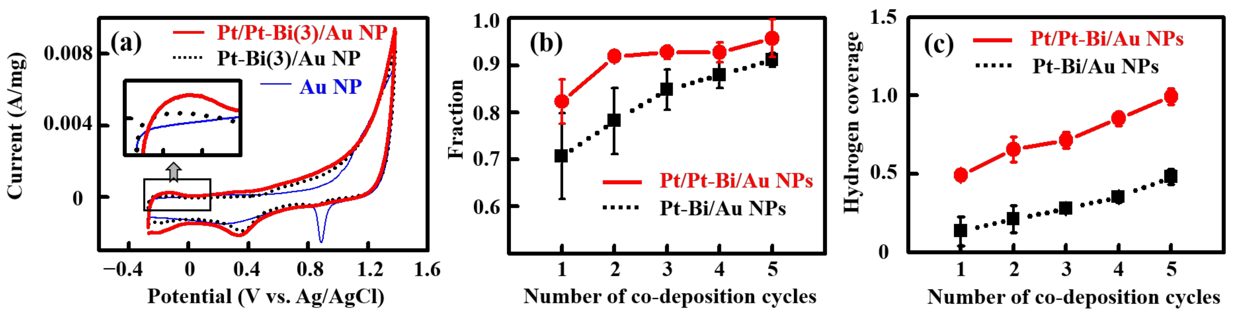
2.3. Electrochemical Behavior
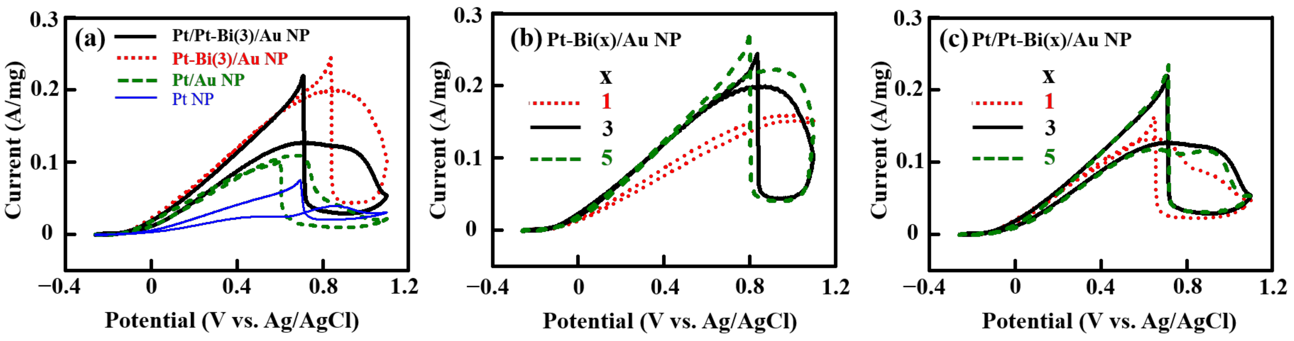
Figure 5a compares the voltammograms of plain Au NP, Pt-Bi(3)/Au NP and Pt/Pt-Bi(3)/Au NP in 0.1 M H2SO4 solution. In the thin solid line voltammogram of Au NP, oxidation of Au and carbon initiates at ~0.8 V in the positive-going scan, and the corresponding reduction peaks appear at ~0.9 and ~0.3 V in the reverse scan. The Pt-Bi co-deposits on Au NP modify the voltammogram to the dotted line one. Specifically, the presence of the co-deposits lowers the surface oxidation onset potential to ~0.4 V, and an additional reduction current peak ascribable to the reduction in co-deposit oxides emerges at ~0.4 V. A distinctive Bi oxidation peak (normally at ~0.6 V [71,85]) is not discernible, coherently supporting that the Bi amount is quite low. On the other hand, the decreased reduction charge of Au oxide indicates that most of the Au surface is covered with the co-deposits. The subsequent deposition of Pt on Pt/Pt-Bi/Au NP further fortifies the features of Pt, as denoted in the voltammogram by the thick solid line. In particular, the charge in the hydrogen region increases significantly (the inset of Figure 5a).
Figure 5b displays the fraction of the Au surface covered by co-deposits as a function of the number of co-deposition cycles. The fraction of covered Au surface was estimated using a ratio of the Au oxide reduction charge of a Pt-Bi/Au NP or Pt/Pt-Bi/Au NP to that of the plain Au NP. Figure 5b reveals that the fraction of covered Au surface of Pt-Bi/Au NP increases from ~0.7 to ~0.9 as the co-deposition cycle is repeated. After the subsequent deposition of Pt, the further increases in fraction support the notion that additionally deposited Pt resides simultaneously on the pre-existing co-deposits and the uncovered Au surfaces (most likely in small spaces between the co-deposits). On the other hand, the hydrogen coverage of Pt-Bi/Au NP (Figure 5c) certainly increases as the co-deposition cycle is repeated; moreover, the subsequent deposition of Pt on Pt-Bi/Au NPs increases the hydrogen coverage significantly. Despite a qualitative similarity between the variations in hydrogen coverage and the Pt/Au ratios, the hydrogen coverage of Pt-Bi/Au NPs and Pt/Pt-Bi/Au NPs is worth discussing quantitatively in detail. For instance, the fraction of the covered Au surface of Pt-Bi(3)/Au NP is ~0.8, which would be the value of hydrogen coverage if the hydrogen adsorption stoichiometry is 1, neglecting the influence of Bi to Pt in hydrogen adsorption (due to a trace level amount of Bi). However, the observed hydrogen coverage is ~0.3, suggesting that the hydrogen adsorption stoichiometry of Pt-Bi(3)/Au NP is apparently ~0.4 (≈ 0.3/0.8). The hydrogen adsorption stoichiometries of Pt-Bi/Au NPs, estimated in this way, range from 0.2 to 0.5, while those of Pt/Pt-Bi/Au NPs span from 0.6 to 1.0. Deviation in the hydrogen adsorption stoichiometry of Pt from the conventionally accepted value of 1 was demonstrated on Pt deposit model catalysts on Au, whose shapes and populations were controlled [86]. Specifically, the hydrogen adsorption stoichiometry on the atomically rough stepped surfaces of cone-shaped Pt deposits on the Au disk was reported to be 0.5. It is possible that the severe removal of Bi during H2SO4 solution rinse may give rise to the development of poorly crystallized Pt-Bi deposits of quite rough surfaces in atomic scale, resulting in poorly coordinated surface Pt atoms, reducing the hydrogen adsorption stoichiometry. The subsequent deposition of Pt on Pt-Bi(3)/Au NP increases the hydrogen coverage from ~0.3 to ~0.7 (Figure 5c). The particular increment of 0.4 would not indicate an increase in the number of surface Pt atoms; rather, the subsequently deposited Pt on the rough surfaces would increase the coordination number of the surface Pt atoms to raise the hydrogen adsorption stoichiometry. In the aspect of hydrogen adsorption, therefore, the surfaces of Pt-Bi/Au NPs are quite distinctive, even though such rough surfaces of the Pt-Bi shells are not yet visually accessible. Recalling that the irreversible adsorption of Pt does not occur on plain Pt NP [77], the subsequent deposition of Pt on Pt-Bi/Au NPs via irreversible adsorption is indirect evidence of the uniqueness of the poorly crystallized Pt-Bi shell surfaces having poorly coordinated Pt atoms.

2.4. FAO Behavior

Figure 6a compares the FAO behaviors of Pt NP, Pt/Au NP, Pt-Bi(3)/Au NP and Pt/Pt-Bi(3)/Au NP. The thin line voltammogram of Pt NP demonstrates the typical FAO paths of dehydration and dehydrogenation. Specifically, the oxidation peaks at ~0.4 and ~0.9 V in the positive-going scan denote the currents of dehydrogenation and poison oxidation from dehydration, respectively; in the following reverse scan, the current leading edge near 0.7 V indicates the activation of dehydrogenation on the poison-free Pt NP surface. In the dashed line voltammogram of Pt/Au NP, Pt deposits (or ensembles) on Au enhance the dehydrogenation path and simultaneously suppress the dehydration path [85] to increase the FAO current. The dotted line voltammogram of Pt-Bi(3)/Au NP differs from the previous ones. In the positive-going scan, there is a huge and broad oxidation peak at ~1.0 V, consisting of an FAO peak in the dehydrogenation path (below ~0.7 V) and an FAO peak in the oxidized surface path (typically in the potential range of 0.4–1.2 V) [77]. In the following reverse potential excursion, the FAO current leading edge at ~0.9 V reveals the activation of the dehydrogenation path on the Pt-Bi shells. The FAO behavior of Pt-Bi(3)/Au NP is quite distinct in three aspects. The first one is that the FAO current on Pt-Bi(3)/Au NP below 0.7 V (mostly via the dehydrogenation path) is much higher than those of Pt NP and Pt/Au NP, supporting more efficient dehydrogenation on Pt-Bi(3)/Au NP. The second aspect is the steep current rise in the negative-going scan on Pt-Bi/Au NP. The current profiles of the dehydrogenation path on the Pt-Bi/Au disk (Pt-Bi co-deposits on Au disk) [79] and Bi/Pt NP (Bi-modified Pt NP) [77] in the negative-going scan are bell-shaped peaks with the enhancement of FAO. Indeed, the current leading edge is a characteristic of plain Pt NP, implying that the Pt-Bi co-deposits are apparently Pt-like in this particular point of view. The third aspect is the huge peak via the oxidized surface path at ~1.0 V in the positive-going scan. The activation of the oxidized surface path is quite a distinctive feature of Pt surfaces modified by significant amounts of Bi more than 0.2 in coverage [71] or Pt overlayers on Bi-modified Pt NP [77]; in fact, the oxidized surface path is not operational at all on plain Pt surfaces. Due to the trace amount of Bi in the Pt-Bi shells, the poorly crystallized surfaces of Pt-Bi shells are likely responsible for such a huge FAO current of the oxidized surface path. Thus, the rough surfaces of the Pt-Bi co-deposits, characterized by low hydrogen adsorption stoichiometries, promote the FAO paths of dehydrogenation and oxidized surface with simultaneous suppression of the dehydration path. On the other hand, the thick solid line voltammogram of Pt/Pt-Bi(3)/Au NP in Figure 6a is similar to that of Pt-Bi(3)/Au NP in shape. However, the FAO currents of the dehydrogenation and oxidized surface paths in the positive-going scan are slightly lower than those of Pt-Bi(3)/Au NP, while the potential of the current leading edge in the negative-going scan shifts to ~0.7 V. Additional deposition of Pt certainly reduces the density of the poorly coordinated Pt atoms on the Pt-Bi surfaces but significantly sustains the unique FAO features of the Pt-Bi surfaces.
Figure 6b shows the typical FAO behaviors of Pt-Bi/Au NPs to demonstrate a dependency on the number of co-deposition cycles. The dotted line current profile of Pt-Bi(1)/Au NP seriously differs from those of Pt-Bi(3)/Au NP and Pt-Bi(5)/Au NP, both of which are very similar to each other. On Pt-Bi(1)/Au NP, the FAO currents via the paths of dehydrogenation and oxidized surface, including the current leading edge, are not yet fully developed; however, an additional deposition of Pt, i.e., Pt/Pt-Bi(1)/Au NP, results in a voltammogram similar to that of Pt-Bi(3)/Au NP but smaller in current (Figure 6c). Thus, the observation of the FAO features described in conjunction with Figure 6a would need a critical amount of Pt, at least more than a Pt/Au ratio of 0.5 (Figure 4a).
Figure 6 clearly supports a correlation of the FAO enhancement of Pt-Bi/Au NPs and Pt/Pt-Bi/Au NPs to the poorly crystallized Pt-Bi shells. Three causes for the catalytic improvements associated with the Pt-Bi shells are conceivable: the interaction between Pt and Au, the influence of Bi to Pt, and the poorly coordinated surface Pt atoms. First, the Pt-Au systems of alloys or modified surfaces have been known to enhance FAO via the ensemble and/or electronic effects [60,62,63,65,67,68,69,70,72,73,74,75]. However, the Pt-Bi shells in this work are too thick, so the surface Pt atoms cannot interact with the Au NP cores. On the other hand, the modification of Pt with Bi was reported to be boosted significantly when the amount of Bi was high [40,85,87]. For example, in the cases of Bi-modified Pt surfaces, the lower limit of Bi was 0.2 in coverage [85]; in the cases of the alloy, substantial catalytic improvements were observed when the Bi content was from ~30% to ~150% [40,87,88,89]. In this work, the Bi amount (<0.4%) in the Pt-Bi shells is too low to modify the surrounding Pt, so a role of Bi should be disregarded regarding FAO enhancement. The only possible option would be the poorly coordinated surface Pt atoms, featured by low hydrogen adsorption stoichiometries. Some aggregates of a few poorly coordinated Pt atoms on the rough surfaces of the poorly crystalized Pt-Bi shell may play the role of Pt ensembles, similar to the Pt atoms dispersed in an inert Au matrix [63,70]. The sequential deposition of Pt onto the Pt-Bi shells does not remove such aggregates completely, thus sustaining the high FAO performance.
One may argue that the observations in this work may be inconsistent with the superior FAO performance of Pt flecks to Pt shells [58,62]. The difference in Pt deposition methods may be important in understanding this inconsistency. In this work, the Pt-Bi shells were produced after the removal of Bi from the mixed ionic layers of Pt and Bi, while, in the cited literature, the Pt flecks or shells were formed via hydrogen reduction. The latter method is a sort of building-up process, which would result in Pt deposits of a quite different structure from the suggested structure in this work. We believe that the differences in Pt structures would lead to the inconsistency in FAO performance.

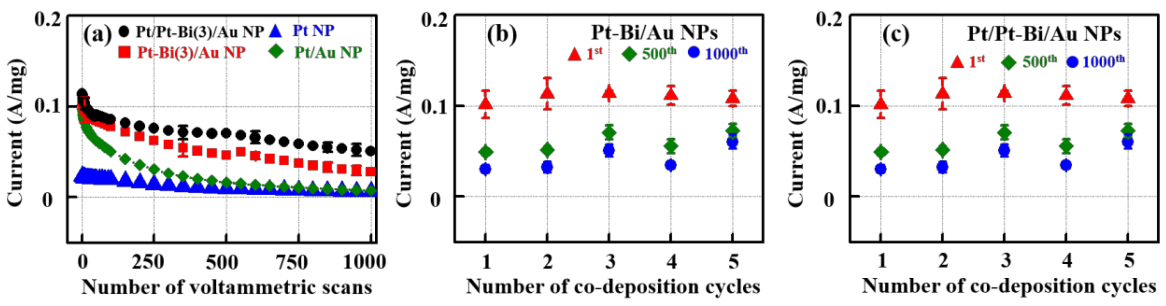
2.5. Current Decays in Various FAO Catalysts

Figure 7 compares the current decays of Pt NP, Pt/Au NP, Bi/Pt NPs and Pt/Bi/Pt NPs in FAO. Specifically, the presented currents in Figure 7 are the maximum FAO currents observed during a voltammetric cycle between −0.26 and 0.4 V in 1.0 M HCOOH + 0.1 M H2SO4. The FAO voltammograms of the 1st and 1000th cycles of the investigated catalysts are presented in Figure S3, Supporting Information. The choice of 0.4 V as the upper scan limit is for two reasons [71,78]: only the dehydrogenation route is to active below 0.4 V, and the oxidative removal of Bi in Bi-modified Pt, if any, is anticipated to be minimal.
Figure 7a demonstrates the FAO current variations as a function of the number of voltammetric cycles. The general FAO current decay pattern shows a fast decline during the first one hundred cycles, followed by a slow decrease. However, the currents in the 1st and 1000th cycles depend significantly on the types of catalysts. The FAO currents in the 1st and 1000th cycles clearly prove that Pt/Pt-Bi(3)/Au NP is the most desirable catalyst among the catalysts presented in Figure 7a. Specifically, the initial and final currents of Pt/Pt-Bi(3)/Au NP are 0.113 and 0.054 A/mg, respectively, which are higher roughly by the factors of 5 and 9 than those of Pt NP (0.023 and 0.006 A/mg). The FAO current of Pt-Bi(3)/Au NP declines slightly faster from the initial value of 0.105 A/mg to the final one of 0.029 A/mg (but still higher by the factor of 5 than that of Pt NP). Therefore, the FAO current decay on Pt-Bi(3)/Au NP would be related to the decrease in the density of poorly coordinated Pt atoms during the continuous FAO cycles, most likely due to movement of Pt atoms. Then, the Pt overlayer on Pt-Bi(3)/Au NP, although decreasing the density of the poorly coordinated Pt atoms, is likely to prohibit the movement of Pt atoms to reduce the decay rate or to maintain higher FAO performance.
This FAO decay behavior of Pt-Bi(3)/Au NP and Pt/Pt-Bi(3)/Au NP should be distinguished from that of Bi-modified Pt catalysts. As explained previously, the Bi-rich Pt-Bi(3)/Au NP prepared using a water rinse contrasts the Bi-lean Pt-Bi(3)/Au NP produced using a H2SO4 rinse. On a Bi-rich Pt-Bi/Au NP, the FAO decays rapidly from 0.088 to 0.010 A/mg, although not shown here. On the other hand, Pt/Bi/Pt NP, i.e., with an additionally deposited Pt overlayer on Bi-modified Pt NP, is worthy of comparison [77]. The FAO current on Pt/Bi/Pt NP declined from 0.048 to 0.024 A/mg in 0.5 M HCOOH + 0.1 M H2SO4 solution, proving that Pt/Bi/Pt NP was inferior to Pt-Bi(3)/Au NP and Pt/Pt-Bi(3)/Au NP, although certainly superior to Pt NP and Bi/Pt NP. The fast FAO current decay behavior of Bi-rich Pt-Bi(3)/Au NP and Pt/Bi/Pt NP was certainly ascribed to the removal of Bi during the current decay measurements, which is not the case for Pt-Bi(3)/Au NP and Pt/Pt-Bi(3)/Au NP. In fact, XPS measurements after the 1000th cycle reveal that the initial amounts of Bi in Pt-Bi/Au NPs and Pt/Pt-Bi/Au NPs are conserved.
Figure 7b,c summarize the FAO current variations of Pt-Bi/Au NPs and Pt/Pt-Bi/Au NPs. As demonstrated in Figure 7b, the FAO currents of Pt-Bi/Au NPs in the first cycle are similar to each other within experimental uncertainties, regardless of the number of co-deposition cycles, and the rather wide deviations denote a difficulty in the control of the Pt-Bi/Au NPs in a precise manner. The FAO currents in the 500th voltammetric scan decrease to the level of ~0.04 A/mg, and those in the 1000th cycle become fairly constant at a value of 0.027 A/mg on average. In particular, the small deviations in the 1000th cycle certainly indicate that, during the FAO cycling, the surfaces of Pt-Bi/Au NPs converge to a certain state regardless of the number of co-deposition cycles. On the other hand, the FAO currents of Pt/Pt-Bi/Au NPs (Figure 7c) in the first cycle are also relatively similar to each other and comparable to those of Pt-Bi/Au NPs; moreover, the uncertainties are relatively smaller, supporting the idea that the surfaces of Pt/Pt-Bi/Au NPs are more controllable. The FAO currents in the 1000th cycle become 0.042 A/mg on average, higher than those of Pt-Bi/Au NPs (0.026 A/mg) and much better than that of Pt NP by a factor of 7.
The significance of this work is a demonstration of the FAO enhancement and long durability on the Pt surfaces of poorly coordinated Pt atoms. The research directions for FAO Pt-based catalysts has been electronic and/or geometrical modifications of Pt surfaces by alloying with or deposition of a second element (e.g., Au or Bi). In this work, however, Bi-lean (thus Pt-like) Pt-Bi co-deposit shells on Au NP cores, significantly effective and durable for FAO, are developed with the selective removal of Bi from the mixed layers of co-adsorbed Pt and Bi ions, conceptually identical to de-alloying. An additional deposition of Pt on such Pt-Bi shells also provides a way to increase the catalytic durability. In this regard, Pt-Bi/Au NPs and Pt/Pt-Bi/Au NPs are unique.

3. Materials and Methods

3.1. Nanoparticles

Au nanoparticles on Vulcan XC-72R (Au NP) were synthesized using the citrate method [59]. The specific procedure was as follows: (1) preparation of a mixed solution of HAuCl4 and citrate by dissolving ~0.19 g of HAuCl4∙3H2O (>49.0%, Sigma Aldrich, St. Louis, MO, USA) and 0.3 g of Na3C6H5O7∙2H2O (>98%, Sigma Aldrich, St.Louis, MO, USA) in ~2 L of water; (2) chemical reduction of the Au precursor ions by slow addition of a 10 mL of 0.066 M NaBH4 (>98.5%, Sigma Aldrich, St. Louis, MO, USA) solution with vigorous stirring until the color of the solution changed to red; (3) loading of Au nanoparticles on carbon supports by mixing a solution of dispersed Vulcan XC-72R (Carbot International, Boston, MA, USA) with the solution of Au nanoparticles, followed by vigorous stirring for 20 h; and (4) sequential operations of filtering, washing and drying of the Au NP.
A commercial Pt nanoparticle on Vulcan XC-72R (Pt NP) employed for an FAO reference was Pt nanoparticles on a carbon black support (HiSPEC2000, Alfa Aesar, Haverhill, MA, USA). The loaded amount of Pt on the carbon support was ~10 wt %, and the average particle size was 2.08 ± 0.05 nm. Moreover, another Pt nanoparticle on Vulcan XC-72R (Pt/C) (HiSPEC9000, Alfa Aesar, Haverhill, MA, USA), with the loaded Pt amount of 60%, was used as a reference for X-ray diffraction analysis.

3.2. Co-Deposition of Pt and Bi Using Irreversible Adsorption

Co-deposition of Pt and Bi on Au NP was achieved solely using the irreversible adsorption method [71]. The precursor solution for co-deposition was a solution of 1.0 mM K2PtCl4 (98%, Sigma Aldrich, St. Louis, MO, USA) + 2.5 mM Bi2O3 (99.999%, Sigma Aldrich, St. Louis, MO, USA) in 0.50 M H2SO4 (95~97%, Alfa Aesar, Haverhill, MA, USA). One co-deposition cycle consisted of the following operations in sequence: (1) addition of 0.1 g of Au NP into the precursor solution of 20 mL with vigorous stirring for 3 h; (2) removal of the supernatant precursor solution after settling down the catalyst powder for 1 min; (3) rinsing of the settled catalyst powder with 0.50 M H2SO4 several times to ensure complete removal of Pt2+ and Bi3+ ions in solution phase; (4) chemical reduction of the irreversibly adsorbed Pt and Bi precursor ions on Au NP by adding 20 mL of 0.019 M NaBH4 solution with stirring for 30 min; (5) filtering and drying of the catalyst powder. The co-deposition cycle was repeated to control the amount of the Pt-Bi co-deposits on Au NP, denoted Pt-Bi(x)/Au NP (x is the number of co-deposition cycles). Sequential deposition of Pt onto Pt-Bi(x)/Au NP was carried out in the same way as in the co-deposition cycle using a 1 mM K2PtCl4 + 0.50 M H2SO4 solution. The Pt-Bi(x) Au NP with additional Pt deposits is designated Pt/Pt-Bi(x)/Au NP.
Moreover, Au NP with Pt deposits (Pt/Au NP) was prepared as in the above irreversible adsorption protocol but with the use of a precursor solution of 1 mM K2PtCl4 + 0.50 M H2SO4.

3.3. Electrochemical Measurements

Electrochemical measurements were carried out in a conventional three-electrode system. Working electrodes were dried slurries (20 μL) of catalysts spread on a glassy carbon electrode. Each slurry was a mixture of a catalyst powder (0.5 wt %), 5% nafion solution (1 wt %, Wako) and water. A homemade Ag/AgCl electrode ([Cl] = 1.0 M) and a Pt gauze were employed for the reference electrode and the counter electrode, respectively. All experiments were carried out in a rotating disk electrode configuration with a rotation speed of 1000 rpm at a scan rate of 10 mV/s.
The surface areas of Au NP were estimated coulometrically. The reduction charges of surface Au oxides formed during anodic scan up to 1.38 V at 10 mV/s (QAu) in 0.1 M H2SO4 solution were converted to the surface areas of Au NP with a conversion factor of 400 μC∙cm−2 [71]. On the other hand, the charges in the hydrogen region (QH) of Pt-Bi/Au NPs and Pt/Pt-Bi/Au NPs were also utilized to estimate the amounts of Pt available for hydrogen adsorption. The hydrogen charges were also normalized to the surface areas of Au NP, so that the hydrogen coverage ((QH/210 μC∙cm−2)/(QAu/400 μC∙cm−2)) reported in this work is equivalent to the number ratio of Pt atoms available for hydrogen adsorption to the surface Au atoms. On the other hand, the surface area of Pt NP was estimated using hydrogen stripping charge. The measured surface areas of Au NP and Pt NP were 42 and 108 m2/g, respectively.
The lifetimes of the studied catalysts were measured using the protocol employed in our previous work [77]. Continuous voltammetric cycles of 1000 times in the potential range between −0.26 V and 0.4 V were carried out in the solution of 1.0 M HCOOH + 0.1 M H2SO4 with a rotation speed of 1000 rpm at a scan rate of 10 mV/s. In the voltammogram recorded in each cycle, the maximum FAO current was plotted against the number of cycles. The measured voltammetric currents were normalized to the catalyst weights (see Figure S4 and related discussions, Supporting Information).
A particular aspect should be addressed here in comparison of the current density of Pt NP with the current densities of modified Au NPs. The particle size of Pt NP (~2.1 nm) is smaller than that of Au NP (~4.2 nm) so that the measured surface area of Pt NP (108 m2/g) is higher than that of Au NP (42 m2/g) by a factor of 2.5 (≈108 m2/g/42 m2/g) under the condition of an identical metal loading (10 wt %). To compare the FAO current densities of Pt NP with those of modified Au NPs on the basis of the same particle size [71], the measured current density values of Pt NP should be divided by 2.5 for the Pt nanoparticles to be comparable hypothetically to Au nanoparticles in size. The reported current density values of Pt NP in this work are the ones obtained by dividing the normalized current densities of Pt NP by 2.5.

3.4. Characterization

Particle size measurements were performed using a transmission electron microscope (TEM, Tecnai G2 F30 S-TWIN, Hillsboro, MA, USA). The structural and chemical analyses of a few selected catalysts were performed using a scanning TEM (STEM, Jeol ARM200F, Tokyo, Japan) with an electron probe corrector. Annular dark field (ADF)-STEM analyses were carried out with a probe current of ~20 pA, condenser aperture of 30 µm and a camera length of 6 cm at an accelerating voltage of 200 kV. The STEM-energy dispersive spectroscopy (EDS) analysis was utilized with an EDAX detector (SDD type 80T, Abingdon, UK) and analysis software (AZtecTEM, Oxford, Abingdon, UK).
X-ray diffraction (XRD) was performed using an instrument (MiniFlex II, Rigaku, Austin, TX, USA) with Cu Kα radiation (k = 1.5406 Å). The scanning rate was 4°/min (2θ), and the 2θ range was 10–80°.
The amounts of deposited Pt and Bi were determined semi-quantitatively using inductively coupled plasma atomic emission spectroscopy (ICP-AES) and X-ray photoelectron spectroscopy (XPS). For ICP-AES measurements, the investigated catalysts were completely dissolved in an aqua regia solution for 10 h. The solutions, after proper treatments, were injected into an ICP-AES instrument (Optima 7300DV; PerkinElmer, Waltham, MA, USA) to determine the concentrations of Pt, Bi and Au. For XPS measurements, an XPS instrument (KAlpha+ XPS spectrometer, Thermo Scientific, Waltham, MA, USA) was operated with a monochromatic Al-Kα X-ray beam (1486.7 eV) and with a hemisphere energy analyzer with a pass energy of 50.0 eV. The peak area ratios of Pt to Au were converted to corresponding atomic ratios using the sensitivity factors of 1.9 and 1.75 for Au and Pt, respectively [90]. Because the Bi amount was close to the detection limit, further quantitative analysis was not carried out.

4. Conclusions

The FAO enhancement and long durability of Pt-Bi/Au NPs and Pt/Pt-Bi/Au NPs are demonstrated in this work. Pt-Bi/Au NPs are Pt-Bi co-deposit shells on Au NP cores; in particular, the shells are thick Pt layers of a few nanometers, with low amounts of Bi and low crystallinities. Aggregates of a few poorly coordinated Pt atoms on the rough surfaces of poorly crystalized Pt-Bi shells, featuring low hydrogen adsorption stoichiometries, are suggested to play a critical role in FAO enhancement. Additional deposition of Pt on such Pt-Bi shells, i.e., Pt/Pt-Bi/Au NPs, sustains the improved FAO activities and maintains the FAO efficiencies for longer periods. The FAO performance of the investigated catalysts is generally higher by factor of 5 in the first cycle and 6 in the 1000th FAO cycle than those of Pt NP.

Supplementary Materials

The following are available online at https://www.mdpi.com/article/10.3390/catal11091049/s1, Figure S1: Size distributions of Pt-Bi(x)/Au NPs and Pt/ Pt-Bi(x)/Au NPs. (a) Typical TEM images of Au NP, Pt-Bi(1)/Au NP and Pt/Pt-Bi(1)/Au NP. Particle size distributions of (b) Pt-Bi(x)/Au NPs and (c) Pt/Pt-Bi(x)/Au NPs estimated by measuring more than 100 particles in TEM. In (b) and (c), x is the number of co-deposition cycles of Pt and Bi. Figure S2: Illustration of the effects of rinsing mediums in the rinsing step after co-adsorption of Pt and Bi on Au NP. The numbers of Bi and Pt ions in this figure do not represent the quantitative results in the main text. Figure S3: Typical FAO cyclic voltammograms of Pt NP, Pt/Au NP, Pt-Bi(3)/Au NP and Pt/Pt-Bi(3)/Au NP observed for durability tests in 1.0 M HCOOH + 0.1 M H2SO4: (a) in the 1st cycle and (b) the 1000th cycle. Scan rate: 10 mV/s., Figure S4: The H/CO ratio of Pt-Bi/Au NPs and Pt/Pt-Bi/Au NPs.

Author Contributions

Y.J.K.: Writing—original draft, visualization, data curation; H.L.: Investigation, methodology, formal analysis; H.-S.C.: Formal analysis; Y.S.: Resources, conceptualization; C.K.R.: Supervision, conceptualization, validation, writing—review and editing. All authors have read and agreed to the published version of the manuscript.

Funding

This research was funded by Korea Electric Power Corporation, Korea, grant number R18XA06-32.

Data Availability Statement

Not applicable.

Conflicts of Interest

The authors declare no competing financial interest.

References

  1. Enthaler, S.; Langermann, J.V.; Schmidt, T. Carbon dioxide and formic acid—the couple for environmental-friendly hydrogen storage? Energy Environ. Sci. 2010, 3, 1207–1217. [Google Scholar] [CrossRef]
  2. Peng, Y.P.; Yeh, Y.T.; Shah, S.I.; Huang, C.P. Concurrent photoelectrochemical reduction of CO2 and oxidation of methyl orange using nitrogen-doped TiO2. Appl. Catal. B 2012, 123–124, 414–423. [Google Scholar] [CrossRef]
  3. Jhong, H.R.M.; Ma, S.; Kenis, P.J.A. Electrochemical conversion of CO2 to useful chemicals: Current status, remaining challenges and future opportunities. Curr. Opin. Chem. Eng. 2013, 2, 191–199. [Google Scholar] [CrossRef]
  4. Qin, G.; Zhang, Y.; Ke, X.; Tong, X.; Sun, Z.; Liang, M.; Xue, S. Photocatalytic reduction of carbon dioxide to formic acid, formaldehyde, and methanol using dye-sensitized TiO2 film. Appl. Catal. B 2013, 129, 599–605. [Google Scholar] [CrossRef] [Green Version]
  5. Lyu, L.; Zeng, X.; Yun, J.; Wei, F.; Jin, F. No catalyst addition and highly efficient dissociation of H2O for the reduction of CO2 to formic acid with Mn. Environ. Sci. Technol. 2014, 48, 6003–6009. [Google Scholar] [CrossRef]
  6. Won, D.H.; Choi, C.H.; Chung, J.; Woo, S.I. Photoelectrochemical production of formic acid and methanol from carbon dioxide on metal-decorated CuO/Cu2O-layered thin films under visible light irradiation. Appl. Catal. B 2014, 158–159, 217–223. [Google Scholar] [CrossRef]
  7. Zhang, S.; Kang, P.; Meyer, T.J. Nanostructured Tin Catalysts for Selective Electrochemical Reduction of Carbon Dioxide to Formate. J. Am. Chem. Soc. 2014, 136, 1734–1737. [Google Scholar] [CrossRef]
  8. Baran, T.; Wojtyła, S.; Dibenedetto, A.; Aresta, M.; Macyk, W. Zinc sulfide functionalized with ruthenium nanoparticles for photocatalytic reduction of CO2. Appl. Catal. B. 2015, 178, 170–176. [Google Scholar] [CrossRef]
  9. Kortlever, R.; Peters, I.; Koper, S.; Koper, M.T.M. Electrochemical CO2 reduction to formic acid at Low Overpotential and with high faradaic efficiency on carbonsupported bimetallic Pd–Pt nanoparticles. ACS Catal. 2015, 5, 3916–3923. [Google Scholar] [CrossRef]
  10. Yoshitomi, F.; Sekizawa, K.; Maeda, K.; Ishitani, O. Selective formic acid production via CO2 reduction with visible light using a hybrid of a perovskite tantalum oxynitride and a binuclear ruthenium(II) complex. ACS Appl. Mater. Interfaces 2015, 7, 13092–13097. [Google Scholar] [CrossRef]
  11. Bitar, Z.; Fecant, A.; Trela-Baudot, E.; Chardon-Noblat, S.; Pasquier, D. Electrocatalytic reduction of carbon dioxide on indium coated gas diffusion electrodes—comparison with indium foil. Appl. Catal. B 2016, 189, 172–180. [Google Scholar] [CrossRef]
  12. Kayan, D.B.; Köleli, F. Simultaneous electrocatalytic reduction of dinitrogen and carbon dioxide on conducting polymer electrodes. Appl. Catal. B 2016, 181, 88–93. [Google Scholar] [CrossRef]
  13. Singh, A.K.; Singh, S.; Kumar, A. Hydrogen energy future with formic acid: A renewable chemical hydrogen storage system. Catal. Sci. Technol. 2016, 6, 12–40. [Google Scholar] [CrossRef]
  14. Su, T.; Tian, H.; Qin, Z.; Ji, H. Preparation and characterization of Cu modified BiYO3 for carbon dioxide reduction to formic acid. Appl. Catal. B 2017, 202, 364–373. [Google Scholar] [CrossRef]
  15. Wang, X.; Zhao, X.; Zhang, D.; Li, G.; Li, H. Microwave irradiation induced UIO-66-NH2 anchored on graphene with high activity for photocatalytic reduction of CO2. Appl. Catal. B 2018, 228, 47–53. [Google Scholar] [CrossRef]
  16. Ha, S.; Larsen, R.; Zhu, Y.; Masel, R.I. Direct Formic Acid Fuel Cells with 600 mA cm–2 at 0.4 V and 22 °C. Fuel Cells 2004, 4, 337–343. [Google Scholar] [CrossRef]
  17. Ha, S.; Dunbar, Z.; Masel, R.I. Characterization of a high performing passive direct formic acid fuel cell. J. Power Sources 2006, 158, 129–136. [Google Scholar] [CrossRef]
  18. Chen, W.; Kim, J.; Sun, S.H.; Chen, S.W. Electro-oxidation of formic acid catalyzed by FePt nanoparticles. Phys. Chem. Chem. Phys. 2006, 8, 2779–2786. [Google Scholar] [CrossRef] [PubMed]
  19. Yu, X.; Pickup, P.G. Recent advances in direct formic acid fuel cells (DFAFC). J. Power Sources 2008, 182, 124–132. [Google Scholar] [CrossRef]
  20. Tian, N.; Zhou, Z.Y.; Sun, S.G.; Ding, Y.; Wang, Z.L. Synthesis of Tetrahexahedral Platinum Nanocrystals with High-Index Facets and High Electro-Oxidation Activity. Science 2007, 316, 732–735. [Google Scholar] [CrossRef]
  21. Chen, W.; Kim, J.M.; Xu, L.P.; Sun, S.H.; Chen, S.W. Langmuir−Blodgett Thin Films of Fe20Pt80 Nanoparticles for the Electrocatalytic Oxidation of Formic Acid. J. Phys. Chem. C 2007, 111, 13452–13459. [Google Scholar] [CrossRef] [Green Version]
  22. Chen, A.C.; Holt-Hindle, P. Platinum-Based Nanostructured Materials: Synthesis, Properties, and Applications. Chem. Rev. 2010, 110, 3767–3804. [Google Scholar] [CrossRef]
  23. Ren, M.; Kang, Y.; He, W.; Zou, Z.; Xue, X.; Akins, D.L.; Yang, H.; Feng, S. Origin of performance degradation of palladium-based direct formic acid fuel cells. Appl. Catal. B 2011, 104, 49–53. [Google Scholar] [CrossRef]
  24. Yuan, D.W.; Liu, Z.R. Atomic ensemble effects on formic acid oxidation on PdAu electrode studied by first-principles calculations. J. Power Sources 2013, 224, 241–249. [Google Scholar] [CrossRef]
  25. Adams, B.D.; Asmussen, R.M.; Ostrom, C.K.; Chen, A. Synthesis and Comparative Study of Nanoporous Palladium-Based Bimetallic Catalysts for Formic Acid Oxidation. J. Phys. Chem. C 2014, 118, 29903–29910. [Google Scholar] [CrossRef]
  26. Lu, Y.; Du, S.; Steinberger-Wilckens, R. One-dimensional nanostructured electrocatalysts for polymer electrolyte membrane fuel cells—A review. Appl. Catal. B 2016, 199, 292–314. [Google Scholar] [CrossRef] [Green Version]
  27. Zhang, J.; Chen, M.; Li, H.; Li, Y.; Ye, J.; Cao, Z.; Fang, M.; Kuang, Q.; Zheng, J.; Xie, Z. Stable palladium hydride as a superior anode electrocatalyst for direct formic acid fuel cells. Nano Energy 2018, 44, 127–134. [Google Scholar] [CrossRef]
  28. Hu, S.; Che, F.; Khorasani, B.; Jeon, M.; Yoon, C.W.; McEwen, J.S.; Scudiero, L.; Ha, S. Improving the electrochemical oxidation of formic acid by tuning the electronic properties of Pd-based bimetallic nanoparticles. Appl. Catal. B 2019, 254, 685–692. [Google Scholar] [CrossRef]
  29. Capon, A.; Parsons, R. The oxidation of formic acid at noble metal electrodes part III. Intermediates and mechanism on platinum electrodes. J. Electroanal. Chem. 1973, 45, 205–231. [Google Scholar] [CrossRef]
  30. Rice, C.; Ha, S.; Masel, R.I.; Waszczuk, P.; Wieckowski, A.; Barnard, T. Direct formic acid fuel cells. J. Power Sources 2002, 111, 83–89. [Google Scholar] [CrossRef]
  31. Lović, J.D.; Tripković, A.V.; Gojković, S.L.; Popović, K.D.; Tripković, D.V.; Olszewski, P.; Kowal, A. Kinetic study of formic acid oxidation on carbon-supported platinum electrocatalyst. J. Electroanal. Chem. 2005, 581, 294–302. [Google Scholar] [CrossRef]
  32. Gao, W.; Keith, J.A.; Anton, J.; Jacob, T. Theoretical elucidation of the competitive electro-oxidation mechanisms of formic acid on Pt(111). J. Am. Chem. Soc. 2010, 132, 18377–18385. [Google Scholar] [CrossRef]
  33. Boronat-González, A.; Herrero, E.; Feliu, J.M. Heterogeneous electrocatalysis of formic acid oxidation on platinum single crystal electrodes. Curr. Opin. Electrochem. 2017, 4, 26–31. [Google Scholar] [CrossRef] [Green Version]
  34. Yu, X.; Pickup, P.G. Screening of PdM and PtM catalysts in a multi-anode direct formic acid fuel cell. J. Appl. Electrochem. 2011, 41, 589–597. [Google Scholar] [CrossRef]
  35. Zhang, B.W.; He, C.L.; Jiang, Y.X.; Chen, M.H.; Li, Y.Y.; Rao, L.; Sun, S.G. High activity of PtBi intermetallics supported on mesoporous carbon towards HCOOH electro-oxidation. Electrochem. Commun. 2012, 25, 105–108. [Google Scholar] [CrossRef]
  36. Shen, L.; Li, H.; Lu, L.; Luo, Y.; Tang, Y.; Chen, Y.; Lu, T. Improvement and mechanism of electrocatalytic performance of Pd–Ni/C anodic catalyst in direct formic acid fuel cell. Electrochim. Acta 2013, 89, 497–502. [Google Scholar] [CrossRef]
  37. Jiang, K.; Cai, W.B. Carbon supported Pd-Pt-Cu nanocatalysts for formic acid electrooxidation: Synthetic screening and componential functions. Appl. Catal. B 2014, 147, 185–192. [Google Scholar] [CrossRef]
  38. Wu, D.; Cao, M.; Shen, M.; Cao, R. Sub-5 nm Pd–Ru nanoparticle alloys as efficient catalysts for formic acid electrooxidation. ChemCatChem. 2014, 6, 1731–1736. [Google Scholar] [CrossRef]
  39. Maiyalagan, T.; Wang, X.; Manthiram, A. Highly active Pd and Pd–Au nanoparticles supported on functionalized graphene nanoplatelets for enhanced formic acid oxidation. RSC Adv. 2014, 4, 4028–4033. [Google Scholar] [CrossRef]
  40. Zhang, B.W.; Jiang, Y.X.; Ren, J.; Qu, X.M.; Xu, G.L.; Sun, S.G. PtBi intermetallic and PtBi intermetallic with the Bi-rich surface supported on porous graphitic carbon towards HCOOH electro-oxidation. Electrochim. Acta 2015, 162, 254–262. [Google Scholar] [CrossRef]
  41. Szumełda, T.; Drelinkiewicz, A.; Lalik, E.; Kosydar, R.; Duraczyńska, D.; Gurgul, J. Carbon-supported Pd100-xAux alloy nanoparticles for the electrocatalytic oxidation of formic acid: Influence of metal particles composition on activity enhancement. Appl. Catal. B 2018, 221, 393–405. [Google Scholar] [CrossRef]
  42. Yan, X.; Hu, X.; Fu, G.; Xu, L.; Lee, J.M.; Tang, Y. Facile Synthesis of Porous Pd3Pt Half-Shells with Rich “Active Sites” as Efficient Catalysts for Formic Acid Oxidation. Small 2018, 14, 1703940. [Google Scholar] [CrossRef]
  43. Song, J.; Xiao, Z.; Jiang, Y.; Abdelhafiz, A.A.; Chang, I.; Zeng, J. Surfactant-free room temperature synthesis of PdxPty/C assisted by ultra-sonication as highly active and stable catalysts for formic acid oxidation. Int. J. Hydrog. Energy 2019, 44, 11655–11663. [Google Scholar] [CrossRef]
  44. Wang, C.Y.; Yu, Z.Y.; Li, G.; Song, Q.T.; Li, G.; Luo, C.X.; Yin, S.H.; Lu, B.A.; Xiao, C.; Xu, B.B.; et al. Intermetallic PtBi Nanoplates with High Catalytic Activity towards Electro-oxidation of Formic Acid and Glycerol. ChemElectroChem 2020, 7, 239–245. [Google Scholar] [CrossRef]
  45. Watanabe, M.; Horiuchi, M.; Motoo, S. Electrocatalysis by ad-atoms: Part XXIII. Design of platinum ad-electrodes for formic acid fuel cells with ad-atoms of the IVth and the Vth groups. J. Electroanal. Chem. Interfacial Electrochem. 1988, 250, 117–125. [Google Scholar] [CrossRef]
  46. Schmidt, T.J.; Behm, R.J.; Grgur, B.N.; Markovic, N.M.; Ross, P.N. Formic acid oxidation on pure and Bi-modified Pt(111): Temperature effects. Langmuir 2000, 16, 8159–8166. [Google Scholar] [CrossRef]
  47. Peng, B.; Wang, J.Y.; Zhang, H.X.; Lin, Y.H.; Cai, W.B. A versatile electroless approach to controlled modification of Sb on Pt surfaces towards efficient electrocatalysis of formic acid. Electrochem. Commun. 2009, 11, 831–833. [Google Scholar] [CrossRef]
  48. Wang, J.Y.; Kang, Y.Y.; Yang, H.; Cai, W.B. Boron-doped palladium nanoparticles on carbon black as a superior catalyst for formic acid electro-oxidation. J. Phys. Chem. C 2009, 113, 8366–8372. [Google Scholar] [CrossRef]
  49. Haan, J.L.; Stafford, K.M.; Masel, R.I. Effects of the addition of Antimony, tin, and lead to palladium catalyst formulations for the direct formic acid fuel cell. J. Phys. Chem. C 2010, 114, 11665–11672. [Google Scholar] [CrossRef]
  50. Yu, X.; Pickup, P.G. Pb and Sb modified Pt/C catalysts for direct formic acid fuel cells. Electrochim. Acta 2010, 55, 7354–7361. [Google Scholar] [CrossRef]
  51. Peng, B.; Wang, H.F.; Liu, Z.P.; Cai, W.B. Combined surface-enhanced infrared spectroscopy and first-principles study on electro-oxidation of formic acid at Sb-modified Pt electrodes. J. Phys. Chem. C 2011, 114, 3102–3107. [Google Scholar] [CrossRef]
  52. Dandan, T.; Wu, B.; Wang, B.; Deng, C.; Gao, Y. A highly active carbon-supported PdSn catalyst for formic acid electrooxidation. Appl. Catal. B 2011, 103, 163–168. [Google Scholar] [CrossRef]
  53. Si, F.; Ge, J.; Li, C.; Liang, L.; Liu, C.; Xing, W. Investigations of Pt modified Pd/C catalyst synthesized by one-pot galvanic replacement for formic acid electrooxidation. Hydrogen Energy 2014, 39, 2489–2496. [Google Scholar] [CrossRef]
  54. Beltowska-Brzezinska, M.; Łuczak, T.; Stelmach, J.; Holze, R. The electrooxidation mechanism of formic acid on platinum and on lead ad-atoms modified platinum studied with the kinetic isotope effect. J. Power Sources 2014, 251, 30–37. [Google Scholar] [CrossRef]
  55. Ferre-Vilaplana, A.; Perales-Rondón, J.V.; Feliu, J.M.; Herrero, E. Understanding the effect of the adatoms in the formic acid oxidation mechanism on Pt(111) electrodes. ACS Catal. 2015, 5, 645–654. [Google Scholar] [CrossRef] [Green Version]
  56. Mohammad, A.M.; El-Nagar, G.A.; Al-Akraa, I.M.; El-Deab, M.S.; El-Anadouli, B.E. Towards improving the catalytic activity and stability of platinum-based anodes in direct formic acid fuel cells. Int. J. Hydrog. Energy 2015, 40, 7808–7816. [Google Scholar] [CrossRef]
  57. Kim, J.; Jung, C.; Rhee, C.K.; Lim, T.H. Electrocatalytic Oxidation of Formic Acid and Methanol on Pt Deposits on Au(111). Langmuir 2007, 23, 10831–10836. [Google Scholar] [CrossRef]
  58. Zhao, D.; Wang, Y.H.; Xu, B.Q. Pt Flecks on Colloidal Au (Pt∧Au) as Nanostructured Anode Catalysts for Electrooxidation of Formic Acid. J. Phys. Chem. C 2009, 113, 20903–20911. [Google Scholar] [CrossRef]
  59. Kim, S.; Jung, C.; Kim, J.; Rhee, C.K.; Choi, S.M.; Lim, T.H. Modification of Au Nanoparticles Dispersed on Carbon Support Using Spontaneous Deposition of Pt toward Formic Acid Oxidation. Langmuir 2010, 26, 4497–4505. [Google Scholar] [CrossRef]
  60. Yin, M.; Huang, Y.; Lv, Q.; Liang, L.; Liao, J.; Liu, C.; Xing, W. Improved direct electrooxidation of formic acid by increasing Au fraction on the surface of PtAu alloy catalyst with heat treatment. Electrochim. Acta 2011, 58, 6–11. [Google Scholar] [CrossRef]
  61. Chen, G.; Li, Y.; Wang, D.; Zheng, L.; You, G.; Zhong, C.J.; Yang, L.; Cai, F.; Cai, J.; Chen, B.H. Carbon-supported PtAu alloy nanoparticle catalysts for enhanced electrocatalytic oxidation of formic acid. J. Power Sources 2011, 196, 8323–8330. [Google Scholar] [CrossRef]
  62. Zhang, G.R.; Zhao, D.; Feng, Y.Y.; Zhang, B.; Su, D.S.; Liu, G.; Xu, B.Q. Catalytic Pt-on-Au nanostructures: Why Pt Becomes more active on smaller Au particles. ACS Nano 2012, 6, 2226–2236. [Google Scholar] [CrossRef] [PubMed]
  63. Zhong, W.; Qi, Y.; Deng, M. The ensemble effect of formic acid oxidation on platinum-gold electrode studied by first-principles calculations. J. Power Sources 2015, 278, 203–212. [Google Scholar] [CrossRef]
  64. Ahn, S.H.; Liu, Y.; Moffat, T.P. Ultrathin Platinum Films for Methanol and Formic Acid Oxidation: Activity as a Function of Film Thickness and Coverage. ACS Catal. 2015, 5, 2124–2136. [Google Scholar] [CrossRef]
  65. Li, D.; Meng, F.; Wang, H.; Jiang, X.; Zhu, Y. Nanoporous AuPt alloy with low Pt content: A remarkable electrocatalyst with enhanced activity towards formic acid electro-oxidation. Electrochim. Acta 2016, 190, 852–861. [Google Scholar] [CrossRef] [Green Version]
  66. Duan, T.; Zhang, R.; Ling, L.; Wang, B. Insights into the effect of Pt atomic ensemble on HCOOH oxidation over Pt-decorated Au bimetallic catalyst to maximize Pt utilization. J. Phys. Chem. C 2016, 120, 2234–2246. [Google Scholar] [CrossRef]
  67. Fedorczyk, A.; Pomorskia, R.; Chmielewski, M.; Ratajczak, J.; Kaszkur, Z.; Skompska, M. Bimetallic Au@Pt nanoparticles dispersed in conducting polymer—A catalyst of enhanced activity towards formic acid electrooxidation. Electrochim. Acta 2017, 246, 1029–1041. [Google Scholar] [CrossRef]
  68. Cabello, G.; Davoglio, R.A.; Hartl, F.W.; Marco, J.F.; Pereira, E.C.; Biaggio, S.R.; Varela, H.; Cuesta, A. Microwave-assisted synthesis of Pt-Au nanoparticles with enhanced electrocatalytic activity for the oxidation of formic acid. Electrochim. Acta 2017, 224, 56–63. [Google Scholar] [CrossRef] [Green Version]
  69. Kong, F.; Du, C.; Ye, J.; Chen, G.; Du, L.; Yin, G. Selective surface engineering of heterogeneous nanostructures: In situ unraveling of the catalytic mechanism on Pt−Au catalyst. ACS Catal. 2017, 7, 7923–7929. [Google Scholar] [CrossRef]
  70. Duchesne, P.N.; Li, Z.Y.; Deming, C.P.; Fung, V.; Zhao, X.; Yuan, J.; Regier, T.; Aldalbahi, A.; Almarhoon, Z.; Chen, S.; et al. Golden single-atomic-site platinum electrocatalysts. Nat. Mater. 2018, 17, 1033–1039. [Google Scholar] [CrossRef] [Green Version]
  71. Yoo, J.K.; Choi, M.; Yang, S.; Shong, B.; Chung, H.S.; Sohn, Y.; Rhee, C.K. Formic acid electrooxidation activity of Pt and Pt/Au catalysts: Effects of surface physical properties and irreversible adsorption of Bi. Electrochim. Acta 2018, 273, 307–317. [Google Scholar] [CrossRef]
  72. Pajić, M.N.K.; Stevanović, S.I.; Radmilović, V.V.; Gavrilović-Wohlmuther, A.; Zabinski, P.; Elezović, N.R.; Radmilović, V.R.; Gojković, S.L.; Jovanović, V.M. Dispersion effect in formic acid oxidation on PtAu/C nanocatalyst prepared by water-in-oil microemulsion method. Appl. Catal. B 2019, 243, 585–593. [Google Scholar] [CrossRef]
  73. Xie, Y.; Dimitrov, N. Ultralow Pt loading nanoporous Au-Cu-Pt thin film as highly active and durable catalyst for formic acid oxidation. Appl. Catal. B 2020, 263, 118366. [Google Scholar] [CrossRef]
  74. Liang, Z.; Song, L.; Elnabawy, A.O.; Marinkovic, N.; Mavrikakis, M.; Adzic, R.R. Platinum and Palladium monolayer electrocatalysts for formic acid oxidation. Top. Catal. 2020, 63, 742–749. [Google Scholar] [CrossRef]
  75. Minudri, D.; Tesio, A.Y.; Fungo, F.; Palacios, R.E.; Cappellari, P.S.; Pastor, E.; Planes, G.A. Surface diffusion of poisoning species during CO and formic acid oxidation on PtAu surface. The key role of the active site. J. Power Sources 2021, 483, 229189. [Google Scholar] [CrossRef]
  76. Lee, J.; Yoo, J.K.; Lee, H.; Kim, S.H.; Sohn, Y.; Rhee, C.K. Formic acid oxidation on Pt deposit model catalysts on Au: Single-layered Pt deposits, plateau-type Pt deposits, and conical Pt deposits. Electrochim. Acta 2019, 310, 38–44. [Google Scholar] [CrossRef]
  77. Lee, H.; Sohn, Y.; Rhee, C.K. Pt deposits on BiPt NP catalyst for formic acid oxidation: Catalytic enhancement and longer lifetime. Langmuir 2020, 36, 5359–5368. [Google Scholar] [CrossRef] [PubMed]
  78. Choi, M.; Ahn, C.Y.; Lee, H.; Kim, J.K.; Oh, S.H.; Hwang, W.; Yang, S.; Kim, J.; Kim, O.H.; Choi, I. Bi-modified Pt supported on carbon black as electro-oxidation catalyst for 300 W formic acid fuel cell stack. Appl. Catal. B 2019, 253, 187–195. [Google Scholar] [CrossRef]
  79. Lee, H.; Kim, Y.J.; Sohn, Y.; Rhee, C.K. Co-deposits of Pt and Bi on Au disk toward formic acid oxidation. J. Solid State Electrochem. 2020, 24, 2535–2542. [Google Scholar] [CrossRef]
  80. ICP-OES and ICP-MS Detection Limit Guidance. Available online: http://www.nanoscience.co.jp/surface_analysis/pdf/icp-oes-ms-detection-limit-guidance-BR023.pdf (accessed on 21 January 2021).
  81. Koh, S.; Strasser, P. Electrocatalysis on bimetallic surfaces: Modifying catalytic reactivity for oxygen reduction by voltammetric surface dealloying. J. Am. Chem. Soc. 2007, 129, 12624. [Google Scholar] [CrossRef]
  82. Peng, Z.; You, H.; Yang, H. An electrochemical approach to PtAg alloy nanostructures rich in Pt at the surface. Adv. Funct. Mater. 2010, 20, 3734. [Google Scholar] [CrossRef]
  83. Strasser, P.; Koh, S.; Anniyev, T.; Greeley, J.; More, K.; Yu, C.; Liu, Z.; Kaya, S.; Nordlund, D.; Ogasawara, H. Lattice-strain control of the activity in dealloyed core-shell fuel cell catalysts. Nat. Chem. 2010, 2, 454. [Google Scholar] [CrossRef]
  84. Shard, A.G. Detection limits in XPS for more than 6000 binary systems using Al and Mg Kα X-rays. Surf. Interface. Anal. 2014, 46, 175–185. [Google Scholar] [CrossRef]
  85. Yoo, J.K.; Rhee, C.K. Formic acid oxidation on Bi-modified Pt surfaces: Pt deposits on Au versus bulk Pt. Electrochim. Acta 2016, 216, 16–23. [Google Scholar] [CrossRef]
  86. Lee, J.; Yoo, J.K.; Kim, J.; Sohn, Y.; Rhee, C.K. Conical multiple-layered Pt deposits on Au and its adsorption stoichiometries of CO and hydrogen. Electrochim. Acta 2018, 290, 244–254. [Google Scholar] [CrossRef]
  87. Tripkovic’, A.V.; Popovic’, K.D.; Stevanovic´, R.M.; Socha, R.; Kowal, A. Activity of a PtBi alloy in the electrochemical oxidation of formic acid. Electrochem. Commun. 2006, 8, 1492–1498. [Google Scholar] [CrossRef]
  88. Lović, J.D.; Obradović, M.D.; Tripković, D.V.; Popović, K.D.; Jovanović, V.M.; Gojković, S.L.; Tripković, A.V. High Activity and stability of Pt2Bi Catalyst in Formic Acid Oxidation. Electrocatalysis 2012, 3, 346–352. [Google Scholar] [CrossRef]
  89. Lović, J.D.; Stevanović, S.I.; Tripković, D.V.; Tripković, V.V.; Stevanović, R.M.; Popović, K.D.; Jovanović, V.M. Formic Acid Oxidation at Platinum-Bismuth Clusters. J. Electrochem. Soc. 2014, 161, H547–H554. [Google Scholar] [CrossRef] [Green Version]
  90. Wagner, C.D.; Riggs, W.M.; Davis, L.E.; Davis, J.F.; Moulder, J.F.; Muilenberg, G.E. Handbook of X-ray Photoelectron Spectroscopy: A Reference Book of Standard Data for Use in X-Ray Photoelectron Spectroscopy; Perkin-Elmer Corporation: Waltham, MA, USA, 1979. [Google Scholar]
Figure 1. Particle sizes of Pt-Bi/Au NPs and Pt/Pt-Bi/Au NPs as a function of the number of co-deposition cycles. A scale for the thickness of Pt-Bi co-deposits is juxtaposed at the right axis in the unit of atomic layer. Typical TEM images of Pt-Bi/Au NPs and Pt/ Pt-Bi/Au NPs and their particle size distributions are presented in Figure S1, Supporting Information.
Catalysts 11 01049 g001
Figure 2. STEM results of Pt-Bi(3)/Au NP and Pt/Pt-Bi(3)/Au NP. (a) and (c) are respective elemental mappings of Pt-Bi(3)/Au NP and Pt/Pt-Bi(3)/Au NP; (b) and (d) are respective line profiles of Pt-Bi(3)/Au NP and Pt/Pt-Bi(3)/Au NP.
Catalysts 11 01049 g002
Figure 3. XRD patterns of Au NP, Pt-Bi(3)/Au NP, Pt/Pt-Bi(3)/Au NP and 60% Pt/C. Au NP and 60% Pt/C are employed as reference materials. The figures at the right-hand side are the particle sizes estimated using the peak widths without de-convolution.
Catalysts 11 01049 g003
Figure 4. (a) Pt/Au and Bi/Au atomic ratios of Pt-Bi/Au NPs and Pt/Pt-Bi/Au NPs measured using ICP-AES as a function of the number of co-deposition cycles. (b) Typical XPS Pt, Au and Bi spectra of Pt-Bi(2)/Au NP.
Catalysts 11 01049 g004
Figure 5. Electrochemical behavior of Pt-Bi/Au NPs and Pt/Pt-Bi/Au NPs. (a) Cyclic voltammograms of Au NP, Pt-Bi(3)/Au NP and Pt/Pt-Bi(3)/Au NP in 0.1 M H2SO4 with scan rate of 10 mV/s. (b) The fractions of covered Au surfaces of Pt-Bi/Au NPs and Pt/Pt-Bi/Au NPs as a function of the number of co-deposition cycles. (c) The hydrogen coverage of Pt-Bi/Au NPs and Pt/Pt-Bi/Au NPs as a function of the number of co-deposition cycles.
Catalysts 11 01049 g005
Figure 6. FAO behavior Pt-Bi/Au NPs and Pt/Pt-Bi/Au NPs in 1.0 M HCOOH + 0.1 M H2SO4. (a) FAO cyclic voltammograms of Pt NP, Pt/Au NP, Pt-Bi(3)/Au NP and Pt/Pt-Bi(3)/Au NP. FAO cyclic voltammograms of (b) Pt-Bi(x)/Au NPs (x = 1, 3, 5), and (c) Pt/Pt-Bi(x)/Au NP (x = 1, 3, 5). Scan rate: 10 mV/s.
Catalysts 11 01049 g006
Figure 7. Durability tests of Pt-Bi/Au NPs and Pt/Pt-Bi/Au NPs. (a) FAO current variations of Pt NP, Pt/Au NP, Pt-Bi(3)/Au NP and Pt/Pt-Bi(3)/Au NP in 1.0 M HCOOH + 0.1 M H2SO4 as a function of the numbers of voltammetric cycles between −0.26 and 0.4 V. Comparison of the FAO currents of (b) Pt-Bi/Au NPs and (c) Pt/Pt-Bi/Au NPs during the 1st, 500th and 1000th cycles.
Catalysts 11 01049 g007
Publisher’s Note: MDPI stays neutral with regard to jurisdictional claims in published maps and institutional affiliations.

