Article

Multi-Scale Analysis of Integrated C1 (CH4 and CO2) Utilization Catalytic Processes: Impacts of Catalysts Characteristics up to Industrial-Scale Process Flowsheeting, Part I: Experimental Analysis of Catalytic Low-Pressure CO2 to Methanol Conversion

1
Process Dynamics and Operation, Technische Universität Berlin, Straße des 17. Juni 135, Sekr. KWT-9, D-10623 Berlin, Germany
2
Inorganic Membrane and Membrane Reactors, Department of Chemical Engineering and Chemistry, Eindhoven University of Technology (TU/e), Den Dolech 2, 5612AD Eindhoven, The Netherlands
3
Advanced Ceramic Materials, Institute of Materials Science and Technology, Technische Universität Berlin, Hardenbergstr. 40, 10623 Berlin, Germany
4
Department of Chemistry, Technische Universität Berlin, Straße des 17. Juni 124, D-10623 Berlin, Germany
*
Author to whom correspondence should be addressed.
Catalysts 2020, 10(5), 505; https://doi.org/10.3390/catal10050505
Submission received: 28 March 2020 / Revised: 26 April 2020 / Accepted: 1 May 2020 / Published: 4 May 2020
(This article belongs to the Special Issue Multi-Scale Analysis of Advanced Catalytic Systems)

Abstract

:
A multi-aspect analysis of low-pressure catalytic hydrogenation of CO2 for methanol production is reported in the first part (part I) of this paper. This includes an extensive review of distinguished low-pressure catalytic CO2-hydrogenation systems. Specifically, the results of the conducted systematic experimental investigation on the impacts of synthesis and micro-scale characteristics of the selected Cu/ZnO/Al2O3 model-catalysts on their activity and stability are discussed. The performance of the investigated Cu/ZnO/Al2O3 catalysts, synthesized via different methods, were tested under a targeted range of operating conditions in this research. Specifically, the performances of these tested Cu/ZnO/Al2O3 catalysts with regard to the impacts of the main operating parameters, namely H2/CO2 ratio (at stoichiometric -3-, average -6- and high -9- ratios), temperature (in the range of 160–260 °C) and the lower and upper values of physically achievable gas hourly space velocity (GHSV) (corresponding to 200 h−1 and 684 h−1, respectively), were analyzed. It was found that the catalyst prepared by the hydrolysis co-precipitation method, with a homogenously distributed copper content over its entire surface, provides a promising methanol yield of 21% at a reaction temperature of 200 °C, lowest tested GHSV, highest tested H2/CO2 ratio (9) and operating pressure (10 bar). This is in line with other promising results so far reported for this catalytic system even in pilot-plant scale, highlighting its potential for large-scale methanol production. To analyze the findings in more details, the thermal-reaction performance of the system, specifically with regard to the impact of GHSV on the CO2-conversion and methanol selectivity, and yield were experimentally investigated. Moreover, the stability of the selected catalysts, as another crucial factor for potential industrial operation of this system, was tested under continual long-term operation for 150 h, the reaction-reductive shifting-atmospheres and also even after introducing oxygen to the catalyst surface followed by hydrogen reduction-reaction tests. Only the latter state was found to affect the stable performance of the screened catalysts in this research. In addition, the reported experimental reactor performances have been analyzed in the light of equilibrium-based calculated achievable performance of this reaction system. In the performed multi-scale analysis in this research, the requirements for establishing a selective-stable catalytic performance based on the catalyst- and reactor-scale analyses have been identified. This will be combined with the techno–economic performance analysis of the industrial-scale novel integrated process, utilizing the selected catalyst in this research, in the form of an add-on catalytic system under 10 bar pressure and H2/CO2 ratio (3), for efficiently reducing the overall CO2-emission from oxidative coupling of methane reactors, as reported in the second part (part II) of this paper.

1. Introduction

Efficient conversion of generated carbon dioxide in industries to valuable fuels or chemicals is evolving from being a promising alternative to becoming a necessity due to the ever growing CO2 emission rate as well as the cost and limitations of CO2 storage [1,2,3]. Less undesired byproduct CO2 will be generated in the first place if less energy and fuels are utilized [4], or if the selective performance of the catalytic and non-catalytic base-process is improved.
Having considered the potential of supplying hydrogen either using renewable sources or via the reforming of hydrocarbons, CO2-hydrogenation to methanol becomes one of the promising CO2-utilization concepts as extensively investigated elsewhere [5,6]. On the other hand, methanol is an important product and an equally important intermediate chemical for producing more valuable chemicals such as olefins, dimethyl-ether (DME), fuels and solvents in general. Industrial-scale methanol production is mainly based on medium- to high-pressure catalytic conversion technologies of syngas (CO/H2 with and without CO2) even utilizing waste resources [7].
Guiding the conceptual design of any retrofitted CO2 hydrogenation process from an industrial-operating point of view, it should be taken into consideration that the carbon dioxide containing gas streams often have a low delivery pressure, being either the product stream of CO2-removal-stripping section or the purged and flue gas streams. Therefore, CO2 hydrogenation to methanol even under atmospheric pressure has been investigated, but the observed levels of CO2 conversion and the methanol yield in that case are not high enough for the perspective of possible industrial-application [8,9]. Moreover, industrial-scale catalytic reactors usually do not operate below 5–10 bar pressure, which is needed to secure feed flow along the reactor and downstream units. Increasing the operating reaction pressure up to medium and high levels (more than 50 bar) and processing the pressurized carbon dioxide and hydrogen with the conventional methanol production technologies are usually very expensive and operationally challenging because their CO2 content is low. This has been demonstrated to be a crucial conceptual design aspect also for combining the syngas production and methanol synthesis [10]. Compressing the carbon oxides and unreacted hydrogen separated in the downstream units and recycling them back in to the medium and high level pressure methanol reactor is also very costly. Specifically, some condensable corrosive components present in the feed streams make the required compression and the required equipment very expensive. Therefore, the relatively low pressure (up to 20 bar) CO2-catalytic conversion processes are especially attractive from a techno–economic point of view.
In the current study, catalytic hydrogenation of carbon dioxide to methanol specifically around 10 bar pressure, which can be easily integrated with many industrial processes producing CO2, was investigated. Specifically, minimizing the CO2 generation in the upstream methane activation process [11,12] and the efficient conversion of CO2 to methanol in the downstream add-on CO2–hydrogenation process will be secured for efficient utilization of methane and carbon dioxide (C1: CH4 and CO2) via integrated oxidative coupling of methane (OCM) processes to be discussed in detail in part II of this paper.
Instead of investigating and comparing the impacts of all catalyst materials suggested and tested for this application, the model-catalysts synthesized in different recipes resulting in distinguished reported performances have been selected to be further investigated in this research. In the performed literature review as well as the conducted analysis in the current study, the main focus has been on the Cu/ZnO catalyst family with or without extra support such as alumina, because this catalyst has been extensively investigated as a model catalyst for this reaction system. Moreover, there are some reports on the pilot-plant scale testing-operation of this type of catalyst with promising results highlighting its industrial implementation prospect, for instance as demonstrated by Saito [13].
Distinguished types of Cu/ZnO catalysts were selected to be comprehensively investigated in this research in order to study the impacts of the catalysts’ characteristics, established by implementing different synthesis methods, and the targeted range of operating conditions on the CO2 conversion, methanol selectivity and stability of the catalyst. These catalysts were all characterized using X-ray powder diffraction (XRD), BET surface area and the pore size distribution measurements and a scanning electron microscope (SEM) equipped with energy-dispersive X-ray spectroscopy (EDX). These tests allowed comparing of the general characteristics of the selected catalysts and their possible impacts on the observed catalytic performances.
After screening the catalysts and analyzing the impacts of operating conditions on the reactor performance, the observed selected catalytic performances were subjected to the model-based techno–economic analysis of this catalytic technology as an add-on process in an industrial-scale integrated OCM process, the results of which are reported in details in part II of this paper. In this integrated process, the CO2 and the required hydrogen for converting it to methanol are the undesired product of the OCM reactor and the enriched product of reforming the remaining unreacted methane, respectively.

2. State-of-the-Art and Literature Review

An overview of the reported research activities on the catalytic hydrogenation of CO2 to methanol, especially the studies performed at low-pressure using Cu/ZnO model-catalyst family, has been summarized in Table S1 as Supplementary Materials. The catalyst’s type and synthesis approach, reduction conditions and the reactor performance indicators including the selectivity and yield towards the main products as well as the reactors’ operating conditions including the temperature, pressure, feed composition, flow and dilution, etc. have been all reported there. It is not easy and straightforward to compare the reported cases there one by one and conclude in terms of quantitative contributions of these factors. However, the observed trends can be qualitatively compared.
The analysis starts by reviewing the reported catalytic materials tested for this system [14] including Au, Ag, Pd, Pt, Ga, etc. with the focus on Cu and Zn as the main catalytic components. Having reviewed the reported data in literature, Cu, Zn, Pd and Cr are among the most common components recommended to be used for synthesizing and promoting the CO2 hydrogenation catalysts capable of minimizing production of the by-products as well as maximizing the methanol selectivity and yield [13,14,15,16,17,18]. Cu/ZnO catalyst with 47Cu/47ZnO/6Al2O3 (wt%) composition has been shown to be capable of resulting in a very promising methanol yield of up to 28% [17] even at the relatively low pressure of 13 bar, using feed ratio H2/CO2 = 3 (mol/mol). From an industrial point of analysis, this is a very encouraging result because such a high methanol yield can be theoretically expected to be achieved in much higher operating pressures as seen in the reports highlighted in rows 3–9 in Table S1. Therefore, this catalyst was selected to be further investigated here in the study.
Contributions of the support materials (e.g., alumina) and the implemented synthesis methods (e.g., hydrolysis method) as well as the catalysts’ compositions on improving the methanol selectivity and yield can be highlighted for instance by reviewing the reported performances of the non-supported Cu-ZnO catalysts (e.g., item 3) in comparison to the performances of the supported catalysts or the ones synthesized via other methods, while tested under similar operating conditions.
Cu/ZnO/Al2O3, Cu/ZnO/ZrO2, Cu/ZrO2, Cu/ZnO/Ga2O3 catalysts and other multi-component-oxides supports and promotors have been widely investigated for this application [18,19]. Among them, Al2O3 supported Cu-ZnO catalyst has shown a promising performance in terms of selectivity towards methanol for the practically relevant high range of carbon dioxide conversion so that the methanol yield of more than 20% can be secured [16,17,18]. All the studies reporting more than 20% methanol yield have been highlighted in Table S1.
Continue following the reported studies listed in Table S1, after reviewing the reported performances of the Cu/ZnO catalysts under low–medium pressure (listed reports in rows10–19), the performance of the alumina supported catalysts (listed reports in rows 20–42) show the highest methanol yield as expected to be achieved at the highest operating pressure of 110 bar. Here, the impacts of operating pressure, H2/CO2 ratio, synthesis method as well as the catalyst composition (even some commercial catalysts) can be tracked. Similarly, the listed reports 43–65 (all having alumina in their supports) and 66–109 in Table S1 can be compared, through which the impacts of mixed supports and promotors can be highlighted. Performances of the catalysts containing Cu, ZnO or their combinations over different supports can be analyzed by reviewing the reported data listed in rows 110–177 in Table S1. Similarly the performances of other catalysts’ active components and supports under wide range of conditions can be compared by analyzing the rest of reported data in this table. Even though that the main focus in the current research study is on the low-pressure CO2 hydrogenation over Cu-based catalysts, some selected comparable catalytic performances on higher pressures (covered range of up to 110 bar) have been also listed in Table S1 to highlight the impact of operating pressure.
Having reviewed these reported performances, it can be concluded that targeting 20–30% methanol yield via low-pressure CO2-hydrogenation would present this technology as an attractive alternative, even as a competing technology for medium-to-high pressure syngas to methanol processes. Inexpensive hydrogen supply, for instance from renewable resources, is a key aspect here.
In addition, reviewing the representative mechanisms and the kinetic data for this catalytic system hints how selective reactions paths can be intensified [16]. Especially the quantitative and qualitative contributions of the Cu on the catalytic activity have been extensively investigated.
One should however be aware of the difficulties and limitations of comparing the reported results with each other while reviewing the observed trends and the impacts of operating conditions in previous studies. Therefore, one of the objectives of current study is to select a set of catalysts and test their performances under comparable conditions. This also enables the determining of the targeted set of conditions under which, this catalytic system can be utilized in the form of industrial-scale low-pressure CO2 hydrogenation as added/integrated part of the upstream CO2-generating process.
Concluding this review, it should be emphasized that the selected catalysts to be the subject of further experimental studies in this research are not necessarily the most effective catalysts known for this system. Nevertheless, these selected catalysts represent different synthesis recipes of Cu/ZnO catalysts and analyzing their performances will provide valuable information to better understand and efficiently utilize the catalytic CO2-hydrogenation as add-on low-pressure (e.g., 10 bar) methanol production process. The main challenges to be addressed in this context are the low CO2-conversion, methanol selectivity and the stability of the catalyst. In order to address these challenges and screen the catalysts and their performances with regard to the effects of the catalysts characteristics and operating conditions, the selected catalysts were characterized and tested in a standard fixed-bed reactor under the targeted range of operating conditions explained in the next sections.
As a result of the performed literature review summarized in Table S1, beside the main targeted catalyst synthesized via hydrolysis co-precipitation method [17], the conventional-, carbonate-, and gel-coprecipitation methods reported in references [20,21] were selected to be applied in this research for synthesizing the Cu/ZnO catalyst. In addition, the citrate impregnation method as reported in references [22,23] was also applied to synthesize the catalyst and test it along with the above mentioned synthesized catalysts under comparable testing conditions. Some of the benchmark commercial catalysts have been synthesized similarly [20].
On the other hand, a comprehensively-analyzed catalyst with known performance trajectory should be also chosen and tested as a reference catalyst along with these selected catalysts in a comparative study. Therefore, a benchmark research catalyst from Fritz-Haber Institute, which is the results of several years of research and optimization [24,25,26], was synthesized and supplied by Fritz-Haber Institute and tested in this research. The current study therefore aims to systematically review and complete the previously reported catalyst studies, and to consolidate the possible conclusions made based on analyzing the impacts of the catalysts’ characteristics as well as the operating conditions on their activity, selectivity and stability. This further improves our understanding of the parameters shaping the performance of the CO2-hydrogenation catalysts. The generated added-value information thereby supports efficient utilization of these catalysts in the targeted range of operating conditions in this research in the context of multi-scale analysis of the integrated catalytic process.

3. Results and Discussion

In this section, first the results of catalyst characterizations for catalysts MET1-MET7 defined in Section 4) are presented and discussed.

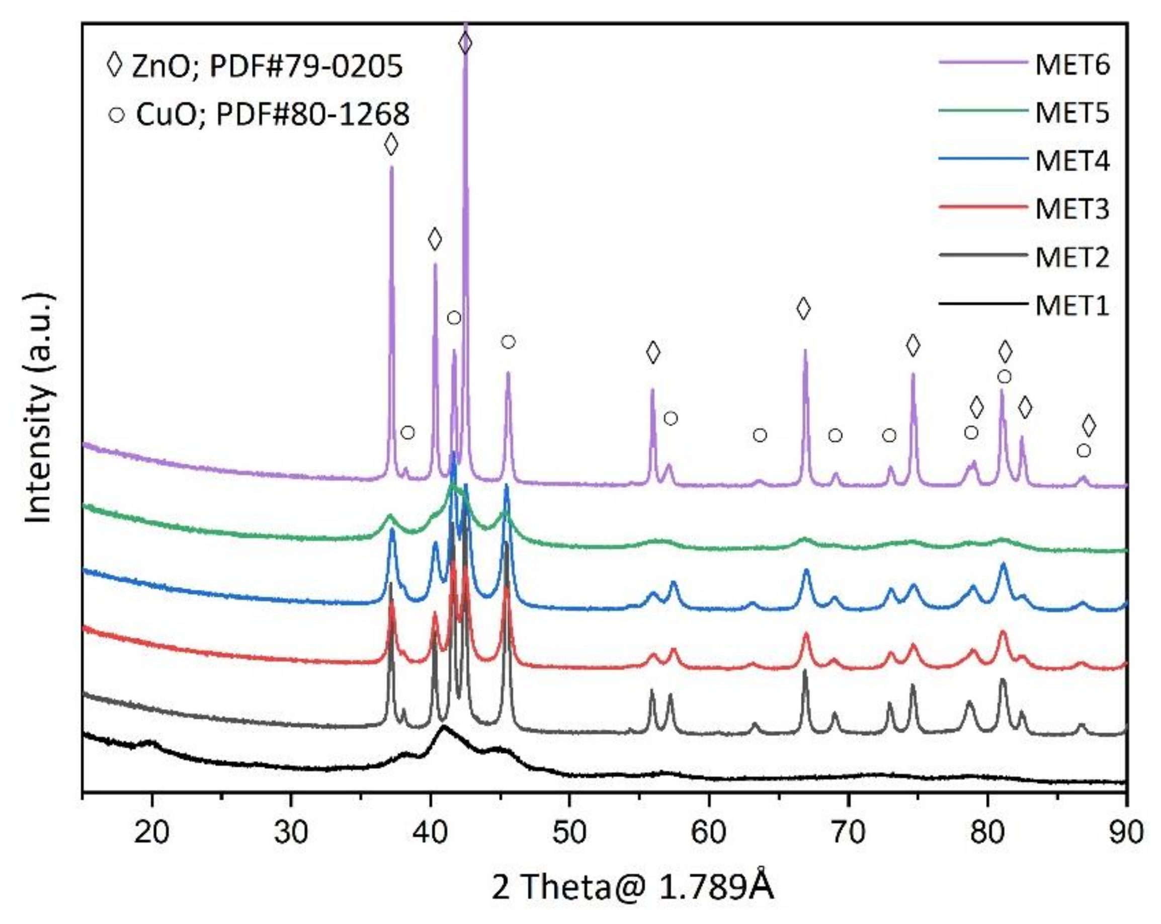
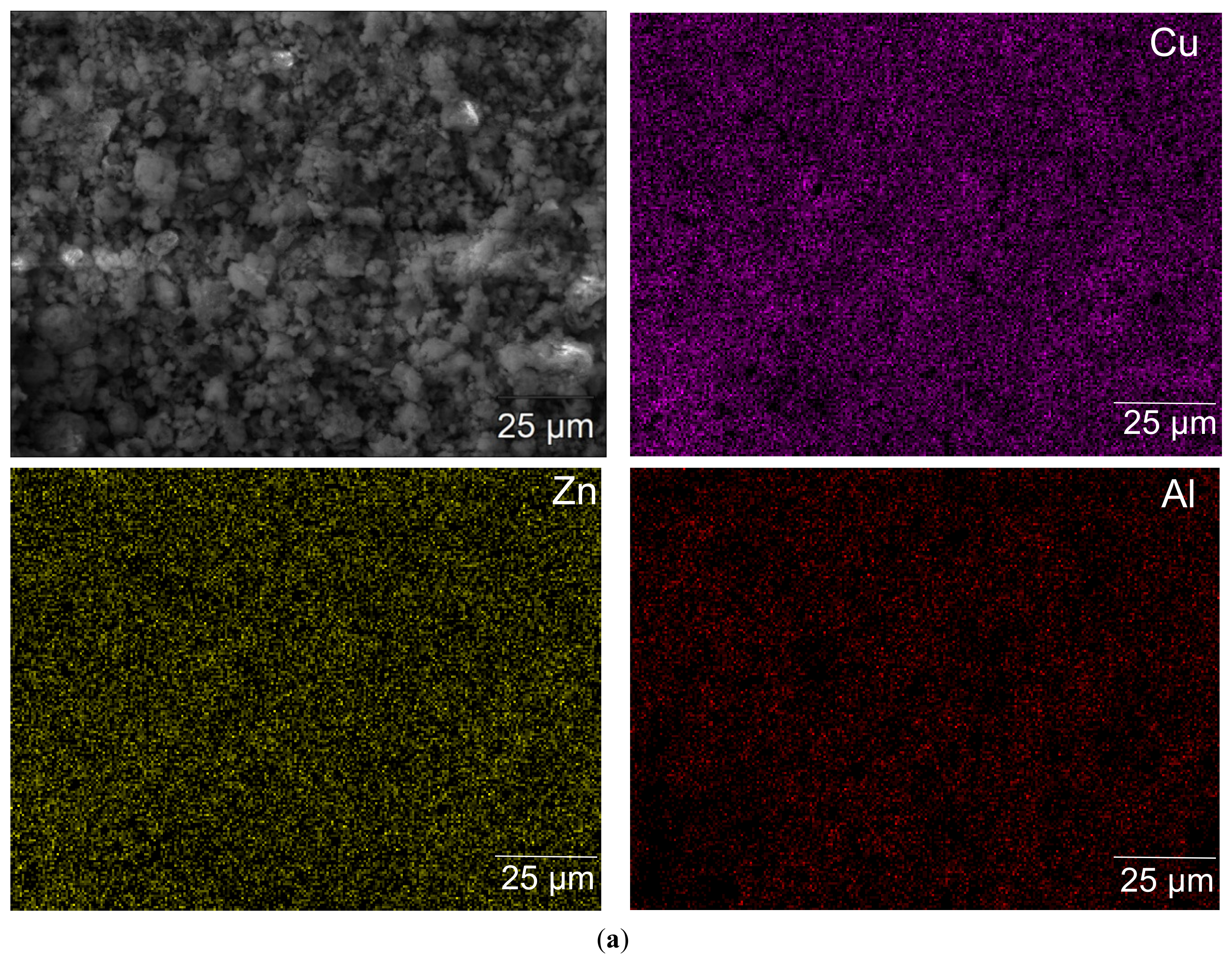
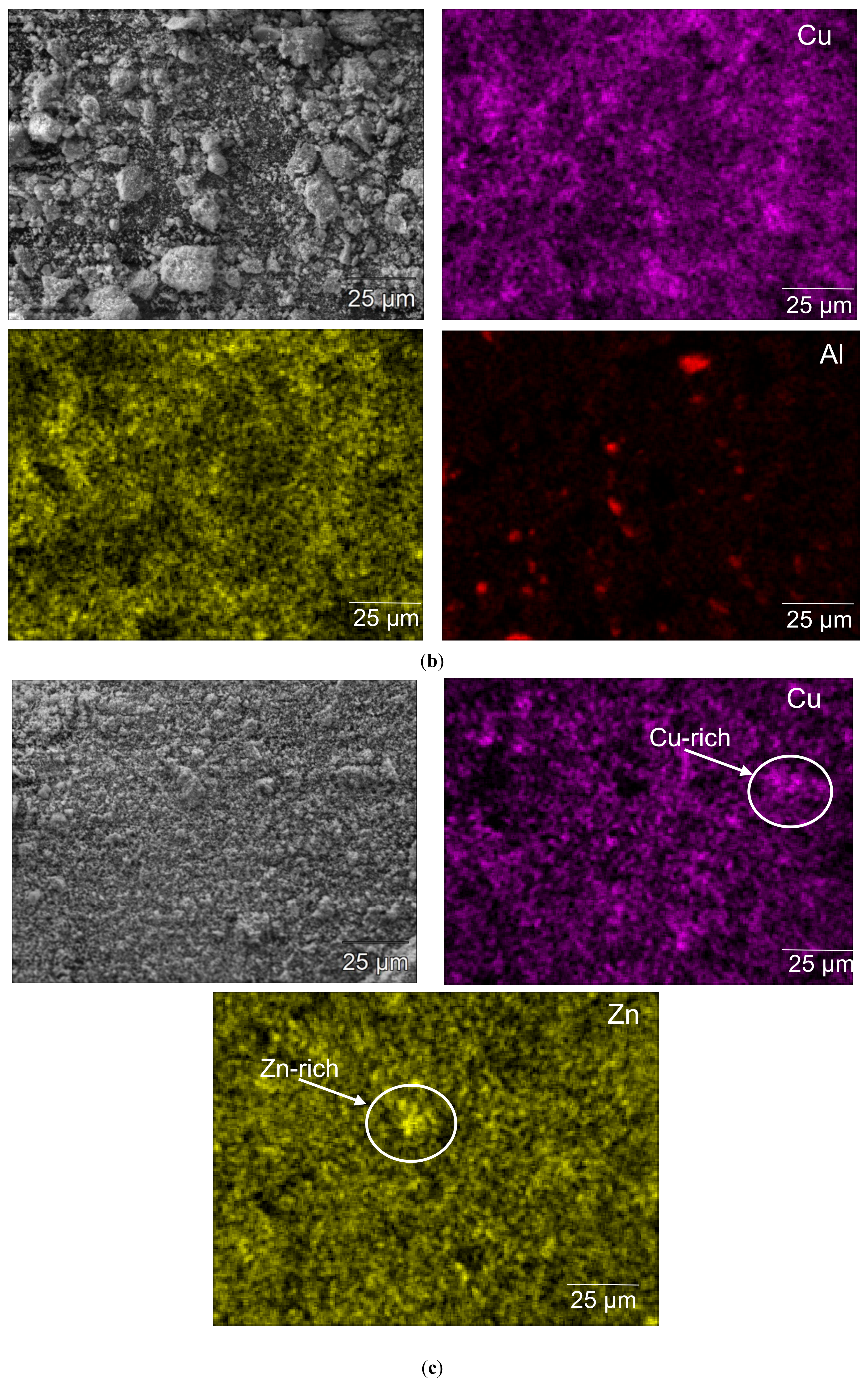
3.1. Catalyst Characterizations

The BET results show that except for MET6 and MET7, the nitrogen adsorption-desorption isotherms for all other catalysts (as typically observed for MET2), are type IV with the hysteresis loop, which usually is an indication for a mesoporous structure with slit-shaped pores. Detailed BET results of these samples have not been reported here for the sake of shortening the paper, but they have been observed to represent relatively flat isotherms, which is an indication for the porosity of the samples caused by a dense agglomeration of metal oxides. On the other side, type II isotherms were identified for the samples MET6 and MET7, which generally is an indication for their macro porous characteristic. The specific surface areas and the pore size distributions of all samples, which have been calculated by (Barrett–Joyner–Halenda) BJH method, are shown in Table 1. These should be considered while analyzing the performance of the catalytic samples.
Figure 1 shows the XRD pattern for the catalyst-samples MET 1–6.
All the peaks indicated in this figure are related to CuO and ZnO. All the samples have very clear CuO (111) reflection based on which the size of copper oxide crystallites could be calculated. The broadened peaks of MET1 and MET5 indicate a rather small crystallite size in the nanometer range. This is also indicated through their relatively larger specific surface area as reported in Table 1. The relation between the catalyst selectivity and the size of the Cu particles is known and has been fully explained elsewhere [22]. More details on the implementation of different methods to calculate the copper oxide particle sizes and their impacts on the performance of the catalysts have been also already discussed extensively and can be found elsewhere [21,23]. However, it should be mentioned that by using the XRD data for analyzing the surface characteristics of the samples, usually only the large particle-sizes are observed, while the impacts of the small particle sizes needs to be also taken into analysis. The presence of such small particles has already been shown and proven via the previously reported characterization results of these catalysts.
SEM-EDX mapping of the MET1, MET2 and MET6 are presented in Figure 2, through which also the distribution of the active components over the surface of the catalysts can be observed.
The EDX pictures for MET1 and MET2 show a homogenous distribution of copper over the entire surface of these catalyst samples established by the implemented synthesis methods. On the contrary, the dispersion of copper over the surface of MET6 and MET7 is not homogenous. It is known that the better distribution of the metal species over the catalyst surface results in relatively lower local metal loading and increases the portion of the strong basic sites, which positively contribute to selective methanol formation [27,28]. Having generally reviewed all these and without going into details, the main focus in this step is to explain the observed different selectivity of the investigated catalysts. For instance as will be discussed in next section, the observed relatively higher methanol selectivity of MET1 and MET2 (synthesized via co-precipitation method) can be mainly attributed to the proven relatively homogenous distribution of the Cu and Zn species over the surface of these catalysts.

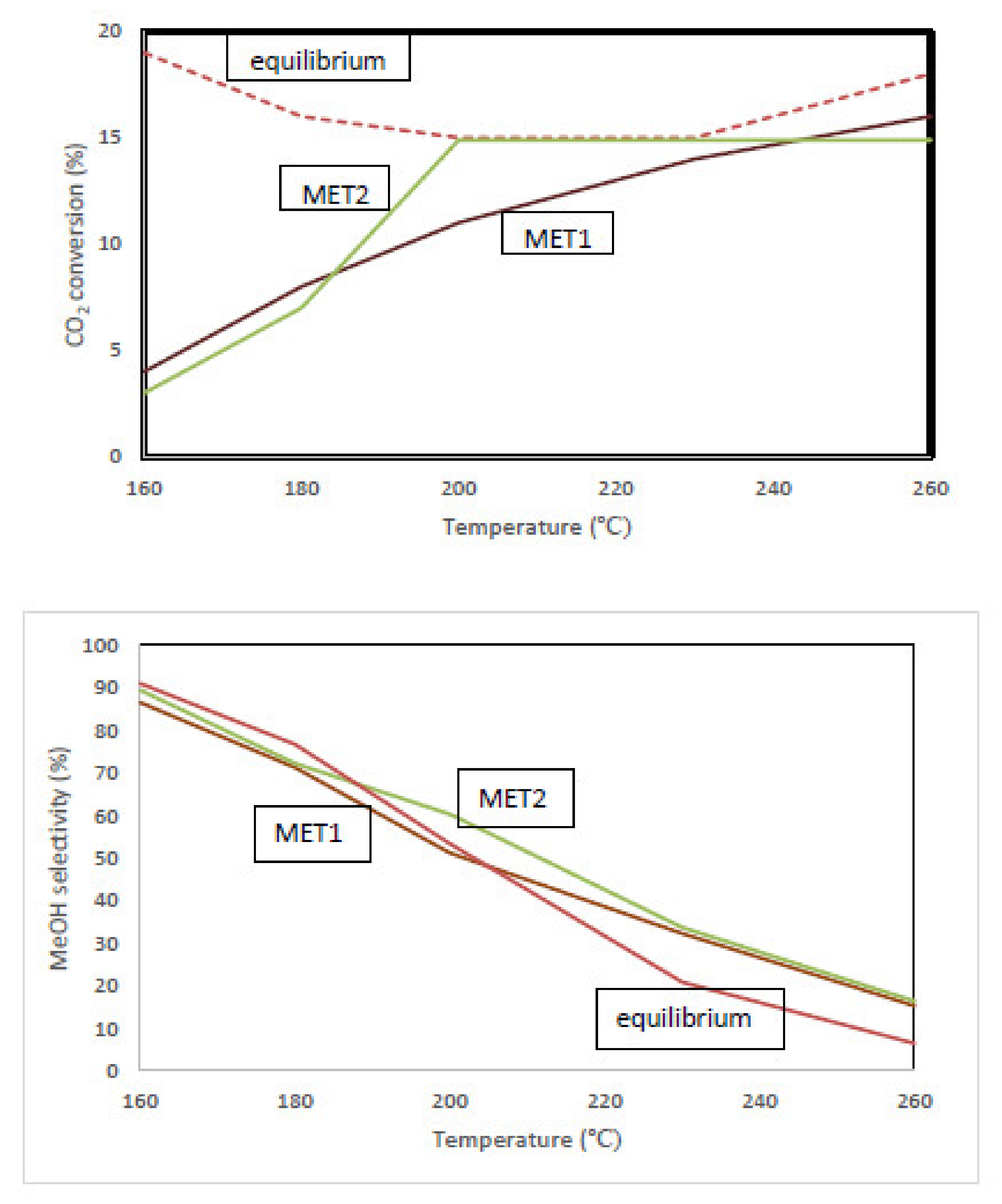
3.2. Catalytic Performance

Testing the catalytic performance of the samples in this research was designed to be conducted in four steps in order to step-by-step screen the catalysts’ activity, selectivity, and stability with the view on their possible industrial-scale operation:
Step one: comparative performance analysis of all selected catalysts under the operating range recommended in the original references.
Step two: comparative sensitivity analysis of the short-listed catalysts under the preferred range of operating conditions (GHSV and temperature) determined after the first step (step one).
Step three: searching for the best catalytic performance through a well-designed full-factorial experimentation, represented in Table 2 and Table 3, to analyze the impacts of the operating temperature and H2/CO2 ratios on the performance of the final selected catalysts. Results are evaluated also in reference to the equilibrium-based calculated achievable performance of the CO2-hydrogenation under these conditions.
Step four: stability tests under (a) long-term hydrogenation reaction, (b) sequence of reducing-reaction atmospheres and (c) before and after exposing the catalysts to oxygen.
In the first step (step one) of the experimentation, all identified Cu/ZnO catalysts (MET1–MET7) were tested close to the range of operating conditions recommended for each one in the original references, under which their best observed performance have been observed. In this manner and in order to compare the performance of these catalysts, the GHSV was set to 684 (h−1) while they were tested in operating temperature range of 200–260 °C at H2/CO2 ratios of 3, 6 and 9. All experiments were repeated at least three times and the standard deviations were calculated to be below 5%.
For all tested catalysts, methanol and CO were observed to be the main products and only a trace of CH4 was detected via the GC. The observed results of this screening step are reported in Table 2.
Most of the reported results in Table 2 follow the expected trends as also previously recorded for these catalysts [16,17], confirming that an increase in the operating temperature causes an increase in the CO2 conversion and CO selectivity and thereby a decrease on the methanol selectivity. This could be explained based on the impact of temperature on the rates of competing CO2 hydrogenation reaction to methanol and the reverse water gas shift (RWGS) reaction. These reactions are represented as followings:
CO 2   +   3 H 2     CH 3 OH   +   H 2 O     Δ H 298   =   49.5   kJ . mol 1
CO 2   +   H 2     CO   +   H 2 O     Δ H 298   =   41.2   kJ . mol 1
Increasing the temperature is more favorable for the RWGS reaction due to its endothermic thermal characteristic. Therefore, for the next step of the experimentation, narrower lower range of temperature (200–230 °C) was applied.
Having considered the stoichiometry of the reactants in these reactions implies that CO2 hydrogenation to methanol is a more preferred path in case of using excess H2. In fact, increasing the hydrogen content in the feed significantly increases the CO2 conversion and methanol yield and decreases the CO selectivity. This has been explained also elsewhere via quantitative analyzing of the relative impact of the partial pressure of CO2 and hydrogen on the formation rate of methanol [16]. Interaction of the adsorbed species with the Cu and the oxide components, and in general the contribution of the Cu particle size and Cu surface area on the activity and selectivity of these catalysts have been also discussed there [16] as well as in many other references [22], suggesting that for the given Cu content and oxide supports, the smaller size Cu particles cause higher Cu surface area and thus a higher yield towards methanol. This was observed for the catalyst samples MET3, MET4 and MET5.
After analyzing the experimental results of the first step, in order to highlight the main practical theme of this research, the catalysts showing a methanol yield of higher than 4% using H2/CO2 = 3 and temperature of 200 °C were selected to be further investigated in the next steps. It was found that MET6 and MET7 catalysts synthesized by the impregnation method were not active enough, as their conversion was relatively low. The relatively lower Cu content (only 15%), heterogeneous dispersion of the Cu components on the surface of these catalysts, confirmed via several SEM-EDX images of different parts of the catalysts samples, and their relatively less mesoporous structure are believed to be the main reasons for relatively low activity–selectivity of these catalysts. Therefore these catalysts (MET6 and MET7) were not further investigated and the analysis continued with the remaining catalysts.
Having fixed the operating pressure and temperature as well as the size of catalytic bed, less feed and therefore lower GHSV could be applied in order to improve the conversion of carbon dioxide in the next step of the experimentation. Therefore, comparative performance tests of the remaining catalysts (MET1–MET5) under the lowest range of feed flow were conducted. The targeted feed flow was therefore determined, based on the targeted feed composition and by considering the lowest range of flow in the mass flow controllers, which ultimately led to establishing the actual GHSV of 200 h−1 inside the catalytic bed. The results of the performed comparative tests under this low GHSV (200 h−1), enabled analyzing the impacts of varying temperature and H2/CO2 ratios on the CO2 conversion and methanol selectivity of the investigated catalysts under such intense reaction environment as reported in Table 3.
Mainly due to the longer contact time established in this set of experiments, the CO2 conversion was increased. It should be taken into consideration however, that decreasing the gas hourly space velocity may increase the intensity of reaction, resulting in higher reaction temperature along the catalytic bed, and also because of that it may affect the CO2 conversion and reaction performance in general. Having considered such interactive effects, reducing the GHSV does not always favor methanol formation and the RWGS reaction can be intensified in this way and thereby more CO can be produced. This indicates that not only the activity, but also the selectivity of the reaction system will be affected by varying the GHSV or the contact time. Therefore, beside considering the involved catalytic kinetic and mechanism aspects, thermal effects of the reactor design should be also taken into analysis for describing the performance of this reaction system.
Having analyzed the performance of all catalysts in these series of experiments, MET1 and MET2 catalysts showed the highest methanol yield under H2/CO2 ratio of 3, which represents the lowest stoichiometric ratio of expensive-to-inexpensive educts and therefore the most practically relevant conditions for this catalytic reaction system in its industrial-scale operating perspective. Among the synthesized catalysts, these two catalysts also have shown relatively the most homogenous distribution of the surface–active components, as earlier discussed. In fact, the best recorded methanol yield for low-pressure CO2-hydrogenation has been previously reported for catalyst MET2 [17]. As expected, the research-benchmark MET1 catalyst has also performed very well. Therefore, the observed results for these catalysts in current research reconfirm their promising potential.

3.3. Equilibrium-Limited Achievable Performance

The finally selected catalysts MET1 and MET2 were tested in wide range of operating temperatures (160–260 °C) to track the impact of temperature on the observed methanol selectivity and CO2 conversion, while comparing these values with their ultimate achievable values calculated based on the thermodynamic equilibrium limitations and the Gibbs free energy minimization of products’ formation. These values were calculated using Aspen Plus simulator 8.8 and SR-Polar equation of state for a given set of reaction conditions (T, P, H2/CO2 ratio). In such calculations, all involved reactions including the equilibrium CO2 and CO hydrogenations and water gas shift reaction have been taken into consideration.
As shown in Figure 3, by tracking the trends showing the effect of operating temperature on the CO2-conversion and methanol selectivity, it can be observed that for the GHSV of 200 h−1, a pressure of 9 bar and H2/CO2 ratio 3, the highest methanol yield can be secured by operating at temperature of 200 °C.
Although achieving higher methanol selectivity and yield is theoretically predicted at lower temperatures from the sole equilibrium point of view, the temperatures lower than 200 °C cannot activate the catalyst enough to secure a significant CO2-conversion and thereby high methanol yield. The reaction temperatures of higher than 200 °C, thermodynamically favor unselective conversion. Therefore, at higher temperatures, the results show a decrease in methanol yield mainly because of the poor selectivity. This is the case for both the investigated catalysts, MET1 and MET2.
Thermal performance of the reactor and the temperature distribution along the catalytic bed should be also taken into consideration while interpreting these observed data, especially the ones which are very close to the equilibrium performance. In this manner, the actual equilibrium data correspond to the actual local reaction temperature which might be higher or lower than the ones demonstrated in Figure 3. This again indicates that the observed performances are not solely reflecting the involved catalytic kinetic and mechanisms but also they reflect the impacts of the thermal characteristic of the reactor system as an important extrinsic parameter. Thermal characteristics of reactor operation will affect the reactions selectivity specially the contribution of RWGS reaction and the achievable CO2-conversion and methanol yield as they are a function of actual local reaction temperature along the reactor.

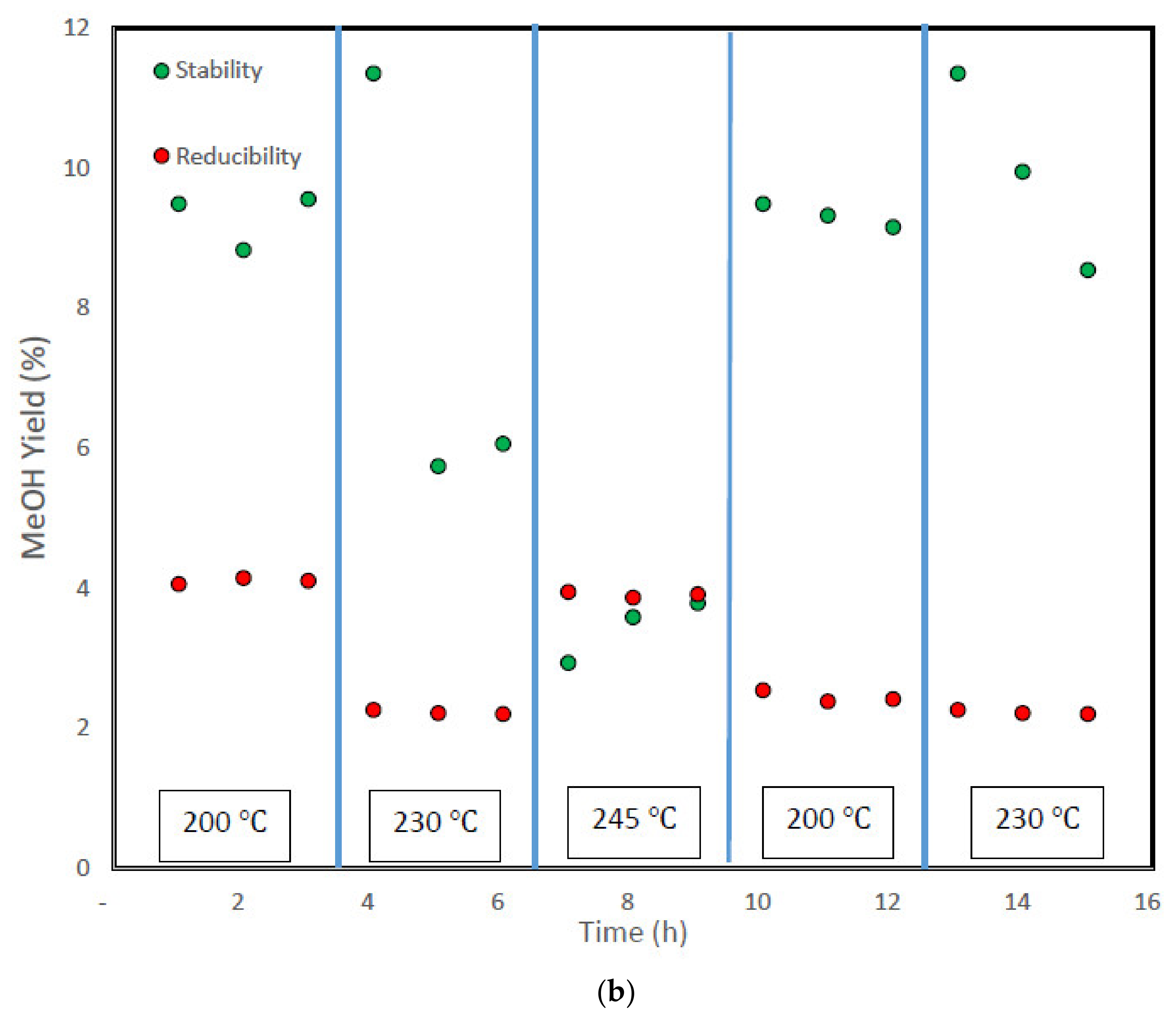
3.4. Stability Test and Analysis

In the last step of the experimentation, the stability of the selected catalysts was tested through two different approaches:
Durability: the final selected catalysts (MET1 and MET2) were tested each for 150 h and no significant reduction of activity was observed. This has been the case even when the reaction atmosphere and temperature have been repeatedly switched between the hydrogenation reaction, the inert and the reducing atmospheres. Based on these observations it can be concluded that no significant deactivation along the time and/or due to the temperature changes has been observed. Similar findings have been also reported by Karelovic and Ruiza [22].
Reducibility: in order to test the reducibility of the catalysts, the performance of the freshly reduced catalysts and the performance of the reduced catalysts after being exposed to oxygen were tested and compared. In this manner, first the fresh catalysts were reduced and tested for the designed reference experiments. Then, 100 mL/min air was introduced to the catalytic bed for 1 h. The catalysts were then reduced with the same recipe and tested under the same set of designed reference experiments.
As it can be seen in Figure 4, there is a significant difference between the performances of the freshly reduced catalysts in normal operation and the reduced catalysts after being exposed to oxygen even for a short time. In order to explain this, it should be highlighted that the copper content of the calcined catalyst in its body and also on its surface are in CuO (oxide) form in a dynamic interaction with the ZnO and Al2O3 components [28]. Reducing the catalyst converts the copper oxide to copper. Then, under CO2-hydrogenation reaction, copper is converted back to its original CuO status. Therefore, the available copper on the catalyst surface and its interaction with other oxide species does not change because of the temperature shock or after several cycles of hydrogenation-reduction reactions. This is the reason why no significant deactivation during the long-term (150 h) experimentation has been observed.
After introducing the oxygen to the catalytic bed, however, the copper content over the catalyst surface is transformed to a different copper-zinc-alumina state, but this time there is no interaction between some of these CuO components and the other separate oxides, namely ZnO and Al2O3. Therefore, such formed material state cannot be easily reduced to its original form and a significant deactivation was observed in the corresponding experiments.
Figure 4 shows the observed stability and reducibility of the catalysts MET1 and MET2. These experiments have been conducted for H2/CO2 =3, P = 9 bar g and T = 200 °C. The catalyst activity-selectivity mechanism discussed above and elsewhere, highlight the crucial impact of interaction of hydrogen and carbon dioxide with reducible CuO and other oxide species. Fine distribution of the copper over the catalyst body is an important factor in this regard.

4. Material and Methods

4.1. Selected Catalysts and Synthesis Methods

The recipes and the chemicals used for synthesizing these selected types of Cu/ZnO catalysts are reported in this section and the list of utilized chemicals is provided in Table 4.
The details of the implemented synthesis approaches including all required information allowing to reproduce these catalysts, are reported in this section and can be also found in more details in the provided original references in each case.

4.1.1. Co-Precipitation Method for Preparation of Cu/ZnO/Al2O3 Catalyst

This type of Cu/ZnO catalyst was prepared by the coprecipitation method described by Behrens et al. [26]. Molar aqueous solutions of Cu(NO3)2·3H2O, Zn(NO3)2·6H2O and Al(NO3)3 were prepared. They were then mixed together to result in an overall metal composition of 68:29:3 (Cu:Zn:Al). An aqueous solution of one molar sodium carbonate was added to the mixture under stirring at 65 °C to reach the pH of 6.5. In this manner, the resulted 2000 cc metal nitrate solution was acidified with 15 cc concentrated HNO3 and the carbonate solution as a basic precipitating agent, dosed in 1200 cc deionized water. The precipitation was established at the same temperature for 30 min and the color of the mixture was changed from green to bluish green. The precipitate was centrifuged and washed with deionized water and dried overnight at 110 °C and then calcined at 330 °C for 4 h with the heating ramp of 2 °C per minute. Here, the resulted catalyst is referred to as MET1.

4.1.2. Hydrolysis Method for Preparation of Cu/ZnO/Al2O3 Catalyst

The selected recipe for preparing Cu/ZnO/Al2O3 catalyst using hydrolysis method has been reported by Xu et al. [17]. Cu(OH)2-Zn(OH)2 precipitate was prepared by adding one molar Na2CO3 to the premixed solution of Cu(NO3)2 and Zn(NO3)2, prepared by mixing a liter of one molar solution of each of them, to reach the pH of 8 under stirring and ambient temperature. The precipitate was then washed with deionized water. In parallel, a proportional amount of one molar solution of Na2CO3 was added to the prepared 254 cc one molar solution of Al(NO3)3 to reach the pH of 8 under stirring and ambient temperature. The precipitate Al(OH)3 (gel form) was also washed with deionized water. Precipitated Cu(OH)2-Zn(OH)2 and Al(OH)3 were then mixed in a mortar and stirred to get a homogenous mixture to obtain the hydroxide mixture containing Cu(OH)2, Zn(OH)2 and Al(OH)3 in a molar ratio of 47, 47 and 6, respectively. The mixture was then dried at 120 °C for 12 h. The dried product was calcined at 350 °C for 3 h followed by further calcination at 500 °C for 1 h with the heating ramp of 3 °C per minute. Here, the prepared catalyst is referred to as MET2.

4.1.3. Coprecipitation Method for Preparation of Cu/ZnO/Al2O3 Catalyst

The third type of Cu/ZnO/Al2O3 catalyst was prepared by the coprecipitation method described by Jingfa et al. [21]. Aqueous solutions of Cu(NO3)2·3H2O, Zn(NO3)2·6H2O and Al(NO3)3 each in 0.1 concentration were prepared and mixed together to reach the metal composition of 45Cu:45Zn:10Al in the precipitate phase. An aqueous solution of 1 molar oxalic acid was added rapidly to the prepared mixed solution under stirring and ambient temperature. In this manner, a mixture solution of the Cu(NO3)2·3H2O, Zn(NO3)2·6H2O, Al(NO3)3 and oxalic acid was composed of 45/45/10/120 volume units of each single solution, respectively. The mixture was aged for 30 min and the precipitate was centrifuged and washed with deionized water. It was then dried overnight at 110 °C and calcined step-wise at 150, 200, 250 and 300 °C each for 1 h and finally at 360 °C for 4 h with the heating rate of 2.5 °C per minute. In this paper, this resulted catalyst is referred to as MET3.

4.1.4. Gel-Coprecipitation Method for Preparation of Cu/ZnO/Al2O3 Catalyst

This catalyst was prepared by the gel-coprecipitation method, which is very similar to the typical coprecipitation method applied for synthesizing MET3. For gel-coprecipitation, however, ethanol was used as the solvent in all corresponding solutions [21]. Reduction of the volume of the resulted dried particles indicates its gel characteristic. Here in this paper, the resulted catalyst is referred to as MET4.

4.1.5. Conventional Carbonate Coprecipitation Method for Preparation of Cu/ZnO/Al2O3 Catalyst

This catalyst was prepared by the conventional carbonate coprecipitation method using the same precursors and solutions used for synthesizing MET3 and MET4 to reach the same precipitate phase composition [21]. For carbonate coprecipitation however, 100 CC of 0.1 mol sodium carbonate solution was added and the pH was measured during this synthesis to be kept constant at 6.5–7. Here in this paper, the prepared catalyst is referred to as MET5.

4.1.6. Citrate and Impregnation Method for Preparation of Cu/ZnO Catalyst

As the first step of synthesizing this catalyst, ZnO particles were prepared by citrate method. In order to do so, the proper amount of 1 molar citric acid solution was added dropwise to a 0.5 mol solution of Zn(NO3)2·6H2O while it was moderately stirring [23]. The solution was left being stirred at room temperature overnight, and after that it was transferred to a rotary evaporator. The evaporator was working under 40 °C and a partially vacuum atmosphere. The solution was transformed to a more viscous fluid which was further dried in a vacuum oven at 80 °C. These conditions caused a significant increase in the volume of the solidified mixture before it was dried for more than 48 h. The sample was then calcined at 350 °C with the heating rate of 2.5 °C per minute.
In order to prepare the solution for impregnation, a proportional amount of Cu(NO3)2·3H2O was dissolved in deionized water and the already synthesized ZnO was added to it while it was stirring at room temperature to establish 15 wt % Cu in the final catalyst. The mixture was kept being stirred for 5 h and the water was removed from it using a rotary evaporator under vacuum and temperature of 40 °C. The dried resulted particles were calcined at 350 °C for 4 h with the heating rate of 2.5 °C per minute to achieve the final powder catalyst here in this paper referred to as MET6.
The same procedure was used to impregnate the purchased powder of Yttrium aluminium garnet (YAG, Y3Al5O12) and the prepared catalyst in this manner is referred to as MET7.

4.2. Catalyst Characterization

Reviewing the physical–chemical properties and the performance of the wide range of the investigated catalysts (Cu-ZnO/Al2O3) in this research enables one to highlight the striking features of the desired catalysts for CO2 hydrogenation to methanol. For instance, tracking the phase compositions and the dispersion of Cu can provide valuable information in this regard. Based on the performed characterizations, Cu+ and ZnO in the solid solution of the investigated catalyst MET2 have been suggested to be the active centers under the investigated reaction conditions [17]. However, it should be emphasized that in this research it was not intended to find any structure–activity relationship or draw any fundamental conclusion with regard to the understanding of the catalytic mechanism or behavioural pattern of the studied systems, as it was out of the scope of the current paper and would have required extra characterization and tests and even studying other types of distinguished catalysts synthesized by other types of support or active components [29,30,31].
It should be mentioned that most of the investigated catalysts in this research have been also characterized in previous studies. For instance, general characterization techniques such as XRD, TEM and thermal analysis (TG/DTG) have been previously [21] applied for the most of the selected catalysts in this research. In order to conduct a comparative study, the characteristics of the selected catalyst samples, using XRD, BET and SEM characterizations, have been analysed and reported and conceptually compared with each other in the current research. These results can be also directly compared with the reported characteristics of similar catalytic systems in literature. This can be generalized for the other measured/reported characteristics, except for the few parameters such as pore dimeters of the MET3 and MET4 which have been measured to be 50% smaller than their original reported values of 10–14 nm [21]. The results of these basic characterization techniques (i.e., XRD, BET, SEM) can be also used for studying the impacts of the structure and the morphology of the catalysts as well as their involved crystalline phases on their catalytic performances. Moreover, the results of the physical–chemical characterization methods which are sensitive enough to identify the characteristics of the external surface, for instance for detecting the copper species before and after the reaction using XPS analysis, and the ones determining the reactivity of the solids (chemisorption, IR) for some of these catalysts are available elsewhere [17,23].
Calcined catalysts samples were characterized by applying X-ray powder diffraction (XRD) analysis technique in the 10 ° 2 θ 90 °   range on a Brucker D8 advance diffractometer via Co-Ko radiation (using 1.541 Å, 40 kV, 35 mA, Berlin, Germany) at a scanning rate of 2K/min to identify the crystalline phases. The BET surface area and the pore size distribution of all catalysts were calculated based on the N2 adsorption-desorption measurements at −196 °C. The proper amount of catalyst samples (corresponding to 10–100 m2 surface) were degassed under vacuum atmosphere. During the pre-treatment period, each sample was heated under a step-wise rising temperature profile starting with 80 °C, followed by being heated under 120 and 180 °C each for one hour and finally at 220 °C for 4 more hours with the heating rate of 3 °C per minute in order to clean the surface and pores of the sample. After degassing the BELprep-VACII preparation equipment (Berlin, Germany), the sample was weighed again to quantify the dried mass of the materials. The cell was then placed in the BELSORP-mini II measuring equipment (Berlin, Germany) and then into a Dewar vessel of liquid nitrogen. N2 was stepwise introduced to the samples until reaching the ambient pressure and then was step-wise vacuumed in order to measure the N2 adsorption and desorption behaviour of the samples.
In order to study the surface morphology and the homogeneity of the samples, a Zeiss Gemini Leo 1530 Field Emission Scanning Electron Microscope (FESEM, Berlin, Germany) was used, which is equipped with energy-dispersive X-ray spectroscopy (EDX).

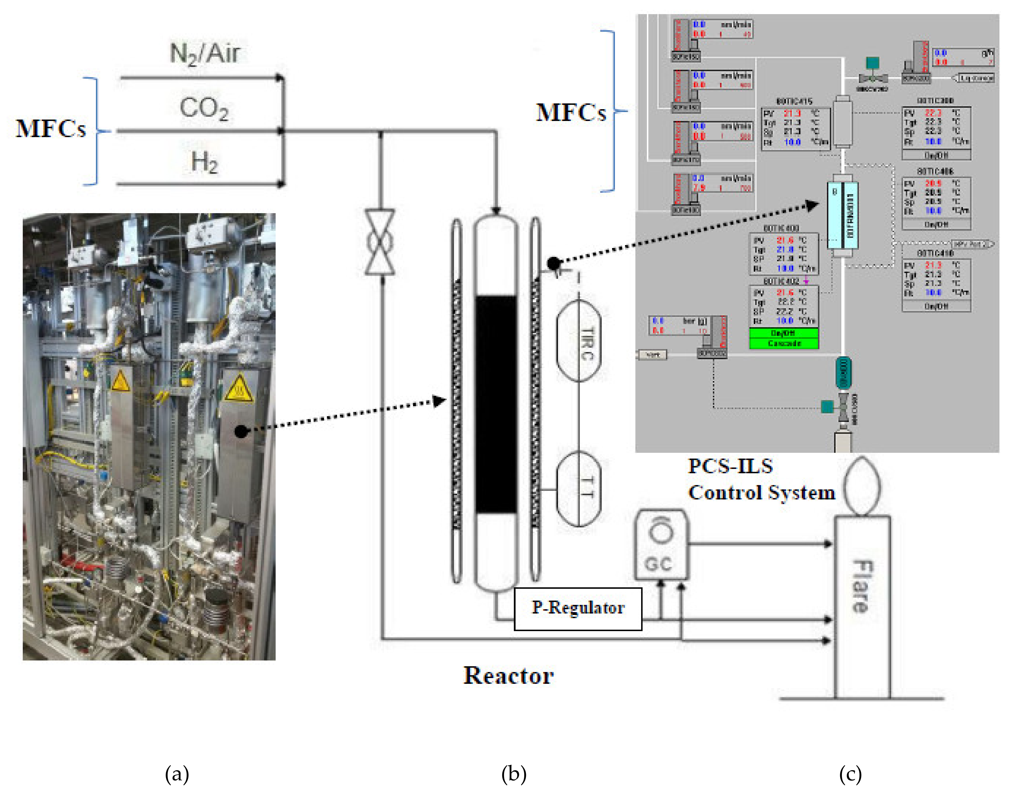
5. Experimentation for Catalyst Testing

The specification of the experimental setup and the design of experiments as well as the procedure of testing the catalysts are reported in this section.

Experimental Setup

The schematic of the experimental setup utilized for testing the catalyst is depicted in Figure 5.
A picture of the setup and the visualization interface of the control system can also be seen there.
In this setup, the operating temperature, pressure and feed composition are respectively controlled via an electrical tube furnace, back pressure regulator and several mass flow controllers. The set-points and the measured values of the feed flow rates, operating pressures and the applied temperature of the three electrical elements/zones in the furnace are set and monitored online through the user-interface PCS-ILS control system as shown in Figure 5.
The temperature could be set either as the temperature of the furnace (local-mode) or the temperature inside the catalytic bed (cascade-mode), which was the case for most of the experiments in this research. The thermocouple located inside the tube was in touch with the top of the catalytic bed inside the vertical reactor, where feed gas enters from the top. The volumetric feed flow rates of nitrogen, carbon dioxide and hydrogen were controlled using Bronkhorst F-series mass flow controllers (MFC) with a 0.8% precision range around the measured values. The operating pressure inside the reactors was controlled using an electronic back-pressure controller.
For each experiment, a 20 cm long catalytic bed, made of 200–400 micron sieved powder of each catalyst, was located inside a stainless steel fixed-bed reactor with an inner diameter of 8 mm. The bed was positioned in the height of the middle electrical heating element/zone. In order to fix the location of the catalytic bed, the bottom part of the reactor was filled with inert packing and quartz wool. For calculating the required amount of inert packing and the catalyst for each run and in order to ensure proper filling the reactor, the locations of the heating zones as well as the values of inner diameter of the reactor and the density of catalysts were taken into calculation.
After placing the reactor inside the furnace and fixing the connections, the feed-mixture composed of the desired portions of nitrogen (or air solely used for specific type of stability tests), hydrogen and CO2 were tuned for establishing the targeted reducing, purging and reaction atmospheres. The required overall gas feed flow rate to be introduced to the reactor for representing the targeted actual gas hourly space velocity (GHSV) inside the catalytic bed is calculated using Equation (1):
GHSV = 60 × Q × 273.15 + T cb V cb × P × 273.15 + T a
Here, Vcb is the volume of the catalytic bed, P is the pressure in bar, Tcb is the temperature inside the catalytic bed and Q is the set feed flow rate by the mass flow controllers, calibrated for standard reference pressure and temperature (STP: P = 1 bar and Ta = 0 °C).
In the reduction period, hydrogen flow of 80 mL/min was used to reduce the catalyst under ambient pressure and temperature of 300 °C for six hours. The reactor was then cooled down to the targeted reaction temperature for each experiment using proper flow rate of nitrogen while pressure was set to 10 bar. The wall-temperature of the reactors’ outlet pipe-lines to the GC were kept at 170 °C to prevent condensation, which affect the mass balance and can cause a fluctuation of the operating pressure.
After reaching around the desired temperature range in the catalytic bed, the gas feed was introduced to the reactor and a period of approximately 30 min was considered as the stabilization time. Then, the gas stream was introduced to the gas chromatograph (GC) analyzer. The gases were analyzed by a Schimadzu 2014 ATF GC (Berlin, Germany) equipped with a methanizer, a thermal conductivity detector (TCD), a flame ionization detector (FID) and two packed columns (HayeSep Q and Molecular sieve 13X) used for analyzing H2, N2, CO2, CO, CH4 and methanol in all gas streams. Argon was used as the carrier gas for both columns.
The setup is equipped with a multi-position valve to send the desired stream to the gas chromatograph. This was especially instrumental in conducting the experiments while two OCM and methanol reactors ran consecutively as coupled-reactors configurations, reported in part II of this paper.
In order to calculate the CO2 conversion, products’ selectivity and yield, a small amount of nitrogen was fed as an inert reference species, which does not participate in any reaction and therefore the same amount of nitrogen will appear in the product stream. Knowing its molar inlet flow (xin × Qin) and by measuring the outlet nitrogen mole fraction (xout) with GC, the molar flow rate of the total product stream can be calculated using the following equation.
Q   out = x N 2 in ×   Q   in   x N 2 out
The value of the calculated outlet flow has been rechecked time to time using a standard calibrated flowmeter under the outlet temperature and pressure. The molar flow rate of each component in the product steam is then calculated by multiplying the above-calculated total outlet flow rate with the mole fraction of each component measured by the GC. Based on these data, the CO2 conversion (X), methanol selectivity and yield (S and Y) could be calculated as following:
Conversion of carbon dioxide (X) is calculated using Equation (3).
X   % = F CO 2 in   F CO 2 out   F CO 2 in
Selectivity towards methanol (S) is calculated using Equation (4).
S   % = F CH 3 OH out F CO 2 in   F CO 2 out
Methanol yield (Y) is calculated using Equation (5).
Y   % = F CH 3 OH out   F CO 2 in  
Having considered the precision of the measurements and the control devices, the observed selectivity, conversion and yield in average have ± 10% margin of error in reference to their reported values in this manuscript. This means that for instance, the actual value of CH3OH-Yield lies in the range of 0.9 × CH3OH-Yieldreported < CH3OH-Yieldactual < 1.1 × CH3OH-Yieldreported.

6. Conclusions

A comprehensive review analysis on the low-pressure performances of the selected CO2-hydrogenation catalysts has been provided in this paper. The performed experimentation and testing of the selected CO2-hydrogenation catalysts showed that some receipts of Cu/ZnO/Al2O3 catalysts exhibit a stable active catalytic performance promising for industrial-scale operation. It was observed that the coprecipitation catalyst synthesis approach, which is known for its potential of establishing a homogenous distribution of active components over the whole catalytic body, provided the highest methanol selectivity and yield. All tested catalysts have shown their best performance, in term of methanol yield, for the highest applied H2/CO2 ratio and lowest GHSV. A methanol yield of 21% using the H2/CO2 ratio of 9 and the temperature of 200 °C under 10 bar pressure was the best catalytic performance achieved.
After testing the stability of the selected catalysts under long-term operation as well as the reaction-reducing shifting-atmospheres and even after introducing oxygen to the catalyst surface followed by reducing-reaction tests, it was found that exposing the catalyst with oxygen can significantly affect the stability of some of the catalysts. Moreover, it was found that the performance of some of the selected catalytic systems, especially in the average range of temperatures, can come very close to the ultimate achievable performance predicted by considering the thermodynamic-equilibrium limitations. Thermal characteristics of the reactor operation were shown to also be important in determining the ultimate achievable yield of methanol in this system.
The experimental analysis conducted in this research (part I) will support the novel efficient implementation strategy for industrial-scale utilization of the CO2-hydrogenation catalytic system (represented by the selected catalyst MET2) as an add-on process to be integrated with the case-study process oxidative coupling of methane (OCM). This will be analyzed in part II of this manuscript.

Supplementary Materials

The following are available online at https://www.mdpi.com/2073-4344/10/5/505/s1, Table S1: A selective overview of the reported performances for catalytic hydrogenation of CO2 to methanol (Specially the studies performed at low-medium pressure).

Author Contributions

Conceptualization, H.R.G. and S.M.J.; Formal analysis, L.T. and O.G.; Investigation, H.R.G., M.K., M.A. and O.G.; Methodology, H.R.G., M.K. and S.M.J.; Resources, R.S., G.W. and J.-U.R.; Software, M.A.; Supervision, H.R.G., O.G., S.M.J., L.T., R.S., G.W. and J.-U.R.; Visualization, O.G.; Writing—original draft, H.R.G. and M.A.; Writing—review & editing, H.R.G., O.G., G.W. and J.-U.R. All authors have read and agreed to the published version of the manuscript.

Funding

This research received no external funding.

Acknowledgments

Catalyst sample preparation by Elias Freie (Department of Inorganic Chemistry, Fritz Haber Institute of the Max Planck Society, Berlin, Germany) is sincerely acknowledged. The authors acknowledge the financial support from the Cluster of Excellence UniCat “Unifying Concepts in Catalysis” coordinated by the Technische Universität Berlin and funded by the German Research Foundation—Deutsche Forschungsgemeinschaft.

Conflicts of Interest

The authors declare no conflict of interest.

Abbreviations

BETMeasuring the specific surface based on Brunauer–Emmett–Teller theory
BJHBarrett–Joyner–Halenda
CatCatalyst
CCSUCarbon capture separation utilization
Dilu.Dilution
DMEDimethyl ether (Methoxymethane)
EDXEnergy-dispersive X-ray spectroscopy
FESEMField emission scanning electron microscopy
GasGas phase
GCGas chromatography
InInlet stream
MeOH (CH3OH)Methanol
METMethanol catalysts prepared with different methods
OutOutlet stream
PC-ILS Process control system—integrated lab solution
RWGSReverse water gas shift
UniCat“Unifying Concepts in Catalysis” (a research group in Berlin)
XRDX-ray diffraction

Nomenclature

AAmbient-
Cbcatalytic bed-
DDiameter or equivalent diameternm
FMolar flow ratemol/min
GHSVGas hourly space velocityL/h
PPressurebar
QTotal flow rate Nml/min
S
(Selectivity)
Portion of the whole consumed carbon dioxide which appears in the (desired) products-
TTemperature°C
VVolumeml
X
(CO2 Conversion)
Portion of the inlet carbon dioxide converted to the desired and undesired products-
XMole fraction-
Y (Yield)Amount of the converted carbon dioxide appears in each product per whole total amount of the inlet carbon dioxide-
ΔHRReaction enthalpykJ/mol
ΡDensitykg/m³

References

  1. Artz, J.; Müller, T.E.; Thenert, K. Sustainable Conversion of Carbon Dioxide: An Integrated Review of Catalysis and Life Cycle Assessment. Chem. Rev. 2018, 118, 434–504. [Google Scholar] [CrossRef] [PubMed]
  2. Leung, D.Y.C.; Caramanna, G.; Maroto-Valer, M.M. An overview of current status of carbon dioxide capture and storage technologies. Renew. Sustain. Energy Rev. 2014, 39, 426–443. [Google Scholar] [CrossRef] [Green Version]
  3. Cuellar-Franca, R.M.; Azapagic, A. Carbon capture, storage and utilisation technologies: A critical analysis and comparison of their life cycle environmental impacts. J. CO2 Util. 2015, 9, 82–102. [Google Scholar] [CrossRef]
  4. Benchaita, T. Greenhouse Gas Emissions from New Petrochemical Plants, Background Information Paper for the Elaboration of Technical Notes and Guidelines for IDB Projects; Technical Note, No. IDB-TN-562; Inter-American Development Bank, Environmental Safeguards Unit: Washington, DC, USA, 2013. [Google Scholar]
  5. Jadhav, S.G.; Vaidya, P.D.; Bhanage, B.M.; Joshi, J.B. Catalytic carbon dioxide hydrogenation to methanol: A review of recent studies. Chem. Eng. Res. Des. 2014, 92, 2557–2567. [Google Scholar] [CrossRef]
  6. Ali, K.A.; Abdullah, A.Z.; Mohamed, A.R. Recent development in catalytic technologies for methanol synthesis from renewable sources: A critical review. Renew. Sustain. Energy Rev. 2015, 44, 508–518. [Google Scholar] [CrossRef]
  7. Iaquaniello, G.; Centi, G.; Salladini, A.; Palo, E. Methanol Economy: Environment, Demand, and Marketing with a Focus on the Waste-to-Methanol Process (Chapter 22). In Methanol Science and Engineering; Elsevier: Amsterdam, The Netherlands, 2018; pp. 595–612. [Google Scholar]
  8. Díez-Ramírez, J.; Díaz, J.A.; Sánchez, P.; Dorado, F. Optimization of the Pd/Cu ratio in Pd-Cu-Zn/SiC catalysts for the CO2 hydrogenation to methanol at atmospheric pressure. J. CO₂ Util. 2017, 22, 71–80. [Google Scholar] [CrossRef]
  9. Kourtelesis, M.; Kousi, K.; Kondarides, D.I. CO2 Hydrogenation to Methanol over La2O3-Promoted CuO/ZnO/Al2O3 Catalysts: A Kinetic and Mechanistic Study. Catalysts 2020, 10, 183. [Google Scholar] [CrossRef] [Green Version]
  10. Masgutova, V.A.; Potemkin, D.I.; Kurochkin, A.V.; Snytnikov, P.V.; Amosov, Y.I.; Kirillov, V.A.; Sobyanin, V.A. Synthesis of Methanol from Oil- and Gas-Field Flare Gases at the Same Pressure of the Syngas Generation and Methanol Synthesis Steps. Theor. Found. Chem. Eng. 2018, 52, 935–942. [Google Scholar] [CrossRef]
  11. Godini, H.R.; Gili, A.; Görke, O.; Simon, U.; Hou, K.; Wozny, G. Performance analysis of a porous packed-bed membrane reactor for Oxidative Coupling of Methane: Structural and operational characteristics. Energy Fuels 2014, 28, 877–890. [Google Scholar] [CrossRef]
  12. Parishan, S.; Littlewood, P.; Arinchtein, A.; Fleischer, V.; Schomäcker, R. Chemical looping as a reactor concept for the oxidative coupling of methane over the MnxOy-Na2WO4/SiO2 catalyst: Benefits and limitation. Catal. Today 2018, 311, 40–47. [Google Scholar] [CrossRef]
  13. Saito, M. R&D activities in Japan on methanol synthesis from CO2 and H2. Catal. Surv. Jpn. 1998, 2, 175–184. [Google Scholar]
  14. Dang, S.; Yang, H.; Gao, P.; Wang, H.; Li, X.; Wei, W.; Sun, Y. A review of research progress on heterogeneous catalysts for methanol synthesis from carbon dioxide hydrogenation. Catal. Today 2019, 330, 61–75. [Google Scholar] [CrossRef]
  15. Gao, P.; Li, F.; Zhao, N.; Xiao, F.; Wei, W.; Zhong, L.; Sun, Y. Influence of modifier (Mn, La, Ce, Zr and Y) on the performance of Cu/Zn/Al catalysts via hydrotalcite-like precursors for CO2 hydrogenation to methanol. Appl. Catal. Gen. 2013, 468, 442–452. [Google Scholar] [CrossRef]
  16. Arena, F.; Mezzatesta, G.; Zafarana, G.; Trunfio, G.; Frusteri, F.; Spadaro, L. Effects of oxide carriers on surface functionality and process performance of the Cu–ZnO system in the synthesis of methanol via CO2 hydrogenation. J. Catal. 2013, 300, 141–151. [Google Scholar] [CrossRef]
  17. Xu, Z.; Qian, Z.; Mao, L.; Tanabe, K.; Hattori, H. Methanol Synthesis from CO2 and H2 over CuO-ZnO Catalysts Combined with Metal Oxides under 13 atm Pressure. Bull. Chem. Soc. Jpn. 1991, 64, 1658–1663. [Google Scholar] [CrossRef] [Green Version]
  18. Arakawa, H.; Sayama, K. Methanol Synthesis from CO2 and H2 over Supported Copper-Zinc Oxide Catalyst. Significant Influence of Support on Methanol Formation. Stud. Surf. Sci. Catal. 1993, 75, 2777–2780. [Google Scholar]
  19. Ramaroson, E.; Kieffer, R.; Kiennemenn, A. Reaction of CO-H2 and CO2–H2 on Copper-zinc catalysts promoted by metal oxides of group III and IV. Appl. Catal. 1982, 4, 281–286. [Google Scholar] [CrossRef]
  20. Gallucci, F.; Paturzo, L.; Basile, A. An experimental study of CO2 hydrogenation into methanol involving a zeolite membrane reactor. Chem. Eng. Process. 2004, 43, 1029–1036. [Google Scholar] [CrossRef]
  21. Jingfa, D.; Qi, S.; Yulong, Z.; Songying, C.; Dong, W. A novel process for preparation of Cu/ZnO/Al2O3 ultrafine catalyst for methanol synthesis from CO2 + H2: Comparison of various preparation methods. Appl. Catal. Gen. 1996, 139, 75–85. [Google Scholar] [CrossRef]
  22. Karelovic, A.; Ruiza, P. The role of copper particle size in low pressure methanol synthesis via CO2 hydrogenation over Cu/ZnO catalysts. Catal. Sci. Technol. 2015, 5, 869–881. [Google Scholar] [CrossRef]
  23. Karelovic, A.; Bargibant, A.; Fernández, C.; Ruiz, P. Effect of the structural and morphological properties of Cu/ZnO catalysts prepared by citrate method on their activity toward methanol synthesis from CO2 and H2 under mild reaction conditions. Catal. Today 2012, 197, 109–118. [Google Scholar] [CrossRef]
  24. Schumann, J.; Lunkenbein, T.; Tarasov, A.; Thomas, N.; Schlögl, R.; Behrens, M. Synthesis and Characterisation of a Highly Active Cu/ZnO:Al Catalyst. ChemCatChem 2014, 6, 2889–2897. [Google Scholar] [CrossRef]
  25. Lunkenbein, T.; Schumann, J.; Behrens, M.; Schlögl, R.; Willinger, M.G. Formation of a ZnO Overlayer in Industrial Cu/ZnO/Al2O3 Catalysts Induced by Strong Metal–Support Interaction. Angew. Chem. Int. Ed. 2015, 54, 4544–4548. [Google Scholar] [CrossRef] [PubMed]
  26. Behrens, M.; Zander, S.; Kurr, P.; Jacobsen, N.; Senker, J.; Koch, G.; Ressler, T.; Fischer, R.W.; Schlögl, R. Performance Improvement of Nanocatalysts by Promoter-Induced Defects in the Support Material: Methanol Synthesis over Cu/ZnO:Al. J. Am. Chem. Soc. 2013, 135, 6061–6068. [Google Scholar] [CrossRef]
  27. Gao, P.; Yang, H.; Zhang, L.; Zhang, C.; Zhong, L.; Wang, H.; Wei, W.; Sun, Y. Fluorinated Cu/Zn/Al/Zr hydrotalcites derived nanocatalysts for CO2 hydrogenation to methanol. J. CO2 Util. 2016, 16, 32–41. [Google Scholar] [CrossRef]
  28. Zhang, C.; Yang, H.; Gao, P.; Zhu, H.; Zhong, L.; Wang, H.; Wei, W.; Sun, Y. Preparation and CO2 hydrogenation catalytic properties of alumina microsphere supported Cu-based catalyst by deposition-precipitation method. J. CO2 Util. 2017, 17, 263–272. [Google Scholar] [CrossRef]
  29. Graciani, J.; Mudiyanselage, K.; Xu, F.; Baber, A.E.; Evans, J.; Senanayake, S.D.; Stacchiola, D.J.; Liu, P.; Hrbek, J.; Fernández Sanz, J.; et al. Highly active copper-ceria and copper-ceria-titania catalysts for methanol synthesis from CO2. Science 2014, 345, 546–550. [Google Scholar] [CrossRef]
  30. Martin, O.; Martin, A.J.; Mondelli, C.; Mitchell, S.; Segawa, T.F.; Hauert, R.; Drouilly, C.; Curulla-Ferre, D.; Perez-Ramirez, J. Indium Oxide as a Superior Catalyst for Methanol Synthesis by CO2 Hydrogenation. Angew. Chem. Int. Ed. 2016, 55, 6261–6265. [Google Scholar] [CrossRef]
  31. Rungtaweevoranit, B.; Baek, J.; Araujo, J.R.; Archanjo, B.S.; Choi, K.M.; Yaghi, O.M.; Somorjai, G.A. Copper Nanocrystals Encapsulated in Zr-based Metal–Organic Frameworks for Highly Selective CO2 Hydrogenation to Methanol. Nano Lett. 2016, 16, 7645–7649. [Google Scholar] [CrossRef]
Figure 1. X—ray diffraction (XRD) patterns of the calcined catalysts.
Catalysts 10 00505 g001
Figure 2. Scanning electron microscope-energy dispersive x-ray spectroscopy (SEM-EDX) mapping of (a) MET1, (b) MET2, (c) MET6 (top left: SEM picture; top right: EDX visualization of copper distribution; bottom left: EDX visualization of zinc distribution; bottom right: EDX visualization of aluminum distribution).
Catalysts 10 00505 g002aCatalysts 10 00505 g002b
Figure 3. The impacts of reaction temperature on the CO2 conversion (top) and MeOH selectivity (bottom) for the ultimate selected catalysts and comparing their performances with the thermodynamic-equilibrium limited achievable performance; Reaction conditions: H2/CO2 = 3, T= 160–260 °C, P = 9 bar g, GHSV = 200 h−1.
Catalysts 10 00505 g003
Figure 4. Stability and reducibility of (a) MET1, (b) MET2; reaction condition: H2/CO2 = 3, T = 200–245 °C, P = 9 bar g, GHSV = 200 h−1.
Catalysts 10 00505 g004aCatalysts 10 00505 g004b
Figure 5. Experimental setup: (a: left) picture of the reactor, (b: middle) schematic flow diagram, (c: right-top) monitor-control system.
Catalysts 10 00505 g005
Table 1. Surface area (BET) and pore diameter of all catalyst samples.
CatalystSBET (m2 g−1)Mean Pore Size (nm)
MET1797
MET2456
MET3195.5
MET4225.5
MET5525
MET6116.5
MET7286
Table 2. Screening and comparative performance analysis of the catalysts (P = 10 bar and gas hourly space velocity (GHSV)= 684 h−1).
X C O 2 S M e O H Y M e O H
H2/CO2369369369
T(°C)Coprecipitation method Cu/ZnO/Al2O3 (MET1)
2007.914.518.666.177.677.65.211.314.4
23016.925.43133.738.843.75.79.913.5
26017.124.729.300.200.00.00.0
T(°C)Hydrolysis method-Cu/ZnO/Al2O3 (MET2)
2009.614.718.474.379.482.57.111.715.2
23015.721.425.943.252.752.86.811.313.7
2601923.8-13.417.4-2.54.1-
T(°C)Coprecipitation method-Cu/ZnO/Al2O3 (MET3)
200811.916.880.376.879.26.49.113.3
23015.222.829.63946.544.75.910.613.2
26020.626.934.318.815.114.93.94.15.1
T(°C)Gel coprecipitation method-Cu/ZnO/Al2O3 (MET4)
2008.813.418.67475.678.66.510.114.6
23016.124.831.237.841.945.16.110.414.1
26019.827.534.210.612.516.12.13.45.5
T(°C)Carbonate coprecipitation method-Cu/ZnO/Al2O3 (MET5)
200111824.766.273.873.37.313.318.1
23017.224.833.633.642.238.95.810.513.1
26020.830.237.511.613.316.82.44.06.3
T(°C)Citric and impregnation method-Cu/ZnO (MET6)
2003.34.94.497.4981003.24.84.4
2304.47.115.378.88063.23.55.79.7
26014.520.622.621.826.414.63.25.43.3
T(°C)Impregnation method-Cu/YAG (MET7)
2001.42.73.796.998.387.21.42.73.2
2303.76.38.764.968.269.72.44.36.1
2608.814.218.333.637.440.33.05.37.4
Table 3. Comparative analysis of the selected catalysts under improved operating conditions (GHSV = 200 h−1).
CatT(°C) X   C O 2 S MeOHY MeOH
H2/CO2369369369
MET12001117.121.151.265.469.25.611.214.5
23018.525.531.932.338.739.169.812.5
MET220015.42531.160.366.167.99.316.521.1
23017.525.832.733.74147.35.910.615.5
MET320014.621.528.254.563.465.67.913.618.5
23018.22631.533.439.245.16.110.214.2
MET420014.722.529.153.460.763.47.813.618.4
23016.524.630.826.932.739.74.4812.2
MET52005.68.711.575.979.780.54.26.99.3
2301116.420.736.8414346.78.9
Table 4. List of chemicals used for the catalysts’ synthesis.
Used Basic MaterialCAS-NumberSupplier
Copper II nitrate trihydrate10031-43-3Sigma-Aldrich (Darmstadt, Germany)
Zinc nitrate hexahydrate10196-18-6Sigma-Aldrich(Taufkirchen, Germany)
Citric acid anhydrous77-92-9Sigma-Aldrich (Taufkirchen, Germany)
Oxalic acid144-62-7Sigma-Aldrich (Taufkirchen, Germany)
Aluminium nitrate7784-27-2Sigma-Aldrich (Darmstadt, Germany)
Sodium carbonate497-19-8Sigma-Aldrich (Taufkirchen, Germany)

