1. Introduction
Particulate matter (PM) emitted from diesel engines, which is mostly composed of carbonaceous particles called soot, represents a major concern for both human health and environment. Diesel particulate filters (DPFs) have been developed and widely used to remove soot from exhaust gases, thus allowing engines to meet stringent emission regulations (see, e.g., Euro 5 and Euro 6).
A DPF is made of a ceramic material, typically cordierite or silicon carbide (SiC). It consists of thousands of square-section parallel channels, with the opposite ends of the adjacent channels being plugged. The resulting wall-flow configuration forces the exhaust gases entering the inlet channels to pass through the porous walls to the adjacent outlet channels. This forced passage allows soot particles to be retained in the filter walls. Two different mechanisms of soot trapping can be distinguished [
1]. Soot particles are first trapped inside the wall porosity via the mechanism of deep-bed filtration and, when the maximum packing density is reached, they start accumulating on top of the channel walls, giving rise to the formation of a soot layer called cake. This latter is known as the mechanism of cake filtration. Most of the soot retained inside a DPF is accumulated in the form of cake.
The increased back pressure due to soot accumulation in the DPF reduces the engine efficiency and, thus, periodic removal of trapped soot by its combustion is required. Unfortunately, diesel soot spontaneously burns at temperatures much higher (>600 °C) than those of diesel engine exhausts (200–350 °C). Thus, different strategies of thermal regeneration have been employed to increase the temperature up to the point that soot can be ignited and burned off (e.g., fuel burners, electric or microwave heating, injection of fuel in the exhaust, recirculation of exhaust gas, etc.), demanding additional energy costs and complex control systems. Moreover, during thermal regeneration, temperature excursions may arise that are sufficiently high to damage the DPF in an irreversible manner [
2].
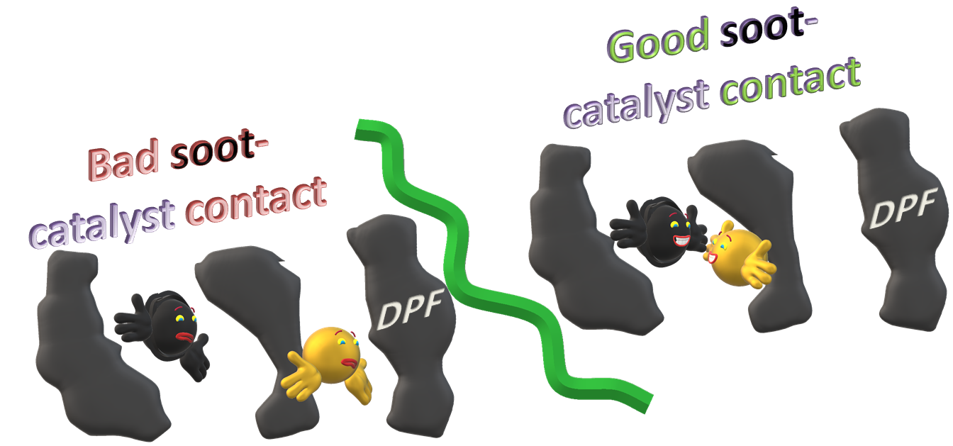
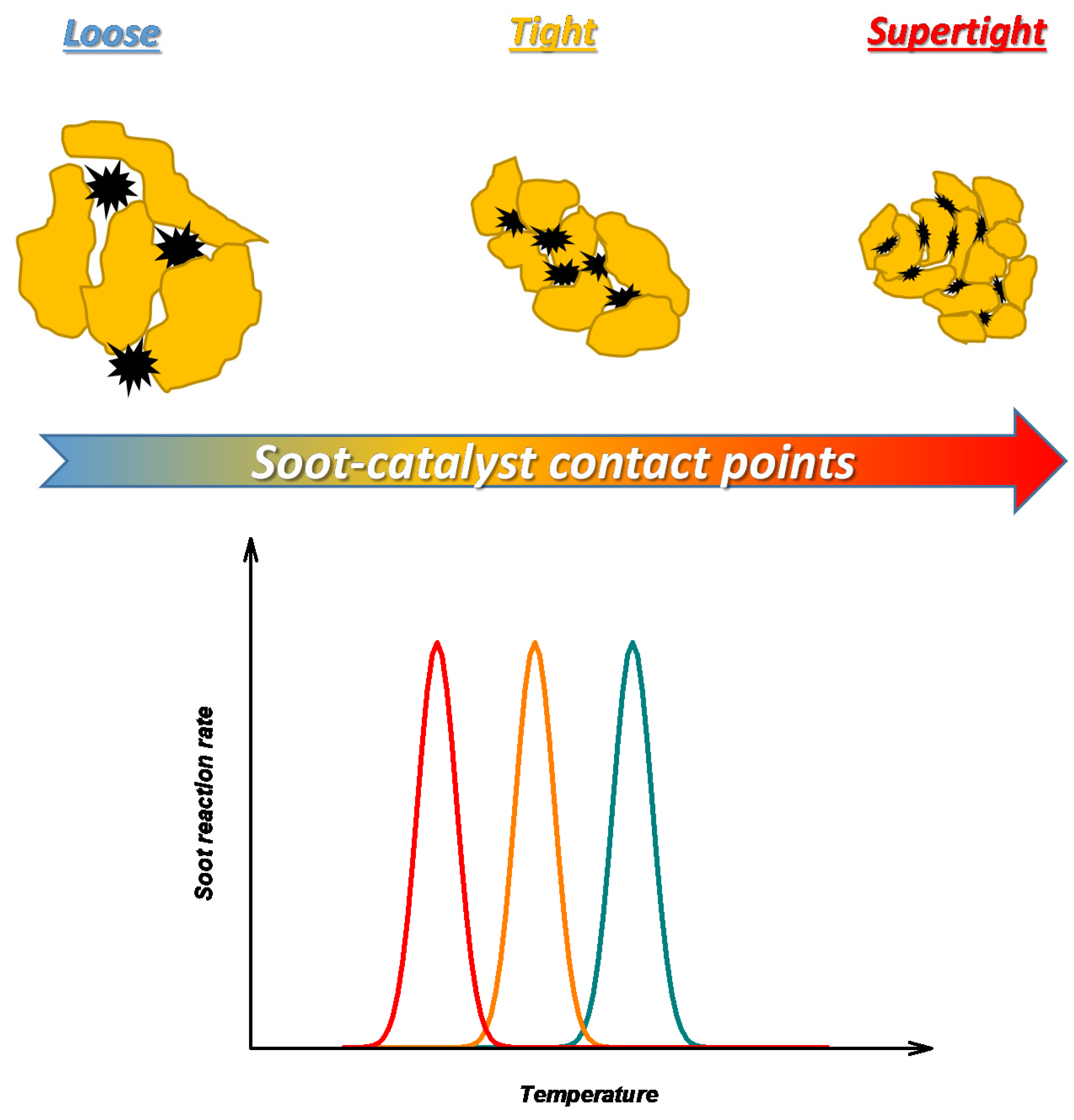
Catalytic regeneration of DPFs has been proposed to overcome or mitigate the issues of thermal regeneration. In the presence of a catalyst, at least in principle, it is possible to lower the temperature required for soot oxidation to well below 600 °C. However, catalytic soot oxidation is a challenging task as it involves a solid-solid catalysis and, thus, its success is dependent not only on catalyst intrinsic activity, but also on the quality of soot-catalyst contact.
The importance of solid-solid contact to an effective soot oxidation has been widely demonstrated by experiments on powdered soot-catalyst mixtures. Different contact modes have been proposed at the lab-scale such as loose, tight, and supertight, listed in ascending order of soot-catalyst contact intensity, i.e., the number of soot-catalyst contact points [
3,
4]. As qualitatively shown in
Figure 1, it has been found that the soot oxidation temperature decreases with an increasing number of soot-catalyst contact points.
Although the results obtained on powders surely provide significant indications, especially in terms of intrinsic activity of materials, they cannot be directly extended to DPFs due to different soot-catalyst contact conditions generated during filtration and subsequent regeneration.
Fuel-borne catalysts (FBCs), i.e., additives that are mixed with the fuel to lead to the formation of catalyst-doped soot during combustion in the engine, have been proposed as catalytic regeneration systems [
5]. Additives are soluble compounds (octanoates, naphthanates, etc.) of metals (copper, iron, cerium, lead, manganese, etc.). Their sacrificial burning produces catalyst particles embedded into soot particles, thus providing intimate soot-catalyst contact. However, such a solution, commercially applied since the early 2000s, has several drawbacks: the need for a second tank for continuous additive supply in the fuel; the accumulation of metal oxide ash inside the DPF; and the fate of catalyst particles after regeneration. To avoid these problems, the catalyst can be directly deposited into (or onto) the walls of catalytic (i.e., catalyst-coated) DPFs.
There are at least three key requirements for the development of well-performing catalytic DPFs: (i) soot oxidation catalysts active at low temperatures; (ii) a good catalyst dispersion; (iii) a suitable soot load. While most of the literature reviews have been focused on point (i) and, more specifically, on catalysts active towards soot oxidation mainly tested as powders (see, e.g., [
6,
7,
8,
9,
10]), in this work, attention is devoted to catalytic DPFs and, in particular, studies dealing with both catalyst dispersion and soot distribution inside the filter are critically reviewed from the perspective of soot-catalyst contact optimization.
In
Section 2, the aspect of catalyst dispersion is discussed. Different techniques can be used to deposit the active layer. Both the preparation technique and catalyst load affect the dispersion of active phase inside the porosity and on the surface of the filter walls, which, in turn, affects not only the interaction with trapped soot particles and the filtration efficiency, but also the pressure drop across the filter. The quality of solid-solid contact and, thus, the regeneration performance are also dependent on soot distribution, which basically depends on soot load. This latter aspect is the subject of
Section 3.
Section 4 outlines the passage to a functioning mode for catalytic DPFs different from the current one to fully exploit their potential in soot abatement. In
Section 5, the main conclusions and perspectives are discussed.
2. Catalyst Dispersion
As previously described, during filtration, soot particles emitted from diesel engines are trapped inside the walls of the DPF channels. More precisely, soot particles are first collected in the filter porous media—the phase of deep-bed filtration—with a consequent progressive modification of filter porosity and permeability, and then a soot cake layer is built up on the porous surface of the filter channels—the phase of cake filtration. During filtration, the pressure drop across the filter increases up to a value requiring regeneration. The phase of deep-bed filtration is characterized by a steep increase in pressure drop with soot load, whereas the phase of cake filtration is characterized by a modest increase in pressure drop with soot load (compared to deep-bed filtration) and almost 100% filtration efficiency [
1]. Soot particles trapped in the form of cake do not retain their original size and morphology, since pressure exerts a force that compacts the soot layer, giving rise to bigger agglomerates [
8].
The catalyst deposition is a critical step from both the filtration and regeneration perspectives. The filtration properties of the bare (uncoated) filter must be retained as much as possible upon catalyst deposition. A uniform distribution of catalyst coating, which prevents the blockage of pores and channels, is required to ensure that the porous structure of the bare DPF is preserved.
As shown by Tsuneyoshi et al. [
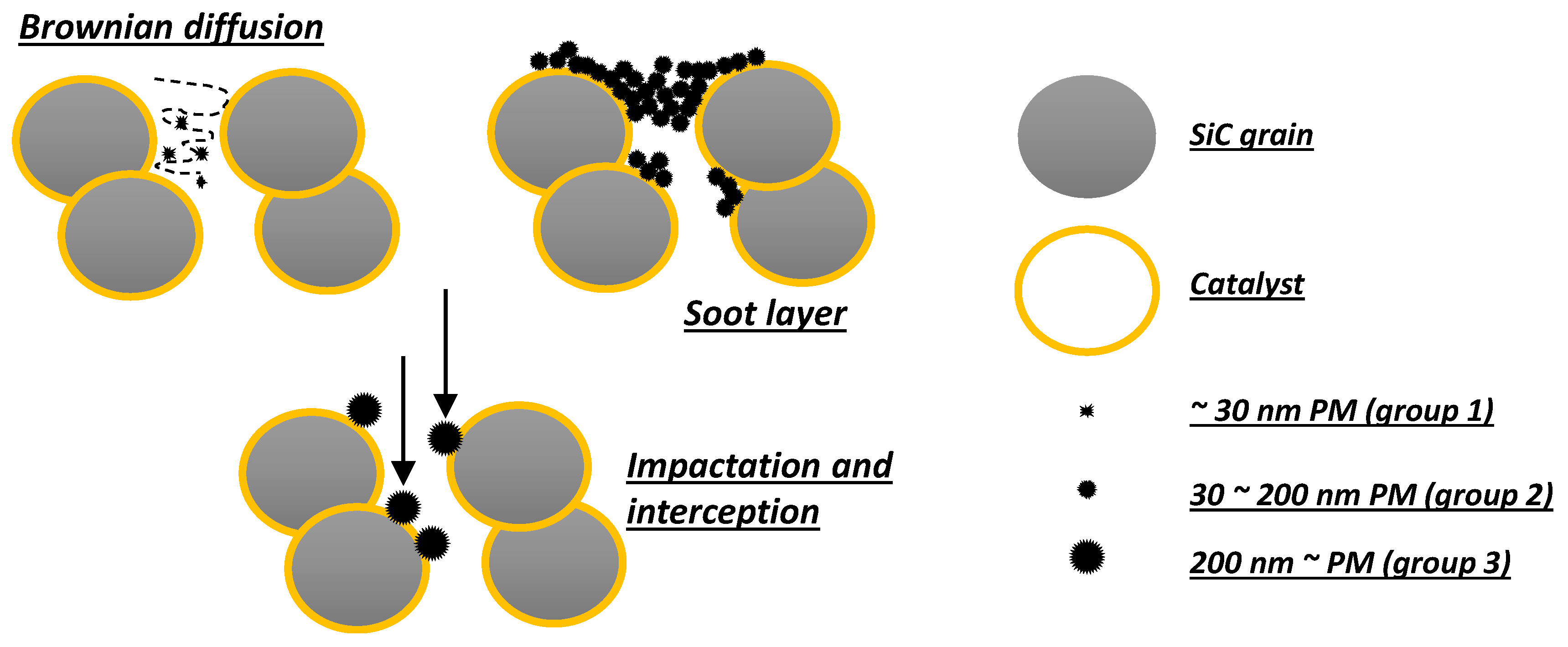
11], the presence of a catalyst coating can greatly affect the filtration properties of a DPF, resulting in a lower porosity and a smaller pore size that, on the one hand, improve the filtration efficiency, but, on the other hand, increase the pressure drop with a strong decrease in gas permeability through the walls. These authors also classified the filtration mechanisms of soot by a catalyst-coated DPF on the basis of soot (PM) particle size [
11]. More precisely, they considered three size groups in the range of (group 1) under 30 nm, (group 2) 30–200 nm, and (group 3) over 200 nm (
Figure 2).
Filtration is the same as the uncoated DPF only for smallest particles that are trapped by Brownian diffusion. On the contrary, filtration of both medium and the biggest particles is affected by the presence of a catalyst coating. Indeed, a soot layer is more easily formed for medium particles, whereas the biggest particles are trapped more efficiently at the start of filtration.
In addition to concerns more properly related to mechanical filtration, which also point out the need for identifying the optimal combination between the catalytic coating and substrate structural properties [
12], it is easy to imagine that the distance between soot and catalyst particles plays a crucial role in soot oxidation, and that the issue of solid-solid contact, widely investigated for powdered soot-catalyst mixtures, is especially critical for catalytic DPFs. Indeed, Hinot et al. [
13], using platinum nano-particles, showed that the catalyst effectiveness in lowering the soot oxidation temperature dramatically dropped in moving from catalyst-doped soot to a thin deposit (5–10 μm) of soot on a catalytic layer due to reduced average distance between soot and catalyst particles.
As highlighted in Fino et al. [
8], the influence of soot-catalyst proximity in a catalytic DPF can be described by a two-layer model [
14], as also deeply discussed by Di Sarli et al. [
15], which is schematically represented in
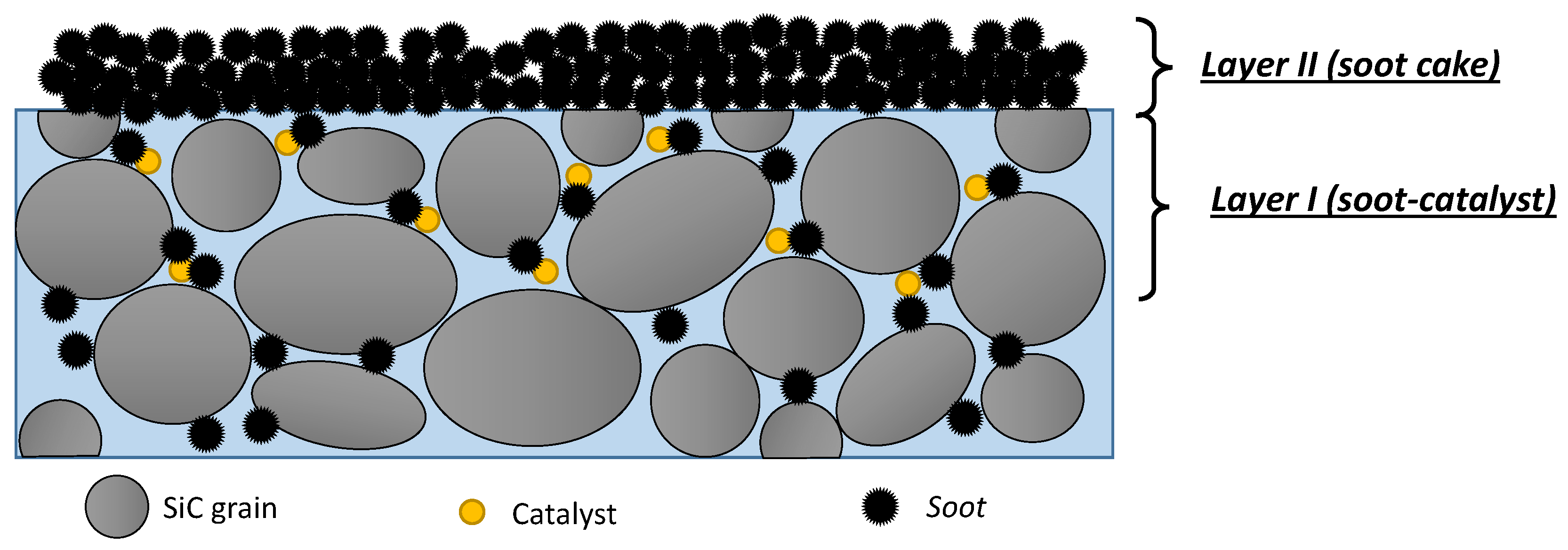
Figure 3.
Layer I is a region influenced by the catalyst coating of the DPF walls and can host a limited amount of soot depending on both filtration velocity and coating structure. Conversely, Layer II, i.e., the soot cake layer, is not in the sphere of influence of the catalyst. Soot particles effectively oxidize when they are within Layer I and come into contact with the catalyst surface. If the catalyst does not penetrate deeply into the filter wall, the inner part of the wall will behave as an uncoated (non-catalytic) wall. This highlights the need for:
- (1)
obtaining a high dispersion with a deep penetration of catalyst into the filter walls, thus increasing both catalyst surface and thickness of Layer I;
- (2)
preventing catalyst deposition from (even if only partially) clogging the wall porosity, thus obtaining a high accessibility of soot particles to the macro-pores of Layer I.
A catalyst deposition achieving both goals (1) and (2) is of paramount importance to the development of catalytic DPFs that perform well during both filtration and regeneration.
For an assigned catalyst load, the ability to distribute the active phase homogeneously and deeply into the filter walls, avoiding its accumulation on the channel surface, strongly depends on the technique used for its deposition [
16]. Indeed, different techniques have been adopted to deposit the active phase onto the DPF monolith, many of which are basically the same as those used for more conventional monoliths, notwithstanding the unusual wall-flow configuration of DPFs [
17]. The main ones are solution combustion synthesis, impregnation, and wash-coating.
Solution combustion synthesis consists in dipping the ceramic support in an aqueous solution of catalyst precursors. After dipping, the filter is placed into an oven at a high temperature to allow the precursor mixture to ignite, thus producing the final active phase. This method has mostly been used for dispersion of perovskites and spinels.
Impregnation consists of the direct deposition of precursors on the monolith by immersion in their solution followed by drying and calcination. It has been used for pure or promoted CeO2 starting from cerium nitrate transformed into the corresponding oxide after calcination.
Wash-coating consists of immersing the monolith into a suspension of catalyst or support particles previously synthesized as powders. It is generally used for metals supported on alumina or zirconia. If the wash-coat does not contain the active metal, this step is followed by its deposition. More specifically, there are three possible methods to deposit the active metal: the metal can be impregnated after the wash-coat deposition and calcination; the active metal precursor can be added to the slurry containing the carrier; the active metal can be deposited onto the carrier powder, calcined and then applied to the filter preparing a slurry of catalyst particles (active metal/carrier).
Only the wash-coating technique involves the preliminary deposition of a carrier. Platinum-group metals can be directly deposited onto cordierite without a previous deposition of a wash-coat layer of a transition-metal oxide carrier with high surface area, as for catalytic DPFs manufactured in the 1990s. Nevertheless, various catalyst carriers, such as alumina, silica and zirconia, have more recently been proposed [
18].
Tang et al. [
19] prepared monolithic catalysts by a two-step procedure. Cordierite monoliths were first wash-coated with porous hollow γ-Al
2O
3 nano-particles by dip-coating. Then, nano-metric LaKCoO
3 or LaCoO
3 perovskite-type oxides were loaded by impregnation from an aqueous solution of metal-precursor salts. The improved soot-catalyst contact conditions, with respect to the one-step deposition of the active phase, were assigned to the introduction of the γ-Al
2O
3 wash-coat providing a great surface area and a high dispersion of active components.
Banùs et al. [
20] reported a first-step application of a thin ZrO
2 layer from a colloidal suspension followed by incorporation of Co, Ba and K, mostly preserving the original cordierite macro-porosity. The catalytic layer also penetrated into the internal pores of the channel walls where a fraction of soot particles was trapped.
On the other hand, many examples can be reported where no carrier was previously deposited. Fino’s group prepared catalytic filters coated with nano-structured and foamy perovskite catalysts, also promoted with gold, by means of solution combustion synthesis [
21,
22,
23,
24]. In agreement with the previous considerations, these authors highlighted the key role played by the final coating structure in determining both a good soot-catalyst contact and a low pressure drop throughout the channel walls.
In Nascimento et al. [
25], Ce-Fe binary mixed oxide catalysts (CeO
x/FeO
y) were directly deposited on cordierite monoliths by the sol-gel technique, and the effect of successive doping with highly dispersed Ag nano-particles was also investigated. The better performance observed for the silver-doped catalytic coating was attributed to an effective soot-catalyst contact improving migration of active oxygen species from catalyst to soot. The same authors also synthesized a Ce-Zn-La mixed oxide (CeO
2-ZnO-La
2O
3) using a lactic acid-mediated sol-gel method, which efficiently coated cordierite substrates for soot capture and combustion [
26].
Maunula et al. [
27] used a proprietary sol-gel method, based on sols with small particles (<100 nm by diameter), to obtain a uniform and well-dispersed coating (containing precious metal—Pt, Pd—as active component) of SiC filter walls that resulted in a lower pressure drop than a non-uniform coating obtained with typical wash-coat slurry. The original pore-size distribution was kept almost unchanged in the pore-size range related to filtration properties, but the coating (20–40 g/L) created micro- and meso-porous surface in a thin (<1 µm) layer. They suggested to wash-coat large-pore SiC substrates due to the higher number of adjusting filtration possibilities with respect to filters having originally narrow pores.
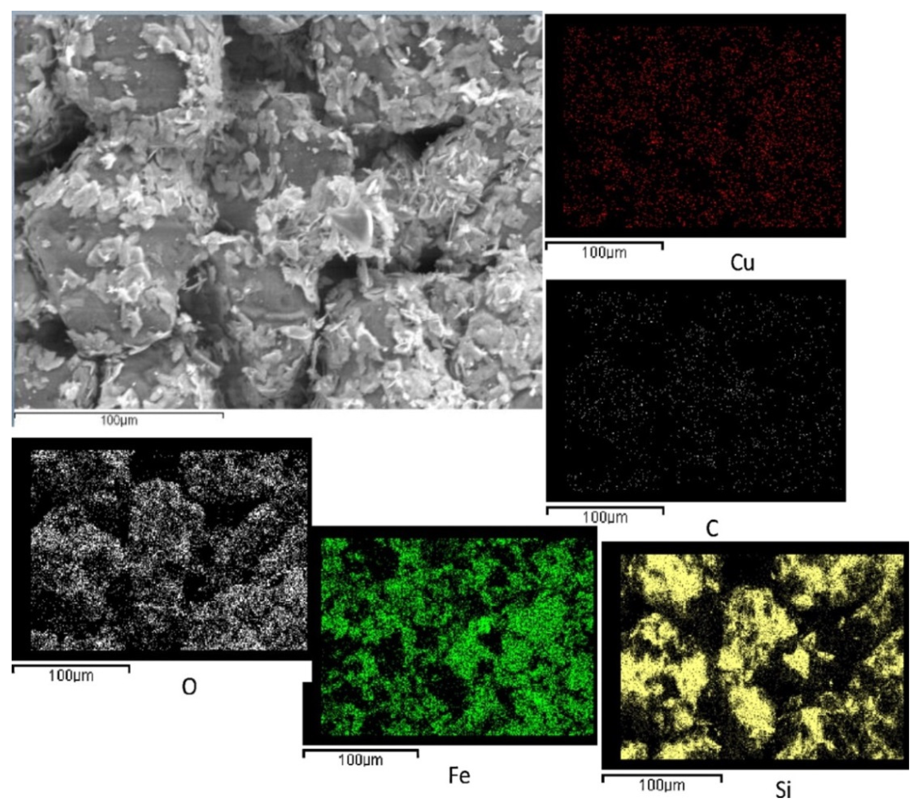
Palma’s group [
28] identified drying and calcination conditions to homogeneously disperse even high loads of CuFe
2O
4 active phase (up to 30% wt) onto a commercial SiC wall-flow filter by repeated impregnations. Low-temperature drying and calcination at 1000 °C, after each impregnation, allowed for a very uniform distribution of both copper and iron, which resulted in a significant increase in soot oxidation rate in the microwave-assisted regeneration process. The good dispersion of copper and iron can be visualized in
Figure 4, showing the SEM image and the EDX maps of the external surface of a channel of a 15% wt CuFe
2O
4 catalyzed filter.
The same group also developed an optimized procedure of catalyst deposition based on a preliminary controlled chemical erosion of the SiC porous structure with an acid solution [
29]. Through this procedure, the initial average pore diameter was increased with respect to the original DPF and, consequently, a higher catalyst load was deposited without affecting the pressure drop.
The dispersion of catalyst as nano-particles seems to be fundamental in determining a good quality of soot-catalyst contact. In agreement with this, Zhou et al. [
30] developed a low-cost electro-less coating approach that allowed in situ growth of well-dispersed nano-structured metal (Pt) crystals inside the DPF pores, thus resulting in a substrate highly active towards soot oxidation. The proposed method also allowed tuning of catalyst morphology by varying the starting reactant concentration and the length of deposition time.
Quiles-Díaz et al. [
31] deposited a nano-sized 2% CuO/ceria-zirconia catalyst on SiC DPFs using a simple and organic solvent-free procedure. The filter was simply dipped into an aqueous solution of the catalyst. The adopted procedure led to a non-continuous deposit of catalyst on the channel walls, thus preventing the blocking of the filter pores.
Other research groups also chose to deposit the catalyst on the DPF in the form of nano-particles, such as in the case of ceria [
15,
32], Pt or ceria-praseodymia (the latter prepared by reversed micro-emulsion) [
16], and Mn
3O
4 (originated from flame-spray pyrolysis) [
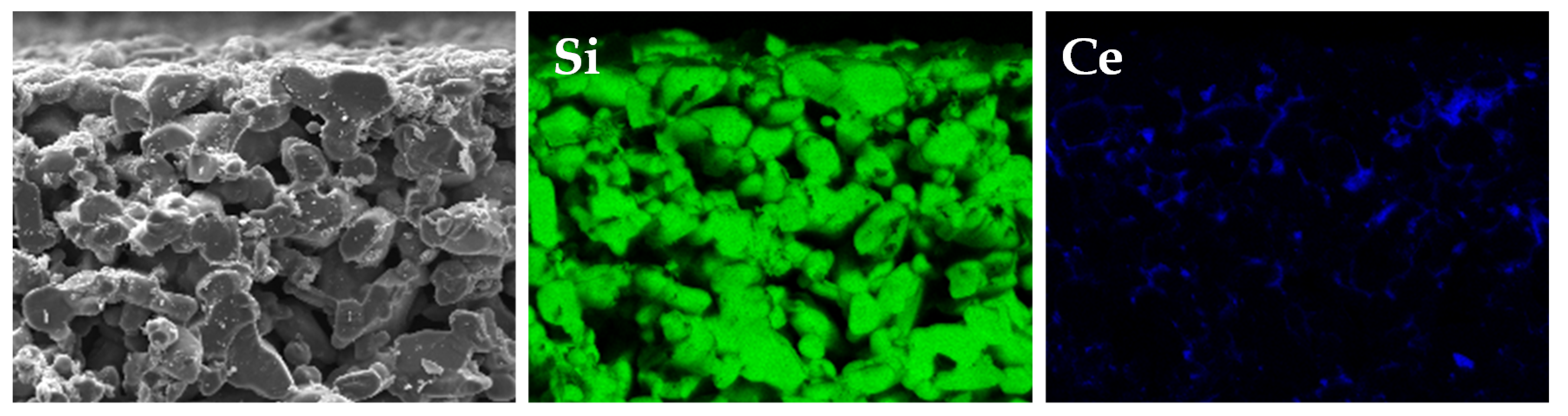
33]. In Di Sarli et al. [
15], a dip-coating procedure was applied to SiC filters starting from a colloidal suspension consisting of ceria nano-particles in a solution of acetic acid. As shown in the SEM image and the EDX maps of the cross section of a filter channel of
Figure 5, a high dispersion with a deep penetration of ceria into the macro-pores of the filter walls was obtained. Indeed, in order to preserve the filtration properties of the SiC substrate and, at the same time, promote the contact between soot and catalyst particles inside the wall porosity, the accumulation of a wash-coat layer on top of the channel walls was prevented (also thanks to a suitably low catalyst load), thus ensuring the accessibility of soot to the macro-pores of the filter. In other words, both goals (1) and (2) previously described were achieved.
In a more recent work [
34], the same authors also showed that both two-step and simultaneous deposition of metal (Ag or Cu) precursor and nano-sized CeO
2 on SiC DPFs resulted in a homogeneous metal dispersion on the ceria coating layer.
Finally, it is worth mentioning the works by Tuler et al. [
35,
36] and Yang et al. [
37], where non-traditional substrates were used. Tuler et al. prepared wall-flow filters starting from sepiolite [
35], a type of low-cost natural clay, or sepiolite/SiC mixtures [
36]. The porosity of the filters was tuned by the addition of pore-generating agents, i.e., organic materials whose combustion led to the formation of interconnected macro-pores. Active elements (Co, Ba, and K [
35,
36], or Co and Ce [
36]) were dispersed either by incorporating them into the dough [
35] or by successive impregnation [
35,
36]. This latter technique assured a good distribution of active elements on both external and internal pore surface and, at the same time, it avoided the exposure of the catalyst to the high calcination temperature needed to remove additives but causing potassium loss [
35].
Yang et al. [
37] loaded, by means of iso-volumetric impregnation, a Co
3O
4-CeO
2 (CoCe) catalyst on a non-traditional substrate, the so-called SBA-15 monolith (SM), having a cross-linked macro-porous structure with a high specific surface area. They found an optimal CoCe/SM ratio maximizing the contact between soot and catalyst and, thus, the catalytic activity. At very low CoCe/SM ratios, active components were mainly located in the meso-porous channels and their contact with soot was very poor. As the CoCe/SM ratio was increased, the catalytic activity first increased and then decreased due to the agglomeration of excess Co
3O
4-CeO
2 composite material.
The scarce effectiveness of the active phase located within meso-pores was also demonstrated by Álvarez-Docio et al. [
38], although for powdered systems. These authors proposed a catalyst prepared by means of the mechanical dispersion of Pt nano-particles on α-Al
2O
3 micro-particles that performed even better than a catalyst with the same composition but prepared by means of wet impregnation of γ-Al
2O
3, a support with a surface area one order of magnitude higher. They highlighted the critical role of soot-catalyst contact showing that the location of platinum on the external surface of the support, avoiding its confinement within meso-pores, promoted contact with soot particles despite the low surface area of α-Al
2O
3.
3. Soot Distribution
As previously discussed, the importance of soot-catalyst contact to an effective soot oxidation has been widely demonstrated by experiments on powdered soot-catalyst mixtures. However, the soot-catalyst contact conditions generated during filtration and subsequent regeneration are completely different from those of soot-catalyst mixtures. This means that to examine what happens on catalytic DPFs under as realistic as possible conditions is a crucial step [
39].
The regeneration performance of catalytic DPFs is strongly dependent not only on the quality of catalyst dispersion, but also on soot load (i.e., for a fixed amount of catalyst loaded on the filter, on catalyst/soot ratio), which directly determines its distribution inside the filter.
Rico Pérez and Bueno-López [
16] loaded nano-particles of Pt or an optimized ceria-praseodymia active phase on SiC DPFs, and designed an experimental set-up where a suspension of soot particles in air was forced to pass through the filter, thus mimicking filtration in a real device. The results of regeneration tests carried out at different soot loads (and constant catalyst load) show that, with both catalyst types, catalytic regeneration was hindered below a critical catalyst/soot ratio. This finding is attributed to the weakening of the soot-catalyst contact with increasing soot load. It was argued that the first soot particles loaded have more chances to come into contact with catalyst particles than particles loaded afterwards. However, the link between the critical catalyst/soot ratio and the localization of contacted and non-contacted soot entities inside the filter was not elucidated.
Quiles-Díaz et al. [
31] investigated the effect of different soot loads (at an assigned catalyst load) on the regeneration performance of SiC DPFs onto which a nano-sized 2% CuO/ceria-zirconia catalyst was incorporated. Similarly to Rico Pérez and Bueno-López [
16], these authors highlighted the importance to avoid catalyst/soot ratios lower than a critical ratio as they led to lower catalytic activities.
The two-layer model schematized in
Figure 3 has been used to account for the two-stage evolution of soot combustion during temperature-programmed oxidation tests [
8]. For an assigned catalyst/soot ratio, Wagloehner et al. [
33] quantified, from the two-stage evolution of CO
x (= CO + CO
2) concentration recorded during temperature-programmed regeneration of a DPF coated with a nano-sized Mn
3O
4 catalyst, the percentage of total soot trapped inside the filter in weak/intimate contact with the catalyst. They found that most of the soot (around 80%) was in weak contact with the catalyst, causing oxidation above 400 °C, whereas a minor fraction of soot (around 20%) was in intimate contact with the catalyst, evoking conversion already between 180 and 350 °C. Kumar et al. [
32] found similar findings from temperature-programmed regeneration of a DPF coated with a layer of CeO
2 nano-fibers. The deconvolution of the CO
2 concentration curve into two contributions allowed them to estimate that around 70% of the overall amount of combusted soot was oxidized catalytically, while the remaining part was oxidized via the non-catalytic path. The catalytic peak was centered at a temperature around 120 °C lower than the non-catalytic peak.
Di Sarli et al. [
15] investigated the effect of the catalyst/soot ratio on the regeneration performance of SiC DPFs wash-coated with a highly dispersed ceria (
Figure 5). They found a transition from a regime of almost purely catalytic regeneration to a regime of catalyst-assisted thermal regeneration with decreasing catalyst/soot ratio (i.e., increasing soot load). In the former regime, most of the soot was trapped inside the wall porosity, thus coming into intimate contact with the catalyst. Under such conditions, regeneration occurred via the catalytic path at low temperatures. In the latter regime, most of the soot was accumulated in the form of a rather thick cake layer (15–20 μm) on top of the channel walls. The soot cake was burned off via the thermal path at high temperatures, being far from the catalyst.
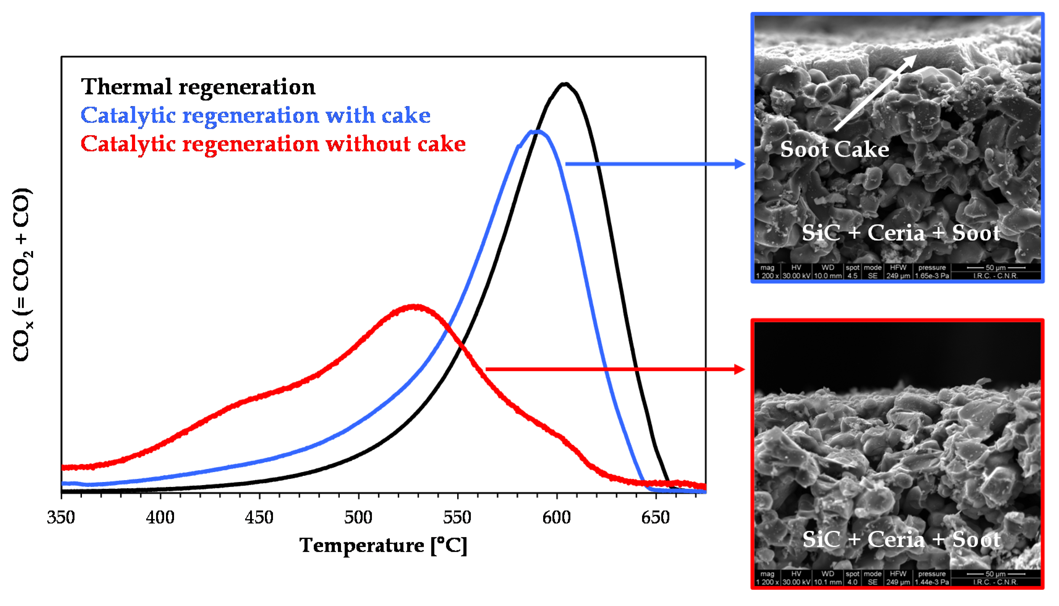
Figure 6 is the graphical abstract of this work. It shows the plots of CO
x concentration versus filter temperature as recorded during three heating-ramp regeneration tests: thermal regeneration; catalytic regeneration with cake (high soot load and, thus, low catalyst/soot ratio); catalytic regeneration without cake (low soot load and, thus, high catalyst/soot ratio). The images on the right-hand side are SEM images showing the cross section of a channel of the ceria-coated DPF with cake (top image) and without cake (bottom image).
This figure confirms that, as discussed in
Section 2, the cake layer (Layer II in
Figure 3) is not in the sphere of influence of the catalyst. Conversely, from the deconvolution of the red curve (catalytic regeneration without cake), it was estimated that around 80% of the overall amount of combusted soot was oxidized via the catalytic path [
15]. Thus, once a high dispersion with a deep penetration of catalyst into the macro-pores of the filter walls is assured (
Figure 5), in order to optimize the contact between soot and catalyst, thus making regeneration of the DPF a truly catalytic process, it is essential to minimize the thickness of the cake layer, approaching its disappearance. This conclusion is supported further by the results of CFD-based simulations of soot combustion dynamics in a catalytic DPF showing that, once it is assumed that all the soot trapped inside the filter walls is in contact with the catalyst, fast and at the same time safe (i.e., low-temperature) regeneration is not feasible [
40,
41,
42] unless the accumulation of soot in the form of cake on top of the catalytic walls is prevented [
42,
43,
44]. Indeed, catalytic oxidation of the soot trapped inside the walls is only a pilot causing violent ignition of the soot cake, whose fast combustion process leads to high peak temperatures [
40,
41,
42].
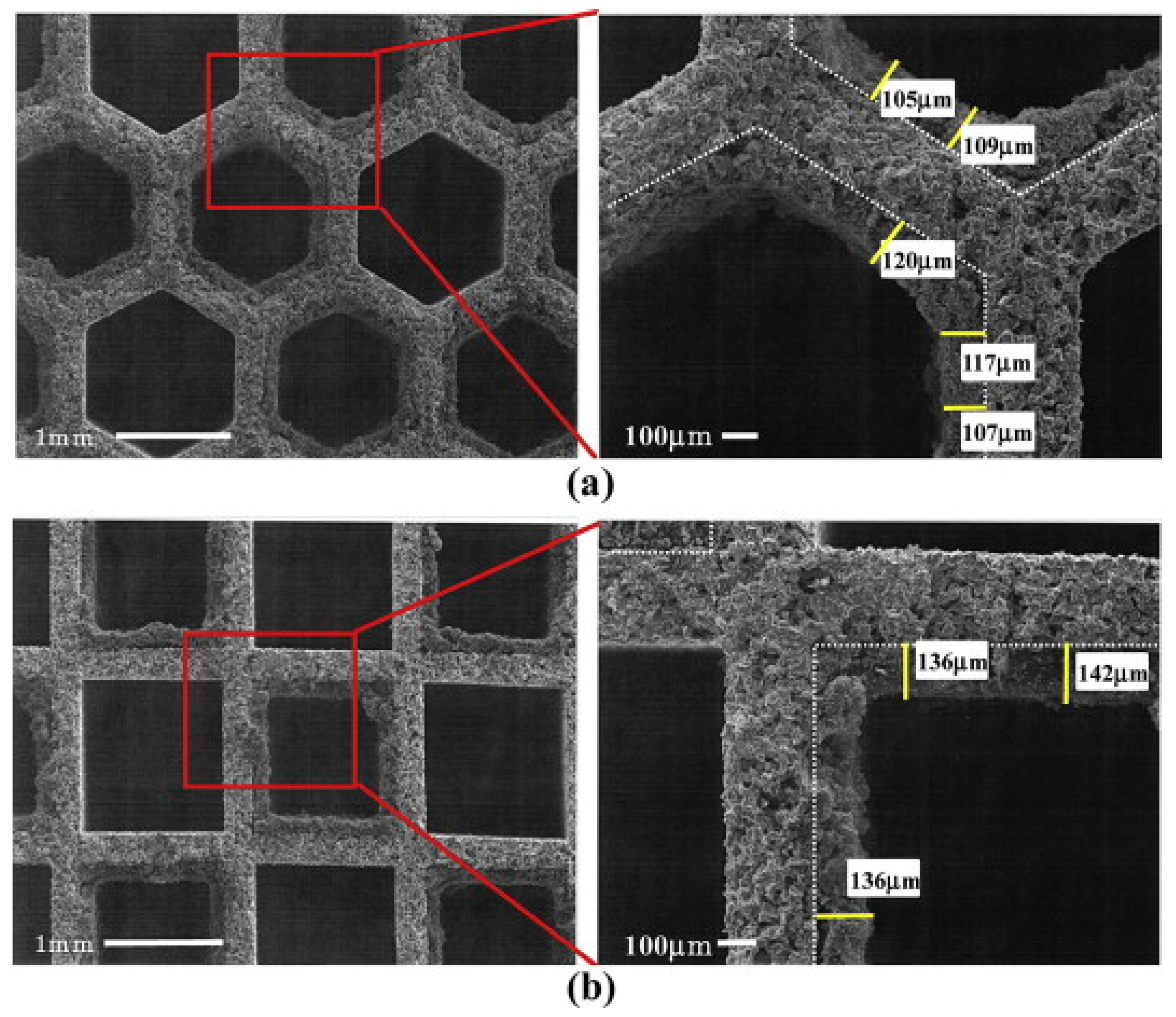
The importance of the cake thickness was also highlighted by Tsuneyoshi and Yamamoto [
45], who compared hexagonal- and square-cell DPFs. In the former case, the soot cake was wider and thinner with lower back pressure, because the hexagonal-cell DPF has a larger aperture ratio and a larger filtration area (
Figure 7).
In addition, under controlled regeneration conditions (i.e., constant oxygen concentration and temperature of the inlet gas), enhanced soot oxidation and higher regeneration efficiency were found for the catalytic DPF with hexagonal cells.
4. Towards Continuous Operation
As highlighted in
Section 1, at the end of filtration, soot is trapped mostly in the form of cake. Soot accumulation inside the DPF increases the back pressure of the diesel engine, reducing its efficiency. A low and constant back pressure can be maintained if the filtration properties are preserved during normal operation, and this can occur if a constant accessibility to filter porosity is assured, while preventing excessive accumulation of soot as cake.
On the other hand, from the perspective of soot-catalyst contact optimization, the results shown in
Figure 6 point out the need for minimizing/avoiding the formation of cake. In addition, as already mentioned in
Section 3, avoiding the accumulation of cake is of paramount importance in preventing high temperature excursions that arise under conditions of fast regeneration, possibly causing damage to the catalytic DPF. However, in the absence of cake, fast low-temperature regeneration can be carried out provided that operating conditions are properly chosen [
42,
43,
44]. In this respect,
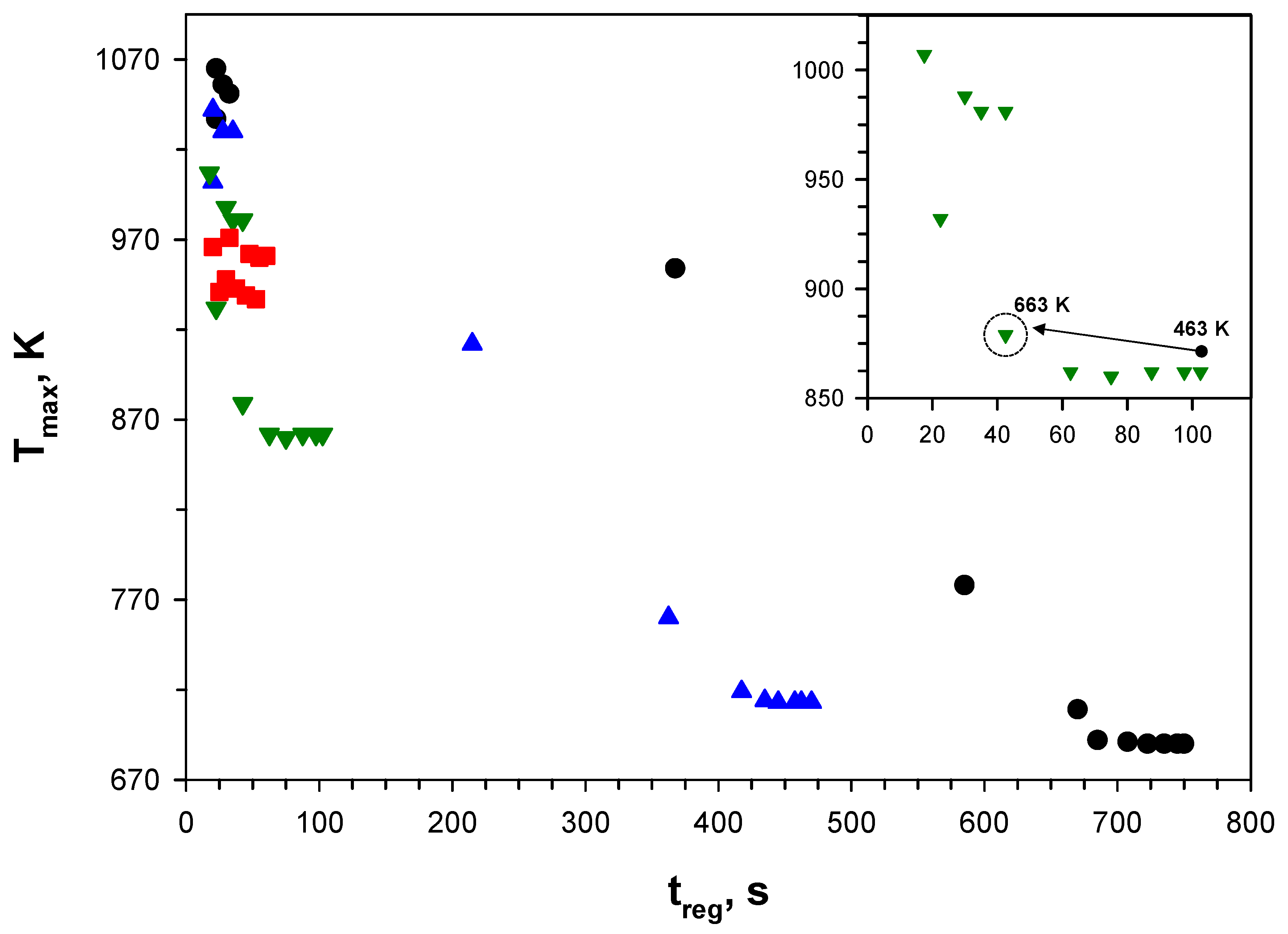
Figure 8 shows the operating map of a catalytic DPF in the plane maximum filter temperature, T
max, versus time for filter regeneration, t
reg, as recently reported in Landi et al. [
44]. The map was built from the results of CFD-based simulations of soot combustion in a single-channel configuration run by varying the initial temperature of the filter at different catalyst activities. In those simulations, the inlet gas temperature was kept constant (and equal to 663 K).
According to this figure, at intermediate catalyst activity, fast regeneration can be carried out at sufficiently low temperatures, so as to preserve the thermal stability of the catalyst [
7], over a rather broad range of initial temperatures (463–663 K—see the inset). The best compromise between time for regeneration and maximum temperature is achieved with the initial temperature of the filter set equal to the inlet gas temperature (i.e., at 663 K).
The above considerations pave the way for the passage to a continuous functioning mode for catalytic DPFs, with regeneration taking place simultaneously, and not alternately, to filtration at the conditions of the exhaust gases fed to the filter. In principle, this functioning mode can assure a low and constant soot load, which implies a low and constant pressure drop, avoiding the drawbacks of periodic regeneration.
The soot emitted from the diesel engine is continuously trapped inside the catalytic DPF, and the trapped soot is burned off during continuous regeneration. At the equilibrium, the mass of trapped soot equals the mass of oxidized soot and, thus, a condition of constant soot load is attained. The temperature at which this equilibrium is established is called the balance point temperature, and is defined as that assuring a constant pressure drop across the filter [
46].
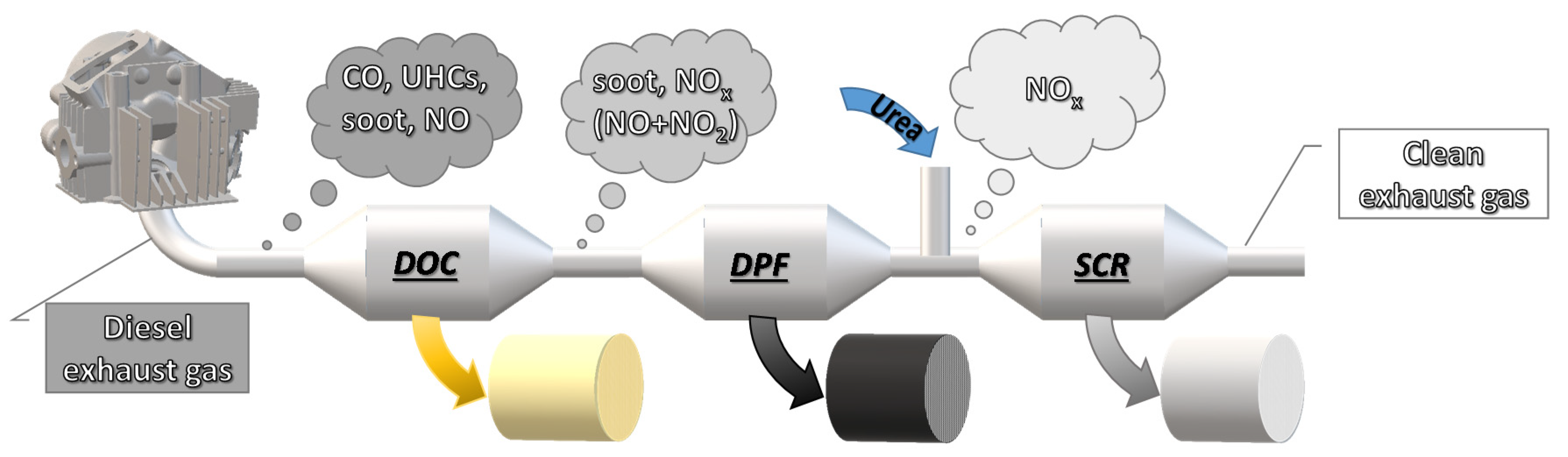
Continuous regeneration of catalytic DPFs has already been proposed according to the scheme of
Figure 9 that couples diesel oxidation catalyst (DOC) and DPF (see, e.g., [
47,
48,
49,
50]). This continuous mode is based on NO
2-assisted regeneration.
NO
2 oxidizes soot more effectively than O
2 at lower temperature (about 300 °C lower). In the DOC unity, which consists of a cordierite monolithic substrate typically coated with a Pt-based catalyst, in addition to oxidation of CO and unburned hydrocarbons (UHCs), NO conversion to NO
2 takes place, thus increasing the quite low NO
2 concentration in the exhaust gas (about 5% to 10% of total NO
x). This increase in NO
2 concentration speeds up the regeneration process [
48] and, thus, largely affects the decrease in back pressure, enhancing the operating performance and prolonging the life-time of the device [
49].
Tang et al. [
47] investigated continuous regeneration of a catalytic DPF (i.e., a wall-flow cordierite substrate coated with a Pt-Pd catalyst) placed downstream of a DOC on an engine test bench, and determined the balance point temperature by measuring the trend of solid particle number (SPN) concentration downstream of the catalytic DPF, with and without DOC. They found that the balance point temperature decreased from 356 to 303 °C by introducing the upstream DOC unity.
Palma’s group reported a balance point temperature of 320 °C (at constant pressure drop) for a SiC DPF wash-coated with a CuFe
2O
4 catalyst and placed downstream of a DOC [
50]. The catalytic DPF, prepared following the procedure based on chemical erosion of the SiC porous structure mentioned in
Section 2 [
29], also allowed for a high filtration efficiency (96%).
In the configuration of
Figure 9, nitrogen oxides exiting the DPF are generally reduced in a final selective catalytic reduction (SCR) unity. However, in the last few years, after-treatment systems integrating DPF and NO
x SCR into a single SCR-on-Filter (SCRoF) device have largely been spreading. In the SCRoF, soot oxidation is inhibited as NO
2 is consumed in the kinetically much faster SCR reaction, leaving no NO
2 for soot oxidation [
51]. As a consequence, the feasibility of a continuous process exploiting the large O
2 excess in diesel engine exhausts, simultaneously or not to SCR, must be addressed. This is a challenging task as it entails, among others, the development of highly active catalytic coatings enabling continuous soot oxidation over the temperature range of diesel exhausts (200–350 °C) even without NO
2 assistance. However, some encouraging results in this direction have already been obtained [
15,
32,
33,
34,
52].
In Di Sarli et al. [
52], the potential of continuous regeneration with only O
2 as the oxidant was explored through isothermal tests aimed at defining the minimum temperature leading to filter regeneration through oxidation of the soot trapped inside the wall porosity in intimate contact with a highly dispersed catalyst. In those tests, through a proper choice of soot load, the formation of the cake layer was prevented. Using a simple CeO
2 catalyst, the authors found that 475 °C assured filter regeneration, while preserving the catalyst stability over repeated cycles of soot loading and oxidation. In a more recent work [
34], the same authors also showed that the regeneration performance of the catalytic DPF can be improved by promoting ceria with a proper active metal (Ag or Cu), thus significantly decreasing the temperature required for soot oxidation.
5. Conclusions and Outlook
The most important developments in the field of the regeneration of catalytic DPFs have been reviewed, focusing on the dispersion of the catalyst inside the walls of the filter channels rather than on its intrinsic activity towards soot oxidation. The latter issue has been widely investigated under conditions of intimate soot-catalyst contact. However, these conditions are quite far from those of real catalytic DPFs, whose problems mainly stem from a rather weak solid-solid contact established during filtration and subsequent regeneration.
Among the different techniques used for catalyst deposition on the DPF, particular emphasis has been given to those leading to a high dispersion with a deep penetration of catalyst into the macro-pores of the filter walls, while preserving the filtration properties of the bare support so as to allow for a high accessibility of soot particles to the wall porosity. Sol-gel methods and dip-coating using colloidal suspensions of catalyst nano-particles are two examples of the best-performing techniques.
The quality of soot-catalyst contact and, thus, the regeneration performance of catalytic DPFs also depend on soot distribution, which in turn depends on soot load. The most important works aiming at quantifying the link between regeneration performance and soot load/distribution have also been reviewed. The main conclusion drawn from the literature analysis is that, once a good catalyst dispersion inside the filter macro-pores is assured, in order to optimize soot-catalyst contact, thus making regeneration of the DPF a truly catalytic process, it is essential to minimize the thickness of the soot cake layer accumulated on top of the channel walls, approaching its disappearance. The soot cake is substantially segregated from the catalyst and, as such, burns via the thermal path at high temperatures.
At the end of filtration, soot is trapped mostly in the form of cake. Thus, avoiding the formation of cake paves the way for the passage to a continuous functioning mode for catalytic DPFs, with regeneration taking place simultaneously, and not alternately, to filtration. Continuous regeneration has already been proposed as an NO2-assisted process according to a scheme coupling DOC and DPF. In the DOC unity, NO is converted into NO2, which decreases the temperature required for soot oxidation in the downstream DPF, being a much stronger oxidizing agent than O2. Nevertheless, NO2 concentration is often not sufficient to enable continuous DPF regeneration over the temperature range of exhaust gases and, in any case, it is limited by NO emitted from the engine. On the other hand, the appealing perspective to continuously burn the soot trapped inside the filter exploiting the large O2 excess in diesel exhausts can be realized, once the soot-catalyst contact is optimized, using new more active catalyst formulations. For this purpose, the study of the catalyst intrinsic activity plays again a fundamental role.


